EP2789216B1 - Getriebesteuermodul - Google Patents
Getriebesteuermodul Download PDFInfo
- Publication number
- EP2789216B1 EP2789216B1 EP12784485.0A EP12784485A EP2789216B1 EP 2789216 B1 EP2789216 B1 EP 2789216B1 EP 12784485 A EP12784485 A EP 12784485A EP 2789216 B1 EP2789216 B1 EP 2789216B1
- Authority
- EP
- European Patent Office
- Prior art keywords
- gearbox
- control module
- module
- transmission
- module carrier
- Prior art date
- Legal status (The legal status is an assumption and is not a legal conclusion. Google has not performed a legal analysis and makes no representation as to the accuracy of the status listed.)
- Not-in-force
Links
- 238000001816 cooling Methods 0.000 claims description 4
- 230000005540 biological transmission Effects 0.000 description 101
- 238000005516 engineering process Methods 0.000 description 3
- XAGFODPZIPBFFR-UHFFFAOYSA-N aluminium Chemical compound [Al] XAGFODPZIPBFFR-UHFFFAOYSA-N 0.000 description 1
- 229910052782 aluminium Inorganic materials 0.000 description 1
- 239000003990 capacitor Substances 0.000 description 1
- 239000000969 carrier Substances 0.000 description 1
- 230000001419 dependent effect Effects 0.000 description 1
- 238000009429 electrical wiring Methods 0.000 description 1
- 230000005669 field effect Effects 0.000 description 1
- 239000012530 fluid Substances 0.000 description 1
- 238000004519 manufacturing process Methods 0.000 description 1
- 238000007789 sealing Methods 0.000 description 1
- 238000000926 separation method Methods 0.000 description 1
Images

Classifications
-
- F—MECHANICAL ENGINEERING; LIGHTING; HEATING; WEAPONS; BLASTING
- F16—ENGINEERING ELEMENTS AND UNITS; GENERAL MEASURES FOR PRODUCING AND MAINTAINING EFFECTIVE FUNCTIONING OF MACHINES OR INSTALLATIONS; THERMAL INSULATION IN GENERAL
- F16H—GEARING
- F16H61/00—Control functions within control units of change-speed- or reversing-gearings for conveying rotary motion ; Control of exclusively fluid gearing, friction gearing, gearings with endless flexible members or other particular types of gearing
- F16H61/02—Control functions within control units of change-speed- or reversing-gearings for conveying rotary motion ; Control of exclusively fluid gearing, friction gearing, gearings with endless flexible members or other particular types of gearing characterised by the signals used
- F16H61/0202—Control functions within control units of change-speed- or reversing-gearings for conveying rotary motion ; Control of exclusively fluid gearing, friction gearing, gearings with endless flexible members or other particular types of gearing characterised by the signals used the signals being electric
-
- F—MECHANICAL ENGINEERING; LIGHTING; HEATING; WEAPONS; BLASTING
- F16—ENGINEERING ELEMENTS AND UNITS; GENERAL MEASURES FOR PRODUCING AND MAINTAINING EFFECTIVE FUNCTIONING OF MACHINES OR INSTALLATIONS; THERMAL INSULATION IN GENERAL
- F16H—GEARING
- F16H61/00—Control functions within control units of change-speed- or reversing-gearings for conveying rotary motion ; Control of exclusively fluid gearing, friction gearing, gearings with endless flexible members or other particular types of gearing
- F16H61/0003—Arrangement or mounting of elements of the control apparatus, e.g. valve assemblies or snapfittings of valves; Arrangements of the control unit on or in the transmission gearbox
- F16H61/0006—Electronic control units for transmission control, e.g. connectors, casings or circuit boards
-
- H—ELECTRICITY
- H05—ELECTRIC TECHNIQUES NOT OTHERWISE PROVIDED FOR
- H05K—PRINTED CIRCUITS; CASINGS OR CONSTRUCTIONAL DETAILS OF ELECTRIC APPARATUS; MANUFACTURE OF ASSEMBLAGES OF ELECTRICAL COMPONENTS
- H05K5/00—Casings, cabinets or drawers for electric apparatus
- H05K5/0026—Casings, cabinets or drawers for electric apparatus provided with connectors and printed circuit boards [PCB], e.g. automotive electronic control units
- H05K5/0082—Casings, cabinets or drawers for electric apparatus provided with connectors and printed circuit boards [PCB], e.g. automotive electronic control units specially adapted for transmission control units, e.g. gearbox controllers
-
- Y—GENERAL TAGGING OF NEW TECHNOLOGICAL DEVELOPMENTS; GENERAL TAGGING OF CROSS-SECTIONAL TECHNOLOGIES SPANNING OVER SEVERAL SECTIONS OF THE IPC; TECHNICAL SUBJECTS COVERED BY FORMER USPC CROSS-REFERENCE ART COLLECTIONS [XRACs] AND DIGESTS
- Y10—TECHNICAL SUBJECTS COVERED BY FORMER USPC
- Y10T—TECHNICAL SUBJECTS COVERED BY FORMER US CLASSIFICATION
- Y10T74/00—Machine element or mechanism
- Y10T74/20—Control lever and linkage systems
- Y10T74/20012—Multiple controlled elements
- Y10T74/20018—Transmission control
- Y10T74/2003—Electrical actuator
Definitions
- the invention relates to a transmission with a hydraulic control module and a transmission control module for a vehicle.
- a transmission is from the DE-A-19710931 known.
- Attachment controllers may have the advantage over integrated controllers that they are exposed to lower temperatures, and thus can be designed more cost-effective.
- the disadvantage can arise that add-on appliances in the engine compartment require a lot of space and the effort is higher to lead electrical lines from the outside to the inside of the transmission sensors and actuators.
- Integrated control devices are generally constructed as so-called electronic control modules and may include an electronic circuit or an electronic module ("transmission control unit", TCU), sensors, at least one connector for connection to the vehicle wiring harness and electrical interfaces for driving actuators.
- TCU transmission control unit
- sensors at least one connector for connection to the vehicle wiring harness and electrical interfaces for driving actuators.
- the transmission control module comprises an electronic module with an electronic circuit for controlling the transmission, electrical connections, for example for connecting the electronic module with a wiring harness (for example in the engine compartment) and / or for connecting the electronic module to the transmission (approximately via lines in the Interior of the gearbox) and a module carrier on which the electronic module and the electrical connections are mounted.
- the module carrier is designed as a cover for sealingly closing a transmission interior. In other words, the module carrier can simultaneously assume the function of a cover or an oil pan for the transmission.
- a component cover or oil pan
- the transmission control module can also assume the function of a cover and a part of its components are arranged in the interior of the transmission, the transmission control module can have a small space requirement in the engine compartment. With the transmission control module, the assembly effort and the number of required items can be reduced. In this case, the low wiring complexity of a control unit integrated in the transmission can be maintained: It must be done in the rule sealed only in the engine compartment, the electrical wiring from the electronic module (TCU) to the vehicle wiring harness from the transmission interior. This can be achieved for example via a gearbox plug.
- the module carrier has the function of mechanically holding and supporting all components of the transmission control module.
- the module carrier may be made of plastic or of a metallic carrier (for example aluminum). With the cover of the gearbox through the module carrier, a transmission oil-tight separation from the transmission interior to the engine compartment is created.
- the module carrier can be designed oil-tight and has, for example, no holes or other Aussparrept that are not closed.
- the module carrier comprises a module carrier plate.
- the cover can thus form a substantially flat lid, which is attached via a flange of the gear housing to the transmission.
- the module carrier or the module carrier plate thus has an inner surface facing the gearbox interior and an outer surface facing the engine compartment.
- the transmission control module comprises a transmission connector for connecting a cable harness to the transmission control module.
- the gear plug is integrated, for example, through an opening or recess in the module carrier in the module carrier.
- the integrated gearbox plug also reduces the mechanical effort required to connect to the vehicle wiring harness.
- a required for conventional control units tolerance compensation to mount the plug during assembly of the transmission control module in the transmission housing can be omitted, since the plug can be integrated directly into the module carrier.
- the gear connector normally has the function of establishing an interface from the electronic module (TCU) in the gearbox interior to the vehicle wiring harness in the engine compartment.
- the plug can be mounted as a separate part in the module carrier plate. With a plastic version of the module carrier, the plug can also be injected directly into the module carrier. According to one embodiment of the invention, the gear plug is mounted as a separate part sealingly in a recess in the module carrier. According to one embodiment of the invention, the gearbox plug is injected into the module carrier.
- the electronic component is arranged on an inner side of the module carrier and the electronic component is thermally connected to the module carrier.
- the transmission control module can use the low ambient temperature of the engine compartment to cool the electronics of the electronic module.
- the electronic module (TCU) is thermally connected to the module carrier such that a power loss can be dissipated to the outside in the cooler engine compartment.
- the cooling surface of the transmission control module (for example, the outside of the module carrier) may be outside the transmission.
- the module carrier transfers the heat to the cooler engine compartment environment. This can mean a much lower cost for cooling the electronics.
- the electronic module (TCU) and its electrical connections are arranged in the interior of the transmission. All components with interfaces within the gearbox can be connected with little wiring effort.
- electrical connections, sensors, and an adapter plug can be integrated in the gearbox control module: these elements can be mounted on the inside of the module carrier.
- the electrical connection technology or the Electrical connections can also serve to connect the components of the transmission control module with each other.
- the intermediate plug can be used to connect an electrical line from the interior of the transmission.
- the module carrier is designed as a printed circuit board or as overmolded stamped grid.
- the functions of the electrical connection technology components (i.e., the electrical connections) and module carriers can be integrated into one component.
- This component fulfills the function of covering the gearbox.
- the gear plug is also integrated in this component.
- a motor control module for an electric motor of the transmission is mounted on an outer side of the module carrier. If an electric motor is required for the transmission, it may be useful to mount the electronic components for its control on the outside of the transmission control module. This can have the advantage, in addition to the lower temperatures, that these components do not have to be protected from transmission oil. Since these components are normally connected in series in the electrical line, the number of lines, which are oil-tight out into the transmission interior, must not change.
- the invention relates to a transmission for a vehicle, for example an automatic transmission.
- the transmission comprises a housing with an opening (for example for passing electrical lines into an interior of the transmission) and a transmission control module, as described above and below, which seals the opening.
- the transmission control module can be manufactured by a supplier regardless of the final transmission assembly. The transmission manufacturer can easily install the transmission control module in its transmission. Since the opening is closed by installing the transmission control module, the assembly is simplified.
- the transmission further comprises a hydraulic control module.
- the transmission may include hydraulic components that are controlled by the hydraulic module, which in turn may be controlled by the transmission control module.
- the opening in the transmission housing is bounded by a flange to which the transmission control module is connected.
- the hydraulic control module is mounted between the transmission control module and the opening on the flange.
- the hydraulic control module is covered in a space-saving manner by the transmission control module installed in the transmission.
- the positioning of the transmission control module in the transmission can be simplified because the transmission control module is connected directly to the transmission housing and not indirectly via the hydraulic control module to the transmission housing.
- the Fig. 1 shows a section of a transmission 10, which is enclosed by a transmission housing 12.
- the transmission housing 12 separates an interior 14 of the transmission 12 from an engine compartment 16.
- the transmission housing 12 includes a two-stage flange 18 in the interior of which a hydraulic control module 20 is mounted.
- the hydraulic control module 20 rests on an inner shoulder of the flange 18 and is bolted to the flange 18 there.
- the transmission 10 can be hydraulically operated. Instead of a hydraulic actuation and an electromechanical actuation system for the transmission can be used.
- a transmission control module 22 On an outer shoulder of the flange 18 sits a transmission control module 22 on the flange 18 and is bolted to the flange 18 there.
- the transmission control module 22 comprises a carrier plate 24, in which a gear plug 26 is integrated and on whose inner side 28 an electronic component (TCU) 30 is mounted. arranged inside the gear housing.
- TCU electronic component
- the gear plug 26 is guided through a recess or opening in the support plate 24 and mounted by means of a sealing ring 32 to the support plate 24 such that the opening is sealed oil-tight.
- the transmission control module 22 can be electrically connected to a wiring harness of the vehicle in which the transmission 10 is installed.
- the electronic component 30 and an electrical connection technology 34 with electrical leads 34 are attached to the inside 28 of the transmission control module 22.
- the sensor 36 protrudes through an opening 38 in the transmission housing 12, through which electrical lines can also lead into the interior of the transmission 10 and which is surrounded by the flange 18.
- the transmission control module 22 may further include an adapter plug for connection to an electrical line inside the Gear 10 and an actuator contact for connection to an actuator of the transmission 10 may be attached to the transmission control module 22.
- Components, such as the components 20, 30, 34, 36, in the transmission interior 14 are wholly or partially directly in the transmission fluid (ATF) and the temperatures (-40 ... + 150 ° C), which occur in the transmission 10 exposed be.
- Components outside the transmission 10 in the engine compartment 16 may be exposed to temperatures up to about 120 ° C. Therefore, an outer surface 40 of the support plate 24 serves as a cooling surface for the transmission control module 22. For better heat conduction of the electronic component is thermally conductively connected to the support plate 24 and can be cooled by this.
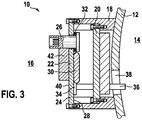
- the Fig. 3 shows a transmission control module 22 on the outside 40 a motor control module 42 is attached, which comprises drive components for an electric motor of the transmission 10.
- An input filter is needed to drive the motor and a B6 bridge is required for an EC motor.
- the input filter consists of capacitors, coils and field effect transistors.
Landscapes
- Engineering & Computer Science (AREA)
- General Engineering & Computer Science (AREA)
- Mechanical Engineering (AREA)
- Microelectronics & Electronic Packaging (AREA)
- General Details Of Gearings (AREA)
- Control Of Transmission Device (AREA)
Description
- Die Erfindung betrifft ein Getriebe mit einem Hydrauliksteuermodul und einem Getriebesteuermodul für ein Fahrzeug. Ein derartiges Getriebe ist aus der
DE-A-19710931 bekannt. - Zur Steuerung von Automatikgetrieben werden elektronische Steuerungen verwendet, die entweder im Inneren des Getriebegehäuses angeordnet sind (integriertes Steuergerät) oder von außen an das Getriebegehäuse montiert werden (Anbausteuergerät).
- Anbausteuergeräte können gegenüber integrierten Steuergeräten den Vorteil aufweisen, dass sie geringeren Temperaturen ausgesetzt sind, und so kostengünstiger ausgestaltet werden können. Allerdings kann der Nachteil entstehen, dass Anbausteuergeräte im Motorraum viel Bauraum benötigen und der Aufwand höher ist, elektrische Leitungen von außen zu den im Inneren des Getriebes liegenden Sensoren und Aktuatoren zu führen.
- Integrierte Steuergeräte sind in der Regel als sogenannte elektronische Steuermodule aufgebaut und können eine elektronische Schaltung bzw. einen Elektronikbaustein ("transmission control unit", TCU), Sensoren, mindestens eine Steckverbindung zum Anschluss an den Fahrzeugkabelbaum und elektrische Schnittstellen zum Ansteuern von Aktuatoren enthalten.
- Es ist Aufgabe der Erfindung ein Getriebe mit einem Hydrauliksteuermodul und einem einfach aufgebauten, leicht zu kühlenden Getriebesteuermodul bereitzustellen.
- Diese Aufgabe wird durch den Gegenstand des Anspruchs 1 gelöst. Weitere Ausführungsformen der Erfindung ergeben sich aus den abhängigen Ansprüchen und aus der folgenden Beschreibung.
Ein Aspekt der Erfindung betrifft ein Getriebesteuermodul für ein Getriebe.
Gemäß einer Ausführungsform der Erfindung umfasst das Getriebesteuermodul einen Elektronikbaustein mit einer elektronischen Schaltung zur Steuerung des Getriebes, elektrische Verbindungen beispielsweise zum Verbinden des Elektronikbausteins mit einem Kabelbaum (beispielsweise im Motorraum) und /oder zum Verbinden des Elektronikbausteins mit dem Getriebe (etwa über Leitungen in den Innenraum des Getriebes) und einen Modulträger, auf dem der Elektronikbaustein und die elektrischen Verbindungen angebracht sind.
Der Modulträger ist als Abdeckung zum dichtenden Verschließen eines Getriebeinnenraums ausgeführt.
Mit anderen Worten kann der Modulträger gleichzeitig die Funktion eines Deckels bzw. einer Ölwanne für das Getriebe übernehmen. Damit kann ein Bauteil (Deckel bzw. Ölwanne) entfallen und es ist gewährleistet, dass sich eine Außenseite des Getriebesteuermoduls im kühleren Motorraum befindet. Da das Getriebesteuermodul auch die Funktion eines Deckels übernehmen kann und ein Teil seiner Komponenten im Innenraum des Getriebes angeordnet sind, kann das Getriebesteuermodul einen geringen Bauraumbedarfs im Motorinnenraum aufweisen. Mit dem Getriebesteuermodul kann der Montageaufwand und die Anzahl der benötigten Einzelteile reduziert werden.
Dabei kann der geringe Verdrahtungsaufwand eines in das Getriebe integrierten Steuergeräts erhalten bleiben: Es müssen in der Regel nur die elektrischen Leitungen vom Elektronikbaustein (TCU) zum Fahrzeugkabelbaum aus dem Getriebeinnenraum abgedichtet in den Motorraum geführt werden. Dies kann beispielsweise über einen Getriebestecker erreicht werden. - Der Modulträger hat die Funktion alle Bauteile des Getriebesteuermoduls mechanisch zu halten und zu unterstützen. Der Modulträger kann aus Kunststoff oder aus einem metallischen Träger (zum Beispiel Aluminium) hergestellt sein. Mit der Abdeckung des Getriebes durch den Modulträger kann ein getriebeöldichte Trennung vom Getriebeinnenraum zum Motorraum entsteht. Der Modulträger kann öldicht ausgeführt sein und weist beispielsweise keine Bohrungen oder andere Aussparrungen auf, die nicht verschlossen sind. Gemäß der Erfindung umfasst der Modulträger eine Modulträgerplatte. Die Abdeckung kann also einen im Wesentlichen flächigen Deckel bilden, der über einen Flansch des Getriebegehäuses am Getriebe angebracht wird. Der Modulträger bzw. die Modulträgerplatte weist also einem dem Getriebeinnenraum zugewandte Innenfläche und eine dem Motorraum zugewandte Außenfläche auf. An der Innenfläche ist ein Teil der Komponenten der des Getriebesteuermoduls angebracht, die im Innenraum des Getriebes angeordnet werden. Über die Außenfläche gibt das Getriebesteuermodul Wärme in den Motorraum ab. Gemäß einer Ausführungsform der Erfindung umfasst das Getriebesteuermodul einen Getriebestecker zum Anschließen eines Kabelbaums an das Getriebesteuermodul. Der Getriebestecker ist beispielsweise durch eine Öffnung bzw. Aussparung im Modulträger in den Modulträger integriert. Damit kann der Getriebestecker ohne mechanischen Toleranzausgleich bereits bei der Herstellung des Getriebesteuermoduls angebracht werden.
Mit dem integrierten Getriebestecker kann auch der mechanische Aufwand für die Verbindung zum Fahrzeugkabelbaum reduziert werden. Ein für konventionelle Steuergeräte benötigter Toleranzausgleich, um den Stecker bei der Montage des Getriebesteuermoduls in das Getriebegehäuse zu montieren kann entfallen, da der Stecker direkt im Modulträger integriert werden kann. Der Getriebestecker hat normalerweise die Funktion, eine Schnittstelle von dem Elektronikbaustein (TCU) im Getriebeinnenraum zum Fahrzeugkabelbaum im Motorraum herzustellen. - Der Stecker kann als separates Teil in die Modulträgerplatte montiert werden. Bei einer Kunststoffausführung des Modulträgers kann der Stecker auch direkt in den Modulträger eingespritzt werden.
Gemäß einer Ausführungsform der Erfindung ist der Getriebestecker als separates Teil dichtend in eine Aussparung in den Modulträger montiert.
Gemäß einer Ausführungsform der Erfindung ist der Getriebestecker in den Modulträger eingespritzt. Gemäß der Erfindung ist der Elektronikbaustein auf einer Innenseite des Modulträgers angeordnet und der Elektronikbaustein thermisch mit dem Modulträger verbunden. Das Getriebesteuermodul kann zur Kühlung der Elektronik des Elektronikbausteins die geringe Umgebungstemperatur des Motorraumes nutzen. Der Elektronikbaustein (TCU) ist thermisch mit dem Modulträger derart verbunden, dass eine Verlustleistung nach außen in den kühleren Motorraum abgeleitet werden kann. - Die Kühlfläche des Getriebesteuermoduls (beispielsweise die Außenseite des Modulträgers) kann außerhalb des Getriebes liegen. Über den Modulträger wird die Wärme an die kühlere Motorraumumgebung abgegeben. Dies kann einen wesentlich geringeren Aufwand zur Kühlung der Elektronik bedeuten.
- Der Elektronikbaustein (TCU) und deren elektrische Anschlüsse sind im Innenraum des Getriebes angeordnet. So können alle Komponenten mit Schnittstellen innerhalb des Getriebes mit geringem Verdrahtungsaufwand angebunden werden. Neben dem Elektronikbaustein (TCU) und dem Getriebestecker können in das Getriebesteuermodul elektrische Verbindungen, Sensoren, und einen Zwischenstecker integriert sein: Diese Elemente können auf die Innenseite des Modulträgers montiert werden. Die elektrische Verbindungstechnik bzw. die elektrischen Verbindungen können auch zum Verbinden der Komponenten des Getriebesteuermoduls untereinander dienen. Der Zwischenstecker kann zum Anschließen einer elektrischen Leitung aus dem Innenraum des Getriebes verwendet werden.
- Gemäß einer Ausführungsform der Erfindung ist der Modulträger als Leiterplatte oder als als umspritztes Stanzgitter ausgeführt. Auf diese Weise können die Funktionen der Bauteile elektrische Verbindungstechnik (d.h. die elektrischen Verbindungen) und Modulträger in einem Bauteil integriert werden. Dieses Bauteil erfüllt die Funktion der Abdeckung des Getriebes. Beispielsweise wird bei dieser Ausführungsform der Getriebestecker ebenfalls in dieses Bauteil integriert. Gemäß einer Ausführungsform der Erfindung ist ein Motorsteuerbaustein für einen elektrischen Motor des Getriebes an einer Außenseite des Modulträgers angebracht. Wird für das Getriebe ein elektrischer Motor benötigt, kann es sinnvoll sein, die elektronischen Komponenten für dessen Ansteuerung auf der Außenseite des Getriebesteuermoduls anzubringen. Dies kann neben den niedrigeren Temperaturen den Vorteil aufweisen, dass diese Komponenten nicht vor Getriebeöl geschützt werden müssen. Da diese Komponenten normalerweise in Reihe in der elektrischen Leitung geschaltet werden, muss sich die Anzahl der Leitungen, welche öldicht in den Getriebeinnenraum geführt werden, nicht ändern. Die Erfindung betrifft ein Getriebe für ein Fahrzeug, beispielsweise ein Automatikgetriebe.
- Gemäß der Erfindung umfasst das Getriebe ein Gehäuse mit einer Öffnung (beispielsweise zum Durchführen von elektrischen Leitungen in einen Innenraum des Getriebes) und ein Getriebesteuermodul, so wie es obenstehend und untenstehend beschrieben ist, das die Öffnung dichtend verschließt.
Das Getriebesteuermodul kann unabhängig von der Getriebeendmontage durch einen Zulieferer hergestellt werden. Der Getriebehersteller kann das Getriebesteuermodul auf einfache Weise in sein Getriebe einbauen. Da durch das Einbauen des Getriebesteuermoduls auch die Öffnung verschlossen wird, vereinfacht sich die Montage. Gemäß der Erfindung umfasst das Getriebe weiter ein Hydrauliksteuermodul. Das Getriebe kann hydraulische Komponenten umfassen, die vom Hydraulikmodul angesteuert werden, das wiederum vom Getriebesteuermodul angesteuert werden kann. Die Öffnung im Getriebegehäuse ist von einem Flansch begrenzt, mit dem das Getriebesteuermodul verbunden ist. Das Hydrauliksteuermodul ist zwischen dem Getriebesteuermodul und der Öffnung an dem Flansch angebracht. Auf diese Weise ist das Hydrauliksteuermodul platzsparend durch das Getriebesteuermodul abgedeckt im Getriebe verbaut. Damit kann auch die Positionierung des Getriebesteuermoduls im Getriebe vereinfacht werden, da das Getriebesteuermodul direkt mit dem Getriebegehäuse und nicht indirekt über das Hydrauliksteuermodul mit dem Getriebegehäuse verbunden ist.
Im Folgenden werden Ausführungsbeispiele der Erfindung mit Bezug auf die beiliegenden Figuren detailliert beschrieben. -
-
Fig. 1 zeigt einen Ausschnitt aus einem Getriebe gemäß einer Ausführungsform der Erfindung. -
Fig. 2 zeigt einen Ausschnitt aus einem Getriebe gemäß einer weiteren Ausführungsform der Erfindung. -
Fig. 3 zeigt einen Ausschnitt aus einem Getriebe gemäß einer weiteren Ausführungsform der Erfindung. - Grundsätzlich sind identische oder ähnliche Teile mit den gleichen Bezugszeichen versehen.
- Die
Fig. 1 zeigt einen Ausschnitt aus einem Getriebe 10, das von einem Getriebegehäuse 12 umschlossen ist. Das Getriebegehäuse 12 trennt einen Innenraum 14 des Getriebes 12 von einem Motorraum 16. - Das Getriebegehäuse 12 umfasst einen zweistufigen Flansch 18 in dessen Inneren ein Hydrauliksteuermodul 20 angebracht ist. Das Hydrauliksteuermodul 20 sitzt auf einem inneren Absatz des Flanschs 18 auf und ist dort mit dem Flansch 18 verschraubt. Mit dem im Inneren des Getriebegehäuses 12 angeordneten Hydrauliksteuermodul 20 kann das Getriebe 10 hydraulisch betätigt werden. Statt einer hydraulischen Betätigung kann auch ein elektromechanische Betätigungssystem für das Getriebe verwendet werden.
- Auf einem äußeren Absatz des Flanschs 18 sitzt ein Getriebesteuermodul 22 auf dem Flansch 18 auf und ist dort mit dem Flansch 18 verschraubt.
- Das Getriebesteuermodul 22 umfasst eine Trägerplatte 24, in die ein Getriebestecker 26 integriert ist und an deren Innenseite 28 ein Elektronikbaustein (TCU) 30 angebracht ist. im Inneren des Getriebegehäuses angeordnet.
- Der Getriebestecker 26 ist durch eine Aussparung bzw. Öffnung in der Trägerplatte 24 geführt und mittels eines Dichtrings 32 derart an die Trägerplatte 24 montiert, dass die Öffnung öldicht verschlossen ist. Mit dem Getriebestecker 26 kann das Getriebesteuermodul 22 mit einem Kabelbaum des Fahrzeugs, in dem das Getriebe 10 verbaut ist, elektrisch verbunden werden.
- Der Elektronikbaustein 30 und eine elektrische Verbindungstechnik 34 mit elektrischen Leitungen 34 sind an der Innenseite 28 des Getriebesteuermoduls 22 angebracht. Dort können auch ein Sensor 36 und ein Zwischenstecker angebracht sein. Der Sensor 36 ragt durch eine Öffnung 38 im Getriebegehäuse 12, durch die auch elektrische Leitungen in das Innere des Getriebes 10 führen können und die von dem Flansch 18 umgeben wird.
- Auf der Innenseite des Getriebesteuermoduls 22 können weiter ein Zwischenstecker zum Verbinden mit einer elektrischen Leitung im Inneren des Getriebes 10 und eine Aktuatorkontaktierung zum Verbinden mit einem Aktuator des Getriebes 10 am Getriebesteuermodul 22 angebracht sein.
Bauteile, wie etwa die Bauteile 20, 30, 34, 36, im Getriebeinnenraum 14 liegen ganz oder teilweise direkt im Getriebeöl (ATF) und können den Temperaturen (-40 ... +150°C), die im Getriebe 10 auftreten, ausgesetzt sein. Bauteile außerhalb des Getriebes 10 im Motorraum 16 können Temperaturen bis ca. 120°C ausgesetzt sein. Daher dient eine Außenfläche 40 der Trägerplatte 24 als Kühlfläche für das Getriebesteuermodul 22. Zur besseren Wärmeleitung ist der Elektronikbaustein thermisch leitend mit der Trägerplatte 24 verbunden und kann von dieser gekühlt werden.
DieFig. 2 zeigt ein Getriebesteuermodul 22, bei dem die elektrischen Verbindungen 34 in die Trägerplatte 24 integriert sind. Der Getriebestecker 26 und der Elektronikbaustein 30 sind in die Trägerplatte 24 eingegossen.
DieFig. 3 zeigt ein Getriebesteuermodul 22 an dessen Außenseite 40 ein Motorsteuerbaustein 42 angebracht ist, der Ansteuerungskomponenten für einen elektrischen Motor des Getriebes 10 umfasst. Für die Ansteuerung des Motors wird ein Eingangsfilter und bei einem EC-Motor noch eine B6-Brücke benötigt. Der Eingangsfilter besteht aus Kondensatoren, Spulen und Feldeffekttransistoren.
Ergänzend ist darauf hinzuweisen, dass "umfassend" keine anderen Elemente oder Schritte ausschließt und "eine" oder "ein" keine Vielzahl ausschließt. Bezugszeichen in den Ansprüchen sind nicht als Einschränkung anzusehen.
Claims (6)
- Getriebe (10) für ein Fahrzeug, das Getriebe (10) umfassend:ein Gehäuse (12) mit einer Öffnung (38);ein Getriebesteuermodul (22), das die Öffnung (38) dichtend verschließt; ein Hydrauliksteuermodul (20);wobei das Getriebesteuermodul (22) einen Elektronikbaustein (30) mit einer elektronischen Schaltung zur Steuerung des Getriebes umfasst;wobei das Getriebesteuermodul (22) elektrische Verbindungen (34), die mit dem Elektronikbausteins (30) verbunden sind, umfasst;wobei das Getriebesteuermodul (22) einen Modulträger (24), auf dem der Elektronikbaustein (30) und die elektrischen Verbindungen (34) angebracht sind, umfasst;wobei der Modulträger (24) eine Modulträgerplatte mit einer Innenfläche (28) und einer Außenfläche (40) umfasst,wobei der Modulträger (24) als Abdeckung zum dichtenden Verschließen eines Getriebeinnenraums (14) ausgeführt ist, wobei der Elektronikbaustein (30) auf der Innenfläche (28) der Modulträgerplatte angeordnet ist und der Elektronikbaustein (30) thermisch mit der Modulträgerplatte verbunden ist, wobei die Innenfläche (28) der Modulträgerplatte dem Getriebeinnenraum (14) zugewandt ist und die Außenfläche (40) als Kühlfläche für das Getriebesteuermodul (22) ausgeführt ist;wobei die Öffnung (38) von einem Flansch (18) begrenzt ist, mit dem das Getriebesteuermodul (22) verbunden ist; dadurch gekennzeichnet, dass der Flansch (18) zweistufig ist und das Hydrauliksteuermodul (20) zwischen dem Getriebesteuermodul (22) und der Öffnung (38) an dem Flansch (18) auf einem inneren Absatz des Flansches (18) verschraubt ist.
- Getriebe (10) nach Anspruch 1, wobei das Getriebesteuermodul (22) einen Getriebestecker (26) zum Anschließen eines Kabelbaums an das Getriebesteuermodul (10) umfasst;
wobei der Getriebestecker (26) in den Modulträger (24) integriert ist. - Getriebe (10) nach Anspruch 2,
wobei der Getriebestecker (26) als separates Teil dichtend in eine Aussparung in den Modulträger (24) montiert ist. - Getriebe (10) nach Anspruch 2,
wobei der Getriebestecker (26) in den Modulträger eingespritzt ist. - Getriebe (10) nach einem der vorhergehenden Ansprüche,
wobei der Modulträger (24) als Leiterplatte oder als umspritztes Stanzgitter ausgeführt ist. - Getriebe (10) nach einem der vorhergehenden Ansprüche,
wobei das Getriebesteuermodul (22) einen Motorsteuerbaustein (42) für einen elektrischen Motor des Getriebes (10) umfasst;
wobei der Motorsteuerbaustein (42) an einer Außenseite (40) des Modulträgers (24) angebracht ist.
Applications Claiming Priority (2)
| Application Number | Priority Date | Filing Date | Title |
|---|---|---|---|
| DE102011088031A DE102011088031A1 (de) | 2011-12-08 | 2011-12-08 | Getriebesteuermodul |
| PCT/EP2012/070174 WO2013083318A1 (de) | 2011-12-08 | 2012-10-11 | Getriebesteuermodul |
Publications (2)
| Publication Number | Publication Date |
|---|---|
| EP2789216A1 EP2789216A1 (de) | 2014-10-15 |
| EP2789216B1 true EP2789216B1 (de) | 2018-07-18 |
Family
ID=47177913
Family Applications (1)
| Application Number | Title | Priority Date | Filing Date |
|---|---|---|---|
| EP12784485.0A Not-in-force EP2789216B1 (de) | 2011-12-08 | 2012-10-11 | Getriebesteuermodul |
Country Status (6)
| Country | Link |
|---|---|
| US (1) | US9835247B2 (de) |
| EP (1) | EP2789216B1 (de) |
| KR (1) | KR20140108225A (de) |
| CN (1) | CN104054403B (de) |
| DE (1) | DE102011088031A1 (de) |
| WO (1) | WO2013083318A1 (de) |
Families Citing this family (8)
| Publication number | Priority date | Publication date | Assignee | Title |
|---|---|---|---|---|
| US9651142B2 (en) * | 2013-03-11 | 2017-05-16 | Dana Automotive Systems Group, Llc | Differential carrier temperature sensing method |
| DE102013216216A1 (de) | 2013-08-15 | 2015-02-19 | Zf Friedrichshafen Ag | Anbausteuergerät und hydraulisches Steuermodul für ein Anbausteuergerät |
| KR101558766B1 (ko) * | 2014-05-08 | 2015-10-12 | 현대자동차주식회사 | 변속레버 모듈 |
| US10590855B2 (en) * | 2015-02-03 | 2020-03-17 | United Technologies Corporation | Distributed electrical architecture for a gas turbine engine |
| DE102015219466A1 (de) | 2015-10-08 | 2017-04-13 | Robert Bosch Gmbh | Getriebesteuermodul für ein Kraftfahrzeug |
| DE102016203718A1 (de) * | 2016-03-08 | 2017-09-14 | Zf Friedrichshafen Ag | Steuergerät |
| JP6454369B2 (ja) * | 2017-03-31 | 2019-01-16 | 本田技研工業株式会社 | 変速機の制御装置ユニット取り付け構造 |
| JP6910717B2 (ja) * | 2017-07-14 | 2021-07-28 | ジヤトコ株式会社 | 自動変速機および自動変速機の製造方法 |
Family Cites Families (14)
| Publication number | Priority date | Publication date | Assignee | Title |
|---|---|---|---|---|
| JPH01312252A (ja) * | 1988-06-08 | 1989-12-18 | Jatco Corp | 電子制御式自動変速機 |
| JPH0563050A (ja) * | 1991-08-29 | 1993-03-12 | Adotetsuku Eng:Kk | Icリードフレームの状態測定方法及び装置 |
| DE4225358A1 (de) * | 1992-07-31 | 1994-02-03 | Bosch Gmbh Robert | Anbausteuergerät |
| ES2098147T3 (es) * | 1993-06-26 | 1997-04-16 | Bosch Gmbh Robert | Aparato de mando adosado. |
| JPH0955235A (ja) * | 1995-08-15 | 1997-02-25 | Yazaki Corp | 電気接続用配線板 |
| DE19710931B4 (de) * | 1996-03-27 | 2007-08-16 | Volkswagen Ag | Automatikgetriebe mit integrierter Steuerungselektronik |
| DE19629630A1 (de) * | 1996-07-23 | 1997-09-11 | Bosch Gmbh Robert | Steuergeräteanordnung mit einem elektrischen Anbaugerät |
| JP3899873B2 (ja) * | 2000-09-27 | 2007-03-28 | アイシン・エィ・ダブリュ株式会社 | 電子制御ユニット付自動変速機 |
| JP2005178474A (ja) * | 2003-12-17 | 2005-07-07 | Bosch Automotive Systems Corp | 油封入機器と制御ユニットの取付構造 |
| DE102005021761A1 (de) * | 2005-05-11 | 2006-11-30 | Zf Friedrichshafen Ag | Mehrgruppengetriebe |
| DE102006001890A1 (de) * | 2006-01-14 | 2007-08-02 | Zf Friedrichshafen Ag | Elektronisches Anbau-Steuergerät |
| DE102006054279A1 (de) * | 2006-11-17 | 2008-05-21 | Zf Friedrichshafen Ag | Getriebesteuerung und Verfahren zur Montage einer Getriebesteuerung |
| DE112007001716T5 (de) * | 2006-11-24 | 2009-05-07 | Aisin AW Co., Ltd., Anjo | Automatikgetriebesteuereinheit und Automatikgetriebe mit diesem |
| DE102009014595A1 (de) * | 2009-03-24 | 2010-09-30 | Magna Powertrain Ag & Co Kg | Getriebeeinheit |
-
2011
- 2011-12-08 DE DE102011088031A patent/DE102011088031A1/de not_active Withdrawn
-
2012
- 2012-10-11 WO PCT/EP2012/070174 patent/WO2013083318A1/de not_active Ceased
- 2012-10-11 US US14/363,265 patent/US9835247B2/en not_active Expired - Fee Related
- 2012-10-11 CN CN201280060527.2A patent/CN104054403B/zh not_active Expired - Fee Related
- 2012-10-11 KR KR1020147015262A patent/KR20140108225A/ko not_active Withdrawn
- 2012-10-11 EP EP12784485.0A patent/EP2789216B1/de not_active Not-in-force
Non-Patent Citations (1)
| Title |
|---|
| None * |
Also Published As
| Publication number | Publication date |
|---|---|
| CN104054403B (zh) | 2017-07-18 |
| KR20140108225A (ko) | 2014-09-05 |
| CN104054403A (zh) | 2014-09-17 |
| US9835247B2 (en) | 2017-12-05 |
| EP2789216A1 (de) | 2014-10-15 |
| WO2013083318A1 (de) | 2013-06-13 |
| DE102011088031A1 (de) | 2013-06-13 |
| US20140318296A1 (en) | 2014-10-30 |
Similar Documents
| Publication | Publication Date | Title |
|---|---|---|
| WO2013083318A1 (de) | Getriebesteuermodul | |
| EP2789217B1 (de) | Anordnung eines elektronikmoduls zwischen getrieberaum und motorraum und verfahren zur montage davon | |
| DE102007063694A1 (de) | Getriebeinheit | |
| DE102016200103A1 (de) | Antriebsvorrichtung | |
| DE102005023202A1 (de) | Nockenwellenversteller | |
| EP2774462A1 (de) | Elektronikmodul zum betrieb im getriebe | |
| EP3583682A1 (de) | Elektronikgehäuse für einen e-achsen-antrieb und e-achse mit elektronikgehäuse | |
| DE102013215227A1 (de) | Verkapseltes Elektronikmodul mit Flexfolienanbindung, insbesondere für ein Kfz-Getriebesteuermodul | |
| EP2055155B1 (de) | Steuergerät für ein kraftfahrzeug | |
| EP2087779A1 (de) | Kompaktes steuergerät für ein kraftfahrzeug | |
| WO2018171837A1 (de) | Betätigungsmodul für kupplungen und gangstellersysteme und getriebe mit betätigungsmodul | |
| WO2015078462A1 (de) | Leistungselektronikmodul und hybridmodul mit einem elektrischen signal- und/oder kupplungsaktorikanschluss | |
| DE102011085054A1 (de) | Steuergerät für ein Kraftfahrzeug | |
| EP3427557B1 (de) | Steuergerät | |
| DE102012216918A1 (de) | Ölwanne mit zumindest zweiteiligem Ölwannengehäuse | |
| EP2893785B1 (de) | Anordnung eines elektrischen steuergeräts an eine schaltplatte | |
| EP1640204A2 (de) | Elektromechanische Verstelleinrichtung für ein Getriebe eines Kraftfahrzeuges | |
| DE102006001890A1 (de) | Elektronisches Anbau-Steuergerät | |
| EP1789703B1 (de) | Steuergerät für ein kraftfahrzeuggetriebe | |
| DE102010019027B4 (de) | Bauteil für eine Einrichtung zum Aufnehmen von Hydraulikfluid für ein Getriebe eines Kraftwagens | |
| DE19923023A1 (de) | Getriebebaueinheit und Vorrichtung zur elektronischen Steuerung einer Getriebebaueinheit | |
| DE102006039949B4 (de) | Elektrohydraulische Steuervorrichtung | |
| DE102008054637A1 (de) | Hybridantriebsstrang eines Kraftfahrzeugs | |
| DE102005020926B4 (de) | Steuergerät für ein Kraftfahrzeuggetriebe | |
| DE102013212265A1 (de) | Elektronische Einheit und Verfahren zur Herstellung einer elektronischen Einheit |
Legal Events
| Date | Code | Title | Description |
|---|---|---|---|
| PUAI | Public reference made under article 153(3) epc to a published international application that has entered the european phase |
Free format text: ORIGINAL CODE: 0009012 |
|
| 17P | Request for examination filed |
Effective date: 20140708 |
|
| AK | Designated contracting states |
Kind code of ref document: A1 Designated state(s): AL AT BE BG CH CY CZ DE DK EE ES FI FR GB GR HR HU IE IS IT LI LT LU LV MC MK MT NL NO PL PT RO RS SE SI SK SM TR |
|
| DAX | Request for extension of the european patent (deleted) | ||
| 17Q | First examination report despatched |
Effective date: 20170620 |
|
| GRAP | Despatch of communication of intention to grant a patent |
Free format text: ORIGINAL CODE: EPIDOSNIGR1 |
|
| INTG | Intention to grant announced |
Effective date: 20180417 |
|
| GRAS | Grant fee paid |
Free format text: ORIGINAL CODE: EPIDOSNIGR3 |
|
| GRAA | (expected) grant |
Free format text: ORIGINAL CODE: 0009210 |
|
| AK | Designated contracting states |
Kind code of ref document: B1 Designated state(s): AL AT BE BG CH CY CZ DE DK EE ES FI FR GB GR HR HU IE IS IT LI LT LU LV MC MK MT NL NO PL PT RO RS SE SI SK SM TR |
|
| REG | Reference to a national code |
Ref country code: GB Ref legal event code: FG4D Free format text: NOT ENGLISH |
|
| REG | Reference to a national code |
Ref country code: CH Ref legal event code: EP |
|
| REG | Reference to a national code |
Ref country code: IE Ref legal event code: FG4D Free format text: LANGUAGE OF EP DOCUMENT: GERMAN |
|
| REG | Reference to a national code |
Ref country code: AT Ref legal event code: REF Ref document number: 1020763 Country of ref document: AT Kind code of ref document: T Effective date: 20180815 |
|
| REG | Reference to a national code |
Ref country code: DE Ref legal event code: R096 Ref document number: 502012013069 Country of ref document: DE |
|
| REG | Reference to a national code |
Ref country code: FR Ref legal event code: PLFP Year of fee payment: 7 |
|
| REG | Reference to a national code |
Ref country code: NL Ref legal event code: MP Effective date: 20180718 |
|
| REG | Reference to a national code |
Ref country code: LT Ref legal event code: MG4D |
|
| PG25 | Lapsed in a contracting state [announced via postgrant information from national office to epo] |
Ref country code: NL Free format text: LAPSE BECAUSE OF FAILURE TO SUBMIT A TRANSLATION OF THE DESCRIPTION OR TO PAY THE FEE WITHIN THE PRESCRIBED TIME-LIMIT Effective date: 20180718 |
|
| PG25 | Lapsed in a contracting state [announced via postgrant information from national office to epo] |
Ref country code: NO Free format text: LAPSE BECAUSE OF FAILURE TO SUBMIT A TRANSLATION OF THE DESCRIPTION OR TO PAY THE FEE WITHIN THE PRESCRIBED TIME-LIMIT Effective date: 20181018 Ref country code: GR Free format text: LAPSE BECAUSE OF FAILURE TO SUBMIT A TRANSLATION OF THE DESCRIPTION OR TO PAY THE FEE WITHIN THE PRESCRIBED TIME-LIMIT Effective date: 20181019 Ref country code: SE Free format text: LAPSE BECAUSE OF FAILURE TO SUBMIT A TRANSLATION OF THE DESCRIPTION OR TO PAY THE FEE WITHIN THE PRESCRIBED TIME-LIMIT Effective date: 20180718 Ref country code: BG Free format text: LAPSE BECAUSE OF FAILURE TO SUBMIT A TRANSLATION OF THE DESCRIPTION OR TO PAY THE FEE WITHIN THE PRESCRIBED TIME-LIMIT Effective date: 20181018 Ref country code: LT Free format text: LAPSE BECAUSE OF FAILURE TO SUBMIT A TRANSLATION OF THE DESCRIPTION OR TO PAY THE FEE WITHIN THE PRESCRIBED TIME-LIMIT Effective date: 20180718 Ref country code: PL Free format text: LAPSE BECAUSE OF FAILURE TO SUBMIT A TRANSLATION OF THE DESCRIPTION OR TO PAY THE FEE WITHIN THE PRESCRIBED TIME-LIMIT Effective date: 20180718 Ref country code: FI Free format text: LAPSE BECAUSE OF FAILURE TO SUBMIT A TRANSLATION OF THE DESCRIPTION OR TO PAY THE FEE WITHIN THE PRESCRIBED TIME-LIMIT Effective date: 20180718 Ref country code: RS Free format text: LAPSE BECAUSE OF FAILURE TO SUBMIT A TRANSLATION OF THE DESCRIPTION OR TO PAY THE FEE WITHIN THE PRESCRIBED TIME-LIMIT Effective date: 20180718 Ref country code: IS Free format text: LAPSE BECAUSE OF FAILURE TO SUBMIT A TRANSLATION OF THE DESCRIPTION OR TO PAY THE FEE WITHIN THE PRESCRIBED TIME-LIMIT Effective date: 20181118 |
|
| PG25 | Lapsed in a contracting state [announced via postgrant information from national office to epo] |
Ref country code: LV Free format text: LAPSE BECAUSE OF FAILURE TO SUBMIT A TRANSLATION OF THE DESCRIPTION OR TO PAY THE FEE WITHIN THE PRESCRIBED TIME-LIMIT Effective date: 20180718 Ref country code: HR Free format text: LAPSE BECAUSE OF FAILURE TO SUBMIT A TRANSLATION OF THE DESCRIPTION OR TO PAY THE FEE WITHIN THE PRESCRIBED TIME-LIMIT Effective date: 20180718 Ref country code: AL Free format text: LAPSE BECAUSE OF FAILURE TO SUBMIT A TRANSLATION OF THE DESCRIPTION OR TO PAY THE FEE WITHIN THE PRESCRIBED TIME-LIMIT Effective date: 20180718 |
|
| REG | Reference to a national code |
Ref country code: DE Ref legal event code: R097 Ref document number: 502012013069 Country of ref document: DE |
|
| PG25 | Lapsed in a contracting state [announced via postgrant information from national office to epo] |
Ref country code: CZ Free format text: LAPSE BECAUSE OF FAILURE TO SUBMIT A TRANSLATION OF THE DESCRIPTION OR TO PAY THE FEE WITHIN THE PRESCRIBED TIME-LIMIT Effective date: 20180718 Ref country code: RO Free format text: LAPSE BECAUSE OF FAILURE TO SUBMIT A TRANSLATION OF THE DESCRIPTION OR TO PAY THE FEE WITHIN THE PRESCRIBED TIME-LIMIT Effective date: 20180718 Ref country code: EE Free format text: LAPSE BECAUSE OF FAILURE TO SUBMIT A TRANSLATION OF THE DESCRIPTION OR TO PAY THE FEE WITHIN THE PRESCRIBED TIME-LIMIT Effective date: 20180718 Ref country code: ES Free format text: LAPSE BECAUSE OF FAILURE TO SUBMIT A TRANSLATION OF THE DESCRIPTION OR TO PAY THE FEE WITHIN THE PRESCRIBED TIME-LIMIT Effective date: 20180718 |
|
| PLBE | No opposition filed within time limit |
Free format text: ORIGINAL CODE: 0009261 |
|
| STAA | Information on the status of an ep patent application or granted ep patent |
Free format text: STATUS: NO OPPOSITION FILED WITHIN TIME LIMIT |
|
| PG25 | Lapsed in a contracting state [announced via postgrant information from national office to epo] |
Ref country code: SK Free format text: LAPSE BECAUSE OF FAILURE TO SUBMIT A TRANSLATION OF THE DESCRIPTION OR TO PAY THE FEE WITHIN THE PRESCRIBED TIME-LIMIT Effective date: 20180718 Ref country code: DK Free format text: LAPSE BECAUSE OF FAILURE TO SUBMIT A TRANSLATION OF THE DESCRIPTION OR TO PAY THE FEE WITHIN THE PRESCRIBED TIME-LIMIT Effective date: 20180718 Ref country code: SM Free format text: LAPSE BECAUSE OF FAILURE TO SUBMIT A TRANSLATION OF THE DESCRIPTION OR TO PAY THE FEE WITHIN THE PRESCRIBED TIME-LIMIT Effective date: 20180718 |
|
| REG | Reference to a national code |
Ref country code: CH Ref legal event code: PL |
|
| 26N | No opposition filed |
Effective date: 20190423 |
|
| GBPC | Gb: european patent ceased through non-payment of renewal fee |
Effective date: 20181018 |
|
| REG | Reference to a national code |
Ref country code: BE Ref legal event code: MM Effective date: 20181031 |
|
| PG25 | Lapsed in a contracting state [announced via postgrant information from national office to epo] |
Ref country code: LU Free format text: LAPSE BECAUSE OF NON-PAYMENT OF DUE FEES Effective date: 20181011 Ref country code: MC Free format text: LAPSE BECAUSE OF FAILURE TO SUBMIT A TRANSLATION OF THE DESCRIPTION OR TO PAY THE FEE WITHIN THE PRESCRIBED TIME-LIMIT Effective date: 20180718 |
|
| REG | Reference to a national code |
Ref country code: IE Ref legal event code: MM4A |
|
| PG25 | Lapsed in a contracting state [announced via postgrant information from national office to epo] |
Ref country code: BE Free format text: LAPSE BECAUSE OF NON-PAYMENT OF DUE FEES Effective date: 20181031 Ref country code: LI Free format text: LAPSE BECAUSE OF NON-PAYMENT OF DUE FEES Effective date: 20181031 Ref country code: CH Free format text: LAPSE BECAUSE OF NON-PAYMENT OF DUE FEES Effective date: 20181031 Ref country code: SI Free format text: LAPSE BECAUSE OF FAILURE TO SUBMIT A TRANSLATION OF THE DESCRIPTION OR TO PAY THE FEE WITHIN THE PRESCRIBED TIME-LIMIT Effective date: 20180718 |
|
| PG25 | Lapsed in a contracting state [announced via postgrant information from national office to epo] |
Ref country code: GB Free format text: LAPSE BECAUSE OF NON-PAYMENT OF DUE FEES Effective date: 20181018 Ref country code: IE Free format text: LAPSE BECAUSE OF NON-PAYMENT OF DUE FEES Effective date: 20181011 |
|
| REG | Reference to a national code |
Ref country code: AT Ref legal event code: MM01 Ref document number: 1020763 Country of ref document: AT Kind code of ref document: T Effective date: 20181011 |
|
| PG25 | Lapsed in a contracting state [announced via postgrant information from national office to epo] |
Ref country code: AT Free format text: LAPSE BECAUSE OF NON-PAYMENT OF DUE FEES Effective date: 20181011 Ref country code: MT Free format text: LAPSE BECAUSE OF FAILURE TO SUBMIT A TRANSLATION OF THE DESCRIPTION OR TO PAY THE FEE WITHIN THE PRESCRIBED TIME-LIMIT Effective date: 20180718 |
|
| PG25 | Lapsed in a contracting state [announced via postgrant information from national office to epo] |
Ref country code: TR Free format text: LAPSE BECAUSE OF FAILURE TO SUBMIT A TRANSLATION OF THE DESCRIPTION OR TO PAY THE FEE WITHIN THE PRESCRIBED TIME-LIMIT Effective date: 20180718 |
|
| PG25 | Lapsed in a contracting state [announced via postgrant information from national office to epo] |
Ref country code: PT Free format text: LAPSE BECAUSE OF FAILURE TO SUBMIT A TRANSLATION OF THE DESCRIPTION OR TO PAY THE FEE WITHIN THE PRESCRIBED TIME-LIMIT Effective date: 20180718 |
|
| PG25 | Lapsed in a contracting state [announced via postgrant information from national office to epo] |
Ref country code: HU Free format text: LAPSE BECAUSE OF FAILURE TO SUBMIT A TRANSLATION OF THE DESCRIPTION OR TO PAY THE FEE WITHIN THE PRESCRIBED TIME-LIMIT; INVALID AB INITIO Effective date: 20121011 Ref country code: MK Free format text: LAPSE BECAUSE OF NON-PAYMENT OF DUE FEES Effective date: 20180718 Ref country code: CY Free format text: LAPSE BECAUSE OF FAILURE TO SUBMIT A TRANSLATION OF THE DESCRIPTION OR TO PAY THE FEE WITHIN THE PRESCRIBED TIME-LIMIT Effective date: 20180718 |
|
| PGFP | Annual fee paid to national office [announced via postgrant information from national office to epo] |
Ref country code: FR Payment date: 20221020 Year of fee payment: 11 |
|
| PGFP | Annual fee paid to national office [announced via postgrant information from national office to epo] |
Ref country code: IT Payment date: 20221031 Year of fee payment: 11 Ref country code: DE Payment date: 20221215 Year of fee payment: 11 |
|
| REG | Reference to a national code |
Ref country code: DE Ref legal event code: R119 Ref document number: 502012013069 Country of ref document: DE |
|
| PG25 | Lapsed in a contracting state [announced via postgrant information from national office to epo] |
Ref country code: FR Free format text: LAPSE BECAUSE OF NON-PAYMENT OF DUE FEES Effective date: 20231031 Ref country code: DE Free format text: LAPSE BECAUSE OF NON-PAYMENT OF DUE FEES Effective date: 20240501 |
|
| PG25 | Lapsed in a contracting state [announced via postgrant information from national office to epo] |
Ref country code: IT Free format text: LAPSE BECAUSE OF NON-PAYMENT OF DUE FEES Effective date: 20231011 |
|
| PG25 | Lapsed in a contracting state [announced via postgrant information from national office to epo] |
Ref country code: IT Free format text: LAPSE BECAUSE OF NON-PAYMENT OF DUE FEES Effective date: 20231011 |