EP2788833B1 - Rastvorrichtung für ein rotatorisch oder translatorisch bewegbares bedienelement - Google Patents
Rastvorrichtung für ein rotatorisch oder translatorisch bewegbares bedienelement Download PDFInfo
- Publication number
- EP2788833B1 EP2788833B1 EP12797882.3A EP12797882A EP2788833B1 EP 2788833 B1 EP2788833 B1 EP 2788833B1 EP 12797882 A EP12797882 A EP 12797882A EP 2788833 B1 EP2788833 B1 EP 2788833B1
- Authority
- EP
- European Patent Office
- Prior art keywords
- latching
- projection
- path
- spring arm
- detent
- Prior art date
- Legal status (The legal status is an assumption and is not a legal conclusion. Google has not performed a legal analysis and makes no representation as to the accuracy of the status listed.)
- Active
Links
Images

Classifications
-
- G—PHYSICS
- G01—MEASURING; TESTING
- G01S—RADIO DIRECTION-FINDING; RADIO NAVIGATION; DETERMINING DISTANCE OR VELOCITY BY USE OF RADIO WAVES; LOCATING OR PRESENCE-DETECTING BY USE OF THE REFLECTION OR RERADIATION OF RADIO WAVES; ANALOGOUS ARRANGEMENTS USING OTHER WAVES
- G01S15/00—Systems using the reflection or reradiation of acoustic waves, e.g. sonar systems
- G01S15/87—Combinations of sonar systems
-
- F—MECHANICAL ENGINEERING; LIGHTING; HEATING; WEAPONS; BLASTING
- F16—ENGINEERING ELEMENTS AND UNITS; GENERAL MEASURES FOR PRODUCING AND MAINTAINING EFFECTIVE FUNCTIONING OF MACHINES OR INSTALLATIONS; THERMAL INSULATION IN GENERAL
- F16D—COUPLINGS FOR TRANSMITTING ROTATION; CLUTCHES; BRAKES
- F16D71/00—Mechanisms for bringing members to rest in a predetermined position
- F16D71/04—Mechanisms for bringing members to rest in a predetermined position providing for selection between a plurality of positions
-
- G—PHYSICS
- G01—MEASURING; TESTING
- G01S—RADIO DIRECTION-FINDING; RADIO NAVIGATION; DETERMINING DISTANCE OR VELOCITY BY USE OF RADIO WAVES; LOCATING OR PRESENCE-DETECTING BY USE OF THE REFLECTION OR RERADIATION OF RADIO WAVES; ANALOGOUS ARRANGEMENTS USING OTHER WAVES
- G01S11/00—Systems for determining distance or velocity not using reflection or reradiation
- G01S11/14—Systems for determining distance or velocity not using reflection or reradiation using ultrasonic, sonic or infrasonic waves
-
- G—PHYSICS
- G01—MEASURING; TESTING
- G01S—RADIO DIRECTION-FINDING; RADIO NAVIGATION; DETERMINING DISTANCE OR VELOCITY BY USE OF RADIO WAVES; LOCATING OR PRESENCE-DETECTING BY USE OF THE REFLECTION OR RERADIATION OF RADIO WAVES; ANALOGOUS ARRANGEMENTS USING OTHER WAVES
- G01S15/00—Systems using the reflection or reradiation of acoustic waves, e.g. sonar systems
- G01S15/88—Sonar systems specially adapted for specific applications
- G01S15/93—Sonar systems specially adapted for specific applications for anti-collision purposes
- G01S15/931—Sonar systems specially adapted for specific applications for anti-collision purposes of land vehicles
-
- G—PHYSICS
- G05—CONTROLLING; REGULATING
- G05G—CONTROL DEVICES OR SYSTEMS INSOFAR AS CHARACTERISED BY MECHANICAL FEATURES ONLY
- G05G5/00—Means for preventing, limiting or returning the movements of parts of a control mechanism, e.g. locking controlling member
- G05G5/06—Means for preventing, limiting or returning the movements of parts of a control mechanism, e.g. locking controlling member for holding members in one or a limited number of definite positions only
-
- B—PERFORMING OPERATIONS; TRANSPORTING
- B60—VEHICLES IN GENERAL
- B60W—CONJOINT CONTROL OF VEHICLE SUB-UNITS OF DIFFERENT TYPE OR DIFFERENT FUNCTION; CONTROL SYSTEMS SPECIALLY ADAPTED FOR HYBRID VEHICLES; ROAD VEHICLE DRIVE CONTROL SYSTEMS FOR PURPOSES NOT RELATED TO THE CONTROL OF A PARTICULAR SUB-UNIT
- B60W2420/00—Indexing codes relating to the type of sensors based on the principle of their operation
- B60W2420/54—Audio sensitive means, e.g. ultrasound
-
- B—PERFORMING OPERATIONS; TRANSPORTING
- B60—VEHICLES IN GENERAL
- B60W—CONJOINT CONTROL OF VEHICLE SUB-UNITS OF DIFFERENT TYPE OR DIFFERENT FUNCTION; CONTROL SYSTEMS SPECIALLY ADAPTED FOR HYBRID VEHICLES; ROAD VEHICLE DRIVE CONTROL SYSTEMS FOR PURPOSES NOT RELATED TO THE CONTROL OF A PARTICULAR SUB-UNIT
- B60W2554/00—Input parameters relating to objects
-
- G—PHYSICS
- G01—MEASURING; TESTING
- G01S—RADIO DIRECTION-FINDING; RADIO NAVIGATION; DETERMINING DISTANCE OR VELOCITY BY USE OF RADIO WAVES; LOCATING OR PRESENCE-DETECTING BY USE OF THE REFLECTION OR RERADIATION OF RADIO WAVES; ANALOGOUS ARRANGEMENTS USING OTHER WAVES
- G01S7/00—Details of systems according to groups G01S13/00, G01S15/00, G01S17/00
- G01S7/52—Details of systems according to groups G01S13/00, G01S15/00, G01S17/00 of systems according to group G01S15/00
- G01S7/523—Details of pulse systems
- G01S7/526—Receivers
-
- G—PHYSICS
- G05—CONTROLLING; REGULATING
- G05G—CONTROL DEVICES OR SYSTEMS INSOFAR AS CHARACTERISED BY MECHANICAL FEATURES ONLY
- G05G1/00—Controlling members, e.g. knobs or handles; Assemblies or arrangements thereof; Indicating position of controlling members
- G05G1/08—Controlling members for hand actuation by rotary movement, e.g. hand wheels
-
- Y—GENERAL TAGGING OF NEW TECHNOLOGICAL DEVELOPMENTS; GENERAL TAGGING OF CROSS-SECTIONAL TECHNOLOGIES SPANNING OVER SEVERAL SECTIONS OF THE IPC; TECHNICAL SUBJECTS COVERED BY FORMER USPC CROSS-REFERENCE ART COLLECTIONS [XRACs] AND DIGESTS
- Y10—TECHNICAL SUBJECTS COVERED BY FORMER USPC
- Y10T—TECHNICAL SUBJECTS COVERED BY FORMER US CLASSIFICATION
- Y10T74/00—Machine element or mechanism
- Y10T74/21—Elements
- Y10T74/2133—Pawls and ratchets
- Y10T74/2141—Sliding pawls
Definitions
- the invention relates to a locking device for a rotatory or translationally movable control element.
- Locking devices for controls of the aforementioned type are for example in DE 10 2007 013 383 B3 .
- DE 10 2006 036 636 A1 which forms the closest prior art, DE 102 36 066 A1 and DE 103 23 544 A1 described.
- the known locking devices operate with a spring-mounted locking projection, which is in sliding contact with a detent gate, which has a plurality of detent recesses arranged therebetween increases.
- the Rastkulisse is usually designed as a wave-shaped detent path, the one continuous continuous surface or partially planar (facet) faces.
- the latching projection Due to its elastic bearing leads the locking projection when sliding over the locking track up and down movements.
- the latching projection is part of a spring arm. which is stored when looking at the Rastkulisse outside of it. In such an arrangement, the orientation of the surface of the locking projection changes relative to the surface of the latching track, when the latching projection slides upon actuation of the operating element on the detent gate along.
- the surface of the latching projections is generally spherical.
- the contact of the detent projection with the detent gate is conventionally designed as a punctiform contact zone.
- the locking projection is usually made of metal and is bead-shaped, while the detent gate is usually made of plastic.
- the detent gate is exposed to wear by sliding along it on the locking projection. These signs of wear are counteracted by applying lubricants (such as grease).
- the detent noise is created by the pulse-shaped contacting of the latching projection with the detent gate when both move relative to each other, which is given in the case of actuation of the control element.
- the detent noise can only be influenced to a limited extent, which is quite expensive.
- the object of the invention is to provide a locking device for a rotatory or translationally movable control element, which is characterized by a lower wear and thus increased endurance resistance and reduced noise or influenceable noise.
- the latching projection is in contact with the latching track, that is to say with the upper side of the latching guide, along at least one line zone or line.
- This line contact or each line contact extends substantially transversely to the extent of the detent track.
- the detent projection When it is the farthest immersed in the detent recess, the detent projection preferably contacts the surface of the detent track.long two contact lines of the type described above, on both sides of the deepest detent well point on the opposite flanks, from the lowest point of the detent recess to the highest points (Vertices) of each adjacent increments lead.
- the locking projection performs when sliding over the detent track up and down movement with periodic change in the inclination of its contact line to the detent gate. So that this contact line is always maintained as a line contact between the locking projection and the detent gate, it is provided according to the invention that the surface of the detent track has a change in the orientation of the contact line of the detent projection during its up and down movement following inclination change.
- the inventive design of the inclinations of the surface of the detent track in relation to the changed inclination of the surface of the locking projection in its up and down movement over the detent gate is provided for a permanent line contact between the locking projection and the detent gate.
- the Produce Rastkulisse of a more wear-prone plastic material or of a plastic material without wear-reducing additives makes it possible to reduce component costs. In other words, in comparison to conventional locking devices unchanged material selection a higher fatigue life and thus an increased endurance limit can be achieved. In addition, a more stable rest position is obtained by the line contact. But this in turn, the biasing force with which presses the locking projection against the detent gate, can be reduced, which in turn has a wear-reducing and noise-reducing effect.
- a truncated cone surface is formed with respect to their inclination varying surface of the latching track between the vertices of two adjacent increments as a truncated cone surface.
- the truncated cone faces by flat faces, similar to the faces of a pyramid having a polygonal (more than four corners) base.
- the axis of the truncated cone or the pyramid runs substantially transversely to the extension of the detent track.
- the latching projection is preferably formed as a bead on a (metallic) spring arm, whose one end is fixed and at the other end of the latching projection is arranged.
- a spring arm which is aligned substantially transversely to the extension of the latching web, elastically deflects when moving its locking projection between its fixed end and the latching projection.
- the bead forming the latching projection is substantially frusto-conical surface-like, with the cone axis running essentially transversely to the course of the latching track and thus substantially in the direction of the spring arm.
- annular spring arm follows the course of the detent track substantially (viewed in plan view of the detent track).
- ring springs are preferably used. They generally have two fixing regions arranged diametrically opposite one another, wherein at least one latching projection or two latching projections are or are formed offset by 90 ° relative to these fixing regions.
- This or each locking projection has in this embodiment of the invention, a truncated cone surface-like bead with a radially extending to the annular shape of the spring arm cone axis.
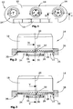
- Fig. 1 is shown in plan view, the front panel 10 of an operating unit 12 for an air conditioning or heating system of a motor vehicle. Shown are three turntable 14 for adjusting the temperature, the air distribution and the blower power. Furthermore, the operating unit 12 has various pushbuttons 16. The three turntable 14 have locking devices on the one hand to maintain the currently occupied rotational position and on the other hand to the acoustic and tactile feedback of an adjustment to the person using a turntable.
- the structure of the latching device according to a first embodiment will be described below with reference to FIGS. 2 to 11 described in more detail.
- Each turntable 14 has a rotary control element 18 which is rotatably mounted about an axis of rotation 20.
- the rotary control element 18 At the lower axial end face 22, the rotary control element 18 on a detent gate 24, the front side along the circumference of the rotary control element 18 extends and consists of alternately arranged detent recesses 26 and increments 28.
- These latching recesses 26 and grid increments 28 form a latching track 30, along which a resiliently mounted latching projection 32 slides when the rotary control element 18 is actuated, that is rotated.
- the locking projection 32 is formed as a bead-shaped projection of an annular spring 34 in this embodiment, which is fixed to two diametrically opposed fixing portions 35 on the housing 36 of the control unit 12.
- the FIGS. 2 and 3 show how the locking projection 32 moves up and down when the rotary control element 18 is rotated.
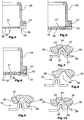
- FIGS. 2 and 3 The peculiarity of the locking device according to the FIGS. 2 and 3 is to be seen in a periodic change in inclination of the surfaces of the detent recesses 26 and grid increments 28. This is in the FIGS. 4 to 6 made clear. Based on Fig. 4 It can be seen that the latching recesses 26 at its lowest point 37 have a different inclination, as the grid increments 28 at their vertices 38. This is because the latching projection 32 along a line of contact 40 against the latching track 30 abuts (see Fig. 6 ). In arrangement the latching projection 32 in a latching recess 26, the contact along two contact lines 42, as in Fig. 7 is shown.
- FIGS. 8 to 10 are single phases when immersing the locking projection 32 shown in a detent recess 26. It can be seen that the latching projection 32 rests against the latching track 30 only in its position immersed deepest in the latching recess 26 along two contact lines. By contacting along the line zones remains for shock pulses that the locking projection 32 exerts on the latching track 30, less energy, which has the consequence that the noise and the reverberation are reduced.
- the radius of the locking projection should be greater than the radius of a detent recess.
- the locking projection may not contact the detent recess in the region of its vertex when the detent projection is immersed at most deeply into the detent recess.
- Fig. 11 is a perspective view of the annular spring 34 is shown. Indicated in Fig. 11 in that the latching projection 32 is formed as a bead, which forms a truncated cone part surface. The truncated cone part surface is inclined to the center of the annular spring 34.
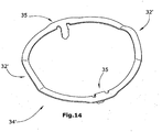
- FIGS. 12 to 14 is a second embodiment of a locking device comprising a detent spring with locking projection and a detent gate shown in the turntable 14 according to Fig. 2 can be used.
- Fig. 12 is the detent gate 24 'again formed substantially wave-shaped, however, has individual flat surface sections 50,52 and 54 on.
- 50 the reason of a detent recess 26 'forming surface portions are designated, while the surface portions 52 and 54 form the two-sided flanks of a detent recess 26'.
- the two-sided flanks 52, 54 extend up to the apex points 38 'of the grid increments 28' and are inclined to the center or to the axis of rotation 20 'of the rotary control element.
- the surface portions 50, 52 and 54 are arranged similarly to the side surfaces of a pyramid having a polygonal (more than four-cornered) base.
- the annular spring 34 ' has a latching projection 32', which extends uniformly arcuate and has a radius, so that the latching projection 32 'covers a latching recess 26'.
- the shape of the bead-shaped locking projection 32 ' is in turn frustoconical surface.
- the same applies to the dipping process of the locking projection 32 'in a detent recess 26' which above in connection with the description of FIGS. 8 to 10 is executed.
Landscapes
- Engineering & Computer Science (AREA)
- Radar, Positioning & Navigation (AREA)
- Remote Sensing (AREA)
- Physics & Mathematics (AREA)
- General Physics & Mathematics (AREA)
- General Engineering & Computer Science (AREA)
- Computer Networks & Wireless Communication (AREA)
- Automation & Control Theory (AREA)
- Acoustics & Sound (AREA)
- Mechanical Engineering (AREA)
- Rotary Switch, Piano Key Switch, And Lever Switch (AREA)
- Lock And Its Accessories (AREA)
- Mechanical Control Devices (AREA)
- Bearings For Parts Moving Linearly (AREA)
Description
- Die Erfindung betrifft eine Rastvorrichtung für ein rotatorisch oder translatorisch bewegbares Bedienelement.
- Zur manuellen Bedienung elektrischer bzw. elektronischer Geräte dienen Bedieneinheiten, die Bedienelemente in unterschiedlichsten Ausgestaltungen aufweisen. Neben niederdrückbaren Tasten-Bedienelementen, Schiebern o.dgl. werden in zunehmendem Maße insbesondere bei Fahrzeug-Bedieneinheiten sogenannte Drehsteller, also drehbare Bedienelemente eingesetzt. Bei drehbaren sowie bei translatorisch bewegbaren Bedienelementen ist es wünschenswert, der das Bedienelemente betätigenden Person eine akustische und/oder taktile Rückmeldung bezügliche einer vorgenommenen Verstellung des Bedienelements zu geben. Diesbezüglich haben sich Rastvorrichtungen bewährt, die darüber hinaus den Vorteil haben, dass das Bedienelement die einmal eingenommene Verstellposition selbsttätig hält. Rastvorrichtungen erzeugen darüber hinaus ein mehr oder weniger deutlich wahrnehmbares Rastgeräusch und liefern eine taktile Rückmeldung an die das Bedienelement betätigende Person.
- Rastvorrichtungen für Bedienelemente der vorstehend genannten Art sind beispielsweise in
DE 10 2007 013 383 B3 ,DE 10 2006 036 636 A1 , welche den nächstliegenden Stand der Technik bildet,DE 102 36 066 A1 undDE 103 23 544 A1 beschrieben. - Die bekannten Rastvorrichtungen arbeiten mit einem federelastisch gelagerten Rastvorsprung, der in Gleitkontakt mit einer Rastkulisse steht, die mehrere Rastmulden mit zwischen diesen angeordneten Rasterhöhungen aufweist. Die Rastkulisse ist im Regelfall als wellenförmige Rastbahn ausgebildet, die eine kontinuierliche durchgehende Oberfläche oder aber abschnittsweise plane (Facetten-)Flächen aufweist.
- Auf Grund seiner elastischen Lagerung führt der Rastvorsprung beim Gleiten über die Rastbahn Auf- und Abbewegungen aus. Normalerweise ist der Rastvorsprung Teil eines Federarms,. der bei Betrachtung auf die Rastkulisse außerhalb derselben gelagert ist. Bei einer derartigen Anordnung verändert sich die Ausrichtung der Oberfläche des Rastvorsprungs relativ zur Oberfläche der Rastbahn, wenn der Rastvorsprung bei Betätigung des Bedienelements über die Rastkulisse entlang gleitet.
- Die Oberfläche der Rastvorsprünge ist im Allgemeinen sphärisch ausgebildet. Darüber hinaus ist der Berührungskontakt des Rastvorsprungs mit der Rastkulisse herkömmlicherweise als punktförmige Kontaktzone ausgeführt. Der Rastvorsprung besteht zumeist aus Metall und ist sickenförmig, während die Rastkulisse im Regelfall aus Kunststoff besteht. Damit ist die Rastkulisse einem Verschleiß durch den auf ihr entlanggleitenden Rastvorsprung ausgesetzt. Diesen Verschleißerscheinungen versucht man durch Auftragen von Schmiermitteln (wie z.B. Fett) entgegenzuwirken.
- Das Rastgeräusch entsteht durch die impulsförmige Kontaktierung des Rastvorsprungs mit der Rastkulisse, wenn sich beide relativ zueinander bewegen, was im Falle der Betätigung des Bedienelements gegeben ist. Das Rastgeräusch kann nur bedingt beeinflusst werden, was recht aufwendig ist.
- Aufgabe der Erfindung ist es, eine Rastvorrichtung für ein rotatorisch oder translatorisch bewegbares Bedienelement zu schaffen, das sich durch einen geringeren Verschleiß und eine damit erhöhte Dauerlauffestigkeit und durch reduzierte Geräusche bzw. beeinflussbare Geräusche auszeichnet.
- Zur Lösung dieser Aufgabe wird mit der Erfindung eine Rastvorrichtung für ein rotatorisch oder translatorisch bewegbares Bedienelement vorgeschlagen, wobei die Rastvorrichtung versehen ist mit den Merkmalen des Anspruchs 1. Die Unteransprüche beziehen sich auf verschiedene Ausgestaltungen der Erfindung.
- Ein wesentliches Merkmal der erfindungsgemäßen Rastvorrichtung ist darin zu sehen, dass der Rastvorsprung mit der Rastbahn, also mit der Oberseite der Rastkulisse, längs mindestens einer Linienzone bzw. Linie in Kontakt steht. Dieser Linienkontakt bzw. jeder Linienkontakt erstreckt sich dabei im Wesentlichen quer zur Erstreckung der Rastbahn. Hierzu weist der Rastvorsprung eine Oberfläche auf, die die Rastbahn längs mindestens einer im Wesentlichen quer zur Längserstreckung der Rastbahn. verlaufenden Kontaktlinie berührt. Diese Berührung längs einer Kontaktlinie gilt vor allem dann, wenn sich der Rastvorsprung außerhalb seines am weitesten in einer Rastmulde eingetauchten Zustandes befindet. Wenn er am weitesten in die Rastmulde eingetaucht ist, kontaktiert der Rastvorsprung die Oberfläche der Rastbahn vorzugsweise.längs zweier Kontaktlinien der zuvor beschriebenen Art, und zwar beidseitig des tiefsten Rastmuldenpunktes an den gegenüberliegenden Flanken, die von dem tiefsten Punkt der Rastmulde aus zu den höchsten Punkten (Scheitelpunkten) der jeweils benachbarten Rasterhöhungen führen.
- Der Rastvorsprung vollführt beim Gleiten über die Rastbahn eine Auf- und Abbewegung unter periodischer Veränderung der Neigung seiner Kontaktlinie zur Rastkulisse. Damit nun diese Kontaktlinie als Linienkontakt zwischen dem Rastvorsprung und der Rastkulisse stets beibehalten bleibt, ist erfindungsgemäß vorgesehen, dass die Oberfläche der Rastbahn eine der Veränderung der Ausrichtung der Kontaktlinie des Rastvorsprungs bei dessen Auf- und Abbewegung folgenden Neigungsveränderung aufweist.
- Durch die erfindungsgemäße Ausgestaltung der Neigungen der Oberfläche der Rastbahn in Relation zur veränderten Neigung der Oberfläche des Rastvorsprungs bei dessen Auf- und Abbewegung über die Rastkulisse wird für einen dauerhaften Linienkontakt zwischen dem Rastvorsprung und der Rastkulisse gesorgt. Dies führt zu einer geringeren Flächenpressung zwischen Rastvorsprung und Rastkulisse bzw. Rastbahn. Damit besteht die Möglichkeit, die Rastkulisse aus einem verschleißanfälligeren Kunststoffmaterial bzw. aus einem Kunststoffmaterial ohne verschleißmindernde Zusatzstoffe herzustellen. Das wiederum erlaubt es, die Bauteilkosten zu reduzieren. Anders ausgedrückt kann bei gegenüber herkömmlichen Rastvorrichtungen unveränderter Materialauswahl eine höhere Lebensdauerfestigkeit und damit eine erhöhte Dauerlauffestigkeit erreicht werden. Durch die Linienberührung wird darüber hinaus eine stabilere Ruhelage erwirkt. Damit aber wiederum kann die vorspannkraft, mit der der Rastvorsprung gegen die Rastkulisse drückt, verringert werden, was wiederum verschleißmindernd und geräuschreduzierend wirkt.
- Durch die Beibehaltung des Linienkontakts beim Gleiten des Rastvorsprungs über die. Rastkulisse erfolgt insgesamt eine Reduzierung der Stoßimpulse, wie sie der Rastvorsprung auf die Rastkulisse bewirkt. Die Reduzierung der Stoßimpulse führt neben einer Verschleißreduktion auch zu einer Geräuschreduktion, und zwar ohne dass, wie es bisher üblich ist, im Rastsystem zusätzliche Hilfsmittel wie beispielsweise Schmierstoffe, Fette o.dgl. verwendet werden müssen. Schließlich bewirkt die erfindungsgemäße Konstruktion auch eine Vergrößerung des Verlustfaktors (Dämpfungsfaktors) sowie eine Verringerung der Nachhallzeit. All dies wirkt sich auf die Performance und insbesondere auf die Haptik und Akustik der Rastvorrichtung vorteilhaft aus. Anders ausgedrückt ist es durch den erfindungsgemäßen Ansatz möglich, Einfluss zu nehmen auf eine Reduzierung des Verschleißes und auf die Akustik, die eine Rastvorrichtung in sich birgt.
- In vorteilhafter Ausgestaltung der Erfindung kann vorgesehen sein, dass die bezüglich ihrer Neigung sich verändernde Oberfläche der Rastbahn zwischen den Scheitelpunkten zweier benachbarter Rasterhöhungen als Kegelstumpfteilfläche ausgebildet ist. Alternativ dazu ist es möglich, die Kegelstumpfteilflächen durch ebene Teilflächen zu ersetzen, und zwar ähnlich den Seitenflächen einer Pyramide mit einer vieleckigen (mehr als vier Ecken aufweisenden) Grundfläche. Die Achse des Kegelstumpfes bzw. der Pyramide verläuft dabei im Wesentlichen quer zur Erstreckung der Rastbahn. Bei Ausbildung der Rastmulden in Form ebener unterschiedlich geneigter Teilflächen umfassen diese eine den Grund der Rastmulde bildende erste Fläche und zwei beidseitig dieser ersten Fläche angeordnete zweite Flanken- bzw. Schrägflächen, die zur Seite gekippt bzw. geneigt sind.
- Wie bereits oben erwähnt, ist der Rastvorsprung vorzugsweise als Sicke an einem (metallischen) Federarm ausgebildet, dessen eines Ende fixiert ist und an dessen anderen Ende der Rastvorsprung angeordnet ist. Ein derartiger Federarm, der im Wesentlichen quer zur Erstreckung der Rastbahn ausgerichtet ist, durchbiegt sich elastisch beim Auf- und Abbewegen seines Rastvorsprungs zwischen seinem fixierten Ende und dem Rastvorsprung.
- Bei einem Federarm der zuvor genannten Art ist die den Rastvorsprung bildende Sicke im Wesentlichen kegelstumpfteilflächenartig ausgebildet, wobei die Kegelachse im Wesentlichen quer zum Verlauf der Rastbahn und damit im Wesentlichen in Richtung des Federarms verläuft.
- Als Federarm kann aber auch eine ringförmige Struktur gewählt werden. Dabei folgt der ringförmige Federarm dem Verlauf der Rastbahn im Wesentlichen (bei Draufsicht auf die Rastbahn betrachtet). Derartige Ringfedern werden bevorzugt eingesetzt. Sie weisen im Allgemeinen zwei diametral gegenüberliegend angeordnete Fixierbereiche auf, wobei um 90° versetzt zu diesen Fixierbereichen mindestens ein Rastvorsprung oder zwei Rastvorsprünge ausgebildet ist bzw. sind. Dieser bzw. jeder Rastvorsprung weist bei dieser Weiterbildung der Erfindung eine kegelstumpfteilflächenähnliche Sicke mit einer radial zur Ringform des Federarms verlaufenden Kegelachse auf.
- Die Erfindung wird nachfolgend anhand zweier Ausführungsbeispiele sowie unter Bezugnahme auf die Zeichnung näher erläutert. Im Einzelnen zeigen dabei:
- Fig. 1
- eine Ansicht auf die Vorderseite einer Heizungsanlagen-Bedieneinheit für ein Fahrzeug,
- Fig. 2
- eine Schnittansicht entlang der Linie II-II der
Fig. 1 zur Darstellung der Rastvorrichtung in Seitenansicht, und zwar in der Position, in der der Rastvorsprung in eine Rastmulde eingetaucht ist, - Fig. 3
- eine Schnittdarstellung ähnlich der gemäß
Fig. 2 jedoch in der derjenigen Stellung des Drehbedienelements, in der der Rastvorsprung eine Rasterhöhung der Rastvorrichtung kontaktiert, - Fig. 4
- eine Schnittansicht entlang der Linie IV-IV der
Fig. 2 , jedoch ohne dass die Rastfeder dargestellt ist, - .Fign. 5 und 6
- Schnittansichten entlang der Linie IV-IV und V-V der
Fign. 2 und 3 , - Fig. 7
- eine vergrößerte Darstellung des in
Fig. 2 bei VII gekennzeichneten Bereichs zur Verdeutlichung, dass der Rastvorsprung in einer Rastvertiefung die Rastkulisse längs zweier Kontaktlinien berührt, - Fign. 8 bis 10.
- die jeweiligen Kontaktierungen von Rastvorsprung und Rastkulisse beim Eintauchen des Rastvorsprungs in eine Rastvertiefung,
- Fig. 11
- eine perspektivische Darstellung einer ringförmigen Rastfeder mit kegelstumpfteilflächenartiger Ausgestaltung der Rastvorsprungssicke,
- Fig. 12
- eine Darstellung ähnlich der gemäß
Fig. 2 jedoch bei einer alternativ ausgebildeten Rastvorrichtung, - Fig. 13
- eine perspektivische Darstellung der Oberseite der Rastkulisse beim Ausführungsbeispiel der Rastvorrichtung gemäß
Fig. 12 und - Fig. 14
- eine perspektivische Darstellung der im Ausführungsbeispiel gemäß
Fig. 12 verwendbaren Rastfeder mit Rastvorsprung. - In
Fig. 1 ist in Draufsicht die Frontblende 10 einer Bedieneinheit 12 für eine Klima- bzw. Heizungsanlage eines Kraftfahrzeuges gezeigt. Dargestellt sind drei Drehsteller 14 zur Einstellung der Temperatur, der Luftverteilung und der Gebläsestärke. Ferner weist die Bedieneinheit 12 verschiedene Drucktasten 16 auf. Die drei Drehsteller 14 verfügen über Rastvorrichtungen einerseits zur Beibehaltung der aktuell eingenommenen Drehposition und andererseits zur akustischen und taktilen Rückmeldung einer Verstellung an die einen Drehsteller bedienenden Person. Der Aufbau der Rastvorrichtung gemäß einem ersten Ausführungsbeispiel wird nachfolgend anhand derFign. 2 bis 11 näher beschrieben. - Jeder Drehsteller 14 weist ein Drehbedienelement 18 auf, das um eine Drehachse 20 drehbar gelagert ist. An der unteren axialen Stirnseite 22 weist das Drehbedienelement 18 eine Rastkulisse 24 auf, die stirnseitig längs des Umfangs des Drehbedienelements 18 verläuft und aus wechselweise angeordneten Rastmulden 26 und Rasterhöhungen 28 besteht. Diese Rastmulden 26 und Rasterhöhungen 28 bilden eine Rastbahn 30, entlang derer ein federelastisch gelagerter Rastvorsprung 32 gleitet, wenn das Drehbedienelement 18 betätigt, d.h. gedreht wird. Der Rastvorsprung 32 ist als sickenförmiger Vorsprung einer in diesem Ausführungsbeispiel ringförmigen Feder 34 ausgebildet, die an zwei diametral gegenüberliegenden Fixierbereichen 35 am Gehäuse 36 der Bedieneinheit 12 fixiert ist. Die
Fign. 2 und 3 zeigen, wie sich der Rastvorsprung 32 auf- und abbewegt, wenn das Drehbedienelement 18 gedreht wird. - Die Besonderheit der Rastvorrichtung gemäß den
Fign. 2 und 3 ist in einer periodischen Neigungsveränderung der Oberflächen der Rastmulden 26 sowie Rasterhöhungen 28 zu sehen. Dies ist in denFign. 4 bis 6 deutlich gemacht. Anhand vonFig. 4 ist zu erkennen, dass die Rastmulden 26 an ihrem tiefsten Punkt 37 eine andere Neigung aufweisen, als die Rasterhöhungen 28 an ihren Scheitelpunkten 38. Dies ist deshalb gegeben, weil der Rastvorsprung 32 längs einer Kontaktlinie 40 an der Rastbahn 30 anliegt (sieheFig. 6 ). Bei Anordnung des Rastvorsprungs 32 in einer Rastmulde 26 erfolgt der Kontakt längs zweier Kontaktlinien 42, wie es inFig. 7 gezeigt ist. - Wie anhand von
Fig. 6 zu erkennen ist, verändert sich die Ausrichtung der Oberfläche 44 des Rastvorsprungs 32, wenn dieser entlang der Rastbahn 30 gleitet. Die Neigung der Rastbahn 30 folgt nun dieser veränderten Ausrichtung der Rastvorsprungsoberfläche 44. Damit ist gewährleistet, dass der Rastvorsprung 32 stets Linienkontakt zur Rastbahn 30 hat. Dies wiederum wirkt sich insbesondere verschleißmindernd und geräuschverringernd aus. - In den
Fign. 8 bis 10 sind einzelne Phasen beim Eintauchen des Rastvorsprungs 32 in eine Rastmulde 26 gezeigt. Zu erkennen ist, dass der Rastvorsprung 32 ausschließlich in seiner am tiefsten in die Rastmulde 26 eingetauchten Position längs zweier Kontaktlinien an der Rastbahn 30 anliegt. Durch die Kontaktierung längs der Linienzonen verbleibt für Stoßimpulse, die der Rastvorsprung 32 auf die Rastbahn 30 ausübt, weniger Energie, was zur Folge hat, dass auch die Geräuschentwicklung und der Nachhall reduziert sind. - Damit es erst bei Erreichen der am weitesten in die Rastmulde eingetauchten Position des Rastvorsprungs zu einer Kontaktierung längs zweier Kontaktlinien mit der Rastbahn kommt, sollte der Radius des Rastvorsprungs größer sein als der Radius einer Rastmulde. Mit anderen Worten darf der Rastvorsprung im Bereich seines Scheitelpunktes die Rastmulde nicht kontaktieren, wenn der Rastvorsprung maximal tief in die Rastmulde eingetaucht ist.
- In
Fig. 11 ist eine perspektivische Ansicht auf die Ringfeder 34 dargestellt. Angedeutet ist inFig. 11 , dass der Rastvorsprung 32 als Sicke ausgebildet ist, die eine Kegelstumpfteilfläche bildet. Die Kegelstumpfteilfläche ist zum Mittelpunkt der Ringfeder 34 geneigt. - In den
Fign. 12 bis 14 ist ein zweites Ausführungsbeispiel einer Rastvorrichtung umfassend eine Rastfeder mit Rastvorsprung und eine Rastkulisse gezeigt, die beim Drehsteller 14 gemäßFig. 2 eingesetzt werden kann. - Gemäß
Fig. 12 ist die Rastkulisse 24' wiederum im Wesentlichen wellenförmig ausgebildet, weist allerdings einzelne ebene Flächenabschnitte 50,52 und 54 auf. Mit 50 sind die den Grund einer Rastmulde 26' bildenden Flächenabschnitte bezeichnet, während die Flächenabschnitte 52 und 54 die beidseitigen Flanken einer Rastmulde 26' bilden. Die beidseitigen Flanken 52,54 erstrecken sich bis zu den Scheitelpunkten 38' der Rasterhöhungen 28' und sind zum Mittelpunkt bzw. zur Drehachse 20' des Drehbedienelements geneigt. Damit sind die Flächenabschnitte 50,52 und 54 ähnlich den Seitenflächen einer Pyramide mit einer vieleckigen (mehr als vier Ecken aufweisenden) Grundfläche angeordnet. Die Ringfeder 34' weist einen Rastvorsprung 32' auf, der gleichmäßig bogenförmig verläuft und einen Radius aufweist, so dass der Rastvorsprung 32' eine Rastmulde 26' überdeckt. Die Form des sickenförmig ausgebildeten Rastvorsprungs 32' ist wiederum kegelstumpfteilflächenförmig. Es gilt auch wiederum, dass der Rastvorsprung 32' bei zentrischer Anordnung in einer Rastmulde 26' die Rastbahn 30' längs zweier Kontaktlinien 42' kontaktiert. Außerhalb des Zentrums einer Rastmulde 26' kontaktiert der Rastvorsprung 32' die Rastbahn 30' längs lediglich einer Kontaktlinie. Damit gilt für den Eintauchvorgang des Rastvorsprungs 32' in eine Rastmulde 26' das Gleiche, was oben im Zusammenhang mit der Beschreibung derFign. 8 bis 10 ausgeführt ist. - Vorstehend wurden zwei Ausgestaltungen von Rastvorrichtungen beschrieben, und zwar anhand eines rotatorisch bewegbaren Drehbedienelements. Es sei an dieser Stelle darauf hingewiesen, dass die zuvor beschriebenen Rastvorrichtungen auch bei einem translatorisch bewegbaren Bedienelement eingesetzt werden können. Auch hier verändert sich die Neigung der Kontaktlinie zwischen Rastvorsprung und Rastbahn periodisch, wenn der Rastvorsprung entlang der Rastbahn gleitet. Zur Verschleiß- und Geräuschminimierung werden dann die gleichen Mechanismen genutzt, wie sie weiter oben im Zusammenhang mit den beiden beschriebenen Ausführungsbeispielen erläutert worden sind.
-
- 10
- Frontblende einer Bedieneinheit
- 12
- Bedieneinheit
- 14
- Drehsteller der Bedieneinheit
- 16
- Drucktasten der Bedieneinheit
- 18
- Drehbedienelement des Drehstellers
- 20
- Drehachse des Drehbedienelements
- 20'
- Drehachse des Drehbedienelements
- 22
- Stirnseite des Drehbedienelements
- 24
- Rastkulisse
- 24'
- Rastkulisse
- 26
- Rastmulden der Rastkulisse
- 26'
- Rastmulden der Rastkulisse
- 28
- Rasterhöhungen der Rastkulisse
- 28'
- Rasterhöhungen der Rastkulisse
- 30
- Rastbahn aus Rastmulden und Rasterhöhungen
- 30'
- Rastbahn aus Rastmulden und Rasterhöhungen
- 32
- Rastvorsprung
- 32'
- Rastvorsprung
- 34
- Ringfeder mit Rastvorsprung
- 34'
- Ringfeder mit Rastvorsprung
- 35
- Fixierbereich für Ringfeder
- 36
- Gehäuse der Bedieneinheit
- 37
- tiefster Punkt einer Rastmulde
- 38
- Scheitelpunkt einer Rasterhöhung
- 38'
- Scheitelpunkt einer Rasterhöhung
- 40
- Kontaktlinie
- 42
- Kontaktlinie
- 42'
- Kontaktlinie
- 44
- Rastvorsprungsoberfläche
- 50
- tiefster Flächenabschnitt einer Rastmulde
- 52
- Flanken-Flächenabschnitt einer Rastmulde
- 54
- Flanken-Flächenabschnitt einer Rastmulde
Claims (6)
- Rastvorrichtung für ein rotatorisch oder translatorisch bewegbares Bedienelement, mit- einem federelastisch gelagerten Rastvorsprung (32,32') und- einer in Gleitkontakt mit dem Rastvorsprung (32,32') stehenden Rastkulisse (24,24'), die mehrere Rastmulden (26,26') mit zwischen diesen angeordneten Rasterhöhungen aufweist,- wobei die Rastmulden (26,26') und die Rasterhöhungen (28,28') eine im Wesentlichen wellenförmige Rastbahn (30,30') bilden, die ober- und unterhalb einer Rastbahnerstreckungsebene verläuft und auf der der Rastvorsprung (32,32') bei einer Relativbewegung von Rastkulisse (24) und Rastvorsprung (32,32') entlang gleitet, und- wobei der Rastvorsprung (32,32') eine Oberfläche (44) aufweist, die die Rastbahn (30,30') längs mindestens einer im Wesentlichen quer zur Längserstreckung der Rastbahn (30,30') verlaufenden Kontaktlinie (40,42,40',42') berührt,dadurch gekennzeichnet,- dass der Rastvorsprung (32,32') beim Gleiten entlang der Rastbahn (30,30') eine Auf- und Abbewegung unter periodischer Veränderung der Neigung seiner Kontaktlinie (40,42,40',42') zur Rastbahnerstreckungsebene erfährt und- dass die Oberfläche der Rastbahn (30,30') eine der Neigungsveränderung der Kontaktlinie (40,42,40',42') des Rastvorsprungs (32,32') bei dessen Auf- und Abbewegung folgende Veränderung der Neigung zur Rastbahnerstreckungsebene aufweist.
- Rastvorrichtung nach Anspruch 1, dadurch gekennzeichnet, dass die Oberfläche (44) der Rastbahn (30,30') zwischen den Scheitelpunkten (38) zweier benachbarter Rasterhöhungen (28,28') als Kegelstumpfteilfläche oder als teilpyramidenartige Fläche mit quer zur Erstreckung der Rastbahn (30,30') verlaufender Kegel- bzw. Pyramidenachse ausgebildet ist.
- Rastvorrichtung nach Anspruch 1 oder 2, dadurch gekennzeichnet, dass der Rastvorsprung (32,32') an einem Federarm (34,34') ausgebildet ist, dass der Federarm (34,34') an mindestens einem Ende fixiert und der Rastvorsprung (32,32') beabstandet dazu angeordnet ist und dass sich der Federarm (34,34') zwischen seinem fixierten Ende und dem Rastvorsprung (32,32') beim Auf- und Abbewegen des Rastvorsprungs (32,32') bogenförmig verformt.
- Rastvorrichtung nach Anspruch 3, dadurch gekennzeichnet, dass der Federarm (34,34') - in der Draufsicht auf die Rastbahn (30,30') betrachtet - im Wesentlichen geradlinig und rechtwinklig zur Ausrichtung der Rastbahn (30,30') verläuft und dass der Rastvorsprung (32,32') als kegelstumpfteilflächenförmige Sicke mit einer im Wesentlichen in Erstreckung des Federarms (34,34') verlaufenden Kegelachse ausgebildet ist.
- Rastvorrichtung nach Anspruch 4, dadurch gekennzeichnet, dass der Federarm (34,34') - in der Draufsicht auf die Rastbahn (30,30') betrachtet - der Rastbahn (30,30') folgend ringförmig verläuft, dass der bogenförmige Federarm (34,34') an seinen beiden aneinander abgewandten Enden fixiert ist und dass der Rastvorsprung (32,32') im Wesentlichen im Bereich des Scheitelpunkts (38) des bogenförmigen Federarms (34,34') angeordnet und als kegelstumpfteilflächenförmige Sicke mit einer radial zur Ringform des Federarms verlaufenden Kegelachse ausgebildet ist.
- Rastvorrichtung nach Anspruch 5, dadurch gekennzeichnet, dass die Rastkulisse (24,24') entlang einer Kreislinie verläuft und dass der Federarms (34,34') als Ringfeder mit einem Rastvorsprung (32,32') oder mit zwei diametral angeordneten Rastvorsprüngen (32,32') und zwei gegenüber jedem Rastvorsprung (32,32') um 90° versetzt angeordneten Fixierbereichen ausgebildet ist.
Applications Claiming Priority (2)
| Application Number | Priority Date | Filing Date | Title |
|---|---|---|---|
| DE102011087829.7A DE102011087829B4 (de) | 2011-12-06 | 2011-12-06 | Rastvorrichtung für ein rotatorisch oder translatorisch bewegbares Bedienelement |
| PCT/EP2012/074340 WO2013083554A2 (de) | 2011-12-06 | 2012-12-04 | Rastvorrichtung für ein rotatorisch oder translatorisch bewegbares bedienelement |
Publications (2)
| Publication Number | Publication Date |
|---|---|
| EP2788833A2 EP2788833A2 (de) | 2014-10-15 |
| EP2788833B1 true EP2788833B1 (de) | 2017-08-02 |
Family
ID=47297253
Family Applications (1)
| Application Number | Title | Priority Date | Filing Date |
|---|---|---|---|
| EP12797882.3A Active EP2788833B1 (de) | 2011-12-06 | 2012-12-04 | Rastvorrichtung für ein rotatorisch oder translatorisch bewegbares bedienelement |
Country Status (7)
| Country | Link |
|---|---|
| US (1) | US9651108B2 (de) |
| EP (1) | EP2788833B1 (de) |
| KR (1) | KR101617982B1 (de) |
| CN (1) | CN104011615B (de) |
| DE (1) | DE102011087829B4 (de) |
| ES (1) | ES2644135T3 (de) |
| WO (1) | WO2013083554A2 (de) |
Families Citing this family (8)
| Publication number | Priority date | Publication date | Assignee | Title |
|---|---|---|---|---|
| DE102014201517A1 (de) | 2014-01-28 | 2015-07-30 | Behr-Hella Thermocontrol Gmbh | Rastvorrichtung für ein rotatorisch oder translatorisch bewegbares Bedienelement |
| EP3100128A2 (de) * | 2014-01-30 | 2016-12-07 | Behr-Hella Thermocontrol GmbH | Rastvorrichtung für ein rotatorisch oder translatorisch bewegbares bedienelement |
| DE202014011130U1 (de) * | 2014-05-09 | 2018-01-14 | Trw Automotive Electronics & Components Gmbh | Federring für einen indexierten Drehschalter und indexierter Drehschalter |
| DE102016115548B4 (de) * | 2016-08-22 | 2022-01-05 | Bcs Automotive Interface Solutions Gmbh | Indexierter Drehschalter |
| WO2018053875A1 (zh) | 2016-09-26 | 2018-03-29 | 深圳市大疆创新科技有限公司 | 拨轮机构及使用该拨轮机构的控制装置 |
| DE102020114634B4 (de) * | 2019-07-18 | 2023-07-20 | Defond Components Limited | Steuerbaugruppe zur Verwendung mit einem Elektrogerät sowie ein entsprechendes Elektrogerät |
| US11469061B2 (en) * | 2020-02-26 | 2022-10-11 | GE Precision Healthcare LLC | Control device sensor rotation |
| DE102024202985A1 (de) * | 2024-03-28 | 2025-10-02 | BSH Hausgeräte GmbH | Haushaltsgerät-Bedienvorrichtung mit einem Ring als Bedienelement und damit gekoppelter Textdarstellung, Haushaltsgerät sowie Verfahren |
Family Cites Families (14)
| Publication number | Priority date | Publication date | Assignee | Title |
|---|---|---|---|---|
| FR1439874A (fr) * | 1964-12-31 | 1966-05-27 | Perfectionnements aux contacteurs rotatifs à plots | |
| JPH08222413A (ja) * | 1995-02-14 | 1996-08-30 | Matsushita Electric Ind Co Ltd | クリック装置 |
| JP3458550B2 (ja) * | 1995-08-21 | 2003-10-20 | 松下電器産業株式会社 | クリック機構 |
| JP3505300B2 (ja) * | 1995-10-31 | 2004-03-08 | アルプス電気株式会社 | 車載用回転検出装置 |
| DE10236066B4 (de) * | 2002-08-07 | 2009-01-15 | Preh Gmbh | Bedienelement mit einer mechanischen Rastung |
| DE10305668A1 (de) * | 2002-09-24 | 2004-03-25 | Behr-Hella Thermocontrol Gmbh | Betätigungseinrichtung sowie Verwendung derselben |
| DE10323544B4 (de) * | 2003-05-24 | 2005-10-27 | Preh Gmbh | Rasteinrichtung für ein dreheinstellbares, elektrisches Bauelement |
| DE102006036636B4 (de) * | 2005-08-03 | 2010-08-19 | Preh Gmbh | Rasteinrichtung für ein Bedienelement in einem Kraftfahrzeug |
| US7767916B2 (en) * | 2006-06-30 | 2010-08-03 | Kabushiki Kaisha Tokai Rika Denki Seisakusho | Switch device |
| US7804036B2 (en) * | 2007-02-20 | 2010-09-28 | Kabushiki Kaisha Tokai Rika Denki Seisakusho | Control switch apparatus |
| DE102007013383B3 (de) * | 2007-03-16 | 2008-09-04 | Preh Gmbh | Bedienelement mit mechanischer Rastung |
| JP4910883B2 (ja) * | 2007-05-25 | 2012-04-04 | パナソニック株式会社 | クリック付き回転操作型電子部品 |
| JP2009099296A (ja) * | 2007-10-15 | 2009-05-07 | Panasonic Corp | クリック装置 |
| DE102009048330A1 (de) * | 2009-10-06 | 2011-04-07 | Behr-Hella Thermocontrol Gmbh | Bedieneinheit für eine Fahrzeugkomponente, insbesondere eine Belüftungs-, Heizungs- und/oder Klimaanlage |
-
2011
- 2011-12-06 DE DE102011087829.7A patent/DE102011087829B4/de not_active Expired - Fee Related
-
2012
- 2012-12-04 KR KR1020147018655A patent/KR101617982B1/ko active Active
- 2012-12-04 ES ES12797882.3T patent/ES2644135T3/es active Active
- 2012-12-04 CN CN201280060114.4A patent/CN104011615B/zh active Active
- 2012-12-04 EP EP12797882.3A patent/EP2788833B1/de active Active
- 2012-12-04 WO PCT/EP2012/074340 patent/WO2013083554A2/de not_active Ceased
- 2012-12-04 US US14/362,672 patent/US9651108B2/en active Active
Non-Patent Citations (1)
| Title |
|---|
| None * |
Also Published As
| Publication number | Publication date |
|---|---|
| DE102011087829A1 (de) | 2013-06-06 |
| WO2013083554A3 (de) | 2013-09-12 |
| ES2644135T3 (es) | 2017-11-27 |
| US20140360313A1 (en) | 2014-12-11 |
| CN104011615A (zh) | 2014-08-27 |
| KR101617982B1 (ko) | 2016-05-03 |
| US9651108B2 (en) | 2017-05-16 |
| CN104011615B (zh) | 2016-02-10 |
| EP2788833A2 (de) | 2014-10-15 |
| DE102011087829B4 (de) | 2015-08-06 |
| WO2013083554A2 (de) | 2013-06-13 |
| KR20140109413A (ko) | 2014-09-15 |
Similar Documents
| Publication | Publication Date | Title |
|---|---|---|
| DE102011087829B4 (de) | Rastvorrichtung für ein rotatorisch oder translatorisch bewegbares Bedienelement | |
| EP2534549B1 (de) | Drehsteller | |
| DE202015101932U1 (de) | Steuerungsvorrichtung zum Steuern von Einrichtungen per Hand | |
| DE19514653A1 (de) | Schalterbetätigungsanordnung | |
| DE102020126785A1 (de) | Drehanschlagvorrichtung | |
| EP1795990A1 (de) | Bedieneinheit für eine Fahrzeugkomponente | |
| DE102008014566B4 (de) | Bedieneinheit für eine Fahrzeugkomponente, insbesondere für eine Belüftungs- und/oder Klimaanlage | |
| DE102009048330A1 (de) | Bedieneinheit für eine Fahrzeugkomponente, insbesondere eine Belüftungs-, Heizungs- und/oder Klimaanlage | |
| DE10228589A1 (de) | Schalter, insbesondere Drehschalter | |
| WO2018196916A1 (de) | Kugelgewindetrieb | |
| DE102014201517A1 (de) | Rastvorrichtung für ein rotatorisch oder translatorisch bewegbares Bedienelement | |
| DE3442173A1 (de) | Elektrischer schalter gedrungener bauart | |
| DE102004031586A1 (de) | Spieloptimierte Aufnahme für Schaltstück | |
| WO2007107532A1 (de) | Drucktaste mit verbesserter tastenknopfführung | |
| WO2007009574A1 (de) | Mehrstufenschalter | |
| EP0337927B1 (de) | Bereichsumschalter, insbesondere für ein elektronisches Zeitrelais | |
| DE10315219A1 (de) | Kugelgewindetrieb und Zwischenelement hierfür | |
| EP1730820A1 (de) | Geschirmter steckverbinder mit einem ringfedersystem | |
| EP3837708B1 (de) | Elektrischer schalter | |
| DE102013225604A1 (de) | Axial beschränkende Torsionsfeder unter Verwendung eines verjüngten Gehäuses | |
| DE4102451A1 (de) | Sicherungsring | |
| DE102013214191B4 (de) | Bedieneinheit für eine Fahrzeugkomponente | |
| EP2136417A2 (de) | Vielschichtaktor | |
| DE2240508C3 (de) | Kunststofflagerteil | |
| EP2013889B1 (de) | Drehsteller für ein kraftfahrzeug mit jog-shuttle-funktionalität |
Legal Events
| Date | Code | Title | Description |
|---|---|---|---|
| PUAI | Public reference made under article 153(3) epc to a published international application that has entered the european phase |
Free format text: ORIGINAL CODE: 0009012 |
|
| 17P | Request for examination filed |
Effective date: 20140618 |
|
| AK | Designated contracting states |
Kind code of ref document: A2 Designated state(s): AL AT BE BG CH CY CZ DE DK EE ES FI FR GB GR HR HU IE IS IT LI LT LU LV MC MK MT NL NO PL PT RO RS SE SI SK SM TR |
|
| DAX | Request for extension of the european patent (deleted) | ||
| GRAP | Despatch of communication of intention to grant a patent |
Free format text: ORIGINAL CODE: EPIDOSNIGR1 |
|
| STAA | Information on the status of an ep patent application or granted ep patent |
Free format text: STATUS: GRANT OF PATENT IS INTENDED |
|
| INTG | Intention to grant announced |
Effective date: 20170120 |
|
| GRAS | Grant fee paid |
Free format text: ORIGINAL CODE: EPIDOSNIGR3 |
|
| GRAJ | Information related to disapproval of communication of intention to grant by the applicant or resumption of examination proceedings by the epo deleted |
Free format text: ORIGINAL CODE: EPIDOSDIGR1 |
|
| GRAL | Information related to payment of fee for publishing/printing deleted |
Free format text: ORIGINAL CODE: EPIDOSDIGR3 |
|
| STAA | Information on the status of an ep patent application or granted ep patent |
Free format text: STATUS: REQUEST FOR EXAMINATION WAS MADE |
|
| GRAR | Information related to intention to grant a patent recorded |
Free format text: ORIGINAL CODE: EPIDOSNIGR71 |
|
| STAA | Information on the status of an ep patent application or granted ep patent |
Free format text: STATUS: GRANT OF PATENT IS INTENDED |
|
| GRAA | (expected) grant |
Free format text: ORIGINAL CODE: 0009210 |
|
| STAA | Information on the status of an ep patent application or granted ep patent |
Free format text: STATUS: THE PATENT HAS BEEN GRANTED |
|
| INTC | Intention to grant announced (deleted) | ||
| INTG | Intention to grant announced |
Effective date: 20170622 |
|
| AK | Designated contracting states |
Kind code of ref document: B1 Designated state(s): AL AT BE BG CH CY CZ DE DK EE ES FI FR GB GR HR HU IE IS IT LI LT LU LV MC MK MT NL NO PL PT RO RS SE SI SK SM TR |
|
| REG | Reference to a national code |
Ref country code: CH Ref legal event code: EP Ref country code: AT Ref legal event code: REF Ref document number: 915141 Country of ref document: AT Kind code of ref document: T Effective date: 20170815 |
|
| REG | Reference to a national code |
Ref country code: IE Ref legal event code: FG4D Free format text: LANGUAGE OF EP DOCUMENT: GERMAN |
|
| REG | Reference to a national code |
Ref country code: DE Ref legal event code: R096 Ref document number: 502012010935 Country of ref document: DE |
|
| REG | Reference to a national code |
Ref country code: SE Ref legal event code: TRGR |
|
| REG | Reference to a national code |
Ref country code: ES Ref legal event code: FG2A Ref document number: 2644135 Country of ref document: ES Kind code of ref document: T3 Effective date: 20171127 |
|
| REG | Reference to a national code |
Ref country code: NL Ref legal event code: MP Effective date: 20170802 |
|
| REG | Reference to a national code |
Ref country code: FR Ref legal event code: PLFP Year of fee payment: 6 |
|
| REG | Reference to a national code |
Ref country code: LT Ref legal event code: MG4D |
|
| PG25 | Lapsed in a contracting state [announced via postgrant information from national office to epo] |
Ref country code: LT Free format text: LAPSE BECAUSE OF FAILURE TO SUBMIT A TRANSLATION OF THE DESCRIPTION OR TO PAY THE FEE WITHIN THE PRESCRIBED TIME-LIMIT Effective date: 20170802 Ref country code: HR Free format text: LAPSE BECAUSE OF FAILURE TO SUBMIT A TRANSLATION OF THE DESCRIPTION OR TO PAY THE FEE WITHIN THE PRESCRIBED TIME-LIMIT Effective date: 20170802 Ref country code: NL Free format text: LAPSE BECAUSE OF FAILURE TO SUBMIT A TRANSLATION OF THE DESCRIPTION OR TO PAY THE FEE WITHIN THE PRESCRIBED TIME-LIMIT Effective date: 20170802 Ref country code: NO Free format text: LAPSE BECAUSE OF FAILURE TO SUBMIT A TRANSLATION OF THE DESCRIPTION OR TO PAY THE FEE WITHIN THE PRESCRIBED TIME-LIMIT Effective date: 20171102 Ref country code: FI Free format text: LAPSE BECAUSE OF FAILURE TO SUBMIT A TRANSLATION OF THE DESCRIPTION OR TO PAY THE FEE WITHIN THE PRESCRIBED TIME-LIMIT Effective date: 20170802 |
|
| PG25 | Lapsed in a contracting state [announced via postgrant information from national office to epo] |
Ref country code: LV Free format text: LAPSE BECAUSE OF FAILURE TO SUBMIT A TRANSLATION OF THE DESCRIPTION OR TO PAY THE FEE WITHIN THE PRESCRIBED TIME-LIMIT Effective date: 20170802 Ref country code: GR Free format text: LAPSE BECAUSE OF FAILURE TO SUBMIT A TRANSLATION OF THE DESCRIPTION OR TO PAY THE FEE WITHIN THE PRESCRIBED TIME-LIMIT Effective date: 20171103 Ref country code: IS Free format text: LAPSE BECAUSE OF FAILURE TO SUBMIT A TRANSLATION OF THE DESCRIPTION OR TO PAY THE FEE WITHIN THE PRESCRIBED TIME-LIMIT Effective date: 20171202 Ref country code: RS Free format text: LAPSE BECAUSE OF FAILURE TO SUBMIT A TRANSLATION OF THE DESCRIPTION OR TO PAY THE FEE WITHIN THE PRESCRIBED TIME-LIMIT Effective date: 20170802 Ref country code: BG Free format text: LAPSE BECAUSE OF FAILURE TO SUBMIT A TRANSLATION OF THE DESCRIPTION OR TO PAY THE FEE WITHIN THE PRESCRIBED TIME-LIMIT Effective date: 20171102 Ref country code: PL Free format text: LAPSE BECAUSE OF FAILURE TO SUBMIT A TRANSLATION OF THE DESCRIPTION OR TO PAY THE FEE WITHIN THE PRESCRIBED TIME-LIMIT Effective date: 20170802 |
|
| PG25 | Lapsed in a contracting state [announced via postgrant information from national office to epo] |
Ref country code: RO Free format text: LAPSE BECAUSE OF FAILURE TO SUBMIT A TRANSLATION OF THE DESCRIPTION OR TO PAY THE FEE WITHIN THE PRESCRIBED TIME-LIMIT Effective date: 20170802 Ref country code: CZ Free format text: LAPSE BECAUSE OF FAILURE TO SUBMIT A TRANSLATION OF THE DESCRIPTION OR TO PAY THE FEE WITHIN THE PRESCRIBED TIME-LIMIT Effective date: 20170802 Ref country code: DK Free format text: LAPSE BECAUSE OF FAILURE TO SUBMIT A TRANSLATION OF THE DESCRIPTION OR TO PAY THE FEE WITHIN THE PRESCRIBED TIME-LIMIT Effective date: 20170802 |
|
| REG | Reference to a national code |
Ref country code: DE Ref legal event code: R097 Ref document number: 502012010935 Country of ref document: DE |
|
| PG25 | Lapsed in a contracting state [announced via postgrant information from national office to epo] |
Ref country code: EE Free format text: LAPSE BECAUSE OF FAILURE TO SUBMIT A TRANSLATION OF THE DESCRIPTION OR TO PAY THE FEE WITHIN THE PRESCRIBED TIME-LIMIT Effective date: 20170802 Ref country code: SK Free format text: LAPSE BECAUSE OF FAILURE TO SUBMIT A TRANSLATION OF THE DESCRIPTION OR TO PAY THE FEE WITHIN THE PRESCRIBED TIME-LIMIT Effective date: 20170802 Ref country code: SM Free format text: LAPSE BECAUSE OF FAILURE TO SUBMIT A TRANSLATION OF THE DESCRIPTION OR TO PAY THE FEE WITHIN THE PRESCRIBED TIME-LIMIT Effective date: 20170802 |
|
| PLBE | No opposition filed within time limit |
Free format text: ORIGINAL CODE: 0009261 |
|
| STAA | Information on the status of an ep patent application or granted ep patent |
Free format text: STATUS: NO OPPOSITION FILED WITHIN TIME LIMIT |
|
| 26N | No opposition filed |
Effective date: 20180503 |
|
| REG | Reference to a national code |
Ref country code: CH Ref legal event code: PL |
|
| PG25 | Lapsed in a contracting state [announced via postgrant information from national office to epo] |
Ref country code: SI Free format text: LAPSE BECAUSE OF FAILURE TO SUBMIT A TRANSLATION OF THE DESCRIPTION OR TO PAY THE FEE WITHIN THE PRESCRIBED TIME-LIMIT Effective date: 20170802 |
|
| REG | Reference to a national code |
Ref country code: IE Ref legal event code: MM4A |
|
| PG25 | Lapsed in a contracting state [announced via postgrant information from national office to epo] |
Ref country code: MT Free format text: LAPSE BECAUSE OF FAILURE TO SUBMIT A TRANSLATION OF THE DESCRIPTION OR TO PAY THE FEE WITHIN THE PRESCRIBED TIME-LIMIT Effective date: 20170802 Ref country code: LU Free format text: LAPSE BECAUSE OF NON-PAYMENT OF DUE FEES Effective date: 20171204 |
|
| REG | Reference to a national code |
Ref country code: BE Ref legal event code: MM Effective date: 20171231 |
|
| PG25 | Lapsed in a contracting state [announced via postgrant information from national office to epo] |
Ref country code: IE Free format text: LAPSE BECAUSE OF NON-PAYMENT OF DUE FEES Effective date: 20171204 |
|
| PG25 | Lapsed in a contracting state [announced via postgrant information from national office to epo] |
Ref country code: CH Free format text: LAPSE BECAUSE OF NON-PAYMENT OF DUE FEES Effective date: 20171231 Ref country code: BE Free format text: LAPSE BECAUSE OF NON-PAYMENT OF DUE FEES Effective date: 20171231 Ref country code: LI Free format text: LAPSE BECAUSE OF NON-PAYMENT OF DUE FEES Effective date: 20171231 |
|
| REG | Reference to a national code |
Ref country code: AT Ref legal event code: MM01 Ref document number: 915141 Country of ref document: AT Kind code of ref document: T Effective date: 20171204 |
|
| PG25 | Lapsed in a contracting state [announced via postgrant information from national office to epo] |
Ref country code: AT Free format text: LAPSE BECAUSE OF NON-PAYMENT OF DUE FEES Effective date: 20171204 |
|
| PG25 | Lapsed in a contracting state [announced via postgrant information from national office to epo] |
Ref country code: MC Free format text: LAPSE BECAUSE OF FAILURE TO SUBMIT A TRANSLATION OF THE DESCRIPTION OR TO PAY THE FEE WITHIN THE PRESCRIBED TIME-LIMIT Effective date: 20170802 Ref country code: HU Free format text: LAPSE BECAUSE OF FAILURE TO SUBMIT A TRANSLATION OF THE DESCRIPTION OR TO PAY THE FEE WITHIN THE PRESCRIBED TIME-LIMIT; INVALID AB INITIO Effective date: 20121204 |
|
| PG25 | Lapsed in a contracting state [announced via postgrant information from national office to epo] |
Ref country code: CY Free format text: LAPSE BECAUSE OF FAILURE TO SUBMIT A TRANSLATION OF THE DESCRIPTION OR TO PAY THE FEE WITHIN THE PRESCRIBED TIME-LIMIT Effective date: 20170802 |
|
| PG25 | Lapsed in a contracting state [announced via postgrant information from national office to epo] |
Ref country code: MK Free format text: LAPSE BECAUSE OF FAILURE TO SUBMIT A TRANSLATION OF THE DESCRIPTION OR TO PAY THE FEE WITHIN THE PRESCRIBED TIME-LIMIT Effective date: 20170802 |
|
| PG25 | Lapsed in a contracting state [announced via postgrant information from national office to epo] |
Ref country code: TR Free format text: LAPSE BECAUSE OF FAILURE TO SUBMIT A TRANSLATION OF THE DESCRIPTION OR TO PAY THE FEE WITHIN THE PRESCRIBED TIME-LIMIT Effective date: 20170802 |
|
| PG25 | Lapsed in a contracting state [announced via postgrant information from national office to epo] |
Ref country code: PT Free format text: LAPSE BECAUSE OF FAILURE TO SUBMIT A TRANSLATION OF THE DESCRIPTION OR TO PAY THE FEE WITHIN THE PRESCRIBED TIME-LIMIT Effective date: 20170802 |
|
| PG25 | Lapsed in a contracting state [announced via postgrant information from national office to epo] |
Ref country code: AL Free format text: LAPSE BECAUSE OF FAILURE TO SUBMIT A TRANSLATION OF THE DESCRIPTION OR TO PAY THE FEE WITHIN THE PRESCRIBED TIME-LIMIT Effective date: 20170802 |
|
| REG | Reference to a national code |
Ref country code: DE Ref legal event code: R081 Ref document number: 502012010935 Country of ref document: DE Owner name: BEHR-HELLA THERMOCONTROL GMBH, DE Free format text: FORMER OWNER: BEHR-HELLA THERMOCONTROL GMBH, 70469 STUTTGART, DE |
|
| P01 | Opt-out of the competence of the unified patent court (upc) registered |
Effective date: 20230524 |
|
| PGFP | Annual fee paid to national office [announced via postgrant information from national office to epo] |
Ref country code: GB Payment date: 20251218 Year of fee payment: 14 |
|
| PGFP | Annual fee paid to national office [announced via postgrant information from national office to epo] |
Ref country code: FR Payment date: 20251218 Year of fee payment: 14 |
|
| PGFP | Annual fee paid to national office [announced via postgrant information from national office to epo] |
Ref country code: SE Payment date: 20251217 Year of fee payment: 14 |
|
| PGFP | Annual fee paid to national office [announced via postgrant information from national office to epo] |
Ref country code: ES Payment date: 20260119 Year of fee payment: 14 |
|
| PGFP | Annual fee paid to national office [announced via postgrant information from national office to epo] |
Ref country code: DE Payment date: 20251222 Year of fee payment: 14 |
|
| PGFP | Annual fee paid to national office [announced via postgrant information from national office to epo] |
Ref country code: IT Payment date: 20251231 Year of fee payment: 14 |