EP2787934B1 - Körperimplantat mit markerelement - Google Patents
Körperimplantat mit markerelement Download PDFInfo
- Publication number
- EP2787934B1 EP2787934B1 EP12809597.3A EP12809597A EP2787934B1 EP 2787934 B1 EP2787934 B1 EP 2787934B1 EP 12809597 A EP12809597 A EP 12809597A EP 2787934 B1 EP2787934 B1 EP 2787934B1
- Authority
- EP
- European Patent Office
- Prior art keywords
- cutout
- marker element
- deformed
- body implant
- rim
- Prior art date
- Legal status (The legal status is an assumption and is not a legal conclusion. Google has not performed a legal analysis and makes no representation as to the accuracy of the status listed.)
- Active
Links
Images



Classifications
-
- A—HUMAN NECESSITIES
- A61—MEDICAL OR VETERINARY SCIENCE; HYGIENE
- A61F—FILTERS IMPLANTABLE INTO BLOOD VESSELS; PROSTHESES; DEVICES PROVIDING PATENCY TO, OR PREVENTING COLLAPSING OF, TUBULAR STRUCTURES OF THE BODY, e.g. STENTS; ORTHOPAEDIC, NURSING OR CONTRACEPTIVE DEVICES; FOMENTATION; TREATMENT OR PROTECTION OF EYES OR EARS; BANDAGES, DRESSINGS OR ABSORBENT PADS; FIRST-AID KITS
- A61F2/00—Filters implantable into blood vessels; Prostheses, i.e. artificial substitutes or replacements for parts of the body; Appliances for connecting them with the body; Devices providing patency to, or preventing collapsing of, tubular structures of the body, e.g. stents
- A61F2/82—Devices providing patency to, or preventing collapsing of, tubular structures of the body, e.g. stents
- A61F2/86—Stents in a form characterised by the wire-like elements; Stents in the form characterised by a net-like or mesh-like structure
- A61F2/90—Stents in a form characterised by the wire-like elements; Stents in the form characterised by a net-like or mesh-like structure characterised by a net-like or mesh-like structure
- A61F2/91—Stents in a form characterised by the wire-like elements; Stents in the form characterised by a net-like or mesh-like structure characterised by a net-like or mesh-like structure made from perforated sheets or tubes, e.g. perforated by laser cuts or etched holes
-
- A—HUMAN NECESSITIES
- A61—MEDICAL OR VETERINARY SCIENCE; HYGIENE
- A61F—FILTERS IMPLANTABLE INTO BLOOD VESSELS; PROSTHESES; DEVICES PROVIDING PATENCY TO, OR PREVENTING COLLAPSING OF, TUBULAR STRUCTURES OF THE BODY, e.g. STENTS; ORTHOPAEDIC, NURSING OR CONTRACEPTIVE DEVICES; FOMENTATION; TREATMENT OR PROTECTION OF EYES OR EARS; BANDAGES, DRESSINGS OR ABSORBENT PADS; FIRST-AID KITS
- A61F2250/00—Special features of prostheses classified in groups A61F2/00 - A61F2/26 or A61F2/82 or A61F9/00 or A61F11/00 or subgroups thereof
- A61F2250/0058—Additional features; Implant or prostheses properties not otherwise provided for
- A61F2250/0096—Markers and sensors for detecting a position or changes of a position of an implant, e.g. RF sensors, ultrasound markers
- A61F2250/0098—Markers and sensors for detecting a position or changes of a position of an implant, e.g. RF sensors, ultrasound markers radio-opaque, e.g. radio-opaque markers
Definitions
- the present invention relates to a body implant, in particular a stent for insertion into a living body, with a good radiopacity and to a method for producing such a body implant.
- Body implants or stents of this type protect channels of living bodies such as blood vessels, esophagus, urethra or kidney ducts by inserting the stent and expanding the stent inside the body passage. In this way, a collapse or closure of the respective body channel can be prevented.
- a stent is used, for example, for intercerebral vessel erosions, so-called aneurysms, which are the most common cause of non-traumatic subarachnoid hemorrhage. Their incidence in the total population is 1%, according to autopsy studies even up to 9%.
- intercerebral aneurysms are usually true, sacral aneurysms, which are usually localized in vascular branches (cf., for example Schumacher M. "Diagnostic work-up in cerebral aneurysms” in Nakstadt PHj (ed): “cerebral aneurysms", pp 13-24, Bologna: Centauro (2000 )).
- such body implants or stents may serve as carriers of drugs to facilitate local therapy within the body passage.
- These stents are inserted into a body passageway in a collapsed state and expanded upon placement of the stent within the body passageway.
- These stents are usually made of stainless steel or a cobalt-chromium-tantalum alloy.
- the stents are preferably introduced into the body passage through a widening device, such as a balloon catheter, for example, and widened there.
- the stents can also be made of other materials such as polymers, self-degradable materials such as lactic acid materials or derivatives and nitinol (nickel-titanium alloys) and / or other self-expandable materials such as so-called shape memory materials.
- markers are made of a material with high radiopacity.
- US 2007/0266542 A1 discloses an X-ray visible marker for an intraluminal medical device in which a radiopaque rivet is crimped in a cutout of an eyelet.
- US 2006/0222756 A1 discloses medical devices, drug coatings and methods of obtaining the drug coatings.
- the object of the invention is to provide a body implant with a good radiopacity, which can be easily and inexpensively manufactured, as well as a method for producing such a body implant.
- a body implant for insertion or implantation into a living body having a radiopaque material marker element inserted into a cutout or opening or cavity of an implant structure. wherein at least one edge of the cutout is partially deformed or pressed in such a way that the marker element is positively received by the cutout by alternating deformed edges and undeformed edges along the circumference of the cutout.
- the cutout or the cavity preferably forms a form fit on one side by the shape of the cutout or the cavity. This is achieved by having the cutout, for example, a conical shape or a conical shape. Another possibility is to provide the excavation on one side with a floor, so this form a blind hole.
- the cutout is substantially conical and the edge of larger diameter is compressed to fix the marker element.
- the edge of the cutout or the cavity is deformed at a plurality of points substantially point-shaped. This means that some sort of graining is done around the edge to create a flow of material into the area of the cutout. In this way, the marker element is easily fixed in the cutout or the cavity.
- at least two grains should be generated offset by 180 ° at the edge, preferably three grains or compressions offset by 120 °.
- the marker element is substantially cylindrical before being pressed in and, after being pressed in, has a circular arc shape in cross section in accordance with the cutout.
- the marker element prior to pressing already on the circular arc shape for example, by being cut out of a tube.
- the marker element after pressing or riveting inside / outside is substantially flat with the implant structure in order to avoid injuries to a body passage into which the body implant is inserted.
- the marker element comprises a high-absorption material for X-rays, such as gold, platinum, tantalum, platinum alloy, platinum-iridium, niobium.
- a high-absorption material for X-rays such as gold, platinum, tantalum, platinum alloy, platinum-iridium, niobium.
- the method further comprises the step of punctiform deformation of the edge at a plurality of locations, preferably at three locations, at substantially equal angular intervals.
- the marker element is cut out of a tube, so that it already has the shape of the circular arc-shaped cutout prior to insertion and riveting.
- an implant structure 11 of a body implant preferably has a bow or ellipse or cylindrical shape to lie flat against the wall of a body canal or cavity.
- a cutout 1 for inserting a marker element 2, 2a is preferably formed by laser cutting in the implant structure 11. As a result of the laser cutting and the at least partially curved shape of the implant structure 11, the cutout 1 for inserting the marker element 2, 2a is given a conical shape or a conical shape.
- a marker element 2, 2 a can be used by pressing or riveting so that a positive engagement of the brand element 2, 2 a is ensured.
- a high mechanical strength or locking of the marker element 2 in the body implant 1 is achieved. Adhesion, welding, etc. is thereby unnecessary, whereby the manufacturing cost of the body implant 1 can be kept low.
- the edge of the cutout 1 with the larger diameter is deformed substantially point-like at several points, preferably at three points at the same angular distance, so that material of the implant structure 11 flows in the direction of the cutout 1.
- the deformed edge 4 together with the conical shape of the cutout 1 forms a positive connection with the marker element 2, 2a, in order to fix it.
- the edge 4 is deformed by pressing in some areas 3 so that the deformed edge 4a flows into the region of the cutout 1 in order to fix the inserted marker element 2, 2a in a form-fitting manner.
- the deformed edge 4a has substantially the same height as the undeformed edge 4, and deformed edges 4a and undeformed edges 4 alternate along the circumference.
- the crimping 3 for forming the deformed edge 4a is preferably substantially punctiform, i. such as a grain formed by means of a grain formed by means of impressing or impressing a substantially sharp object (grains) in the implant structure 11 is formed.
- a substantially circular depression forms at the location of the compression 3 due to the penetration of the pointed object into the material of the implant structure 11.
- the invention is not limited to forming a circular recess, but the recess may also have any other cross-sectional shape to form the compression 3. It is only necessary to produce a flow of the material of the implant structure 11 by the compression 3 in such a way that the edge 4 of the cutout 1 is deformed in order to form a positive connection with the marker element 2, 2a by the deformed edge 4a.
- the pressing 3 for forming the deformed edge 4 a is preferably produced only on an outer side 11 a of the implant structure 11, because the marker element 2, 2 a can not escape from the inner surface 11 b of the implant structure 11 due to the conical shape of the cutout 1.
- the compression 3 can also be generated on the inner side 11b or on both sides, the inner side 11b and the outer side 11a.
- the cutout 1 need not form a continuous opening, but may be formed as a blind hole, so that the marker element 2, 2a is fixed on one side, preferably the inside of the body implant, through the bottom of the cavity and on the other side by the compression 3 with the deformed edge 4a.
- the marker element 2 may have a cylindrical shape prior to insertion and compression, as in FIG Fig. 3a is shown.
- a suitable riveting or pressing tool By a suitable riveting or pressing tool, the marker element 2 is pressed so that it assumes the shape of the cutout 1, as in Fig. 3d is shown. Thereafter, the marker element 2 is secured by forming the crimping 3 and generating the deformed edge 4 a in the cutout 1.
- the marker element 2a may already have its shape before insertion into the cutout 1, as in FIG Fig. 4a is shown.
- Such a designed marker element 2a is preferably prepared by being cut out of a tube.
- Fig. 2 . 3d and 4d finally show that compressed marker element 2, 2a in the body implant.
- the marker element 2 is thereby pressed so that it forms a flat surface substantially with the implant structure 11. This avoids edges at the interface between marker element 2, 2a and the body implant, which could otherwise result in injury to a body canal into which the body implant is inserted.
- the marker 2, 2a preferably has a radiopaque material such as gold, platinum, tantalum, niobium or a platinum alloy such as platinum-iridium.
- the marker element 2, 2a is preferably matched in its dimensions to the cutout 1 in such a way that the marker element 2, 2a after pressing is substantially inwardly / outwardly flush with the implant structure 11. If, however, an increased requirement is placed on the flatness, the marker element 2, 2a can also be dimensioned somewhat larger and, after the pressing, a surface treatment, for example by a laser, electropolishing or grinding, obtained.
- a positive connection between the marker element 2, 2a and the implant structure 11 is formed, so that a good attachment of the marker element 2, 2a in the Implant structure 11 is guaranteed.
- Gluing or welding can be omitted in order to save on manufacturing costs. However, gluing or welding of the marker element 2, 2a can also take place in addition to the positive connection.
- the body implant preferably comprises one of the following materials: stainless steel, cobalt-chromium-tantalum alloy, polymers, self-degradable materials such as lactic acid materials or derivatives, and nitinol (nickel-titanium alloys) and / or other self-expanding materials , such as so-called shape memory materials.
Landscapes
- Health & Medical Sciences (AREA)
- Engineering & Computer Science (AREA)
- Biomedical Technology (AREA)
- Heart & Thoracic Surgery (AREA)
- Life Sciences & Earth Sciences (AREA)
- Cardiology (AREA)
- Oral & Maxillofacial Surgery (AREA)
- Transplantation (AREA)
- Physics & Mathematics (AREA)
- Vascular Medicine (AREA)
- Optics & Photonics (AREA)
- Animal Behavior & Ethology (AREA)
- General Health & Medical Sciences (AREA)
- Public Health (AREA)
- Veterinary Medicine (AREA)
- Prostheses (AREA)
- Media Introduction/Drainage Providing Device (AREA)
Description
- Die vorliegende Erfindung betrifft ein Körperimplantat, insbesondere einen Stent zum Einführen in einen lebenden Körper, mit einer guten Röntgensichtbarkeit sowie auf ein Verfahren zum Herstellen eines derartigen Körperimplantats.
- Körperimplantate bzw. Stents dieser Art schützen Kanäle lebender Körper wie beispielsweise Blutgefäße, Speiseröhre, Harnröhre oder Nierengänge durch Einführen des Stents und Expandieren des Stents im Inneren des Körperkanals. Auf diese Weise kann ein Kollabieren oder Verschließen des jeweiligen Körperkanals verhindert werden. Darüber hinaus wird ein Stent beispielsweise für intercerebrale Gefäßaussackungen, sogenannte Aneurysmen eingesetzt, die die häufigste Ursache für nicht-traumatische Subarachnoidal-Blutungen sind. Ihre Inzidenz liegt in der Gesamtbevölkerung bei 1%, nach Autopsiestudien sogar bis zu 9%. Patomorphologisch sind intercerebrale Aneurysmen in der Regel echte, sacurale Aneurysmen, die meist in Gefäßaufzweigungen lokalisiert sind (vgl. beispielsweise Schumacher M. "Diagnostic work-up in cerebral aneurysms" in Nakstadt PHj (ed): "cerebral aneurysms", pp 13-24, Bologna: Centauro (2000)).
- Darüber hinaus können derartige Körperimplantate bzw. Stents als Träger von Medikamenten dienen, um eine lokale Therapie innerhalb des Körperkanals zu ermöglichen.
- Diese Stents werden in einem kollabierten Zustand in einen Körperkanal eingeführt und nach Anordnung des Stents in dem Körperkanal expandiert. Diese Stents bestehen üblicherweise aus rostfreiem Edelstahl oder einer Kobalt-Chrom-Tantal-Legierung. Die Stents werden bevorzugt durch eine Aufweitungseinrichtung, wie beispielsweise einem Ballonkatheter, in den Körperkanal eingeführt und dort aufgeweitet.
- Die Stents können jedoch auch aus anderen Werkstoffen wie beispielsweise Polymeren, selbstabbaubaren Werkstoffen wie beispielsweise Milchsäure-Werkstoffen bzw. Derivaten sowie aus Nitinol (Nickel-Titan-Legierungen) und/oder aus anderen selbstexpandierbaren Werkstoffen wie beispielsweise sogenannten Formgedächtnis-Werkstoffen bestehen.
- Um die Röntgensichtbarkeit von diesen Stents zu erhöhen, werden diese vielfach mit zusätzlichen Elementen (sogenannten Markern) versehen, die aus einem Material mit hoher Röntgensichtbarkeit hergestellt sind.
-
DE 10 2005 019 612 B4 beschreibt die mechanische Verriegelung eines Röntgenmarkers mittels eines Doppelkegels des Ausschnitts. Dabei wird zunächst, wie inFig. 5 gezeigt ist, ein Innenkonus 14 an der Implantatstruktur 11 angebracht. Danach wird das zylindrische Markerelement 2 in den Ausschnitt so eingesetzt, daß das Markerelement 2 sowohl auf einer Innenseite als auch einer Außenseite des Körperimplantats vorsteht. Aufgrund der Zylinderform des Markenelements 2 und der Doppelkonus- bzw. Kegelform des Ausschnitts ergibt sich jeweils auf der Außenseite als auch auf der Innenseite des Körperimplantats ein Ringspalt 16, 18 zwischen dem Markerelement 2 und der Implantatstruktur 11. Dieser Ringspalt 16, 18 dient der Aufnahme des Materials des Markerelements 2 beim Verpressen bzw. Vernieten des Markerelements 2. -
US 2007/0266542 A1 offenbart einen röntgensichtbaren Marker für eine intraluminale medizinische Vorrichtung, bei dem eine röntgensichtbare Niete in einem Ausschnitt eines Eyelets verpresst ist. -
US 2006/0222756 A1 offenbart medizinische Vorrichtungen, Medikamentenbeschichtungen und Verfahren zum Erhalten der Medikamentenbeschichtungen. -
US 6 402 777 B1 beschreibt röntgensichtbare Stentmarker in der Gestalt von verpressten Nieten. - Die Aufgabe der Erfindung besteht in der Schaffung eines Körperimplantats mit einer guten Röntgensichtbarkeit, das einfach und kostengünstig hergestellt werden kann, sowie eines Verfahrens zum Herstellen eines derartigen Körperimplantats.
- Diese Aufgabe wird durch ein Körperimplantat mit den Merkmalen nach Anspruch 1, ein Verfahren mit den Merkmalen nach Anspruch 7 gelöst. Vorteilhafte Weiterbildungen der Erfindung sind in den abhängigen Ansprüchen definiert.
- Gemäß einem Gesichtspunkt wird ein Körperimplantat geschaffen, insbesondere ein Stent, zum Einführen oder Implantieren in einen lebenden Körper mit einem Markerelement aus einem röntgensichtbaren Material , das in einen Ausschnitt oder eine Öffnung oder eine Aushöhlung einer Implantatstruktur eingesetzt ist,
wobei zumindest ein Rand des Ausschnitts bereichsweise derart verformt bzw. verpresst ist, dass das Markerelement formschlüssig von dem Ausschnitt aufgenommen ist, indem sich verformte Ränder und nicht verformte Ränder entlang des Umfangs des Ausschnitts abwechseln. - Dabei bildet der Ausschnitt bzw. die Aushöhlung vorzugsweise auf einer Seite einen Formschluss durch die Form des Ausschnitts bzw. der Aushöhlung. Dies wird erreicht, indem der Ausschnitt beispielsweise eine konische Form bzw. eine Kegelform aufweist. Eine weitere Möglichkeit besteht darin, die Aushöhlung auf einer Seite mit einem Boden zu versehen, diese also als Sackloch auszubilden.
- Durch das bereichsweise Verpressen des Rands der Implantatstruktur auf der offenen Seite bzw. der Seite des Einsetzens des Markerelements, wird ein Fixieren des Markerelements auf einfache Weise erzielt.
- Vorzugsweise ist der Ausschnitt im wesentlichen konisch und der Rand mit dem größeren Durchmesser ist verpresst, um das Markerelement zu fixieren.
- Weiter bevorzugt ist der Rand des Ausschnitts bzw. der Aushöhlung an mehreren Stellen im wesentlichen punktförmig verformt. Dies bedeutet, dass eine Art Körnung im Bereich des Rands vorgenommen wird, um ein Fließen von Material in den Bereich des Ausschnitts hinein zu erzeugen. Auf diese Weise wird das Markerelement auf einfache Weise in dem Ausschnitt bzw. der Aushöhlung fixiert. Hierzu sollten mindestens zwei Körnungen um 180° versetzt am Rand erzeugt werden, vorzugsweise drei Körnungen bzw. Verpressungen um 120° versetzt.
- Vorzugsweise ist das Markerelement vor dem Einpressen im wesentlichen zylindrisch und weist nach dem Einpressen im Querschnitt eine Kreisbogenform in Übereinstimmung mit dem Ausschnitt auf. Alternativ weist das Markerelement vor dem Einpressen bereits die Kreisbogenform auf, indem es beispielsweise aus einem Rohr ausgeschnitten wird.
- Weiter bevorzugt ist das Markerelement nach dem Einpressen bzw. Einnieten innen/außen im wesentlichen eben mit der Implantatstruktur, um Verletzungen eines Körperkanals zu vermeiden, in den das Körperimplantat eingeführt wird.
- Vorzugsweise weist das Markerelement ein Material mit hoher Absorption für Röntgenstrahlen, wie beispielsweise Gold, Platin, Tantal, Platinlegierung, Platin-Iridium, Niob, auf.
- Gemäß einem weiteren Gesichtspunkt wird ein Verfahren zum Herstellen eines Körperimplantats, insbesondere eines Stents, zur Verfügung gestellt, das folgende Schritte aufweist:
- Formen eines Ausschnitts bzw. Lochs bzw. Aushöhlung, Sackloch etc. in einer Implantatstruktur;
- Einsetzen eines Markerelements in den Ausschnitt bzw. die Aushöhlung; und
- Verformen bzw. Verpressen eines Rands des Ausschnitts bzw. der Aushöhlung bereichsweise derart, dass das Markerelement formschlüssig von dem Ausschnitt bzw. der Aushöhlung aufgenommen wird, indem sich verformte Ränder und nicht verformte Ränder entlang des Umfangs des Ausschnitts abwechseln.
- Vorzugsweise weist das Verfahren folgende Schritt auf:
- Formen des Ausschnitts im wesentlichen in einer konischen Gestalt; und
- Verpressen des Rands mit dem größeren Durchmesser, um das Markerelement zu fixieren.
- Weiter bevorzugt weist das Verfahren des weiteren den Schritt des punktförmigen Verformens des Rands an mehreren Stellen, vorzugsweise an drei Stellen in im wesentlichen gleichen Winkelabständen auf.
- Vorzugsweise wird das Markerelement aus einem Rohr ausgeschnitten, so dass es bereits vor dem Einsetzen und Vernieten die Form des kreisbogenförmigen Ausschnitts aufweist.
- Nachfolgend werden Ausführungsbeispiele der Erfindung anhand schematischer Zeichnungen näher erläutert.
-
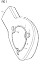
Fig. 1 zeigt einen Abschnitt eines Körperimplantats mit einen in einen Ausschnitt eingesetzten Markerelement. -
Fig. 2 zeigt eine Draufsicht sowie Schnittansichten des inFig. 1 gezeigten Abschnitts eines Körperimplantats. -
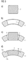
Fig. 3 zeigt wie das Markerelement in den Ausschnitt eingesetzt und dort fixiert wird. -
Fig. 4 zeigt eine Abwandlung des Markerelements vonFig. 3 . -
Fig. 5 zeigt wie ein Markerelement gemäß dem Stand der Technik verpresst wird. - Wie in den
Figuren 1 bis 4 gezeigt ist, hat eine Implantatstruktur 11 eines Körperimplantats bevorzugt eine Bogen- bzw. Kreis- bzw. Ellipsen- bzw. Zylinderform, um an der Wandung eines Körperkanals bzw. Hohlraums flächig anzuliegen. Ein Ausschnitt 1 zum Einsetzen eines Markerelements 2, 2a wird vorzugsweise durch Laserschneiden in der Implantatstruktur 11 geformt. Durch das Laserschneiden sowie die zumindest bereichsweise Bogenform der Implantatstruktur 11 erhält der Ausschnitt 1 zum Einsetzen des Markerelements 2, 2a eine konische Form bzw. eine Kegelform. - In diesen Ausschnitt 1 kann ein Markerelement 2, 2a durch Verpressen bzw. Vernieten so eingesetzt werden, daß ein Formschluß des Markenelements 2, 2a gewährleistet ist. Hierdurch wird eine hohe mechanische Festigkeit bzw. Verriegelung des Markerelements 2 in dem Körperimplantat 1 erzielt. Ein Verkleben, Verschweißen etc. wird hierdurch überflüssig, wodurch die Herstellungskosten des Körperimplantats 1 niedrig gehalten werden können.
- Wie insbesondere in den
Figuren 1 und2 gezeigt ist, wird zum Fixieren des Markerelements 2, 2a der Rand des Ausschnitts 1 mit dem größeren Durchmesser an mehreren Stellen, vorzugsweise an drei Stellen im gleichen Winkelabstand im wesentlichen punktförmig verformt, so dass Material der Implantatstruktur 11 in Richtung zu dem Ausschnitt 1 fließt. Auf diese Weise bildet der verformte Rand 4 zusammen mit der Kegelform des Ausschnitts 1 einen Formschluss mit dem Markerelement 2, 2a, um dieses zu fixieren. - In anderen Worten wird der Rand 4 durch eine Verpressung bereichsweise 3 so verformt, dass der verformte Rand 4a in den Bereich des Ausschnitts 1 fließt, um das eingesetzte Markerelement 2, 2a formschlüssig zu fixieren. Der verformte Rand 4a hat dabei im wesentlichen dieselbe Höhe wie der nicht verformte Rand 4 und es wechseln sich verformte Ränder 4a und nicht verformte Ränder 4 entlang des Umfangs ab.
- Die Verpressung 3 zum Bilden des verformten Rands 4a ist vorzugsweise im wesentlichen punktförmig, d.h. wie eine mittels eines Körners erzeugte Körnung ausgebildet, die mittels Eindrücken oder Einprägen eines im wesentlichen spitzen Gegenstands (Körner) in die Implantatstruktur 11 erzeugt wird. Dabei bildet sich eine im wesentlichen kreisrunde Vertiefung an der Stelle der Verpressung 3 durch das Eindringen des spitzen Gegenstands in das Material der Implantatstruktur 11.
- Die Erfindung ist jedoch nicht auf das Bilden einer kreisrunden Vertiefung beschränkt, sondern die Vertiefung kann auch eine beliebige andere Querschnittsform haben, um die Verpressung 3 zu bilden. Es ist lediglich erforderlich, durch die Verpressung 3 ein Fließen des Materials der Implantatstruktur 11 derart zu erzeugen, dass der Rand 4 des Ausschnitts 1 verformt wird, um durch den verformten Rand 4a einen Formschluss mit dem Markerelement 2, 2a zu bilden.
- Die Verpressung 3 zum Bilden des verformten Rands 4a wird vorzugsweise nur an einer Außenseite 11 a der Implantatstruktur 11 erzeugt, weil das Markerelement 2, 2a durch die Kegelform des Ausschnitts 1 nicht aus der Innenseite 11 b der Implantatstruktur 11 austreten kann. Die Erfindung ist jedoch nicht hierauf beschränkt. Die Verpressung 3 kann auch auf der Innenseite 11b oder auf beiden Seiten, der Innenseite 11 b und der Aussenseite 11a, erzeugt werden.
- Darüber hinaus muss der Ausschnitt 1 keine durchgängige Öffnung bilden, sondern kann als Sackloch bzw. Aushöhlung gebildet sein, so dass das Markerelement 2, 2a auf einer Seite, vorzugsweise der Innenseite des Körperimplantats, durch den Boden der Aushöhlung fixiert wird und auf der anderen Seite durch die Verpressung 3 mit dem verformten Rand 4a.
- Das Markerelement 2 kann vor dem Einsetzen und Verpressen eine zylindrische Form haben, wie in
Fig. 3a gezeigt ist. Durch ein geeignetes Niet- oder Presswerkzeug wird das Markerelement 2 so verpresst, dass es die Gestalt des Ausschnitts 1 annimmt, wie inFig. 3d gezeigt ist. Danach wird das Markerelement 2 durch Bilden der Verpressung 3 und Erzeugen des verformten Rands 4a in dem Ausschnitt 1 gesichert bzw. fixiert. - Das Markerelement 2a kann jedoch bereits vor dem Einsetzen in den Ausschnitt 1 dessen Gestalt aufweisen, wie in
Fig. 4a gezeigt ist. Ein derart gestaltetes Markerelement 2a wird vorzugsweise dadurch hergestellt, dass es aus einem Rohr ausgeschnitten wird. -
Fig. 2 ,3d und4d zeigen schließlich daß verpreßte Markerelement 2, 2a in dem Körperimplantat. Vorzugsweise wird das Markerelement 2 dabei so verpreßt, daß es im wesentlichen mit der Implantatstruktur 11 eine ebene Fläche bildet. Hierdurch werden Kanten an dem Übergang zwischen dem Markerelement 2, 2a und dem Körperimplantat vermieden, die ansonsten zu Verletzungen eines Körperkanals, in den das Körperimplantat eingesetzt wird, führen könnten. - Der Marker 2, 2a weist vorzugsweise ein röntgensichtbares Material, wie beispielsweise Gold, Platin, Tantal, Niob oder eine Platinlegierung, wie beispielsweise Platin-Iridium, auf.
- Vorzugsweise ist das Markerelement 2, 2a in seinen Abmessungen so auf den Ausschnitt 1 abgestimmt, daß das Markerelement 2, 2a nach dem Verpressen im wesentlichen innen/außen eben mit der Implantatstruktur 11 ist. Falls jedoch eine erhöhte Anforderung an die Ebenheit gestellt wird, kann das Markerelement 2, 2a auch etwas größer bemessen sein und nach dem Verpressen eine Oberflächenbehandlung, beispielsweise durch einen Laser, Elektropolieren oder Schleifen, erhalten.
- Durch die Verpressung 3 zum Erzeugen des verformten Rands 4a wird ein Formschluß zwischen dem Markerelement 2, 2a und der Implantatstruktur 11 gebildet, so dass eine gute Befestigung des Markerelements 2, 2a in der Implantatstruktur 11 gewährleistet ist. Ein Verkleben bzw. Verschweißen kann entfallen, um Fertigungskosten einzusparen. Jedoch kann auch zusätzlich zu dem Formschluß ein Verkleben bzw. Verschweißen des Markerelements 2, 2a erfolgen.
- Das Körperimplantat weist bevorzugt eines der folgenden Materialien auf: rostfreier Edelstahl, Kobalt-Chrom-Tantal-Legierung, Polymere, selbstabbaubare Werkstoffe, wie beispielsweise Milchsäure-Werkstoffe bzw. Derivaten, sowie Nitinol (Nickel-Titan-Legierungen) und/oder andere selbstexpandierbare Werkstoffe, wie beispielsweise sogenannte Formgedächtnis-Werkstoffe.
-
- 1
- Ausschnitt
- 2, 2a
- Markerelement
- 3
- Verpressung
- 4
- Rand
- 4a
- verformter Rand
- 11
- Implantatstruktur
- 11a
- Aussenseite
- 11b
- Innenseite
- 14
- Innenkonus
- 16
- Ringspalt
- 18
- Ringspalt
Claims (10)
- Körperimplantat, insbesondere Stent zum Einführen oder Implantieren in einen lebenden Körper, mit einem Markerelement (2; 2a) aus einem röntgensichtbaren Material, das in einen Ausschnitt (1) einer Implantatstruktur (11) eingesetzt ist, dadurch gekennzeichnet, dass zumindest ein Rand (4) des Ausschnitts (1) bereichsweise derart verformt bzw. verpresst ist, dass das Markerelement (2; 2a) formschlüssig von dem Ausschnitt (1) aufgenommen ist, indem sich verformte Ränder (4a) und nicht verformte Ränder (4) entlang des Umfangs des Ausschnitts (1) abwechseln.
- Körperimplantat nach Anspruch 1, wobei der Ausschnitt (1) im wesentlichen konisch ist und der Rand (4) mit dem größeren Durchmesser verpresst ist, um das Markerelement (2; 2a) zu fixieren.
- Körperimplantat nach einem der vorherigen Ansprüche, wobei der Rand (4) an mehreren Stellen im wesentlichen punktförmig verformt ist.
- Körperimplantat nach einem der vorherigen Ansprüche, wobei das Markerelement (2; 2a) vor einem Einpressen im wesentlichen zylindrisch ist und nach dem Einpressen im Querschnitt eine Kreisbogenform in Übereinstimmung mit dem Ausschnitt (1) aufweist oder vor dem Einpressen bereits die Kreisbogenform aufweist.
- Körperimplantat nach einem der vorherigen Ansprüche, wobei das Markerelement (2; 2a) nach dem Einpressen bzw. Einnieten innen/außen im wesentlichen eben mit der Implantatstruktur (11) ist.
- Körperimplantat nach einem der vorherigen Ansprüche, wobei das Markerelement (2; 2a) ein Material mit hoher Absorption für Röntgenstrahlen wie beispielsweise Gold, Platin, Tantal, Platinlegierung, Platin-Iridium, Niob aufweist.
- Verfahren zum Herstellen eines Körperimplantats, insbesondere eines Stents, mit den Schritten:Formen eines Ausschnitts (1) in einer Implantatstruktur (11);Einsetzen eines Markerelements (2; 2a) in den Ausschnitt (1); undgekennzeichnet durch den Schritt:Verformen bzw. Verpressen (3) eines Rands (4) des Ausschnitts (1) bereichsweise derart, dass das Markerelement (2; 2a) formschlüssig von dem Ausschnitt (1) aufgenommen wird, indem sich verformte Ränder (4a) und nicht verformte Ränder (4) entlang des Umfangs des Ausschnitts (1) abwechseln.
- Verfahren nach Anspruch 7, des weiteren mit dem Schritten:Formen des Ausschnitts (1) im wesentlichen in einer konischen Gestalt; undVerpressen des Rands (4) mit dem größeren Durchmesser, um das Markerelement (2; 2a) zu fixieren.
- Verfahren nach Anspruch 7 oder 8, des weiteren mit dem Schritt des punktförmigen Verformens (3) des Rands (4) an mehreren Stellen, vorzugsweise an drei Stellen in im wesentlichen gleichen Winkelabständen.
- Verfahren nach einem der Ansprüche 7 bis 9, des weiteren mit dem Schritt des Ausschneidens des Markerelements (2a) aus einem Rohr.
Applications Claiming Priority (2)
| Application Number | Priority Date | Filing Date | Title |
|---|---|---|---|
| DE102012005356.8A DE102012005356B4 (de) | 2012-03-16 | 2012-03-16 | Körperimplantat mit Markerelement und Verfahren zum Herstellen desselben |
| PCT/EP2012/005093 WO2013135260A1 (de) | 2012-03-16 | 2012-12-10 | Körperimplantat mit markerelement |
Publications (2)
| Publication Number | Publication Date |
|---|---|
| EP2787934A1 EP2787934A1 (de) | 2014-10-15 |
| EP2787934B1 true EP2787934B1 (de) | 2017-07-19 |
Family
ID=47501056
Family Applications (1)
| Application Number | Title | Priority Date | Filing Date |
|---|---|---|---|
| EP12809597.3A Active EP2787934B1 (de) | 2012-03-16 | 2012-12-10 | Körperimplantat mit markerelement |
Country Status (3)
| Country | Link |
|---|---|
| EP (1) | EP2787934B1 (de) |
| DE (1) | DE102012005356B4 (de) |
| WO (1) | WO2013135260A1 (de) |
Families Citing this family (1)
| Publication number | Priority date | Publication date | Assignee | Title |
|---|---|---|---|---|
| DE102013020689B3 (de) * | 2013-12-04 | 2015-02-19 | Admedes Schuessler Gmbh | Körperimplantat und Verfahren zum Herstellen desselben sowie Verfahren zum Verbessern der Röntgensichtbarkeit |
Family Cites Families (7)
| Publication number | Priority date | Publication date | Assignee | Title |
|---|---|---|---|---|
| IL117472A0 (en) * | 1996-03-13 | 1996-07-23 | Instent Israel Ltd | Radiopaque stent markers |
| US20060222756A1 (en) * | 2000-09-29 | 2006-10-05 | Cordis Corporation | Medical devices, drug coatings and methods of maintaining the drug coatings thereon |
| DE10325678A1 (de) * | 2003-06-02 | 2004-12-23 | Biotronik Meß- und Therapiegeräte GmbH & Co. Ingenieurbüro Berlin | Verbindungssystem zur Verbindung eines Stents mit einem radioopaken Marker sowie Verfahren zur Herstellung einer Verbindung zwischen einem Stent und zwei oder mehreren radioopaken Markern |
| DE102005019612B4 (de) * | 2005-04-27 | 2010-11-25 | Admedes Schuessler Gmbh | Mechanische Verriegelung eines Röntgenmarkers im Eyelet eines Stents oder in einem anderen Körperimplantat |
| US20070156230A1 (en) * | 2006-01-04 | 2007-07-05 | Dugan Stephen R | Stents with radiopaque markers |
| US20070266542A1 (en) * | 2006-05-08 | 2007-11-22 | Cook Incorporated | Radiopaque marker for intraluminal medical device |
| GB0624419D0 (en) * | 2006-12-06 | 2007-01-17 | Angiomed Ag | Stenting ring with marker |
-
2012
- 2012-03-16 DE DE102012005356.8A patent/DE102012005356B4/de not_active Expired - Fee Related
- 2012-12-10 WO PCT/EP2012/005093 patent/WO2013135260A1/de not_active Ceased
- 2012-12-10 EP EP12809597.3A patent/EP2787934B1/de active Active
Also Published As
| Publication number | Publication date |
|---|---|
| EP2787934A1 (de) | 2014-10-15 |
| DE102012005356B4 (de) | 2016-05-19 |
| WO2013135260A1 (de) | 2013-09-19 |
| DE102012005356A1 (de) | 2013-09-19 |
Similar Documents
| Publication | Publication Date | Title |
|---|---|---|
| DE60319765T2 (de) | Intraluminale medizinische Vorrichtung mit radiopaken Markern | |
| DE69738023T2 (de) | Intravaskulärer stent | |
| DE60207692T2 (de) | Röntgenopakes intraluminales medizinisches gerät | |
| DE60021040T2 (de) | Flexibler medizinischer Stent | |
| DE602004010347T2 (de) | Stent mit unabhängigen, bei der Aufweitung entkuppelbaren Segmenten | |
| DE602004009994T2 (de) | Stent mit einem angefügten Marker in der Form einer Hülse | |
| DE69630030T2 (de) | Endovaskularer stent | |
| DE69924400T3 (de) | Endoluminales gewebe mit kontinuierlich kurvenlinearen drahtformen | |
| DE102005039136B4 (de) | Verbesserung der Röntgensichtbarkeit und Korrosionsbeständigkeit von NiTi Stents unter Einsatz von Nieten aus Sandwichmaterial | |
| EP3165238B1 (de) | Röntgenmarker für eine endoprothese | |
| DE19951279A1 (de) | Ballonexpandierbarer bedeckter Stent | |
| DE102014113836B4 (de) | Verfahren zum Herstellen eines patientenspezifischen, endovaskulären Implantats | |
| DE102010008360A1 (de) | Medizinisches Implantat, in welchem beim Crimpen bzw. Falten Lücken verbleiben, Verfahren und Einrichtung zum Verbringen | |
| EP2422748A2 (de) | Medizinisches Implantat, insbesondere Klappenimplantat, zur Implantation in einen tierischen und/oder menschlichen Körper sowie Verfahren, insbesondere Herstellungsverfahren, zur Herstellung einer Implantationsvorrichtung für das medizinische Implantat | |
| EP3678589B1 (de) | Intraluminales gefässprothesensystem | |
| DE102005019612B4 (de) | Mechanische Verriegelung eines Röntgenmarkers im Eyelet eines Stents oder in einem anderen Körperimplantat | |
| DE102011054172A1 (de) | Transkatheter-Klappenprothese | |
| DE102004045994A1 (de) | Stent zur Implantation in oder um ein Hohlorgan mit Markerelementen aus einem röntgenopaken Material | |
| EP1628594A1 (de) | Verbindungssystem zur verbindung eines stents mit einem radioopaken marker sowie verfahren zur herstellung einer verbindung zwischen einem stent und zwei oder mehreren radioopaken markern | |
| DE602004011897T2 (de) | Stent-Transplantat mit Elutionsöffnungen | |
| DE102004054084B4 (de) | Stent mit einem Marker zur Verbesserung der Röntgensichtbarkeit, die Verwendung sowie ein Verfahren zum Herstellen eines derartigen Stents | |
| DE202004014789U1 (de) | Stent zur Implantation in oder um ein Hohlorgan mit Markerelementen aus einem röntgenopaken Material | |
| DE102012005356B4 (de) | Körperimplantat mit Markerelement und Verfahren zum Herstellen desselben | |
| DE102011115238B4 (de) | Körperimplantat mit verbesserter Röntgensichtbarkeit, Kombination aus einem Katheter, einem Führungsdraht und einem Körperimplantat und Verfahren zum Erhöhen der Röntgensichtbarkeit eines Körperimplantats | |
| DE69924260T2 (de) | Expandierbarer stent für kleinlumige gefässe |
Legal Events
| Date | Code | Title | Description |
|---|---|---|---|
| PUAI | Public reference made under article 153(3) epc to a published international application that has entered the european phase |
Free format text: ORIGINAL CODE: 0009012 |
|
| 17P | Request for examination filed |
Effective date: 20140710 |
|
| AK | Designated contracting states |
Kind code of ref document: A1 Designated state(s): AL AT BE BG CH CY CZ DE DK EE ES FI FR GB GR HR HU IE IS IT LI LT LU LV MC MK MT NL NO PL PT RO RS SE SI SK SM TR |
|
| DAX | Request for extension of the european patent (deleted) | ||
| 17Q | First examination report despatched |
Effective date: 20160209 |
|
| GRAP | Despatch of communication of intention to grant a patent |
Free format text: ORIGINAL CODE: EPIDOSNIGR1 |
|
| INTG | Intention to grant announced |
Effective date: 20170213 |
|
| GRAS | Grant fee paid |
Free format text: ORIGINAL CODE: EPIDOSNIGR3 |
|
| GRAA | (expected) grant |
Free format text: ORIGINAL CODE: 0009210 |
|
| AK | Designated contracting states |
Kind code of ref document: B1 Designated state(s): AL AT BE BG CH CY CZ DE DK EE ES FI FR GB GR HR HU IE IS IT LI LT LU LV MC MK MT NL NO PL PT RO RS SE SI SK SM TR |
|
| REG | Reference to a national code |
Ref country code: GB Ref legal event code: FG4D Free format text: NOT ENGLISH |
|
| REG | Reference to a national code |
Ref country code: CH Ref legal event code: EP |
|
| REG | Reference to a national code |
Ref country code: IE Ref legal event code: FG4D Free format text: LANGUAGE OF EP DOCUMENT: GERMAN |
|
| REG | Reference to a national code |
Ref country code: AT Ref legal event code: REF Ref document number: 909649 Country of ref document: AT Kind code of ref document: T Effective date: 20170815 |
|
| REG | Reference to a national code |
Ref country code: DE Ref legal event code: R096 Ref document number: 502012010831 Country of ref document: DE |
|
| REG | Reference to a national code |
Ref country code: NL Ref legal event code: MP Effective date: 20170719 |
|
| REG | Reference to a national code |
Ref country code: LT Ref legal event code: MG4D |
|
| PG25 | Lapsed in a contracting state [announced via postgrant information from national office to epo] |
Ref country code: NO Free format text: LAPSE BECAUSE OF FAILURE TO SUBMIT A TRANSLATION OF THE DESCRIPTION OR TO PAY THE FEE WITHIN THE PRESCRIBED TIME-LIMIT Effective date: 20171019 Ref country code: LT Free format text: LAPSE BECAUSE OF FAILURE TO SUBMIT A TRANSLATION OF THE DESCRIPTION OR TO PAY THE FEE WITHIN THE PRESCRIBED TIME-LIMIT Effective date: 20170719 Ref country code: SE Free format text: LAPSE BECAUSE OF FAILURE TO SUBMIT A TRANSLATION OF THE DESCRIPTION OR TO PAY THE FEE WITHIN THE PRESCRIBED TIME-LIMIT Effective date: 20170719 Ref country code: HR Free format text: LAPSE BECAUSE OF FAILURE TO SUBMIT A TRANSLATION OF THE DESCRIPTION OR TO PAY THE FEE WITHIN THE PRESCRIBED TIME-LIMIT Effective date: 20170719 Ref country code: FI Free format text: LAPSE BECAUSE OF FAILURE TO SUBMIT A TRANSLATION OF THE DESCRIPTION OR TO PAY THE FEE WITHIN THE PRESCRIBED TIME-LIMIT Effective date: 20170719 Ref country code: NL Free format text: LAPSE BECAUSE OF FAILURE TO SUBMIT A TRANSLATION OF THE DESCRIPTION OR TO PAY THE FEE WITHIN THE PRESCRIBED TIME-LIMIT Effective date: 20170719 |
|
| PG25 | Lapsed in a contracting state [announced via postgrant information from national office to epo] |
Ref country code: ES Free format text: LAPSE BECAUSE OF FAILURE TO SUBMIT A TRANSLATION OF THE DESCRIPTION OR TO PAY THE FEE WITHIN THE PRESCRIBED TIME-LIMIT Effective date: 20170719 Ref country code: RS Free format text: LAPSE BECAUSE OF FAILURE TO SUBMIT A TRANSLATION OF THE DESCRIPTION OR TO PAY THE FEE WITHIN THE PRESCRIBED TIME-LIMIT Effective date: 20170719 Ref country code: BG Free format text: LAPSE BECAUSE OF FAILURE TO SUBMIT A TRANSLATION OF THE DESCRIPTION OR TO PAY THE FEE WITHIN THE PRESCRIBED TIME-LIMIT Effective date: 20171019 Ref country code: GR Free format text: LAPSE BECAUSE OF FAILURE TO SUBMIT A TRANSLATION OF THE DESCRIPTION OR TO PAY THE FEE WITHIN THE PRESCRIBED TIME-LIMIT Effective date: 20171020 Ref country code: IS Free format text: LAPSE BECAUSE OF FAILURE TO SUBMIT A TRANSLATION OF THE DESCRIPTION OR TO PAY THE FEE WITHIN THE PRESCRIBED TIME-LIMIT Effective date: 20171119 Ref country code: PL Free format text: LAPSE BECAUSE OF FAILURE TO SUBMIT A TRANSLATION OF THE DESCRIPTION OR TO PAY THE FEE WITHIN THE PRESCRIBED TIME-LIMIT Effective date: 20170719 Ref country code: LV Free format text: LAPSE BECAUSE OF FAILURE TO SUBMIT A TRANSLATION OF THE DESCRIPTION OR TO PAY THE FEE WITHIN THE PRESCRIBED TIME-LIMIT Effective date: 20170719 |
|
| REG | Reference to a national code |
Ref country code: DE Ref legal event code: R097 Ref document number: 502012010831 Country of ref document: DE |
|
| PG25 | Lapsed in a contracting state [announced via postgrant information from national office to epo] |
Ref country code: CZ Free format text: LAPSE BECAUSE OF FAILURE TO SUBMIT A TRANSLATION OF THE DESCRIPTION OR TO PAY THE FEE WITHIN THE PRESCRIBED TIME-LIMIT Effective date: 20170719 Ref country code: RO Free format text: LAPSE BECAUSE OF FAILURE TO SUBMIT A TRANSLATION OF THE DESCRIPTION OR TO PAY THE FEE WITHIN THE PRESCRIBED TIME-LIMIT Effective date: 20170719 Ref country code: DK Free format text: LAPSE BECAUSE OF FAILURE TO SUBMIT A TRANSLATION OF THE DESCRIPTION OR TO PAY THE FEE WITHIN THE PRESCRIBED TIME-LIMIT Effective date: 20170719 |
|
| PLBE | No opposition filed within time limit |
Free format text: ORIGINAL CODE: 0009261 |
|
| STAA | Information on the status of an ep patent application or granted ep patent |
Free format text: STATUS: NO OPPOSITION FILED WITHIN TIME LIMIT |
|
| PG25 | Lapsed in a contracting state [announced via postgrant information from national office to epo] |
Ref country code: SM Free format text: LAPSE BECAUSE OF FAILURE TO SUBMIT A TRANSLATION OF THE DESCRIPTION OR TO PAY THE FEE WITHIN THE PRESCRIBED TIME-LIMIT Effective date: 20170719 Ref country code: SK Free format text: LAPSE BECAUSE OF FAILURE TO SUBMIT A TRANSLATION OF THE DESCRIPTION OR TO PAY THE FEE WITHIN THE PRESCRIBED TIME-LIMIT Effective date: 20170719 Ref country code: EE Free format text: LAPSE BECAUSE OF FAILURE TO SUBMIT A TRANSLATION OF THE DESCRIPTION OR TO PAY THE FEE WITHIN THE PRESCRIBED TIME-LIMIT Effective date: 20170719 Ref country code: IT Free format text: LAPSE BECAUSE OF FAILURE TO SUBMIT A TRANSLATION OF THE DESCRIPTION OR TO PAY THE FEE WITHIN THE PRESCRIBED TIME-LIMIT Effective date: 20170719 |
|
| 26N | No opposition filed |
Effective date: 20180420 |
|
| REG | Reference to a national code |
Ref country code: CH Ref legal event code: PL |
|
| GBPC | Gb: european patent ceased through non-payment of renewal fee |
Effective date: 20171210 |
|
| PG25 | Lapsed in a contracting state [announced via postgrant information from national office to epo] |
Ref country code: SI Free format text: LAPSE BECAUSE OF FAILURE TO SUBMIT A TRANSLATION OF THE DESCRIPTION OR TO PAY THE FEE WITHIN THE PRESCRIBED TIME-LIMIT Effective date: 20170719 |
|
| REG | Reference to a national code |
Ref country code: IE Ref legal event code: MM4A |
|
| PG25 | Lapsed in a contracting state [announced via postgrant information from national office to epo] |
Ref country code: MT Free format text: LAPSE BECAUSE OF FAILURE TO SUBMIT A TRANSLATION OF THE DESCRIPTION OR TO PAY THE FEE WITHIN THE PRESCRIBED TIME-LIMIT Effective date: 20170719 Ref country code: LU Free format text: LAPSE BECAUSE OF NON-PAYMENT OF DUE FEES Effective date: 20171210 |
|
| REG | Reference to a national code |
Ref country code: FR Ref legal event code: ST Effective date: 20180831 |
|
| REG | Reference to a national code |
Ref country code: BE Ref legal event code: MM Effective date: 20171231 |
|
| PG25 | Lapsed in a contracting state [announced via postgrant information from national office to epo] |
Ref country code: FR Free format text: LAPSE BECAUSE OF NON-PAYMENT OF DUE FEES Effective date: 20180102 Ref country code: IE Free format text: LAPSE BECAUSE OF NON-PAYMENT OF DUE FEES Effective date: 20171210 |
|
| PG25 | Lapsed in a contracting state [announced via postgrant information from national office to epo] |
Ref country code: CH Free format text: LAPSE BECAUSE OF NON-PAYMENT OF DUE FEES Effective date: 20171231 Ref country code: LI Free format text: LAPSE BECAUSE OF NON-PAYMENT OF DUE FEES Effective date: 20171231 Ref country code: GB Free format text: LAPSE BECAUSE OF NON-PAYMENT OF DUE FEES Effective date: 20171210 Ref country code: BE Free format text: LAPSE BECAUSE OF NON-PAYMENT OF DUE FEES Effective date: 20171231 |
|
| REG | Reference to a national code |
Ref country code: AT Ref legal event code: MM01 Ref document number: 909649 Country of ref document: AT Kind code of ref document: T Effective date: 20171210 |
|
| PG25 | Lapsed in a contracting state [announced via postgrant information from national office to epo] |
Ref country code: AT Free format text: LAPSE BECAUSE OF NON-PAYMENT OF DUE FEES Effective date: 20171210 |
|
| PG25 | Lapsed in a contracting state [announced via postgrant information from national office to epo] |
Ref country code: MC Free format text: LAPSE BECAUSE OF FAILURE TO SUBMIT A TRANSLATION OF THE DESCRIPTION OR TO PAY THE FEE WITHIN THE PRESCRIBED TIME-LIMIT Effective date: 20170719 Ref country code: HU Free format text: LAPSE BECAUSE OF FAILURE TO SUBMIT A TRANSLATION OF THE DESCRIPTION OR TO PAY THE FEE WITHIN THE PRESCRIBED TIME-LIMIT; INVALID AB INITIO Effective date: 20121210 |
|
| PG25 | Lapsed in a contracting state [announced via postgrant information from national office to epo] |
Ref country code: CY Free format text: LAPSE BECAUSE OF FAILURE TO SUBMIT A TRANSLATION OF THE DESCRIPTION OR TO PAY THE FEE WITHIN THE PRESCRIBED TIME-LIMIT Effective date: 20170719 |
|
| PG25 | Lapsed in a contracting state [announced via postgrant information from national office to epo] |
Ref country code: MK Free format text: LAPSE BECAUSE OF FAILURE TO SUBMIT A TRANSLATION OF THE DESCRIPTION OR TO PAY THE FEE WITHIN THE PRESCRIBED TIME-LIMIT Effective date: 20170719 |
|
| PG25 | Lapsed in a contracting state [announced via postgrant information from national office to epo] |
Ref country code: TR Free format text: LAPSE BECAUSE OF FAILURE TO SUBMIT A TRANSLATION OF THE DESCRIPTION OR TO PAY THE FEE WITHIN THE PRESCRIBED TIME-LIMIT Effective date: 20170719 |
|
| PG25 | Lapsed in a contracting state [announced via postgrant information from national office to epo] |
Ref country code: PT Free format text: LAPSE BECAUSE OF FAILURE TO SUBMIT A TRANSLATION OF THE DESCRIPTION OR TO PAY THE FEE WITHIN THE PRESCRIBED TIME-LIMIT Effective date: 20170719 |
|
| PG25 | Lapsed in a contracting state [announced via postgrant information from national office to epo] |
Ref country code: AL Free format text: LAPSE BECAUSE OF FAILURE TO SUBMIT A TRANSLATION OF THE DESCRIPTION OR TO PAY THE FEE WITHIN THE PRESCRIBED TIME-LIMIT Effective date: 20170719 |
|
| PGFP | Annual fee paid to national office [announced via postgrant information from national office to epo] |
Ref country code: DE Payment date: 20251223 Year of fee payment: 14 |