EP2786665B1 - Schutzelement, das zwei Teile umfasst, die über eine Gelenkverbindung miteinander verbunden sind - Google Patents
Schutzelement, das zwei Teile umfasst, die über eine Gelenkverbindung miteinander verbunden sind Download PDFInfo
- Publication number
- EP2786665B1 EP2786665B1 EP14162942.8A EP14162942A EP2786665B1 EP 2786665 B1 EP2786665 B1 EP 2786665B1 EP 14162942 A EP14162942 A EP 14162942A EP 2786665 B1 EP2786665 B1 EP 2786665B1
- Authority
- EP
- European Patent Office
- Prior art keywords
- strap
- protective element
- user
- face
- outer face
- Prior art date
- Legal status (The legal status is an assumption and is not a legal conclusion. Google has not performed a legal analysis and makes no representation as to the accuracy of the status listed.)
- Not-in-force
Links
- 230000001681 protective effect Effects 0.000 title claims description 32
- 239000004753 textile Substances 0.000 claims description 14
- 238000005304 joining Methods 0.000 claims description 5
- 239000000463 material Substances 0.000 description 9
- 230000035939 shock Effects 0.000 description 7
- 230000002441 reversible effect Effects 0.000 description 6
- 238000010521 absorption reaction Methods 0.000 description 4
- 239000004744 fabric Substances 0.000 description 4
- 239000006260 foam Substances 0.000 description 2
- 238000009423 ventilation Methods 0.000 description 2
- 238000005520 cutting process Methods 0.000 description 1
- 238000009826 distribution Methods 0.000 description 1
- 230000000694 effects Effects 0.000 description 1
- 229920001971 elastomer Polymers 0.000 description 1
- 239000000806 elastomer Substances 0.000 description 1
- 239000013536 elastomeric material Substances 0.000 description 1
- 238000002347 injection Methods 0.000 description 1
- 239000007924 injection Substances 0.000 description 1
- 238000004519 manufacturing process Methods 0.000 description 1
- 238000000465 moulding Methods 0.000 description 1
- 229920000515 polycarbonate Polymers 0.000 description 1
- 239000004417 polycarbonate Substances 0.000 description 1
- 229920000642 polymer Polymers 0.000 description 1
- 238000000926 separation method Methods 0.000 description 1
- 210000004243 sweat Anatomy 0.000 description 1
Images


Classifications
-
- A—HUMAN NECESSITIES
- A41—WEARING APPAREL
- A41D—OUTERWEAR; PROTECTIVE GARMENTS; ACCESSORIES
- A41D13/00—Professional, industrial or sporting protective garments, e.g. surgeons' gowns or garments protecting against blows or punches
- A41D13/015—Professional, industrial or sporting protective garments, e.g. surgeons' gowns or garments protecting against blows or punches with shock-absorbing means
- A41D13/0153—Professional, industrial or sporting protective garments, e.g. surgeons' gowns or garments protecting against blows or punches with shock-absorbing means having hinged or separable parts
-
- A—HUMAN NECESSITIES
- A41—WEARING APPAREL
- A41D—OUTERWEAR; PROTECTIVE GARMENTS; ACCESSORIES
- A41D13/00—Professional, industrial or sporting protective garments, e.g. surgeons' gowns or garments protecting against blows or punches
- A41D13/05—Professional, industrial or sporting protective garments, e.g. surgeons' gowns or garments protecting against blows or punches protecting only a particular body part
- A41D13/0512—Neck or shoulders area
-
- A—HUMAN NECESSITIES
- A41—WEARING APPAREL
- A41D—OUTERWEAR; PROTECTIVE GARMENTS; ACCESSORIES
- A41D13/00—Professional, industrial or sporting protective garments, e.g. surgeons' gowns or garments protecting against blows or punches
- A41D13/05—Professional, industrial or sporting protective garments, e.g. surgeons' gowns or garments protecting against blows or punches protecting only a particular body part
- A41D13/055—Protector fastening, e.g. on the human body
- A41D13/0556—Protector fastening, e.g. on the human body with releasable fastening means
- A41D13/0568—Protector fastening, e.g. on the human body with releasable fastening means with straps
-
- A—HUMAN NECESSITIES
- A63—SPORTS; GAMES; AMUSEMENTS
- A63B—APPARATUS FOR PHYSICAL TRAINING, GYMNASTICS, SWIMMING, CLIMBING, OR FENCING; BALL GAMES; TRAINING EQUIPMENT
- A63B71/00—Games or sports accessories not covered in groups A63B1/00 - A63B69/00
- A63B71/08—Body-protectors for players or sportsmen, i.e. body-protecting accessories affording protection of body parts against blows or collisions
- A63B71/12—Body-protectors for players or sportsmen, i.e. body-protecting accessories affording protection of body parts against blows or collisions for the body or the legs, e.g. for the shoulders
- A63B2071/1208—Body-protectors for players or sportsmen, i.e. body-protecting accessories affording protection of body parts against blows or collisions for the body or the legs, e.g. for the shoulders for the breast and the abdomen, e.g. breast plates
Definitions
- the present invention relates to a protection element of at least a part of the body of a user, of the type comprising a first part intended to cover at least part of a user's joint, and a second part intended to cover at least a part of the user's a part of a member of the user articulated to said articulation.
- Such protective equipment forms for example a shoulder-arm protection intended for law enforcement or security officers.
- Such equipment must be able to protect the user against violent shocks, possibly carried by heavy objects blunt or not.
- each part is generally formed of a rigid shell lined with an elastically deformable mattress pressed against the rigid shell and forming a padding.
- the mattress is formed by a foam-wrapped fabric arranged to crash in case of shock to absorb energy and thus protect the user's member against which the mattress is applied.
- the rigid shell receives the shock, absorbs some of its energy and protects the user by preventing the source of shock to reach directly the member carrying the equipment, while the mattress is arranged to crash between the hull and the limb to absorb another part of the energy.
- the first and second parts generally comprise a shell specific to each part, and a common mattress to both parts.
- the fact of having separate shells between the first and second parts makes it possible to give a certain flexibility to the protective equipment, and a certain freedom of movement to the articulation.
- US2005246812 discloses a protection element with several parts.
- An object of the invention is to improve the accompaniment of the movements of the user by the protective equipment.
- the invention characterized by the claims, relates to a protective equipment of the aforementioned type, wherein the first and second parts are hinged to each other by a connection joint having a degree of freedom in translation along a main direction joining a center of the first portion to a center of the second portion.
- the term "outer” is defined by what is turned outwardly of the protective vest, that is to say the opposite of the part of the body carrying the equipment, and the term “ internal “by what is turned inward of the equipment, that is to say towards the part of the body carrying the equipment.
- the protective vest 10 shown on the Figure 1 is of the type bumpers for law enforcement or for security officers or other. It comprises a main portion 12, intended to cover a trunk of the user, and two side portions 14, each intended to cover a shoulder and at least a portion of the user's arm.
- the main part 12 comprises a front part 20, intended to cover a front face of the trunk of the user, and a dorsal part 22 ( Figure 2 ), intended to cover the back of the user, the front 20 and dorsal 22 parts being connected to each other by shoulder straps 24.
- the front portions 20, dorsal 22 and the straps 24 are for example linked together by stitching.
- Each of the front and back portions 22 comprises one or more protective panels, each panel being provided with at least one mattress (not shown) of elastically compressible material, for example a foam or an elastomeric material, for example obtained by injection, molding or cutting.
- a plate 25 of rigid material is disposed in front of the mattress, towards the outside of the vest 10.
- the plate 25 can be substantially flat or be shaped to fit the shape of the part of the body it covers, to be ergonomic and thus improve the comfort of the panel while facilitating the freedom of movement of the user.
- Such a plate 25 allows a good distribution of energy when an impact is applied to it, as well as the absorption of a portion of this energy, the absorption then being made by the mattress.
- the mattress and the plate 25 are, for example, coated with a fabric suitable for the field of protective equipment. The production of such panels is known per se and will not be described in more detail here.
- Each protective panel because of its structure, is able to absorb at least a portion of the energy due to impact, including shocks due to blows carried by a third with bare hands or with an object or projectiles launched by a third party, in order to protect the user wearing the equipment, while allowing him to move freely.
- each panel is optionally doubled by one or more textile materials adapted for the absorption and / or evacuation of the sweat of the user, as well as for the ventilation of the vest 10, to enhance the comfort of the user.
- a textile material is for example a so-called "breathable" textile material.
- the front portion 20 further comprises two first lateral flaps 26 at the user's ribs, and the dorsal portion 22 comprises two second lateral flaps 28 at the user's ribs. Said flaps 26, 28 are provided with means for adjusting the tightening of the main part 12 on the trunk of the user.
- These adjustment means comprise primary attachment means (not shown), provided on an outer face of each first flap 26, and secondary attachment means (not shown), provided on an inner face of each second flap 28, and adapted to cooperate with the primary attachment means for the reversible attachment of each second flap 28 to a first flap 26.
- These primary and secondary gripping means are for example self-gripping tape type.
- the straps 24 are two in number, each being provided to cover a shoulder of the user. They delimit between them an upper passage 30 for a neck of the user.
- the vest 10 comprises an opening formed on each side of the vest 10 and defined vertically by a shoulder strap 24 on the one hand and a lateral flap 26, 28 on the other hand, and defined horizontally by the front portion 20 on the one hand and the dorsal part 22 on the other hand, as shown on the Figure 2 , for the passage of an arm of the user.
- each side portion 14 extends above one of the side passages 32.
- Each side portion 14 includes a first portion 34, intended to cover one shoulder of the user, and a second portion 36, intended to cover a portion of the arm of the user who is articulated to said shoulder.
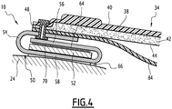
- Each of the first and second parts 34, 36 essentially comprises, from the outside towards the inside, a shell 38, defining an external face 40 of said portion 34, 36, and a mattress 42, defining an internal face 44 ( Figure 4 ) of said portion 34, 36.
- the shell 38 is made of a rigid material, such as polycarbonate for example. It is made in one piece.
- the shell 38 has the general shape of the portion of the member to be protected.
- the outer face of each shell 38 is shaped in a known manner for shock absorption during clashes.
- the conformation is adapted to the part of the body intended to be protected and comprises, for example, protuberances extending on either side of the recesses intended to improve the behavior of the shells 38 in the event of an impact. Since the external form of the protective equipment is not the subject of the invention, it will not be described further here.
- the shell 38 defines a cavity (not shown) facing inward and adapted to receive a member intended to carry the equipment.
- the mattress 42 is disposed in said cavity.
- the mattress 42 covers substantially all of an inner face (not shown) of the shell 38, and thus forms a "lining" of the shell 38.
- the mattress 42 is adapted to absorb shocks.
- the mattress 42 is for example made of an elastically compressible material, of the elastomer type.
- the mattress 42 is made of foam surrounded by fabric.
- Each of the first and second parts 34, 36 has a proximal end 46, close to the other part, respectively 36, 34, and a distal end 48, remote from the other part, respectively 36, 34.
- the first part 34 in particular its distal end 48, partly covers a strap 24 of the main part 12.
- the first portion 34 also covers a portion of the outer face 40 of the second portion 36.
- the proximal end 46 of the first portion 34 covers the proximal end 46 of the second portion 36.
- the second portion 36 is provided with a member 49 for clamping the arm of the user.
- This clamping member 49 is preferably, as shown, closer the distal end 48 as the proximal end 46.
- the clamping member 49 is, in the example shown, a strap.
- Each lateral portion 14 is detachably fastened to a shoulder strap 24 of the main portion 12.
- the protective vest 10 comprises, for each lateral portion 14, a reversible fastening system of said lateral portion 14 to its respective strap 24.
- this reversible system comprises an appendage 50, integral with the first portion 34 of the lateral portion 14, and a fastening strap 52, integral at each of its ends with the respective shoulder strap 24, in particular with an external face of the shoulder strap 24.
- Appendix 50 is typically made of fabric. It is attached, for example stitched and / or riveted, to the distal end 48 of the first portion 34. It has a proximal end 54 of connection to the first portion 34, and a distal end 56 free. It comprises an intermediate portion 58 between its proximal ends 54 and distal 56.
- Appendix 50 has a first large face 60 extending the outer face 40 of the first portion 34, and a second large face 62 ( Figure 6 ), opposite the first large face 60 and extending the inner face 44 of the first portion 34.
- the distal end 56 carries a first attachment member 62. More particularly, the first attachment member 64 is carried by the second major face 62 of the appendix 50.
- the fastening strap 52 is oriented substantially parallel to the shoulder strap 24. It defines with the shoulder strap 24 a passage 66 for the appendix 50.
- the fixing strap 52 has a free face 68 opposite to the passage 64.
- This free face 68 carries a second fastener 70 adapted to cooperate with the first fastener 64 for the reversible joining of the first and second fasteners 64, 70 to each other.
- the first and second fasteners 64, 70 are preferably adapted to be detached from each other by exerting a force of separation on these two members 64, 70, said separating force being oriented substantially perpendicular to a contact interface of said members 64, 70.
- the first and second fasteners 64, 70 are for example of the self-gripping tape type, which allows a quick attachment and does not require a high accuracy in the placement of fasteners relative to one another. Alternatively, they are of the type snap.
- the intermediate portion 58 of the appendix 50 is engaged in the passage 66, and the distal end 56 is folded over the fastening strap 52 so as to cover its free face 68, the second large face 62 of the appendix 50 being oriented towards said free face 68.
- the distal end 56 is folded toward the proximal end 54, and the first and second fasteners 64, 70 cooperate with each other.
- first portion 34 of the lateral portion 14 is also folded so as to cover the fastening strap 52, the inner face of said first portion 34 being oriented towards the attachment strap 52.
- the attachment strap 52 is thus found again. interposed between the shoulder strap 24 and the first portion 34.
- intermediate portion 58 and the distal end 56 of the appendix 50 are each folded towards the first portion 34.
- Each lateral portion 14 is thus firmly attached to the main portion 12. Indeed, in case of attempted tearing of one of the side portions 14 by a third person, the main pulling efforts are taken care of by the strap 52. Only a residual portion of the pulling forces is taken up by the fasteners 64, 70, and this residual part is oriented parallel to the contact interface of the first and second fasteners 64, 70, which is not suitable for detaching the fasteners 64, 70 from each other. Accordingly, to separate the side portion 14 of the main portion 12 while the vest 10 is worn by the user, the third person should tear the strap 52 of the main portion 12, which requires a much greater effort than that normally necessary to separate the fasteners 64, 70.
- Each side portion 14 can, however, be easily detached from the main part 12 when its user no longer wears the vest 10. It is sufficient to raise the first portion 34 to release access to the distal end 56 of the appendix 50 , then to seize this distal end 56 by exerting a force directed away from the shoulder strap 24 to separate the first and second fasteners 64, 70. It then remains only to release the appendix 50 of the passage 66 by sliding the distal end 56 to finish separating the lateral portion 14 of the main portion 12.
- each side portion 14 It is also easy and particularly fast to attach each side portion 14 to the main portion 12, performing the preceding operations in reverse order. This makes it possible to choose whether or not to put the lateral parts on the vest, according to the type of situation that the user is confronted with. In addition, the user can easily and quickly add the side parts "on the ground", if the situation requires it.
- This removable attachment also makes it possible to adapt the lateral part 14 to the situation encountered, by choosing more or less rigid shells depending on this situation, for example, or by providing a longer or shorter lateral part 14.
- Each lateral portion 14 also includes, with reference to the Figure 5 , an articular connection 80 for the articulation of the first and second parts 34, 36 to one another.
- This articular connection 80 has three degrees of freedom in rotation; in other words, it is adapted to allow rotation of the second portion 36 relative to the first portion 34 about each axis of the space.
- the articular connection 80 thus has a degree of freedom in rotation around an axis (not shown) substantially perpendicular to the outer face 40 of the second portion 36.
- the articular connection 80 furthermore has a degree of freedom in translation along a main direction P ( Figure 3 ) joining a center C 1 ( Figure 3 ) of the first part 34 has a center C 2 ( Figure 3 ) of the second part 36, and an additional degree of freedom in translation along a secondary direction S ( Figure 3 ) substantially perpendicular to the main direction P, and substantially parallel to the outer face 40 of the second portion 36.
- the main direction P depends on the relative position of the first and second parts 34, 36.
- the articular connection 80 comprises a first strap 84, secured at each of its ends to the first portion 34, and a second strap 86, secured at each of its ends to the second portion 36. Said strips 84, 86 are interwoven with one another. with the other.
- the first strap 84 defines with the first portion 34 a first passage 90 for the second strap 86
- the second strap 86 defines with the second portion 36 a second passage 92 for the first strap 84
- the first strap 84 is engaged in the second passage 92 while the second strap 86 is engaged in the first passage 90.
- Each strap 84, 86 is formed of a semi-rigid material, such as an injected or cut polymer, or a woven material.
- the first strap 84 is fixed to the inner face 44 of the first portion 34. It is rectilinear, and is oriented substantially parallel to a first direction J 1 of junction of the proximal and distal ends 46, 48 of the first portion 34. In particular, the first strap 84 extends from the proximal end 46 to the distal end 48 of the first portion 34.
- the second strap 86 is fixed to the outer face 40 of the second portion 36. It forms an arc.
- This arc is symmetrical with respect to a plane substantially perpendicular to the external face 40 of the second portion and parallel to a second direction J 2 joining the proximal and distal ends 46, 48 of the second portion 36.
- the second strap 86 is oriented substantially perpendicular to said second junction direction J 2 , and is arcuate about an axis (not shown) substantially perpendicular to the outer face 40 of the second portion 36.
- the apex 94 of said arc is closer to the proximal end 46 than the ends 96 of the strap 86.
- the distance from the proximal end 46 to said apex 94 is less than one tenth of the distance from the proximal end. 46 at the distal end 48.
- the first and second parts 34, 36 can slide one above the other.
- the second part 36 follows the movement of the arm of the user and retracts under the first part 34. This prevents that, under the effect of the reduction of the distance from the center C 1 from the first part 34 to the center C 2 of the second part 36 following the lifting of the arm of the user, the lateral part 14 does not come off the arm, releasing a passage between the arm and the lateral part 14.
- the articular connection 80 is of very simple design, and can be manufactured simply and at low cost. It offers great freedom of movement to the user by allowing in particular the twisting movements, which is not the case of equipment in which the parts are articulated together around a single axis.
- each lateral portion 14 further comprises a flexible textile piece 100 connecting the first part 34 to the second part 36.
- This textile piece 100 is fixed, in particular sewn, at a first end, to the distal end 48 of the first part. 34 and, at a second end, at the proximal end 46 of the second portion 36.
- the dimensions of the textile part 100 are adapted so that the textile part 100 does not interfere with the operation of the articular connection 80.
- the dimensions of the textile part 100 are adapted so that the textile part 100 is stretched only when the articular connection 80 is in abutment.
- the textile part 100 is formed by a textile net. It thus promotes ventilation of the user's limb covered by the lateral portion 14.
- the invention is not limited to the single embodiment described above.
- other reversible fastening systems from the lateral portion 14 to the main portion 12 are possible, or the lateral portion 14 can be sewn to the main portion 12.
- the lateral portion 14 may comprise more than two movable parts relative to each other, so as to cover a greater or lesser part of the arm.
Landscapes
- Health & Medical Sciences (AREA)
- General Health & Medical Sciences (AREA)
- Physical Education & Sports Medicine (AREA)
- Engineering & Computer Science (AREA)
- Textile Engineering (AREA)
- Otolaryngology (AREA)
- Professional, Industrial, Or Sporting Protective Garments (AREA)
Claims (9)
- Element (14) zum Schutz von mindestens einem Teil des Körpers eines Benutzers, umfassend einen ersten Teil (34), der ausgelegt ist, um mindestens teilweise ein Gelenk des Benutzers abzudecken, und einen zweiten Teil (36), der ausgelegt ist, um mindestens einen Teil eines Glieds des Benutzers, der mit dem Gelenk verbunden ist, abzudecken, wobei der erste und der zweite Teil (34, 36) durch eine gelenkige Verbindung (80) miteinander verbunden sind, die einen Grad der Freiheit in Translation gemäß einer Hauptrichtung (P) aufweist, die einen Mittelpunkt (C1) des ersten Teils (34) mit einem Mittelpunkt (C2) des zweiten Teils (36) verbindet, dadurch gekennzeichnet, dass die gelenkige Verbindung (80) einen ersten Riemen (84) umfasst, der an jedem seiner Enden fest mit dem ersten Teil (34) verbunden ist, und einen zweiten Riemen (86), der an jedem seiner Enden fest mit dem zweiten Teil (36) verbunden ist, wobei der erste und der zweite Riemen (34, 36) miteinander gekreuzt sind.
- Element zum Schutz (14) nach Anspruch 1, wobei die gelenkige Verbindung (80) einen zusätzlichen Grad an Freiheit in Translation gemäß einer sekundären Richtung (S) aufweist, die im Wesentlichen senkrecht zur Hauptrichtung (P) und im Wesentlichen parallel zu einer Außenseite (40) des zweiten Teils (36) ist.
- Element zum Schutz (14) nach Anspruch 1 oder 2, wobei die gelenkige Verbindung (80) einen Grad an Freiheit in Rotation um eine Achse aufweist, und im Wesentlichen parallel zu einer Außenseite (40) des zweiten Teils (36) ist.
- Element zum Schutz (14) nach einem beliebigen der vorhergehenden Ansprüche, wobei die gelenkige Verbindung (80) drei Grad an Freiheit in Rotation aufweist.
- Element zum Schutz (14) nach Anspruch 1, wobei ein erster Riemen (84) an eine Innenseite (44) des ersten Teils (34) fixiert ist und ein zweiter Riemen (86) an eine Außenseite (40) des zweiten Teils (36) fixiert ist.
- Element zum Schutz (14) nach Anspruch 1 oder 5, wobei jeder des ersten und des zweiten Teils (34, 36) ein proximales Ende (46), nahe am anderen Teil, und ein distales Ende (48), entfernt vom anderen Teil, umfasst, wobei einer des ersten und des zweiten Riemens (84, 86) im Wesentlichen parallel zu einer Richtung (J1) der Verbindung des proximalen und distalen Endes (46, 48) des Teils, an den er fixiert ist, ausgerichtet ist.
- Element zum Schutz (14) nach Anspruch 6, wobei der andere Riemen im Wesentlichen senkrecht zu einer Richtung (J2) der Verbindung des proximalen und distalen Endes (46, 48) des Teils, an den er fixiert ist, ausgerichtet ist.
- Element zum Schutz (14) nach Anspruch 7, wobei der andere Riemen um eine Achse gebogen ist, die im Wesentlichen senkrecht zu einer Außenseite (40) des Teils ist, an den er fixiert ist, wobei der Scheitel (94) des Bogens näher am proximalen Ende (46) des Teils als die Enden (96) des Riemens ist.
- Element zum Schutz (14) nach einem beliebigen der vorhergehenden Ansprüche, umfassend, außer der gelenkigen Verbindung (80), einen weichen Textilteil (100), der den ersten Teil (34) mit dem zweiten Teil (36) verbindet.
Applications Claiming Priority (1)
| Application Number | Priority Date | Filing Date | Title |
|---|---|---|---|
| FR1353049A FR3004072B1 (fr) | 2013-04-04 | 2013-04-04 | Element de protection comprenant deux parties liees l'une a l'autre par une liaison articulaire |
Publications (2)
| Publication Number | Publication Date |
|---|---|
| EP2786665A1 EP2786665A1 (de) | 2014-10-08 |
| EP2786665B1 true EP2786665B1 (de) | 2017-03-01 |
Family
ID=48699087
Family Applications (1)
| Application Number | Title | Priority Date | Filing Date |
|---|---|---|---|
| EP14162942.8A Not-in-force EP2786665B1 (de) | 2013-04-04 | 2014-03-31 | Schutzelement, das zwei Teile umfasst, die über eine Gelenkverbindung miteinander verbunden sind |
Country Status (3)
| Country | Link |
|---|---|
| EP (1) | EP2786665B1 (de) |
| ES (1) | ES2626369T3 (de) |
| FR (1) | FR3004072B1 (de) |
Family Cites Families (4)
| Publication number | Priority date | Publication date | Assignee | Title |
|---|---|---|---|---|
| CA2328023C (en) * | 2000-12-12 | 2009-04-28 | Bauer Nike Hockey Inc. | Shoulder pads with integral arm protectors |
| US7168104B2 (en) * | 2003-10-23 | 2007-01-30 | Ed Tobergte Associates Company | Football shoulder pads |
| US7188370B2 (en) * | 2004-05-07 | 2007-03-13 | Nike Inc. | Protective device |
| US7076806B1 (en) * | 2004-12-30 | 2006-07-18 | Christopher Sean Van Winkle | Body armor |
-
2013
- 2013-04-04 FR FR1353049A patent/FR3004072B1/fr active Active
-
2014
- 2014-03-31 EP EP14162942.8A patent/EP2786665B1/de not_active Not-in-force
- 2014-03-31 ES ES14162942.8T patent/ES2626369T3/es active Active
Non-Patent Citations (1)
| Title |
|---|
| None * |
Also Published As
| Publication number | Publication date |
|---|---|
| FR3004072A1 (fr) | 2014-10-10 |
| FR3004072B1 (fr) | 2015-09-18 |
| ES2626369T3 (es) | 2017-07-24 |
| EP2786665A1 (de) | 2014-10-08 |
Similar Documents
| Publication | Publication Date | Title |
|---|---|---|
| CA2262022C (fr) | Perfectionnement pour moyens de maintien d'un casque de protection | |
| EP2635143B1 (de) | Anpassbare vorrichtung zum schützen einer fügestelle bereichs des menschlichen körpers | |
| EP2916672B1 (de) | Schutzkörperpanzerung mit vorderöffnung | |
| WO2002098249A1 (fr) | Gant de protection ambidextre. | |
| EP3195743B1 (de) | Körperschutzausrüstung mit haltegurt und schalen | |
| EP2786666B1 (de) | Schutzausrüstung, die mindestens einen entfernbaren Schulterschutz umfasst | |
| EP2786665B1 (de) | Schutzelement, das zwei Teile umfasst, die über eine Gelenkverbindung miteinander verbunden sind | |
| EP2803280B1 (de) | Element mit Schutzschale für eine Region des menschlichen Körpers, und damit ausgestattetes Kleidungsstück | |
| WO2012113857A1 (fr) | Vêtement de protection à col amovible | |
| EP2678632B1 (de) | Kugelsicheres kleidungsstück | |
| FR3020559A1 (fr) | Equipement de protection | |
| EP2875742B1 (de) | Schusssichere Schutzausrüstung, die seitliche Verschlussmittel umfasst | |
| EP2840347A1 (de) | Schusssichere Schutzausrüstung, die seitliche Verschlussmittel umfasst | |
| FR3003443A1 (fr) | Equipement de protection d'un membre comprenant un matelas d'absorption de chocs | |
| EP2119478B1 (de) | Absturzsicherungsgurt und entsprechender Aufbewahrungsbeutel | |
| WO2012113875A1 (fr) | Vêtement de protection du tronc d'un individu à confort amélioré | |
| FR2980372A1 (fr) | Harnais d'encordement comportant un anneau d'accrochage fixe a la ceinture | |
| FR3031013A1 (fr) | Dispositif de protection de la tete avec maintien autour du cou, et accessoire associe tel qu'un vetement | |
| FR2912926A1 (fr) | Dispositif de protection de l'arriere de la jambe, destine a etre utilise par les sportifs tels que les joueurs de football | |
| EP2842437A1 (de) | Schusssichere Schutzweste vom Typ Schlupfweste mit abnehmbarem Kragen | |
| EP3061431A1 (de) | Sportbrillen | |
| WO2012113881A1 (fr) | Vêtement de protection à poignées de préhension latérales | |
| FR3123001A1 (fr) | Sac de frappe portatif | |
| FR2997608A1 (fr) | Gilet de protection pare-coups presentant une ouverture frontale | |
| FR2997609A1 (fr) | Gilet de protection pare-coups comprenant un panneau de protection interchangeable |
Legal Events
| Date | Code | Title | Description |
|---|---|---|---|
| PUAI | Public reference made under article 153(3) epc to a published international application that has entered the european phase |
Free format text: ORIGINAL CODE: 0009012 |
|
| 17P | Request for examination filed |
Effective date: 20140331 |
|
| AK | Designated contracting states |
Kind code of ref document: A1 Designated state(s): AL AT BE BG CH CY CZ DE DK EE ES FI FR GB GR HR HU IE IS IT LI LT LU LV MC MK MT NL NO PL PT RO RS SE SI SK SM TR |
|
| AX | Request for extension of the european patent |
Extension state: BA ME |
|
| R17P | Request for examination filed (corrected) |
Effective date: 20150309 |
|
| RBV | Designated contracting states (corrected) |
Designated state(s): AL AT BE BG CH CY CZ DE DK EE ES FI FR GB GR HR HU IE IS IT LI LT LU LV MC MK MT NL NO PL PT RO RS SE SI SK SM TR |
|
| REG | Reference to a national code |
Ref country code: DE Ref legal event code: R079 Ref document number: 602014007003 Country of ref document: DE Free format text: PREVIOUS MAIN CLASS: A41D0013015000 Ipc: A63B0071120000 |
|
| GRAP | Despatch of communication of intention to grant a patent |
Free format text: ORIGINAL CODE: EPIDOSNIGR1 |
|
| RIC1 | Information provided on ipc code assigned before grant |
Ipc: A63B 71/12 20060101AFI20160830BHEP Ipc: A41D 13/05 20060101ALI20160830BHEP Ipc: A41D 13/015 20060101ALI20160830BHEP |
|
| INTG | Intention to grant announced |
Effective date: 20160913 |
|
| GRAS | Grant fee paid |
Free format text: ORIGINAL CODE: EPIDOSNIGR3 |
|
| GRAA | (expected) grant |
Free format text: ORIGINAL CODE: 0009210 |
|
| AK | Designated contracting states |
Kind code of ref document: B1 Designated state(s): AL AT BE BG CH CY CZ DE DK EE ES FI FR GB GR HR HU IE IS IT LI LT LU LV MC MK MT NL NO PL PT RO RS SE SI SK SM TR |
|
| REG | Reference to a national code |
Ref country code: GB Ref legal event code: FG4D Free format text: NOT ENGLISH |
|
| REG | Reference to a national code |
Ref country code: CH Ref legal event code: EP Ref country code: AT Ref legal event code: REF Ref document number: 870596 Country of ref document: AT Kind code of ref document: T Effective date: 20170315 |
|
| REG | Reference to a national code |
Ref country code: FR Ref legal event code: PLFP Year of fee payment: 4 |
|
| REG | Reference to a national code |
Ref country code: IE Ref legal event code: FG4D Free format text: LANGUAGE OF EP DOCUMENT: FRENCH |
|
| REG | Reference to a national code |
Ref country code: DE Ref legal event code: R096 Ref document number: 602014007003 Country of ref document: DE |
|
| REG | Reference to a national code |
Ref country code: NL Ref legal event code: MP Effective date: 20170301 |
|
| REG | Reference to a national code |
Ref country code: LT Ref legal event code: MG4D |
|
| REG | Reference to a national code |
Ref country code: AT Ref legal event code: MK05 Ref document number: 870596 Country of ref document: AT Kind code of ref document: T Effective date: 20170301 |
|
| REG | Reference to a national code |
Ref country code: ES Ref legal event code: FG2A Ref document number: 2626369 Country of ref document: ES Kind code of ref document: T3 Effective date: 20170724 |
|
| PG25 | Lapsed in a contracting state [announced via postgrant information from national office to epo] |
Ref country code: HR Free format text: LAPSE BECAUSE OF FAILURE TO SUBMIT A TRANSLATION OF THE DESCRIPTION OR TO PAY THE FEE WITHIN THE PRESCRIBED TIME-LIMIT Effective date: 20170301 Ref country code: GR Free format text: LAPSE BECAUSE OF FAILURE TO SUBMIT A TRANSLATION OF THE DESCRIPTION OR TO PAY THE FEE WITHIN THE PRESCRIBED TIME-LIMIT Effective date: 20170602 Ref country code: NO Free format text: LAPSE BECAUSE OF FAILURE TO SUBMIT A TRANSLATION OF THE DESCRIPTION OR TO PAY THE FEE WITHIN THE PRESCRIBED TIME-LIMIT Effective date: 20170601 Ref country code: FI Free format text: LAPSE BECAUSE OF FAILURE TO SUBMIT A TRANSLATION OF THE DESCRIPTION OR TO PAY THE FEE WITHIN THE PRESCRIBED TIME-LIMIT Effective date: 20170301 Ref country code: LT Free format text: LAPSE BECAUSE OF FAILURE TO SUBMIT A TRANSLATION OF THE DESCRIPTION OR TO PAY THE FEE WITHIN THE PRESCRIBED TIME-LIMIT Effective date: 20170301 |
|
| PG25 | Lapsed in a contracting state [announced via postgrant information from national office to epo] |
Ref country code: AT Free format text: LAPSE BECAUSE OF FAILURE TO SUBMIT A TRANSLATION OF THE DESCRIPTION OR TO PAY THE FEE WITHIN THE PRESCRIBED TIME-LIMIT Effective date: 20170301 Ref country code: RS Free format text: LAPSE BECAUSE OF FAILURE TO SUBMIT A TRANSLATION OF THE DESCRIPTION OR TO PAY THE FEE WITHIN THE PRESCRIBED TIME-LIMIT Effective date: 20170301 Ref country code: LV Free format text: LAPSE BECAUSE OF FAILURE TO SUBMIT A TRANSLATION OF THE DESCRIPTION OR TO PAY THE FEE WITHIN THE PRESCRIBED TIME-LIMIT Effective date: 20170301 Ref country code: SE Free format text: LAPSE BECAUSE OF FAILURE TO SUBMIT A TRANSLATION OF THE DESCRIPTION OR TO PAY THE FEE WITHIN THE PRESCRIBED TIME-LIMIT Effective date: 20170301 |
|
| PG25 | Lapsed in a contracting state [announced via postgrant information from national office to epo] |
Ref country code: NL Free format text: LAPSE BECAUSE OF FAILURE TO SUBMIT A TRANSLATION OF THE DESCRIPTION OR TO PAY THE FEE WITHIN THE PRESCRIBED TIME-LIMIT Effective date: 20170301 |
|
| PG25 | Lapsed in a contracting state [announced via postgrant information from national office to epo] |
Ref country code: SK Free format text: LAPSE BECAUSE OF FAILURE TO SUBMIT A TRANSLATION OF THE DESCRIPTION OR TO PAY THE FEE WITHIN THE PRESCRIBED TIME-LIMIT Effective date: 20170301 Ref country code: RO Free format text: LAPSE BECAUSE OF FAILURE TO SUBMIT A TRANSLATION OF THE DESCRIPTION OR TO PAY THE FEE WITHIN THE PRESCRIBED TIME-LIMIT Effective date: 20170301 Ref country code: EE Free format text: LAPSE BECAUSE OF FAILURE TO SUBMIT A TRANSLATION OF THE DESCRIPTION OR TO PAY THE FEE WITHIN THE PRESCRIBED TIME-LIMIT Effective date: 20170301 |
|
| REG | Reference to a national code |
Ref country code: CH Ref legal event code: PL |
|
| PG25 | Lapsed in a contracting state [announced via postgrant information from national office to epo] |
Ref country code: SM Free format text: LAPSE BECAUSE OF FAILURE TO SUBMIT A TRANSLATION OF THE DESCRIPTION OR TO PAY THE FEE WITHIN THE PRESCRIBED TIME-LIMIT Effective date: 20170301 Ref country code: IS Free format text: LAPSE BECAUSE OF FAILURE TO SUBMIT A TRANSLATION OF THE DESCRIPTION OR TO PAY THE FEE WITHIN THE PRESCRIBED TIME-LIMIT Effective date: 20170701 Ref country code: PL Free format text: LAPSE BECAUSE OF FAILURE TO SUBMIT A TRANSLATION OF THE DESCRIPTION OR TO PAY THE FEE WITHIN THE PRESCRIBED TIME-LIMIT Effective date: 20170301 Ref country code: PT Free format text: LAPSE BECAUSE OF FAILURE TO SUBMIT A TRANSLATION OF THE DESCRIPTION OR TO PAY THE FEE WITHIN THE PRESCRIBED TIME-LIMIT Effective date: 20170703 |
|
| REG | Reference to a national code |
Ref country code: DE Ref legal event code: R097 Ref document number: 602014007003 Country of ref document: DE |
|
| REG | Reference to a national code |
Ref country code: IE Ref legal event code: MM4A |
|
| PLBE | No opposition filed within time limit |
Free format text: ORIGINAL CODE: 0009261 |
|
| STAA | Information on the status of an ep patent application or granted ep patent |
Free format text: STATUS: NO OPPOSITION FILED WITHIN TIME LIMIT |
|
| PG25 | Lapsed in a contracting state [announced via postgrant information from national office to epo] |
Ref country code: MC Free format text: LAPSE BECAUSE OF FAILURE TO SUBMIT A TRANSLATION OF THE DESCRIPTION OR TO PAY THE FEE WITHIN THE PRESCRIBED TIME-LIMIT Effective date: 20170301 Ref country code: LU Free format text: LAPSE BECAUSE OF NON-PAYMENT OF DUE FEES Effective date: 20170331 Ref country code: DK Free format text: LAPSE BECAUSE OF FAILURE TO SUBMIT A TRANSLATION OF THE DESCRIPTION OR TO PAY THE FEE WITHIN THE PRESCRIBED TIME-LIMIT Effective date: 20170301 |
|
| 26N | No opposition filed |
Effective date: 20171204 |
|
| REG | Reference to a national code |
Ref country code: FR Ref legal event code: PLFP Year of fee payment: 5 |
|
| PG25 | Lapsed in a contracting state [announced via postgrant information from national office to epo] |
Ref country code: LI Free format text: LAPSE BECAUSE OF NON-PAYMENT OF DUE FEES Effective date: 20170331 Ref country code: SI Free format text: LAPSE BECAUSE OF FAILURE TO SUBMIT A TRANSLATION OF THE DESCRIPTION OR TO PAY THE FEE WITHIN THE PRESCRIBED TIME-LIMIT Effective date: 20170301 Ref country code: CH Free format text: LAPSE BECAUSE OF NON-PAYMENT OF DUE FEES Effective date: 20170331 Ref country code: IE Free format text: LAPSE BECAUSE OF NON-PAYMENT OF DUE FEES Effective date: 20170331 |
|
| REG | Reference to a national code |
Ref country code: BE Ref legal event code: MM Effective date: 20170331 |
|
| PGFP | Annual fee paid to national office [announced via postgrant information from national office to epo] |
Ref country code: GB Payment date: 20180316 Year of fee payment: 5 Ref country code: DE Payment date: 20180309 Year of fee payment: 5 Ref country code: CZ Payment date: 20180223 Year of fee payment: 5 |
|
| PG25 | Lapsed in a contracting state [announced via postgrant information from national office to epo] |
Ref country code: BE Free format text: LAPSE BECAUSE OF NON-PAYMENT OF DUE FEES Effective date: 20170331 |
|
| PGFP | Annual fee paid to national office [announced via postgrant information from national office to epo] |
Ref country code: FR Payment date: 20180227 Year of fee payment: 5 Ref country code: IT Payment date: 20180315 Year of fee payment: 5 Ref country code: BG Payment date: 20180228 Year of fee payment: 5 |
|
| PGFP | Annual fee paid to national office [announced via postgrant information from national office to epo] |
Ref country code: ES Payment date: 20180427 Year of fee payment: 5 |
|
| PG25 | Lapsed in a contracting state [announced via postgrant information from national office to epo] |
Ref country code: MT Free format text: LAPSE BECAUSE OF FAILURE TO SUBMIT A TRANSLATION OF THE DESCRIPTION OR TO PAY THE FEE WITHIN THE PRESCRIBED TIME-LIMIT Effective date: 20170301 |
|
| PG25 | Lapsed in a contracting state [announced via postgrant information from national office to epo] |
Ref country code: HU Free format text: LAPSE BECAUSE OF FAILURE TO SUBMIT A TRANSLATION OF THE DESCRIPTION OR TO PAY THE FEE WITHIN THE PRESCRIBED TIME-LIMIT; INVALID AB INITIO Effective date: 20140331 |
|
| REG | Reference to a national code |
Ref country code: DE Ref legal event code: R119 Ref document number: 602014007003 Country of ref document: DE |
|
| PG25 | Lapsed in a contracting state [announced via postgrant information from national office to epo] |
Ref country code: CY Free format text: LAPSE BECAUSE OF FAILURE TO SUBMIT A TRANSLATION OF THE DESCRIPTION OR TO PAY THE FEE WITHIN THE PRESCRIBED TIME-LIMIT Effective date: 20170301 Ref country code: CZ Free format text: LAPSE BECAUSE OF NON-PAYMENT OF DUE FEES Effective date: 20190331 |
|
| GBPC | Gb: european patent ceased through non-payment of renewal fee |
Effective date: 20190331 |
|
| PG25 | Lapsed in a contracting state [announced via postgrant information from national office to epo] |
Ref country code: MK Free format text: LAPSE BECAUSE OF FAILURE TO SUBMIT A TRANSLATION OF THE DESCRIPTION OR TO PAY THE FEE WITHIN THE PRESCRIBED TIME-LIMIT Effective date: 20170301 |
|
| PG25 | Lapsed in a contracting state [announced via postgrant information from national office to epo] |
Ref country code: GB Free format text: LAPSE BECAUSE OF NON-PAYMENT OF DUE FEES Effective date: 20190331 Ref country code: BG Free format text: LAPSE BECAUSE OF NON-PAYMENT OF DUE FEES Effective date: 20190930 Ref country code: DE Free format text: LAPSE BECAUSE OF NON-PAYMENT OF DUE FEES Effective date: 20191001 |
|
| PG25 | Lapsed in a contracting state [announced via postgrant information from national office to epo] |
Ref country code: IT Free format text: LAPSE BECAUSE OF NON-PAYMENT OF DUE FEES Effective date: 20190331 Ref country code: FR Free format text: LAPSE BECAUSE OF NON-PAYMENT OF DUE FEES Effective date: 20190331 |
|
| PG25 | Lapsed in a contracting state [announced via postgrant information from national office to epo] |
Ref country code: TR Free format text: LAPSE BECAUSE OF FAILURE TO SUBMIT A TRANSLATION OF THE DESCRIPTION OR TO PAY THE FEE WITHIN THE PRESCRIBED TIME-LIMIT Effective date: 20170301 |
|
| REG | Reference to a national code |
Ref country code: ES Ref legal event code: FD2A Effective date: 20200728 |
|
| PG25 | Lapsed in a contracting state [announced via postgrant information from national office to epo] |
Ref country code: AL Free format text: LAPSE BECAUSE OF FAILURE TO SUBMIT A TRANSLATION OF THE DESCRIPTION OR TO PAY THE FEE WITHIN THE PRESCRIBED TIME-LIMIT Effective date: 20170301 |
|
| PG25 | Lapsed in a contracting state [announced via postgrant information from national office to epo] |
Ref country code: ES Free format text: LAPSE BECAUSE OF NON-PAYMENT OF DUE FEES Effective date: 20190401 |