EP2785968B1 - Verfahren zur herstellung einer kabelader mit einem von einer isolierung umgebenen leiter für ein kabel, insbesondere für ein induktionskabel, sowie kabelader und kabel - Google Patents
Verfahren zur herstellung einer kabelader mit einem von einer isolierung umgebenen leiter für ein kabel, insbesondere für ein induktionskabel, sowie kabelader und kabel Download PDFInfo
- Publication number
- EP2785968B1 EP2785968B1 EP12815990.2A EP12815990A EP2785968B1 EP 2785968 B1 EP2785968 B1 EP 2785968B1 EP 12815990 A EP12815990 A EP 12815990A EP 2785968 B1 EP2785968 B1 EP 2785968B1
- Authority
- EP
- European Patent Office
- Prior art keywords
- cable
- connector
- core
- wire ends
- cable core
- Prior art date
- Legal status (The legal status is an assumption and is not a legal conclusion. Google has not performed a legal analysis and makes no representation as to the accuracy of the status listed.)
- Active
Links
Images

Classifications
-
- H—ELECTRICITY
- H05—ELECTRIC TECHNIQUES NOT OTHERWISE PROVIDED FOR
- H05B—ELECTRIC HEATING; ELECTRIC LIGHT SOURCES NOT OTHERWISE PROVIDED FOR; CIRCUIT ARRANGEMENTS FOR ELECTRIC LIGHT SOURCES, IN GENERAL
- H05B6/00—Heating by electric, magnetic or electromagnetic fields
- H05B6/02—Induction heating
-
- E—FIXED CONSTRUCTIONS
- E21—EARTH OR ROCK DRILLING; MINING
- E21B—EARTH OR ROCK DRILLING; OBTAINING OIL, GAS, WATER, SOLUBLE OR MELTABLE MATERIALS OR A SLURRY OF MINERALS FROM WELLS
- E21B43/00—Methods or apparatus for obtaining oil, gas, water, soluble or meltable materials or a slurry of minerals from wells
- E21B43/16—Enhanced recovery methods for obtaining hydrocarbons
- E21B43/24—Enhanced recovery methods for obtaining hydrocarbons using heat, e.g. steam injection
- E21B43/2401—Enhanced recovery methods for obtaining hydrocarbons using heat, e.g. steam injection by means of electricity
-
- H—ELECTRICITY
- H01—ELECTRIC ELEMENTS
- H01B—CABLES; CONDUCTORS; INSULATORS; SELECTION OF MATERIALS FOR THEIR CONDUCTIVE, INSULATING OR DIELECTRIC PROPERTIES
- H01B7/00—Insulated conductors or cables characterised by their form
- H01B7/0009—Details relating to the conductive cores
-
- H—ELECTRICITY
- H05—ELECTRIC TECHNIQUES NOT OTHERWISE PROVIDED FOR
- H05B—ELECTRIC HEATING; ELECTRIC LIGHT SOURCES NOT OTHERWISE PROVIDED FOR; CIRCUIT ARRANGEMENTS FOR ELECTRIC LIGHT SOURCES, IN GENERAL
- H05B2214/00—Aspects relating to resistive heating, induction heating and heating using microwaves, covered by groups H05B3/00, H05B6/00
- H05B2214/03—Heating of hydrocarbons
-
- Y—GENERAL TAGGING OF NEW TECHNOLOGICAL DEVELOPMENTS; GENERAL TAGGING OF CROSS-SECTIONAL TECHNOLOGIES SPANNING OVER SEVERAL SECTIONS OF THE IPC; TECHNICAL SUBJECTS COVERED BY FORMER USPC CROSS-REFERENCE ART COLLECTIONS [XRACs] AND DIGESTS
- Y10—TECHNICAL SUBJECTS COVERED BY FORMER USPC
- Y10T—TECHNICAL SUBJECTS COVERED BY FORMER US CLASSIFICATION
- Y10T29/00—Metal working
- Y10T29/49—Method of mechanical manufacture
- Y10T29/49002—Electrical device making
- Y10T29/49117—Conductor or circuit manufacturing
- Y10T29/49174—Assembling terminal to elongated conductor
Definitions
- the invention relates to a method for producing a cable core with a conductor surrounded by an insulation for a cable, in particular for an induction cable.
- the invention further relates to such a cable core and a cable, in particular an induction cable with a plurality of such cable cores.
- the cable cores each have a conductor surrounded by an insulation and are interrupted in the cable longitudinal direction at predetermined length positions at separation points.
- Such a cable is used in particular for use as a so-called induction cable for forming one or more induction fields.
- the cable is intended in particular for inductive heating of oil sands and / or heavy oil deposits.
- Such an application of such an induction cable is for example from the EP 2 250 858 B1 refer to. The technical boundary conditions resulting from this application are fulfilled by the cable described below.
- the individual wires of the cable are separated at defined separation points in a grid with a defined length of for example several 10 m.
- a plurality of wires are preferably combined into conductor groups, wherein the separation points or interruptions of the wires of a respective conductor group is located at the same length position.
- Such a cable is laid in the ground (oil sands) and is used for inductive heating of the oil sand, in order to liquefy the oil bound in the oil sand and suitably catch.
- a device for "in situ" promotion of bitumen or heavy oil from oil sands deposits described as a reservoir, wherein at least one electrical / electromagnetic heating is provided to reduce the viscosity of the bitumen or heavy oil.
- At a given depth of the reservoir at least two linearly extended conductors are guided in parallel in a horizontal orientation and the ends of the conductors are electrically conductively connected inside or outside the reservoirs. Together, the conductors form a conductor loop that realizes a given complex resistance. Outside the reservoir, the conductors are connected to an external AC generator for electrical power, the inductance of the conductor loop being partially compensated.
- the present invention has the object to enable a process-technically safe and reliable production of such a cable and specify a corresponding cable.
- the object is achieved according to the invention by a method for manufacturing a cable core having the features of claim 1.
- the cable core comprises a conductor surrounded by an insulation and is designed for use in an induction cable.
- the cable core is interrupted in the cable longitudinal direction at predetermined length positions at separation points.
- a raw core is first fed continuously, ie in a continuous process, to a processing machine.
- the raw wire is in the processing machine recurring, especially regularly at predetermined length positions, separated at a respective separation point, so that there are two wire ends.
- the free wire ends are gripped by a gripping element of the processing machine and pulled apart in the cable longitudinal direction.
- the connector has an insulating, in particular made of a solid material intermediate piece, which is arranged between the two wire ends and these separated by a predetermined distance from each other.
- This refinement enables a process-reliable and automated production method for such a cable core. From the thus prepared cable cores, the actual cable is produced in a subsequent process step.
- an encapsulation of the wire ends to form the connector is provided.
- an injection mold is provided as part of the processing machine, which encloses the two separate wire ends at the separation point during the continuous process.
- the injection molding compound is injected from a suitable plastic insulating material, so that the connector is formed with the insulating intermediate piece between the wire ends and with the wire ends surrounding sleeve sections.
- the wire ends are enclosed tightly enclosed within the connector, in particular airtight and moreover also evacuated.
- the wire ends are therefore embedded within the material of the connector completely and without gas inclusions. This is achieved in a particularly simple manner by the preferred spraying method.
- a connector which is preferably likewise embodied as an injection molded part, is fed to the processing machine as a prefabricated component, and the wire ends are introduced into opposite sleeve sections of the connector, and then these sleeve sections are connected to the wire ends.
- this is preferably materially connected to the material of the connector. This is done in particular by a heat treatment and the use of suitable materials which at least soften or partially melt when heated.
- a thermoplastic material is preferably used as a material for both the connector and for the at least outermost layer of the insulation of the cable core.
- a similar and in particular a same material used is in particular a high-temperature-resistant plastic, preferably PFA (perfluoroalkoxy polymer).
- the connector and at least adjacent sections of the wire, preferably the entire wire, are surrounded with a banding, in particular made of PTFE (polytetrofluoroethylene).
- a banding in particular made of PTFE (polytetrofluoroethylene).
- PTFE polytetrofluoroethylene
- This is preferably in turn subjected to a temperature treatment, in particular a sintering process, in order to connect them as materially as possible to the insulation of the wire and the connector.
- a torsion-resistant cable core is generated in total, which is electrically interrupted at defined separation points.
- the respective wire ends are coupled to each other via the respective connector with the release of the insulating intermediate piece, whereby a window is virtually formed. Due to the melting of the wire ends in the sleeve, in particular also in connection with the PTFE lining, a high tensile strength, in particular in the area of the connector, is achieved in addition to the high torsional rigidity.
- the production of the cable core takes place in the course of a rewinding operation.
- the Rohader is hereby provided on a supply reel as an endless product and unwound from this, passed through the processing machine and then rolled up again after attaching the individual connectors of a take-up reel.
- the cable core is subjected to an online quality control in an appropriate further development, i. the quality of the connections at the separation points is continuously checked.
- an electrical check of the connectors is made.
- a mechanical (tensile) testing device is integrated into the process chain.
- a mechanical (tensile) testing device is integrated into the process chain.
- Integrated processing units in the process chain such as an additional welding unit or a Bandierü.
- an additional tempering unit is arranged in particular for the thermal treatment (sintering process) of the applied banding.
- the individual cable cores are then used to produce the actual cable. This has at the end of several such cable cores, which are surrounded by a common cable sheath.
- the individual cable cores are preferably optionally stranded together several times.
- the individual cable cores are positioned relative to each other in such a way that the individual separation points of at least one group of cable cores are arranged at the same length position.
- Several groups of cable cores can be provided (for example 2 or 3) whose separation points are each oriented at the same length position, wherein the separation points of the cable cores of different groups are arranged offset to one another.
- the distance between the connectors and thus the separation points is typically several meters, especially several tens of meters.
- the separation points are arranged in a predetermined, in particular constant grid.
- the cable expediently comprises several stranded elements, which consist on the one hand of several stranded together cable cores and in turn are stranded together.
- the cable thus produced has a length of typically at least several 100m to several km.
- it is altogether high temperature resistant formed for a temperature greater than 200 ° C. Accordingly, the materials used are designed for such a high temperature.
- the object is further achieved according to the invention by a cable core having the features of claim 8 and by a cable having the features of claim 15.
- the advantages and preferred embodiments cited with regard to the manufacturing method are analogous to the cable core and the cable transferable.
- a cable core 2 which extends in the cable longitudinal direction 4, and at periodically recurring separation points 6 each have a connector 8.
- the separation points 6 are formed in a predetermined pitch a.
- the cable core 2 comprises a central electrical conductor 10, which is surrounded by an insulation 12.
- the insulation 10 is preferably a multi-layer insulation 12 made of different insulating materials, which are each resistant to high temperatures.
- the insulation consists of only one insulating layer, preferably of PFA.
- the insulation 12 consists of two layers, preferably one layer of PFA and another of a PTFE, which is applied in particular as banding.
- three layers are provided, wherein preferably a PTFE tape is sandwiched between two PFA insulation layers.
- a total of four-layer construction is provided, in which, in a preferred embodiment, two intermediate layers are embedded between two PFA coatings.
- the two intermediate layers are preferably a banded PTFE and a banded mica.
- a wire in particular a copper wire and preferably a nickel-plated copper wire is used.
- a stranded wire for example, a copper or a nickel-plated copper stranded wire consisting of a plurality of individual wires can be used.
- the cable core 2 is formed from a Rohader 14 consisting of the conductor 10 and the insulation 12, the cable core 2 is formed.
- the green core 14 is interrupted at the separation points 6, so that two opposite wire ends 16 are formed. These are connected to each other via the connector 8.
- the connector 8 enters into a cohesive connection with the insulation 12 of the wire ends 16.
- the connector 8 is formed in both cases by a solid intermediate piece 20, to which in each case opposite sleeve sections 22 connect, in which the wire ends 16 gas-free and gas-tight eintru.
- Both connectors 8 are injection molded parts.
- the material used is preferably the same material as the outermost shell of the insulation 12, in particular PFA. Due to the use of a thermoplastic, the desired cohesive connection can be achieved in a simple manner by the introduction of heat.
- a prefabricated connector 8 is provided, into which the wire ends 16 are respectively inserted, and then the sleeve sections 22 are materially connected to the wire ends 16, for example by pressing and / or heat treatment.
- the connector 8 has a total length of preferably several cm, for example in the range of 5 cm to 15 cm.
- the length of the intermediate piece 20 is in the range of 5 mm to 20 mm.
- the diameter of the green core 14 and thus approximately the inner diameter of the sleeve sections 22 is preferably approximately in the range of 1 mm to 3 mm.
- the wall thickness of the sleeve sections 22 is preferably in the range of 0.3 mm to 1 mm.
- the connector 8 is symmetrical.
- the pitch a between the connectors 8 is in the range of several 10 m.
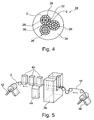
- FIG Fig. 4 An exemplary conductor structure of an induction cable 24 is shown in FIG Fig. 4 shown.
- the induction cable 24 then has a total of three elements 26, each formed of a plurality of stranded cable cores 2.
- each element 26 has a central optical waveguide fiber 28, which is surrounded concentrically by a first core layer with six cable cores 2. This first core layer is then surrounded by a second core layer in the embodiment consisting of twelve individual cable cores 2. The individual core layers are produced in a stranding process.
- a filling element 30 is arranged in particular glass fiber or aramid.
- the first layer with the six stranded cable cores 2 can - as shown in the embodiment - be surrounded by an intermediate casing 32, for example made of silicone.
- the three elements 26 thus constructed are in turn stranded together and then surrounded with a cable sheath 34, in particular made of silicone.
- the elements 26 each have, for example, a diameter of about 10 mm.
- the entire cable 24 has a diameter of, for example, about 25 mm.
- this induction cable 24 is also suitable for other applications, eg. B. for installation in a hall floor of a production workshop for controlling industrial robots, which proceed on the hall floor. Or for heating, for example, oil-carrying pipes (pipeline).
- the method for producing the cable core 2 is based on the Fig. 5 explained in more detail.
- the rough core 14 is provided on a supply reel 36 and guided by this on various pulleys a machine 38 and therethrough, then passed through several partially optional further processing and monitoring stations 40 and at the end of the manufacturing process immediately from a take-up reel 42 as finished cable core 2 wound up.
- This cable core 2 is then available for the actual manufacturing process of the cable 24 by stranding processes.
- the production of the cable core 2 from the rough core 14 is therefore carried out in total in a continuous, ongoing process during a rewinding operation.
- the raw core 14 is severed and subsequently bonded to the connector 8.
- the processing machine 38 includes an injection molding tool for on-line forming the connector 8 by an injection molding process.
- the raw core 14 is first held at the intended separation point 6 of two gripping elements, then separated, in which case the two wire ends 16 are pulled apart by a desired distance of 1 cm to 2 cm.
- the wire ends 16 are inserted into the injection mold.
- this preferably has two shell halves, which moves perpendicular to the cable longitudinal direction 4 to the wire ends 16 and encloses them.
- the injection molding compound is introduced. After a certain cooling time, the injection mold opens again and the cable core 2 is continued.
- the prefabricated connector 8 is provided here in the processing machine 38.
- the wire ends 16 are inserted into the sleeve sections 22 with the aid of the gripping elements.
- the cohesive bonding of the wire ends 16 within the connector 8 takes place, for example, by tempering and pressing.
- the entire production process as described in US Pat Fig. 5 is controlled by a control unit 44, for example.
Landscapes
- Geology (AREA)
- Life Sciences & Earth Sciences (AREA)
- Engineering & Computer Science (AREA)
- Mining & Mineral Resources (AREA)
- Physics & Mathematics (AREA)
- Environmental & Geological Engineering (AREA)
- Fluid Mechanics (AREA)
- General Life Sciences & Earth Sciences (AREA)
- Geochemistry & Mineralogy (AREA)
- Electromagnetism (AREA)
- Processing Of Terminals (AREA)
- Manufacturing Of Electric Cables (AREA)
- Cable Accessories (AREA)
- Insulated Conductors (AREA)
Description
- Die Erfindung betrifft ein Verfahren zur Herstellung einer Kabelader mit einem von einer Isolierung umgebenen Leiter für ein Kabel, insbesondere für ein Induktionskabel. Die Erfindung betrifft weiterhin eine derartige Kabelader sowie ein Kabel, insbesondere ein Induktionskabel mit einer Mehrzahl derartiger Kabeladern. Die Kabeladern weisen jeweils einen von einer Isolierung umgebenen Leiter auf und sind in Kabellängsrichtung an vorgegebenen Längenpositionen an Trennstellen unterbrochen.
- Ein derartiges Kabel dient insbesondere zur Verwendung als ein sogenanntes Induktionskabel zur Ausbildung eines oder mehrerer Induktionsfelder. Das Kabel ist insbesondere zur induktiven Heizung von Ölsand- und/oder Schwerstöllagerstätten vorgesehen. Eine derartige Anwendung eines solchen Induktionskabels ist beispielsweise aus der
EP 2 250 858 B1 zu entnehmen. Die sich durch diese Anwendung ergebenden technischen Randbedingungen werden durch das nachfolgend beschriebene Kabel erfüllt. - Zum Aufbau der Induktionsfelder bzw. der induktiven Heizung ist es erforderlich, dass die einzelnen Adern des Kabels an definierten Trennstellen in einem Rastermaß mit definierter Länge von beispielsweise mehreren 10 m getrennt sind. Innerhalb des Kabels sind mehrere Adern vorzugsweise zu Leitergruppen zusammengefasst, wobei die Trennstellen oder Unterbrechungen der Adern einer jeweiligen Leitergruppe an der gleichen Längenposition liegt.
- Ein derartiges Kabel wird im Boden (Ölsand) verlegt und dient zur induktiven Erwärmung des Ölsandes, um das im Ölsand gebundene Öl zu verflüssigen und geeignet aufzufangen.
- Beispielsweise wird in der
DE 10 2007 040605 B3 eine Vorrichtung zur "in situ"-Förderung von Bitumen oder Schwerstöl aus Ölsand-Lagerstätten als Reservoir beschrieben, wobei zur Verringerung der Viskosität des Bitumens oder Schwerst-Öls wenigstens eine elektrische/elektromagnetische Heizung vorgesehen ist. In vorgegebener Tiefe des Reservoirs sind dazu wenigstens zwei linear ausgedehnte Leiter parallel in horizontaler Ausrichtung geführt und die Enden der Leiter sind innerhalb oder außerhalb der Reservoirs elektrisch leitend verbunden. Zusammen bilden die Leiter eine Leiterschleife, die einen vorgegebenen komplexen Widerstand realisiert. Außerhalb des Reservoirs sind die Leiter an einen externen Wechselstromgenerator für elektrische Leistung angeschlossen, wobei die Induktivität der Leiterschleife abschnittsweise kompensiert ist. - Diese Technik ist noch vergleichsweise jung und befindet sich noch in der Erprobungsphase. Für großtechnische Anwendungen im industriellen Maßstab ist eine prozesstechnisch sichere und kostengünstige Herstellung eines derartigen Induktionskabels, das eine Länge von mehreren km haben kann, von Vorteil.
- Entsprechend liegt der vorliegenden Erfindung die Aufgabe zugrunde, ein prozesstechnisch sicheres und zuverlässiges Herstellen eines derartigen Kabels zu ermöglichen und ein entsprechendes Kabel anzugeben.
- Die Aufgabe wird gemäß der Erfindung gelöst durch ein Verfahren zur Herstellung einer Kabelader mit den Merkmalen des Anspruchs 1. Die Kabelader umfasst einen von einer Isolierung umgegebenen Leiter und ist für die Verwendung in einem Induktionskabel ausgebildet. Hierzu ist die Kabelader in Kabellängsrichtung an vorgegebenen Längenpositionen an Trennstellen unterbrochen. Zur Herstellung einer derartigen Kabelader wird zunächst eine Rohader fortlaufend, also in einem kontinuierlichen Prozess einer Bearbeitungsmaschine zugeführt. Die Rohader wird in der Bearbeitungsmaschine widerkehrend, insbesondere regelmäßig an vorgegebenen Längenpositionen, an einer jeweiligen Trennstelle getrennt, so dass zwei Aderenden vorliegen. Die freien Aderenden werden dabei von einem Greifelement der Bearbeitungsmaschine gegriffen und in Kabellängsrichtung auseinander gezogen. Anschließend werden die beiden Aderenden wieder mit einem Verbinder miteinander verbunden, so dass wieder ein durchgehender Strang hergestellt ist. Der Verbinder weist dabei ein isolierendes, insbesondere aus einem massiven Material gebildetes Zwischenstück auf, welches zwischen den beiden Aderenden angeordnet ist und diese um einen vorgegebenen Abstand voneinander trennt.
- Durch diese Ausgestaltung ist ein prozesssicheres und automatisiertes Herstellverfahren für eine derartige Kabelader ermöglicht. Aus den derart vorbereiteten Kabeladern wird in einem sich daran anschließenden Verfahrensschritt das eigentliche Kabel hergestellt.
- Im Sinne eines ökonomischen Herstellprozesses ist in besonders vorteilhafter Ausgestaltung ein Umspritzen der Aderenden zur Ausbildung des Verbinders vorgesehen. Hierzu ist eine Spritzgussform als Teil der Bearbeitungsmaschine vorgesehen, die während des kontinuierlichen Prozesses die beiden voneinander getrennten Aderenden an der Trennstelle umschließt. Anschließend wird die Spritzgussmasse aus einem geeigneten Kunststoff-Isolationsmaterial eingespritzt, so dass der Verbinder mit dem isolierenden Zwischenstück zwischen den Aderenden und mit die Aderenden umgebende Hülsenabschnitte ausgebildet wird.
- Im Hinblick auf das gewünschte Einsatzgebiet für die Verwendung in einem Induktionskabel sind die Aderenden innerhalb des Verbinders dicht einliegend umschlossen, insbesondere luftdicht und darüber hinaus auch luftleer. Die Aderenden sind daher innerhalb des Materials des Verbinders vollständig und ohne Gaseinschlüsse eingebettet. Dies wird durch das bevorzugte Spritzverfahren in besonders einfacher Weise erreicht.
- Alternativ zu dem Spritzverfahren wird ein vorzugsweise ebenfalls als Spritzgussteil ausgebildeter Verbinder als vorgefertigtes Bauteil der Bearbeitungsmaschine zugeführt und die Aderenden werden in gegenüberliegende Hülsenabschnitten des Verbinders eingeführt und anschließend werden diese Hülsenabschnitte mit den Aderenden verbunden.
- Im Hinblick auf die angestrebte dicht umschließende Anbindung des Verbinders an die Isolation wird diese mit dem Material des Verbinders vorzugsweise stofflich verbunden. Dies erfolgt insbesondere durch eine Wärmebehandlung und der Verwendung von geeigneten Materialien, die bei Erwärmung zumindest erweichen bzw. teilweise aufschmelzen. Als Material sowohl für den Verbinder als auch für die zumindest äußerste Lage der Isolierung der Kabelader wird daher vorzugsweise ein thermoplastisches Material verwendet.
- Entsprechend wird daher auch für den Verbinder einerseits und für die Isolierung andererseits, zumindest für eine äußere Isolationslage, ein ähnliches und insbesondere ein gleiches Material eingesetzt. Dies ist insbesondere ein hochtemperaturbeständiger Kunststoff, vorzugsweise PFA (Perfluoralkoxy-Polymer).
- Der Verbinder sowie zumindest angrenzende Teilstücke der Ader, vorzugsweise die gesamte Ader werden, mit einer Bandierung, insbesondere aus PTFE (Polytetrofluorethylen) umgeben. Diese wird vorzugsweise wiederrum einer Temperaturbehandlung, insbesondere einem Sinterprozess, unterzogen, um sie möglichst stoffschlüssig mit der Isolation der Ader sowie dem Verbinder zu verbinden. Dadurch wird insgesamt eine torsionssteife Leitungsader erzeugt, die an definierten Trennstellen elektrisch unterbrochen ist. An den Trennstellen sind die jeweiligen Aderenden über den jeweiligen Verbinder miteinander gekoppelt unter Freilassung des Isolationszwischenstückes, wodurch quasi ein Fenster gebildet ist. Durch das Einschmelzen der Aderenden in der Hülse insbesondere auch in Verbindung mit der aufgesinnterten PTFE-Bandierung ist neben der hohen Torsionssteifigkeit auch eine hohe Zugfestigkeit insbesondere im Bereich des Verbinders erzielt.
- Im Hinblick auf ein möglichst ökonomisches Verfahren erfolgt die Herstellung der Kabelader im Laufe eines Umspulvorgangs. Die Rohader wird hierbei auf einer Abwickelspule als Endlos-Ware bereitgestellt und von dieser abgewickelt, durch die Bearbeitungsmaschine hindurch geführt und anschließend nach dem Anbringen der einzelnen Verbinder von einer Aufwickelspule wieder aufgerollt.
- Im Laufe dieses Herstellungsverfahrens wird in zweckdienlicher Weiterbildung die Kabelader einer Online-Qualitätskontrolle unterzogen, d.h. es wird kontinuierlich die Qualität der Verbindungen an den Trennstellen überprüft.
- In erster Linie wird hierbei eine elektrische Überprüfung der Verbinder vorgenommen. Hierbei wird der Verbinder - nachdem er nach einer definierten Abkühlzeit aus der Spritzgussform entnommen wurde - einem Teilentladungstest unterzogen. Hierbei wird überprüft, ob der Verbinder bei einer vorgegebenen Spannung die gewünschten Isolationseigenschaften aufweist, bevor die Kabelader auf die Aufwickelspule aufgespult wird.
- Ergänzend ist bei Bedarf eine mechanische (Zug-) Prüfeinrichtung in die Prozesskette integriert. Daneben sind vorzugsweise auch - soweit erforderlich - weitere Bearbeitungseinheiten in der Prozesskette integriert, wie beispielsweise eine zusätzliche Schweißeinheit oder auch eine Bandiereinheit. Ergänzend ist insbesondere auch eine zusätzliche Temperiereinheit insbesondere zur thermischen Behandlung (Sinterprozess) der aufgebrachten Bandierung angeordnet.
- Am Ende dieses Herstellungsprozesses der Kabelader steht diese daher auf einer Spule aufgewickelt für die weitere Verarbeitung zur Verfügung. In einem nachfolgenden Verfahrensschritt, der zu einem späteren Zeitpunkt und auch an einem anderen Ort erfolgen kann, werden dann die einzelnen Kabeladern zur Herstellung des eigentlichen Kabels herangezogen. Dieses weist am Ende mehrere derartige Kabeladern auf, die von einem gemeinsamen Kabelmantel umgeben sind. Zur Herstellung des Kabels werden die einzelnen Kabeladern dabei vorzugsweise ggf. auch mehrfach miteinander verseilt.
- Die einzelnen Kabeladern werden dabei derart zueinander positioniert, dass die einzelnen Trennstellen zumindest einer Gruppe von Kabeladern an der gleichen Längenposition angeordnet sind. Es können mehrere Gruppen an Kabeladern vorgesehen sein, (beispielsweise 2 oder 3) deren Trennstellen jeweils an der gleichen Längenposition orientiert sind, wobei die Trennstellen der Kabeladern verschiedener Gruppen zueinander versetzt angeordnet sind.
- Der Abstand zwischen den Verbinder und damit den Trennstellen liegt typischerweise bei mehreren Metern, insbesondere bei mehreren 10 Metern. Die Trennstellen sind dabei in einem vorgegebenen, insbesondere konstanten Rastermaß angeordnet.
- Das Kabel umfasst dabei zweckdienlicherweise mehrere verseilte Elemente, die auf der einen Seite aus mehreren miteinander verseilten Kabeladern bestehen und selbst wiederum miteinander verseilt sind. Das derart hergestellte Kabel weist eine Länge von typischerweise zumindest mehreren 100m bis mehrere km auf. Vor dem Hintergrund des angestrebten Anwendungszweckes, nämlich als Induktionskabel zum Erwärmen von Ölsanden, ist es insgesamt hochtemperaturbeständig für eine Temperatur größer 200°C ausgebildet. Entsprechend sind auch die verwendeten Materialien für eine derart hohe Temperatur ausgebildet.
- Durch dieses Verfahren ist daher ein vollautomatisiertes Herstellen eines derartigen Kabels ermöglicht, wobei auf herkömmliche Kabelherstellschritte, wie den Verseilprozess etc. zurückgegriffen wird.
- Die Aufgabe wird gemäß der Erfindung weiterhin gelöst durch eine Kabelader mit den Merkmalen des Anspruchs 8 sowie durch ein Kabel mit den Merkmalen des Anspruchs 15. Die im Hinblick auf das Herstellverfahren angeführten Vorteile und bevorzugten Ausgestaltungen sind sinngemäß auch auf die Kabelader sowie das Kabel übertragbar.
- Ein Ausführungsbeispiel wird anhand der Figuren näher erläutert. Diese zeigen jeweils in vereinfachten Darstellungen:
- Fig 1
- eine ausschnittsweise Schnittdarstellung einer an einer Trennstelle über einen Verbinder verbundenen Kabelader gemäß einer ersten Variante,
- Fig 2
- eine zu
Fig 1 vergleichbare Darstellung gemäß einer zweiten Variante, - Fig 3
- eine Kabelader in Seitenansicht,
- Fig 4
- eine Querschnittansicht eines Induktionskabels, sowie
- Fig 5
- eine stark vereinfachte Produktionsstraße für die Herstellung der Kabelader.
- Aus den
Fig 1 bis 3 ist in verschiedenen Darstellungen eine Kabelader 2 dargestellt, die sich in Kabellängsrichtung 4 erstreckt, und die an periodisch widerkehrenden Trennstellen 6 jeweils einen Verbinder 8 aufweist. Die Trennstellen 6 sind in einem vorgegebenen Rastermaß a ausgebildet. - Die Kabelader 2 umfasst einen zentralen elektrischen Leiter 10, welcher von einer Isolierung 12 umgeben ist. Bei der Isolierung 10 handelt es sich vorzugsweise um eine mehrschichtige Isolierung 12 aus unterschiedlichen Isolierwerkstoffen, die jeweils hochtemperaturbeständig sind. Gemäß einer ersten Variante besteht die Isolierung aus lediglich einer Isolationsschicht vorzugsweise aus PFA. Gemäß einer zweiten Variante besteht die Isolierung 12 aus zwei Schichten, bevorzugt eine Schicht aus PFA und eine weitere aus einem PTFE, das insbesondere als Bandierung aufgebracht ist. Gemäß einer dritten Variante sind drei Schichten vorgesehen, wobei bevorzugt eine PTFE-Bandierung sandwichartig zwischen zwei PFA-Isolations-Schichten eingebettet ist. Schließlich ist gemäß einer vierten Variante ein insgesamt vierschichtiger Aufbau vorgesehen, bei dem wiederum in bevorzugter Ausgestaltung zwei Zwischenlagen zwischen zwei PFA-Beschichtungen eingebettet sind. Die beiden Zwischenlagen sind dabei vorzugsweise ein bandiertes PTFE sowie ein bandierter Glimmer. Die Varianten mit einer zwischen zwei PFA-Lagen eingebetteten und insbesondere als Bandierung ausgebildeten Zwischenlage zeigt eine besonders gute machanische Stabilität.
- Als elektrischer Leiter 10 wird ein Draht, insbesondere ein Kupferdraht und vorzugsweise ein vernickelter Kupferdraht eingesetzt. Alternativ kann auch ein Litzendraht, beispielsweise ein Kupfer- oder ein vernickelter Kupfer-Litzendraht bestehend aus einer Vielzahl von einzelnen Drähten eingesetzt werden.
- Aus einer Rohader 14 bestehend aus dem Leiter 10 und der Isolierung 12 ist die Kabelader 2 ausgebildet. Hierzu ist die Rohader 14 an den Trennstellen 6 unterbrochen, so dass zwei gegenüberliegende Aderenden 16 ausgebildet sind. Diese sind über den Verbinder 8 miteinander verbunden. In beiden Ausführungsvarianten der
Fig 1 und 2 ist gemeinsam, dass der Verbinder 8 mit der Isolierung 12 der Aderenden 16 eine stoffschlüssige Verbindung eingeht. Ergänzend ist bei beiden Ausführungsvarianten noch eine zusätzliche Bandierung 18, insbesondere aus PTFE vorgesehen, mit der der Verbinder und die angrenzenden Teilstücke der Rohader 14 umwickelt sind. Auch diese Bandierung 18 ist vorzugsweise ebenfalls stoffschlüssig mit dem Verbinder 8 und der Isolierung 12 verbunden. - Der Verbinder 8 ist in beiden Fällen gebildet durch ein massives Zwischenstück 20, an das sich jeweils gegenüberliegend Hülsenabschnitte 22 anschließen, in denen die Aderenden 16 gasfrei und gasdicht einliegen.
- Bei beiden Verbindern 8 handelt es sich um Spritzgussteile. Als Material wird vorzugsweise das gleiche Material-wie die äußerste Hülle der Isolierung 12 verwendet, insbesondere PFA. Aufgrund der Verwendung eines Thermoplasten lässt sich die gewünschte stoffschlüssige Verbindung in einfacher Weise durch die Einbringung von Wärme erzielen.
- In prozesstechnisch besonders günstiger Weise geschieht dies bei der Ausführungsvariante gemäß
Fig 1 dadurch, dass der Verbinder 8 direkt an der Rohader 14 mit den getrennten Aderenden 16 durch einen Spritzgussprozess ausgebildet wird. - Im Unterschied hierzu ist bei der Ausführungsvariante der
Fig 2 beim Herstellprozess ein vorgefertigter Verbinder 8 bereitgestellt, in den die Aderenden 16 jeweils eingeführt werden und anschließend werden die Hülsenabschnitte 22 mit den Aderenden 16 beispielsweise durch Pressen und/oder Wärmebehandlung stoffschlüssig verbunden. - Der Verbinder 8 weist insgesamt eine Länge vorzugsweise von mehreren cm, beispielsweise im Bereich von 5 cm bis 15 cm auf. Die Länge des Zwischenstücks 20 liegt dabei im Bereich von 5 mm bis 20 mm. Der Durchmesser der Rohader 14 und damit in etwa der Innendurchmesser der Hülsenabschnitte 22 liegt vorzugsweise etwa im Bereich von 1 mm bis 3 mm. Die Wandstärke der Hülsenabschnitte 22 liegt vorzugsweise im Bereich von 0,3 mm bis 1 mm. Insgesamt ist der Verbinder 8 symmetrisch aufgebaut. Das Rastermaß a zwischen den Verbindern 8 liegt im Bereich von mehreren 10 m.
- Ein beispielhafter Leiteraufbau eines Induktionskabels 24 ist in
Fig 4 dargestellt. - Das Induktionskabel 24 weist danach insgesamt drei Elemente 26 auf, die jeweils aus einer Mehrzahl von miteinander verseilten Kabeladern 2 gebildet sind. Jedes Element 26 weist im Ausführungsbeispiel eine zentrale Lichtwellenleiter-Faser 28 auf, die von einer ersten Adernlage mit sechs Kabeladern 2 konzentrisch umgeben ist. Diese erste Adernlage wird anschließend von einer zweiten Adernlage im Ausführungsbeispiel bestehend aus zwölf einzelnen Kabeladern 2 umgeben. Die einzelnen Adernlagen sind in einem Verseilprozess hergestellt. Im Zwickel der drei Elemente 26 ist noch ein Füllelement 30 insbesondere aus Glasseide oder Aramid angeordnet. Die erste Lage mit den sechs miteinander verseilten Kabeladern 2 kann - wie im Ausführungsbeispiel dargestellt - von einem Zwischenmantel 32, beispielsweise aus Silikon umgeben sein. Die drei derart aufgebauten Elemente 26 werden wiederrum miteinander verseilt und anschließend mit einem Kabelmantel 34, insbesondere aus Silikon, umgeben. Die Elemente 26 weisen dabei jeweils beispielsweise einen Durchmesser von etwa 10 mm auf. Das gesamte Kabel 24 weist einen Durchmesser beispielsweise von etwa 25 mm auf.
- Grundsätzlich eignet sich dieses Induktionskabel 24 auch für andere Anwendungen, z. B. für eine Verlegung in einem Hallenboden einer Produktionswerkstätte zur Steuerung von Industrierobotern, die auf dem Hallenboden verfahren. Oder zur Beheizung von beispielsweise öltransportierenden Rohren (Pipeline).
- Das Verfahren zur Herstellung der Kabelader 2 wird anhand der
Fig 5 näher erläutert. Die Rohader 14 wird auf einer Abwickelspule 36 bereitgestellt und von dieser über verschiedene Umlenkrollen einer Bearbeitungsmaschine 38 zu und durch diese hindurch geführt, anschließend durch mehrere teilweise fakultative weitere Bearbeitungs- und Überwachungsstationen 40 geführt und am Ende des Herstellprozesses sogleich wieder von einer Aufwickelspule 42 als fertig hergestellte Kabelader 2 aufgewickelt. Diese Kabelader 2 steht dann für den eigentlichen Herstellvorgangs des Kabels 24 durch Verseilprozesse zur Verfügung. - Die Herstellung der Kabelader 2 aus der Rohader 14 erfolgt daher insgesamt in einem kontinuierlichen, laufenden Verfahren während eines Umspulvorgangs.
- Innerhalb der Bearbeitungsmaschine 38 erfolgt das Trennen der Rohader 14 und das anschließende Verbinden mit dem Verbinder 8. In der bevorzugten Ausführungsvariante enthält die Bearbeitungsmaschine 38 ein Spritzgusswerkzeug zur Online-Ausbildung des Verbinders 8 durch einen Spritzgießprozess. Hierzu wird zunächst die Rohader 14 an der vorgesehenen Trennstelle 6 von zwei Greifelementen gehalten, anschließend getrennt, wobei dann die beiden Aderenden 16 um einen gewünschten Abstand von 1 cm bis 2 cm auseinander gezogen werden. Schließlich werden die Aderenden 16 in die Spritzgussform eingelegt. Hierzu weist diese vorzugsweise zwei Schalenhälften auf, die senkrecht zur Kabellängsrichtung 4 an die Aderenden 16 heranfährt und diese umschließt. Anschließend wird die Spritzgussmasse eingebracht. Nach einer gewissen Abkühlzeit öffnet die Spritzgussform wieder und die Kabelader 2 wird weitergeführt. Nach diesem Prozess des Anbringens des Verbinders 8 erfolgt noch in bevorzugter Ausgestaltung die Anbringung der Bandierung 18 mit anschließendem Sintern zur stoffschlüssigen Befestigung der Bandierung 18. Dies erfolgt beispielsweise in einer der nachfolgenden Bearbeitungsstationen 40. Eine weitere Bearbeitungsstation 40 ist als Überprüfungsstation zur Online-Qualitätskontrolle ausgebildet. Untersuchungen haben gezeigt, dass bei der hier gewählten Ausgestaltung mit dem unmittelbaren Umspritzen der Aderenden 16 eine sehr gute mechanische Verbindung erzielt wird, so dass auf eine separate mechanische Zugprüfung für den jeweiligen Verbinder 8 verzichtet wird.
- Auch bei der Ausgestaltung der
Fig 2 wird ein zumindest ähnlicher Herstellprozess eingesetzt. Anstelle des Online-Umspritzens wird hier jedoch in der Bearbeitungsmaschine 38 der vorgefertigte Verbinder 8 bereitgestellt. Die Aderenden 16 werden mit Hilfe der Greifelemente in die Hülsenabschnitte 22 eingeführt. In einem nachfolgenden Prozessschritt erfolgt beispielsweise durch Erwämren und Verpressen das stoffschlüssige Verbinden der Aderenden 16 innerhalb des Verbinders 8. Der gesamte Herstellprozess wie er inFig 5 dargestellt ist, wird beispielsweise durch eine Steuereinheit 44 gesteuert. -
- 2
- Kabelader
- 4
- Kabellängsrichtung
- 6
- Trennstelle
- 8
- Verbinder
- 10
- Leiter
- 12
- Isolierung
- 14
- Rohader
- 16
- Aderende
- 18
- Bandierung
- 20
- Zwischenstück
- 22
- Hülsenabschnitt
- 24
- Induktionskabel
- 26
- Element
- 28
- Lichtwellenleiter-Faser
- 30
- Füllelement
- 32
- Zwischenmantel
- 34
- Kabelmantel
- 36
- Abwickelspule
- 38
- Bearbeitungsmaschine
- 40
- Bearbeitungsstation/Überwachungsstation
- 42
- Aufwickelspule
- 44
- Steuereinheit
- a
- Rastermaß
Claims (15)
- Verfahren zur Herstellung einer Kabelader (2) mit einem von einer Isolierung (12) umgebenen Leiter für ein Kabel, insbesondere für ein Induktionskabel (24),
dadurch gekennzeichnet,
dass eine Rohader (14) fortlaufend einer Bearbeitungsmaschine (38) zugeführt wird und dort wiederkehrend- an vorgegebenen Längenpositionen an einer jeweiligen Trennstelle (6) getrennt wird, so dass an der Trennstelle (6) zwei Aderenden (16) vorliegen- die Aderenden (16) in Kabellängsrichtung (4) auseinandergezogen werden,- die beiden Aderenden (16) wieder mit einem Verbinder (8) verbunden werden, wobei dieser ein isolierendes Zwischenstück (20) aufweist, welches die Aderenden (16) um einen vorgegebenen Abstand voneinander trennt. - Verfahren nach Anspruch 1,
dadurch gekennzeichnet,
dass die voneinander getrennten Aderenden (16) zur Ausbildung des Verbinders (8) umspritzt werden. - Verfahren nach einem der vorhergehenden Ansprüche,
dadurch gekennzeichnet,
dass ergänzend eine Bandierung (18) auf die Kabelader (2) und den Verbinder (8) aufgebracht wird. - Verfahren nach einem der vorhergehenden Ansprüche,
dadurch gekennzeichnet,
dass das Trennen und Verbinden der Rohader (14) bei einem Umspulprozess erfolgt. - Verfahren nach einem der vorhergehenden Ansprüche,
dadurch gekennzeichnet,
dass mehrere der derart vorbereiteten Kabeladern (2) durch einen Verseilprozess zusammengefügt und mit einem gemeinsamen Kabelmantel (34) umgeben werden. - Kabelader (2) für ein sich in einer Kabellängsrichtung (4) erstreckendes Kabel, insbesondere für ein Induktionskabel (24), mit mehreren derartigen Kabeladern (2), die jeweils einen von einer Isolierung umgebenen Leiter (10) aufweisen, wobei die jeweilige Kabelader (2) in Kabellängsrichtung (4) an vorgegebenen Längenpositionen an Trennstellen (6) unter Ausbildung zweier Aderenden (16) unterbrochen ist,
dadurch gekennzeichnet,
dass zur Verbindung der Aderenden (16) ein sich in Kabellängsrichtung (4) erstreckender Verbinder (8) mit einem isolierenden Zwischenstück (20) angeordnet ist und die Aderenden (16) in Kabellängsrichtung (4) beidseitig des Zwischenstücks (20) am Verbinder (8) befestigt sind. - Kabelader (2) nach Anspruch 6,
dadurch gekennzeichnet,
dass der Verbinder (8) beidseitig des Zwischenstücks (20) jeweils eine in Kabellängsrichtung (4) erstreckenden Hülsenabschnitt (22) aufweist, in denen die Aderenden (16) einliegen. - Kabelader (2) nach Anspruch 6 oder 7,
dadurch gekennzeichnet,
dass der Verbinder (8) als ein Spritzgussteil ausgebildet ist. - Kabelader (2) nach einem der Ansprüche 6 bis 8,
dadurch gekennzeichnet,
dass der Verbinder (8) durch Umspritzen der Aderenden (16) ausgebildet ist. - Kabelader (2) nach einem der Ansprüche 6 bis 9,
dadurch gekennzeichnet,
dass die Trennstellen (6) sich in einem vorgegebenen Rastermaß (a) wiederholen, wobei das Rastermaß (a) im Bereich von mehreren Metern liegt. - Kabelader (2) nach einem der Ansprüche 6 bis 10,
dadurch gekennzeichnet,
dass die Isolierung (12) mit dem Verbinder (8) stofflich verbunden ist. - Kabelader (2) nach einem der Ansprüche 6 bis 11,
dadurch gekennzeichnet,
dass der Verbinder (8) sowie die Isolierung (12) aus einem ähnlichen und insbesondere gleichen Material bestehen. - Kabelader (2) nach einem der Ansprüche 6 bis 12, gekennzeichnet durch eine umlaufende Bandierung (18) aus einem hochtemperaturbeständigen Kunststoff, die den Verbinder (8) sowie zumindest angrenzende Teilstücke der Kabelader (2) umgibt.
- Kabelader (2) nach einem der Ansprüche 6 bis 13,
dadurch gekennzeichnet,
dass die Bandierung (18) mit dem Verbinder (8) und/oder mit der Isolierung (12) stofflich verbunden ist. - Kabel, insbesondere Induktionskabel (24), bei dem mehrere Kabeladern (2) nach einem der Ansprüche 6 bis 14 miteinander verseilt und von einem Kabelmantel (34) umgeben sind.
Applications Claiming Priority (2)
| Application Number | Priority Date | Filing Date | Title |
|---|---|---|---|
| DE102011087680 | 2011-12-02 | ||
| PCT/EP2012/004929 WO2013079201A1 (de) | 2011-12-02 | 2012-11-29 | Verfahren zur herstellung einer kabelader mit einem von einer isolierung umgebenen leiter für ein kabel, insbesondere für ein induktionskabel, sowie kabelader und kabel |
Publications (2)
| Publication Number | Publication Date |
|---|---|
| EP2785968A1 EP2785968A1 (de) | 2014-10-08 |
| EP2785968B1 true EP2785968B1 (de) | 2016-05-04 |
Family
ID=47561503
Family Applications (1)
| Application Number | Title | Priority Date | Filing Date |
|---|---|---|---|
| EP12815990.2A Active EP2785968B1 (de) | 2011-12-02 | 2012-11-29 | Verfahren zur herstellung einer kabelader mit einem von einer isolierung umgebenen leiter für ein kabel, insbesondere für ein induktionskabel, sowie kabelader und kabel |
Country Status (7)
| Country | Link |
|---|---|
| US (1) | US10219326B2 (de) |
| EP (1) | EP2785968B1 (de) |
| CN (1) | CN103987916B (de) |
| CA (1) | CA2857698C (de) |
| EA (1) | EA025554B1 (de) |
| ES (1) | ES2585106T3 (de) |
| WO (1) | WO2013079201A1 (de) |
Cited By (1)
| Publication number | Priority date | Publication date | Assignee | Title |
|---|---|---|---|---|
| WO2021021037A1 (en) | 2019-07-30 | 2021-02-04 | Üntel Kablolari Sanayi̇ Ve Ti̇caret Anoni̇m Şi̇rketi̇ | Cable production system |
Families Citing this family (17)
| Publication number | Priority date | Publication date | Assignee | Title |
|---|---|---|---|---|
| KR101932098B1 (ko) * | 2013-12-19 | 2018-12-24 | 레오니 카벨 게엠베하 | 케이블 및 이의 제조를 위한 방법 |
| WO2015128487A1 (de) | 2014-02-28 | 2015-09-03 | Leoni Kabel Holding Gmbh | Kabel, insbesondere induktionskabel, verfahren zum verlegen eines solchen kabels und verlegehilfe |
| CA2940875C (en) | 2014-02-28 | 2022-03-15 | Leoni Kabel Holding Gmbh | Induction cable, coupling device, and method for producing an induction cable |
| WO2015128491A1 (de) | 2014-02-28 | 2015-09-03 | Leoni Kabel Holding Gmbh | Kabel, insbesondere induktionskabel sowie verfahren zur herstellung eines kabels |
| EA033492B1 (ru) * | 2014-02-28 | 2019-10-31 | Leoni Kabel Holding Gmbh | Токопроводящая жила кабеля, предназначенная для кабеля, в частности индукционного кабеля, кабель и способ изготовления токопроводящей жилы кабеля |
| DE102014206747A1 (de) * | 2014-04-08 | 2015-10-08 | Siemens Aktiengesellschaft | Induktor |
| EP2947262B1 (de) * | 2014-05-21 | 2016-12-14 | Siemens Aktiengesellschaft | Induktor und Verfahren zur Heizung einer geologischen Formation |
| EP2947261B1 (de) * | 2014-05-21 | 2016-12-14 | Siemens Aktiengesellschaft | Induktor und Verfahren zur Heizung einer geologischen Formation |
| EP2947959B1 (de) * | 2014-05-22 | 2016-09-28 | Siemens Aktiengesellschaft | Induktor |
| WO2016186976A1 (en) * | 2015-05-15 | 2016-11-24 | Schlumberger Technology Corporation | Injection molded insulated cable repair |
| JP2017024094A (ja) * | 2015-07-17 | 2017-02-02 | セイコーエプソン株式会社 | ロボットシステムおよびケーブル |
| DE102015215448A1 (de) * | 2015-08-13 | 2017-02-16 | Siemens Aktiengesellschaft | Kabel, Induktor und Verfahren zur Herstellung eines Induktors zur Heizung einer geologischen Formation |
| US11299937B2 (en) | 2019-09-30 | 2022-04-12 | Halliburton Energy Services, Inc. | High pressure dual electrical collet assembly for oil and gas applications |
| JP7575200B2 (ja) | 2020-05-20 | 2024-10-29 | 古河電気工業株式会社 | ケーブル、ケーブルの製造方法、 |
| CN113470871B (zh) * | 2021-06-25 | 2022-09-13 | 海南电网有限责任公司三亚供电局 | 基于生物感应技术的电力电缆防外破装置 |
| CN114613553B (zh) * | 2022-03-21 | 2023-10-20 | 湖北艾克电缆有限公司 | 一种绝缘电缆生产方法 |
| DE102024127078A1 (de) * | 2024-09-19 | 2026-03-19 | Bizlink Industry Germany Gmbh | Kabel mit Kabelabschnitten, welche unterschiedliche Steifigkeiten aufweisen sowie Verfahren zur Herstellung eines solchen Kabels |
Family Cites Families (13)
| Publication number | Priority date | Publication date | Assignee | Title |
|---|---|---|---|---|
| JPS61281406A (ja) * | 1985-06-06 | 1986-12-11 | 株式会社 潤工社 | 伝送線路 |
| GB9718925D0 (en) * | 1997-09-05 | 1997-11-12 | Bicc Plc | Electric cable joints and method of making them |
| US5994682A (en) | 1997-12-08 | 1999-11-30 | Power House Tool, Inc. | Induction heating device with a quick disconnect terminal and method of use |
| US6189611B1 (en) | 1999-03-24 | 2001-02-20 | Kai Technologies, Inc. | Radio frequency steam flood and gas drive for enhanced subterranean recovery |
| JP3641475B2 (ja) | 2002-12-18 | 2005-04-20 | 福農産業株式会社 | マルチングシート用穿孔具 |
| US7105784B2 (en) | 2003-03-24 | 2006-09-12 | Kabushiki Kaisha Toshiba | Fixing device |
| JP2004294560A (ja) * | 2003-03-25 | 2004-10-21 | Toshiba Tec Corp | 誘導加熱を用いた定着装置 |
| CN100424948C (zh) * | 2005-02-18 | 2008-10-08 | 夏云杰 | 现场交联聚乙烯熔接电缆接头工艺方法 |
| US20080267676A1 (en) * | 2007-04-27 | 2008-10-30 | Kabushiki Kaisha Toshiba | Fixing device, coil unit for fixing device and method for manufacturing of coil unit |
| DE102007040605B3 (de) * | 2007-08-27 | 2008-10-30 | Siemens Ag | Vorrichtung zur "in situ"-Förderung von Bitumen oder Schwerstöl |
| DE102008062326A1 (de) | 2008-03-06 | 2009-09-17 | Siemens Aktiengesellschaft | Anordnung zur induktiven Heizung von Ölsand- und Schwerstöllagerstätten mittels stromführender Leiter |
| WO2009135806A1 (de) | 2008-05-05 | 2009-11-12 | Siemens Aktiengesellschaft | Verfahren und vorrichtung zur "in situ"-förderung von bitumen oder schwerstöl |
| FR2947587A1 (fr) | 2009-07-03 | 2011-01-07 | Total Sa | Procede d'extraction d'hydrocarbures par chauffage electromagnetique d'une formation souterraine in situ |
-
2012
- 2012-11-29 ES ES12815990.2T patent/ES2585106T3/es active Active
- 2012-11-29 EA EA201491076A patent/EA025554B1/ru not_active IP Right Cessation
- 2012-11-29 EP EP12815990.2A patent/EP2785968B1/de active Active
- 2012-11-29 CA CA2857698A patent/CA2857698C/en active Active
- 2012-11-29 WO PCT/EP2012/004929 patent/WO2013079201A1/de not_active Ceased
- 2012-11-29 CN CN201280059511.XA patent/CN103987916B/zh not_active Expired - Fee Related
-
2014
- 2014-06-02 US US14/293,109 patent/US10219326B2/en active Active
Cited By (1)
| Publication number | Priority date | Publication date | Assignee | Title |
|---|---|---|---|---|
| WO2021021037A1 (en) | 2019-07-30 | 2021-02-04 | Üntel Kablolari Sanayi̇ Ve Ti̇caret Anoni̇m Şi̇rketi̇ | Cable production system |
Also Published As
| Publication number | Publication date |
|---|---|
| CN103987916A (zh) | 2014-08-13 |
| WO2013079201A1 (de) | 2013-06-06 |
| EA201491076A1 (ru) | 2014-09-30 |
| CN103987916B (zh) | 2017-01-18 |
| EA025554B1 (ru) | 2017-01-30 |
| US10219326B2 (en) | 2019-02-26 |
| CA2857698C (en) | 2019-10-15 |
| US20140263289A1 (en) | 2014-09-18 |
| ES2585106T3 (es) | 2016-10-03 |
| EP2785968A1 (de) | 2014-10-08 |
| CA2857698A1 (en) | 2013-06-06 |
Similar Documents
| Publication | Publication Date | Title |
|---|---|---|
| WO2013079201A1 (de) | Verfahren zur herstellung einer kabelader mit einem von einer isolierung umgebenen leiter für ein kabel, insbesondere für ein induktionskabel, sowie kabelader und kabel | |
| AT511080B1 (de) | Sägeseil zur verwendung in einer seilsägemaschine | |
| DE112015002173T5 (de) | Optische Äquipotential-Fasereinheit für photoelektrische Hochspannungs-Kompositkabel und deren Herstellungsverfahren | |
| EP3183737A1 (de) | Kabelsatz und verfahren zur herstellung eines solchen | |
| DE102014014794B4 (de) | Kabel hoher Steifigkeit, Verwendung, sowie Verfahren zur Herstellung desselben | |
| EP3111040B1 (de) | Kabelader für ein kabel, insbesondere ein induktionskabel, kabel und verfahren zur herstellung einer kabelader | |
| EP3111039B1 (de) | Induktionskabel, kupplungsvorrichtung sowie verfahren zum herstellen eines induktionskabels | |
| DE102016102948A1 (de) | Verfahren und Vorrichtung zur Abdichtung von Kontaktstellen an elektrischen Leitungsverbindungen | |
| DE3243061A1 (de) | Flexibles elektrisches ablaengbares heizelement | |
| EP0907093A1 (de) | Verfahren zur Herstellung eines Metallröhrchens mit optischer Faser | |
| EP2885856B1 (de) | Verfahren zur herstellung einer isolation eines leiters | |
| EP0881730B1 (de) | Flexibler Rohrverbund | |
| DE2357984C2 (de) | Verfahren zur Herstellung von elektrischen Kabeln oder Leitungen | |
| WO2014001061A2 (de) | Temperaturmessvorrichtung, messelement für eine temperaturmessvorrichtung und verfahren zum herstellen der temperaturmessvorrichtung | |
| EP2927912B1 (de) | Flachkabel mit kurzschlussvermeidung im brandfall sowie verwendung und herstellung eines solchen flachkabels | |
| EP2842141B1 (de) | Selbsttragende elektrische leitung | |
| DE2627174C2 (de) | Optische Flachbandleitung | |
| DE2441371C2 (de) | Vorrichtung zum Vernetzen einer mit Polyolefin isolierten Kabelseele | |
| DE2836559B2 (de) | Verfahren zur Herstellung eines Koaxialkabels | |
| EP1071311A1 (de) | Kapselung für das An- oder das Abschlussende eines elektrischen Heizbandkabels und Verfahren zu seiner Herstellung | |
| EP3945532A1 (de) | Verfahren zum herstellen eines kabelbündels, fertigungsanlage zur herstellung eines kabelbündels, sowie kabelbündel | |
| DE102014200874B4 (de) | Verfahren und Anlage zur Herstellung eines konfektionierten Kabels vorbestimmter Länge | |
| WO2015128491A1 (de) | Kabel, insbesondere induktionskabel sowie verfahren zur herstellung eines kabels | |
| DE102022206645A1 (de) | Transfermoldverfahren zum Umspritzen eines elektronischen Bauteils, Moldeinrichtung zum Ausführen des Transfermoldverfahrens | |
| DE102014226543B4 (de) | Hybridkabel, Verfahren zur Herstellung eines solchen und Verwendung eines solchen in einemKraftfahrzeug |
Legal Events
| Date | Code | Title | Description |
|---|---|---|---|
| PUAI | Public reference made under article 153(3) epc to a published international application that has entered the european phase |
Free format text: ORIGINAL CODE: 0009012 |
|
| 17P | Request for examination filed |
Effective date: 20140527 |
|
| AK | Designated contracting states |
Kind code of ref document: A1 Designated state(s): AL AT BE BG CH CY CZ DE DK EE ES FI FR GB GR HR HU IE IS IT LI LT LU LV MC MK MT NL NO PL PT RO RS SE SI SK SM TR |
|
| DAX | Request for extension of the european patent (deleted) | ||
| GRAP | Despatch of communication of intention to grant a patent |
Free format text: ORIGINAL CODE: EPIDOSNIGR1 |
|
| INTG | Intention to grant announced |
Effective date: 20151123 |
|
| GRAS | Grant fee paid |
Free format text: ORIGINAL CODE: EPIDOSNIGR3 |
|
| GRAA | (expected) grant |
Free format text: ORIGINAL CODE: 0009210 |
|
| AK | Designated contracting states |
Kind code of ref document: B1 Designated state(s): AL AT BE BG CH CY CZ DE DK EE ES FI FR GB GR HR HU IE IS IT LI LT LU LV MC MK MT NL NO PL PT RO RS SE SI SK SM TR |
|
| REG | Reference to a national code |
Ref country code: GB Ref legal event code: FG4D Free format text: NOT ENGLISH |
|
| REG | Reference to a national code |
Ref country code: CH Ref legal event code: EP |
|
| REG | Reference to a national code |
Ref country code: AT Ref legal event code: REF Ref document number: 797095 Country of ref document: AT Kind code of ref document: T Effective date: 20160515 |
|
| REG | Reference to a national code |
Ref country code: IE Ref legal event code: FG4D Free format text: LANGUAGE OF EP DOCUMENT: GERMAN |
|
| REG | Reference to a national code |
Ref country code: DE Ref legal event code: R096 Ref document number: 502012007025 Country of ref document: DE |
|
| REG | Reference to a national code |
Ref country code: NL Ref legal event code: FP |
|
| REG | Reference to a national code |
Ref country code: LT Ref legal event code: MG4D |
|
| REG | Reference to a national code |
Ref country code: NO Ref legal event code: T2 Effective date: 20160504 Ref country code: ES Ref legal event code: FG2A Ref document number: 2585106 Country of ref document: ES Kind code of ref document: T3 Effective date: 20161003 |
|
| PG25 | Lapsed in a contracting state [announced via postgrant information from national office to epo] |
Ref country code: LT Free format text: LAPSE BECAUSE OF FAILURE TO SUBMIT A TRANSLATION OF THE DESCRIPTION OR TO PAY THE FEE WITHIN THE PRESCRIBED TIME-LIMIT Effective date: 20160504 Ref country code: FI Free format text: LAPSE BECAUSE OF FAILURE TO SUBMIT A TRANSLATION OF THE DESCRIPTION OR TO PAY THE FEE WITHIN THE PRESCRIBED TIME-LIMIT Effective date: 20160504 |
|
| REG | Reference to a national code |
Ref country code: FR Ref legal event code: PLFP Year of fee payment: 5 |
|
| PG25 | Lapsed in a contracting state [announced via postgrant information from national office to epo] |
Ref country code: LV Free format text: LAPSE BECAUSE OF FAILURE TO SUBMIT A TRANSLATION OF THE DESCRIPTION OR TO PAY THE FEE WITHIN THE PRESCRIBED TIME-LIMIT Effective date: 20160504 Ref country code: RS Free format text: LAPSE BECAUSE OF FAILURE TO SUBMIT A TRANSLATION OF THE DESCRIPTION OR TO PAY THE FEE WITHIN THE PRESCRIBED TIME-LIMIT Effective date: 20160504 Ref country code: GR Free format text: LAPSE BECAUSE OF FAILURE TO SUBMIT A TRANSLATION OF THE DESCRIPTION OR TO PAY THE FEE WITHIN THE PRESCRIBED TIME-LIMIT Effective date: 20160805 Ref country code: PT Free format text: LAPSE BECAUSE OF FAILURE TO SUBMIT A TRANSLATION OF THE DESCRIPTION OR TO PAY THE FEE WITHIN THE PRESCRIBED TIME-LIMIT Effective date: 20160905 Ref country code: HR Free format text: LAPSE BECAUSE OF FAILURE TO SUBMIT A TRANSLATION OF THE DESCRIPTION OR TO PAY THE FEE WITHIN THE PRESCRIBED TIME-LIMIT Effective date: 20160504 Ref country code: SE Free format text: LAPSE BECAUSE OF FAILURE TO SUBMIT A TRANSLATION OF THE DESCRIPTION OR TO PAY THE FEE WITHIN THE PRESCRIBED TIME-LIMIT Effective date: 20160504 |
|
| PG25 | Lapsed in a contracting state [announced via postgrant information from national office to epo] |
Ref country code: CZ Free format text: LAPSE BECAUSE OF FAILURE TO SUBMIT A TRANSLATION OF THE DESCRIPTION OR TO PAY THE FEE WITHIN THE PRESCRIBED TIME-LIMIT Effective date: 20160504 Ref country code: EE Free format text: LAPSE BECAUSE OF FAILURE TO SUBMIT A TRANSLATION OF THE DESCRIPTION OR TO PAY THE FEE WITHIN THE PRESCRIBED TIME-LIMIT Effective date: 20160504 Ref country code: RO Free format text: LAPSE BECAUSE OF FAILURE TO SUBMIT A TRANSLATION OF THE DESCRIPTION OR TO PAY THE FEE WITHIN THE PRESCRIBED TIME-LIMIT Effective date: 20160504 Ref country code: SK Free format text: LAPSE BECAUSE OF FAILURE TO SUBMIT A TRANSLATION OF THE DESCRIPTION OR TO PAY THE FEE WITHIN THE PRESCRIBED TIME-LIMIT Effective date: 20160504 Ref country code: DK Free format text: LAPSE BECAUSE OF FAILURE TO SUBMIT A TRANSLATION OF THE DESCRIPTION OR TO PAY THE FEE WITHIN THE PRESCRIBED TIME-LIMIT Effective date: 20160504 |
|
| REG | Reference to a national code |
Ref country code: DE Ref legal event code: R097 Ref document number: 502012007025 Country of ref document: DE |
|
| PG25 | Lapsed in a contracting state [announced via postgrant information from national office to epo] |
Ref country code: SM Free format text: LAPSE BECAUSE OF FAILURE TO SUBMIT A TRANSLATION OF THE DESCRIPTION OR TO PAY THE FEE WITHIN THE PRESCRIBED TIME-LIMIT Effective date: 20160504 Ref country code: BE Free format text: LAPSE BECAUSE OF NON-PAYMENT OF DUE FEES Effective date: 20161130 Ref country code: PL Free format text: LAPSE BECAUSE OF FAILURE TO SUBMIT A TRANSLATION OF THE DESCRIPTION OR TO PAY THE FEE WITHIN THE PRESCRIBED TIME-LIMIT Effective date: 20160504 |
|
| PLBE | No opposition filed within time limit |
Free format text: ORIGINAL CODE: 0009261 |
|
| STAA | Information on the status of an ep patent application or granted ep patent |
Free format text: STATUS: NO OPPOSITION FILED WITHIN TIME LIMIT |
|
| 26N | No opposition filed |
Effective date: 20170207 |
|
| PG25 | Lapsed in a contracting state [announced via postgrant information from national office to epo] |
Ref country code: SI Free format text: LAPSE BECAUSE OF FAILURE TO SUBMIT A TRANSLATION OF THE DESCRIPTION OR TO PAY THE FEE WITHIN THE PRESCRIBED TIME-LIMIT Effective date: 20160504 |
|
| REG | Reference to a national code |
Ref country code: CH Ref legal event code: PL |
|
| PG25 | Lapsed in a contracting state [announced via postgrant information from national office to epo] |
Ref country code: LI Free format text: LAPSE BECAUSE OF NON-PAYMENT OF DUE FEES Effective date: 20161130 Ref country code: CH Free format text: LAPSE BECAUSE OF NON-PAYMENT OF DUE FEES Effective date: 20161130 |
|
| REG | Reference to a national code |
Ref country code: IE Ref legal event code: MM4A |
|
| PG25 | Lapsed in a contracting state [announced via postgrant information from national office to epo] |
Ref country code: LU Free format text: LAPSE BECAUSE OF NON-PAYMENT OF DUE FEES Effective date: 20161130 |
|
| REG | Reference to a national code |
Ref country code: FR Ref legal event code: PLFP Year of fee payment: 6 |
|
| PG25 | Lapsed in a contracting state [announced via postgrant information from national office to epo] |
Ref country code: IE Free format text: LAPSE BECAUSE OF NON-PAYMENT OF DUE FEES Effective date: 20161129 |
|
| PGFP | Annual fee paid to national office [announced via postgrant information from national office to epo] |
Ref country code: NL Payment date: 20171122 Year of fee payment: 6 |
|
| REG | Reference to a national code |
Ref country code: BE Ref legal event code: MM Effective date: 20161130 |
|
| PG25 | Lapsed in a contracting state [announced via postgrant information from national office to epo] |
Ref country code: HU Free format text: LAPSE BECAUSE OF FAILURE TO SUBMIT A TRANSLATION OF THE DESCRIPTION OR TO PAY THE FEE WITHIN THE PRESCRIBED TIME-LIMIT; INVALID AB INITIO Effective date: 20121129 |
|
| PG25 | Lapsed in a contracting state [announced via postgrant information from national office to epo] |
Ref country code: MK Free format text: LAPSE BECAUSE OF FAILURE TO SUBMIT A TRANSLATION OF THE DESCRIPTION OR TO PAY THE FEE WITHIN THE PRESCRIBED TIME-LIMIT Effective date: 20160504 Ref country code: CY Free format text: LAPSE BECAUSE OF FAILURE TO SUBMIT A TRANSLATION OF THE DESCRIPTION OR TO PAY THE FEE WITHIN THE PRESCRIBED TIME-LIMIT Effective date: 20160504 Ref country code: MC Free format text: LAPSE BECAUSE OF FAILURE TO SUBMIT A TRANSLATION OF THE DESCRIPTION OR TO PAY THE FEE WITHIN THE PRESCRIBED TIME-LIMIT Effective date: 20160504 Ref country code: IS Free format text: LAPSE BECAUSE OF FAILURE TO SUBMIT A TRANSLATION OF THE DESCRIPTION OR TO PAY THE FEE WITHIN THE PRESCRIBED TIME-LIMIT Effective date: 20160504 |
|
| PG25 | Lapsed in a contracting state [announced via postgrant information from national office to epo] |
Ref country code: BG Free format text: LAPSE BECAUSE OF FAILURE TO SUBMIT A TRANSLATION OF THE DESCRIPTION OR TO PAY THE FEE WITHIN THE PRESCRIBED TIME-LIMIT Effective date: 20160504 |
|
| PG25 | Lapsed in a contracting state [announced via postgrant information from national office to epo] |
Ref country code: MT Free format text: LAPSE BECAUSE OF FAILURE TO SUBMIT A TRANSLATION OF THE DESCRIPTION OR TO PAY THE FEE WITHIN THE PRESCRIBED TIME-LIMIT Effective date: 20160504 |
|
| PG25 | Lapsed in a contracting state [announced via postgrant information from national office to epo] |
Ref country code: AL Free format text: LAPSE BECAUSE OF FAILURE TO SUBMIT A TRANSLATION OF THE DESCRIPTION OR TO PAY THE FEE WITHIN THE PRESCRIBED TIME-LIMIT Effective date: 20160504 |
|
| REG | Reference to a national code |
Ref country code: AT Ref legal event code: MM01 Ref document number: 797095 Country of ref document: AT Kind code of ref document: T Effective date: 20171129 |
|
| PG25 | Lapsed in a contracting state [announced via postgrant information from national office to epo] |
Ref country code: AT Free format text: LAPSE BECAUSE OF NON-PAYMENT OF DUE FEES Effective date: 20171129 |
|
| REG | Reference to a national code |
Ref country code: NL Ref legal event code: MM Effective date: 20181201 |
|
| PG25 | Lapsed in a contracting state [announced via postgrant information from national office to epo] |
Ref country code: NL Free format text: LAPSE BECAUSE OF NON-PAYMENT OF DUE FEES Effective date: 20181201 |
|
| REG | Reference to a national code |
Ref country code: ES Ref legal event code: PC2A Owner name: LEONI KABEL GMBH Effective date: 20200609 |
|
| REG | Reference to a national code |
Ref country code: NO Ref legal event code: CHAD Owner name: LEONI KABEL GMBH, DE |
|
| REG | Reference to a national code |
Ref country code: DE Ref legal event code: R082 Ref document number: 502012007025 Country of ref document: DE Representative=s name: FDST PATENTANWAELTE FREIER DOERR STAMMLER TSCH, DE Ref country code: DE Ref legal event code: R081 Ref document number: 502012007025 Country of ref document: DE Owner name: LEONI KABEL GMBH, DE Free format text: FORMER OWNER: LEONI KABEL HOLDING GMBH, 90402 NUERNBERG, DE |
|
| P01 | Opt-out of the competence of the unified patent court (upc) registered |
Effective date: 20230505 |
|
| PGFP | Annual fee paid to national office [announced via postgrant information from national office to epo] |
Ref country code: GB Payment date: 20231123 Year of fee payment: 12 |
|
| PGFP | Annual fee paid to national office [announced via postgrant information from national office to epo] |
Ref country code: ES Payment date: 20231215 Year of fee payment: 12 |
|
| PGFP | Annual fee paid to national office [announced via postgrant information from national office to epo] |
Ref country code: TR Payment date: 20231122 Year of fee payment: 12 Ref country code: NO Payment date: 20231121 Year of fee payment: 12 Ref country code: IT Payment date: 20231130 Year of fee payment: 12 Ref country code: FR Payment date: 20231122 Year of fee payment: 12 Ref country code: DE Payment date: 20231120 Year of fee payment: 12 |
|
| REG | Reference to a national code |
Ref country code: DE Ref legal event code: R119 Ref document number: 502012007025 Country of ref document: DE |
|
| PG25 | Lapsed in a contracting state [announced via postgrant information from national office to epo] |
Ref country code: NO Free format text: LAPSE BECAUSE OF NON-PAYMENT OF DUE FEES Effective date: 20241130 |
|
| GBPC | Gb: european patent ceased through non-payment of renewal fee |
Effective date: 20241129 |
|
| PG25 | Lapsed in a contracting state [announced via postgrant information from national office to epo] |
Ref country code: DE Free format text: LAPSE BECAUSE OF NON-PAYMENT OF DUE FEES Effective date: 20250603 |
|
| PG25 | Lapsed in a contracting state [announced via postgrant information from national office to epo] |
Ref country code: IT Free format text: LAPSE BECAUSE OF NON-PAYMENT OF DUE FEES Effective date: 20241129 |
|
| PG25 | Lapsed in a contracting state [announced via postgrant information from national office to epo] |
Ref country code: GB Free format text: LAPSE BECAUSE OF NON-PAYMENT OF DUE FEES Effective date: 20241129 |
|
| PG25 | Lapsed in a contracting state [announced via postgrant information from national office to epo] |
Ref country code: FR Free format text: LAPSE BECAUSE OF NON-PAYMENT OF DUE FEES Effective date: 20241130 |
|
| REG | Reference to a national code |
Ref country code: ES Ref legal event code: FD2A Effective date: 20260108 |
|
| PG25 | Lapsed in a contracting state [announced via postgrant information from national office to epo] |
Ref country code: ES Free format text: LAPSE BECAUSE OF NON-PAYMENT OF DUE FEES Effective date: 20241130 |