EP2781663B1 - Vanne principale de tricoise avec siège de vanne à inversion - Google Patents
Vanne principale de tricoise avec siège de vanne à inversion Download PDFInfo
- Publication number
- EP2781663B1 EP2781663B1 EP14158881.4A EP14158881A EP2781663B1 EP 2781663 B1 EP2781663 B1 EP 2781663B1 EP 14158881 A EP14158881 A EP 14158881A EP 2781663 B1 EP2781663 B1 EP 2781663B1
- Authority
- EP
- European Patent Office
- Prior art keywords
- hydrant
- valve seat
- main valve
- component
- replacement
- Prior art date
- Legal status (The legal status is an assumption and is not a legal conclusion. Google has not performed a legal analysis and makes no representation as to the accuracy of the status listed.)
- Active
Links
Images

Classifications
-
- E—FIXED CONSTRUCTIONS
- E03—WATER SUPPLY; SEWERAGE
- E03B—INSTALLATIONS OR METHODS FOR OBTAINING, COLLECTING, OR DISTRIBUTING WATER
- E03B9/00—Methods or installations for drawing-off water
- E03B9/02—Hydrants; Arrangements of valves therein; Keys for hydrants
- E03B9/04—Column hydrants
-
- E—FIXED CONSTRUCTIONS
- E03—WATER SUPPLY; SEWERAGE
- E03B—INSTALLATIONS OR METHODS FOR OBTAINING, COLLECTING, OR DISTRIBUTING WATER
- E03B9/00—Methods or installations for drawing-off water
- E03B9/02—Hydrants; Arrangements of valves therein; Keys for hydrants
- E03B9/14—Draining devices for hydrants
Definitions
- the present invention relates to a main hydrant valve comprising a main valve body and a main valve seat, wherein the main valve body is formed by means of a drive device from at least one open position in at least one closed position and vice versa brought.
- the main valve body acts on the main valve seat in the closed position so that the hydrant main valve seals a component of this hydrant with respect to a hydrant inlet.
- Hydrants have been known for a long time and in many different versions. They serve primarily as valves for water extraction from a public (often municipal) or private supply network and supply, for example, the fire department with extinguishing water.
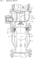
- FIG. 1 An example of an overground hydrant is off CH 675 139 A5 known and here as a vertical section in FIG. 1 displayed.
- This Automatflurhydrant is composed of an inlet pipe 1, a riser 2 and a mounted on the riser 2 essay pipe 3 together.
- the inlet pipe 1 is shown here with an inlet bend 13.
- the inlet pipe 1 can also be designed as a straight piece of pipe (dashed lines, see arrow).
- a seat 4 of a main end valve 5 is arranged, whose valve body 6 is mounted on a projecting into the riser pipe 2 valve rod 7 with a substantially vertical axis 14.
- the spindle extension 17 has an axis 27 and protrudes through a, attached to the upper end of the top tube 3 housing cover 18 and has at the end of a Betuschistsvierkant 19.
- a protective cover base 20 is fixed to which a protective cover upper part 21 is rotatably mounted.
- two side valves 22,23 are installed, the spindles 24,25 each with a Betreli whysvierkant 26 protrude into the space formed by the protective cover parts 20,21 and sealed by seals.
- These side valves 22,23 each have a valve port 28,28 ', which are closed by a screw 29. Through a bore 30, the ventilation of the interior 31 of the hydrant with open side valve 22,23 and thereby emptying via the drain valve 33 is made possible.
- a closure pin 32 is fixed, on which a key with a square hole (not shown) can be placed to open and close the protective cover shell 21.
- Hydrants with such a hydrant main valve have been installed for many years in or on Swiss water distribution networks and have proven themselves.
- the double barrier comprises a main closure valve and an additional shut-off valve 41.
- This hydrant comprises an inlet pipe 1, a bulbous extension 42, a main valve housing 43 and a riser formed as a casing pipe 2.
- a telescopic tube 44 is arranged vertically movable, so that the height of the hydrant 40 of the current installation depth can be adjusted (see also DE 100 28 655 A1 ).
- the valve body 6 of the main end valve 5 is also attached to a valve rod 7 with a substantially vertical axis 14 and formed vertically movable.
- this hydrant has a drain valve 33 in the vicinity of the conical main valve seat 4.
- the spherical beauverrorgan 41 here rests against the annular effetabsperrdichtung 45 to the sealing surfaces 45 ', 45 "of the valve seat 47 and can be moved by moving down the valve stem 7 and attached to the main valve 5 valve stem 46 on the webs 48 are moved downward, whereby the Additional shut-off is opened.
- a hydrant with flat or conical sealing main valve known.
- the valve seat acted upon from below (ie, from the pressure side of the water supply) by the main valve body is annular.
- the valve seat is screwed from the top to stop and has an upper circumferential seal, which seals the valve seat against a between the riser of the hydrant and the main valve housing arranged drainage ring (with drainage opening).
- One of the vertical guide ribs of the main valve body closes the drain hole as soon as the main valve is opened.
- a lower circumferential seal seals the valve seat from the main valve body.
- valve seat can be fitted with a corresponding flange on the inlet bend (in this case on the main valve body) or held on the riser, so that in one case the riser from the combination inlet bend / dewatering ring / valve seat or in another case the inlet bend of the combination riser / drainage ring / valve seat can be separated without the respective combinations must be dismantled.
- an improvement (simplification) of the service work on defective hydrants can already be detected here, in every repair case the inlet bend must be disconnected from the supply network (eg by means of a slide) and at least part of the hydrant dismantled.
- valve seat is annular, is screwed into abutment in the inlet bend and has in the case of GB 26,561 a flat gasket on.
- annular valve seat (with integrated drainage opening) is screwed directly into the upper end of the inlet bend (ie the main valve body).
- a hydrant with flat or conical sealing main valve known.
- an annular insert is placed over the original (old, defective) valve seat in the inlet bend (pressed or screwed in).
- the annular insert is sealed by means of a seal against the inlet bend.
- the main valve body is replaced and replaced by a cylindrical or radial sealing repair valve body whose sealing surfaces are adapted to the annular insert.
- an improvement (simplification) of the service work on defective hydrants can be determined, nevertheless, in every repair case, the main valve body must be replaced.
- This object is achieved with a hydrant main valve comprising the features of independent claim 1.
- inventive, designed as a main valve seat for hydrants change valve seat will be described in more detail below.
- Exemplary above-ground hydrants like those of the prior art (cf. CH 675 139 A5 or. DE 100 46 684 A1 ) and in the FIGS. 1 and 2 are already described.
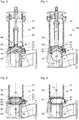
- FIG. 3 shows a vertical section through a hydrant 56 with inserted inventive change-valve seat 53 and a conical sealing main valve body 52 which acts on the change-valve seat 53 in the closed position.
- the hydrant main valve 51 according to the invention comprises a main valve body 52 and a main valve seat 53, wherein the main valve body 52 is adapted to be brought from at least one open position into at least one closed position and vice versa by means of a drive device 54.
- the main valve body 52 acts on the main valve seat 53 in the closed position so that the main hydrant valve 51 seals a component 56 'of this hydrant 56 with respect to a hydrant inlet 57.
- Such hydrant component 56 ' are known to those skilled in general, for example, as a riser 55, jacket tube, intermediate ring, or as arranged between a riser 55 and a hydrant inlet 57 valve housing.
- the riser 55 formed here as a jacket tube, the hydrant member 56 '; an intermediate ring or a separate valve housing arranged between riser 55 and hydrant inlet 57 are known to those skilled in the art but not shown here.
- the main valve seat 53 is designed as a height-adjustable, usable in the hydrant 56 and again removable removable valve seat 53.
- the change-over valve seat 53 is freely movable in the axial direction in the hydrants 56 and can be removed again; ie the movement of the change-valve seat 53 during insertion or removal is not determined by a screw thread or a similar guide.
- the hydrant 56 and / or the change-over valve seat 53 comprise a movable securing element 58 which holds the change-over valve seat 53 in an end position in the hydrant 56.
- the change-valve seat 53 is formed so that it rests sealingly in its end position on an inner surface 73 of a component 56 'of the hydrant 56 and a support surface 59 acts on a component 56' of the hydrant 56.
- the component 56 'of the hydrant 56 with the acted support surface 59, and with the sealing inner surface 73 is typically each formed as a riser 55, jacket tube, intermediate ring, or as the hydrant inlet 57 and a separate arranged between riser 55 and hydrant inlet 57 valve housing.
- both the securing element 58 and the alternating valve seat 53 can be inserted into a hydrant 56 and made removable from a hydrant 56, in which all components 56 'are mounted on the hydrant inlet 57.
- the riser 55 is provided with the hydrant component 56 'with the sealing inner surface 73 and also with the support surface 59.
- This riser 55 is formed here as a telescopic tube surrounding casing pipe.
- the riser tube 55 thus provides the sealing inner surface 73 for both of the preferably two seals 70 disposed on the alternate valve seat 53.
- the riser 55 has a preferably circumferential, annular and integrally formed on the riser 55 support surface 59.
- This support surface 59 is part of an integrally formed on the riser 55, substantially horizontal bead, which here near the lower end of the riser 55 projects radially beyond the inner surface 73 against the interior of the hydrant component 56 '.
- this bead could also be arranged further up in this component 56' of the hydrant 56.
- an intermediate ring or a valve housing (both not shown) between the riser 55 and the hydrant inlet 57 may be arranged.
- This intermediate ring or this valve housing, or else the hydrant inlet 57 could provide the support surface 59 for the replacement valve seat 53 instead of the riser 55, wherein these hydrant components 56 'preferably have a sealing inner surface 73 for the two seals arranged on the replacement valve seat 53 70. Consequently, both seals 70 of the alternating valve seat 53 inserted abut the inner surface 73 of the riser 55, the intermediate ring, the valve housing, or the hydrant inlet 57.
- One or more intermediate rings or a separate, between riser 55 and hydrant inlet 57 arranged valve housing are known in the art but not shown here.
- the replacement valve seat 53 of the hydrant main valve 51 is preferably of annular design and preferably has a cylindrical shape because it can be produced inexpensively and is adapted to the usual shaping of existing hydrants 56.
- an existing hydrant can be easily retrofitted with a change-valve seat 53 for the main hydrant valve 51.
- the change-valve seat 53 may also have a deviating from a cylinder shape, so that it can be used only in a certain orientation in the correspondingly shaped hydrant component 56 '.
- the change-valve seat 53 and the inner surface 73 of the component 56 ' have a cylindrical shape or a shape deviating from a cylinder.
- the shape of the annular replacement valve seat 53 and the inner surface 73 of the component 56 'deviating from a cylinder may have a polygon-like, an oval or an elliptical cross section.
- the change-over valve seat 53 is inserted in a certain orientation in a hydrant component 56 '. If now the change-valve seat 53 and the inner surface 73 of the component 56 'have a cylindrical shape is preferred for aligning the change-valve seat 53 in the component 56' that the change-valve seat 53 at least one guide groove 60 includes in the correct insertion of the change-valve seat 53 in the hydrant 56 at least one with respect to its size and position corresponding directional cam 61 of a component 65 'of the hydrant 56 is immersed (see. Fig. 7A ).
- the change-valve seat 53 comprises at least one directional cam 61, the correct insertion of the change-valve seat 53 in the hydrant 56 in at least one with respect to their size and position corresponding Richtnute 60 of a component 65 'of Hydrant 56 is immersed (cf. Fig. 7B ).
- the component 56 'of the hydrant 56 with the applied support surface 59, with the sealing inner surface 73, and with the Richtnute 60 or with the Richtnocken 61, each selected from a group comprising the riser 55, an intermediate ring, the hydrant inlet 57 and a separate, arranged between the riser 55 and hydrant inlet 57, valve housing comprises.
- fuse element 58 An important task is the fuse element 58, this is to ensure the secure fit of the change-valve seat 53 in the corresponding component 56 'of the hydrant 56. In particular, it is intended to prevent the replacement valve seat 53, e.g. when opening the main valve 51, so when lifting the main valve body 52 from the main valve seat 53, or at a water extraction from the hydrant leaves its final position and slides upwards. There are many alternative ways to construct and arrange such a fuse element 58.
- the securing element 58 is formed as a radially movably resilient retaining ring 62 engaging in a retaining groove 62 of a hydrant component 56 '.
- a securing element 58 is, for example, a Seeger ring from Seeger Orbis GmbH- u. Co. OHG (D-61462 Königstein, Germany), which is designed to engage in an annular retaining groove 62 on the inner surface 73 of the hydrant component 56 '.
- Such, designed as a locking ring securing element 58 may be formed as a separate locking ring and can be used with a corresponding tool freely inserted into the component or captive on the change-valve seat 53 and formed together with this insertable (see. Fig. 8 ).
- the securing element 58 is designed as a securing ring which can be screwed axially into a thread of a hydrant component 56 '.
- a second such locking ring as a screw lock (not shown, but known to any person skilled in the art).
- the securing element 58 is designed as a securing ring which can be inserted axially into a bayonet of a hydrant component 56 '.
- This embodiment has the advantage that (as well as the radially movable spring locking ring), the securing element 58 occupies a blocking position, which can not solve spontaneously.
- the securing element 58 and the change-valve seat 53 with a tool under increased pressure or even under operating pressure (usually up to 16 bar) can be installed and removed.
- FIG. 3 shows a hydrant 56 with inserted inventive change-valve seat 53 and a conical sealing main valve body 52 which acts on the change-valve seat 53 in the closed position.
- the replacement valve seat 53 comprises at least one annular conical sealing surface 63 for the main valve body 52.
- the replacement valve seat 53 comprises at least one annular sealing surface for a main valve body 52, this at least one sealing surface being selected from the group consisting of conical sealing surfaces 63, flat sealing surfaces 63 'and cylindrical sealing surfaces 69 (see. Figs. 7C and 7D ).
- FIG. 4 shows a vertical partial section through a hydrant 56 with inserted inventive change-valve seat 53 and a cylindrical sealing main valve body 52 which acts on the change-valve seat 53 in the closed position.
- the change-over valve seat 53 comprises at least one annular cylindrical sealing surface 69 for the main valve body 52.
- the hydrant 56 shown here is equipped with a double shut-off comprising a main hydrant valve 51 and an additional shut-off device 64.
- the change-valve seat 53 is in this case preferably larger in its outer dimensions than the outer dimensions of the Rajabsperrorgans 64.
- the change-over valve seat 53 comprises a spherical-layer-shaped sealing surface 65 for the additional shut-off device 64 (cf. Figs. 7C and 7D ).
- FIG. 5 shows a vertical section through a hydrant inlet 57 with inserted change-valve seat 53 and securing element 58 and with inserted Drain valve 68, wherein the main valve body 51 of the hydrant is removed.
- This main valve body 52 may be conical, flat or cylindrical sealing, wherein the preferred inventive alternating valve seat 53 offers each of these main valve body 51, the corresponding sealing surface, which is selected from the group consisting of conical sealing surfaces 63, flat sealing surfaces 63 'and cylindrical sealing surfaces 69th ,
- the replacement valve seat 53 preferably comprises at least one drainage opening 66 which is designed to supply water to a drainage protection 67 arranged in the vicinity of the changeover valve seat 53.
- a drainage protection is known per se and serves to drain after a water reference in the hydrant 56 strictlydes water after closing the main valve 51. Thereby, e.g. Frost damage to the hydrant can be avoided. In addition, this ensures that the hydrants do not continue to be under the high operating pressure after a water connection.
- each hydrant with a change-over valve seat 53 also comprises a drain valve 68 designed as a check valve in the vicinity of the change-over valve seat 53, which closes as soon as the hydrant 56 is under elevated pressure or under operating pressure.
- FIG. 6 shows a vertical section through a hydrant inlet 57 with removed fuse element 58 and change-valve seat 53 and with taken out drain valve 68 and main valve body 51.
- a presence of this drain valve 68 is therefore not absolutely required but Preferably, because such a drain valve 68 - especially at a change of the main valve 51 and / or the change-valve seat 53 under increased pressure or operating pressure - the hydrant 56 concludes safely.
- a Richtnute 60 in the component 56 ' is indicated.
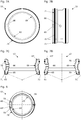
- FIG. 7 shows views of the inventive, here cylindrical illustrated change-valve seat 53. It shows the Fig. 7A a plan view of the change-valve seat 53. Specifically, here referred to a recessed into the outer surface of the change-valve seat 53 Richtnute 60, a vertically disposed, cylindrical sealing surface 69, a horizontally disposed conical sealing surface 63 and arranged on the change-valve seat 53 seal 70th ,
- the Fig. 7B shows a side view of the change-valve seat 53.
- Well visible here are the Richtnute 60, the alternating valve seat 53 piercing drainage opening 66 and the circumferential bearing surface 71, with which the change-valve seat 53 to rest on the support surface 59 of the hydrant component 56 '.
- the drainage opening 66 is disposed between two concentric annular seals 70. These seals 70 are shown here as partially inserted into corresponding grooves of the change-valve seat 53 O-rings.
- the Fig. 7C shows a vertical section of a first preferred embodiment of a change valve seat 53.
- Well visible here are again the Richtnute 60, the alternating valve seat 53 piercing drainage opening 66 and the peripheral bearing surface 71, with which the change-valve seat 53 on the support surface 59 of the hydrant component 56 'should rest.
- the drainage opening 66 is disposed between two concentric annular seals 70. These seals 70 are shown here as partially inserted into corresponding grooves of the change-valve seat 53 O-rings.
- the Fig. 7D shows a vertical section of a second preferred embodiment of a change-valve seat 53.
- the directional cam 61 the Change valve seat 53 piercing drainage hole 66 and the circumferential bearing surface 71, with which the change-valve seat 53 is to rest on the support surface 59 of the hydrant component 56 '.
- the drainage opening 66 is disposed between two concentric annular seals 70. These seals 70 are shown here as partially inserted into corresponding grooves of the change-valve seat 53 O-rings.
- This securing element 58 is designed as a radially movable and in a retaining groove 62 of a hydrant component 56 'engaging circlip and attached to at least one point on the change-valve seat 53 .
- This circlip has a certain similarity to a Seeger ring and, like such a two handle holes 72, engage in the extensions of a tool for insertion, removal or replacement of an inventive change-valve seat 53. With the engaging into the handle holes projections of the tool, the retaining ring and preferably thus the change-valve seat 53 is held and placed in the hydrant member 56 'and locked or unlocked and removed from the hydrant 56.
- Preferred materials for a replacement valve seat 53 include metals (such as brass or stainless steel) and plastics (such as high impact and / or high strength filled or fiber reinforced polyamides).
- metals such as brass or stainless steel
- plastics such as high impact and / or high strength filled or fiber reinforced polyamides.
Landscapes
- Health & Medical Sciences (AREA)
- Life Sciences & Earth Sciences (AREA)
- Engineering & Computer Science (AREA)
- Hydrology & Water Resources (AREA)
- Public Health (AREA)
- Water Supply & Treatment (AREA)
- Lift Valve (AREA)
Claims (18)
- Vanne principale de bouche d'incendie (51) pour une bouche d'incendie, la vanne principale de bouche d'incendie (51) comprenant un corps de vanne principale (52) et un siège de vanne principale (53), dans laquelle le corps de vanne principale (52) est réalisé de façon à pouvoir être amené, par le biais d'un dispositif d'entraînement (54), depuis au moins une position ouverte à au moins une position fermée et vice-versa, et dans laquelle le corps de vanne principale (52) sollicite le siège de vanne principale (53) dans la position fermée de sorte qu'un composant (56') de la bouche d'incendie (56) peut être rendu étanche par rapport à l'entrée de la bouche d'incendie (57) par la vanne principale de bouche d'incendie (51), dans laquelle le siège de vanne principale (53) est conçu comme un siège de vanne interchangeable (53) mobile en hauteur et pouvant être installé dans et retiré de la bouche d'incendie (56), dans laquelle le siège de vanne interchangeable (53) comprend un élément d'arrêt (58) qui est conçu pour maintenir le siège de vanne interchangeable (53) dans une position d'extrémité dans la bouche d'incendie (56), et dans laquelle le siège de vanne interchangeable (53) est réalisé annulaire et comprend deux joints d'étanchéité (70) annulaires concentriques, caractérisée en ce que le siège de vanne interchangeable (53) peut être installé et retiré librement dans le sens axial dans la bouche d'incendie (56), les deux joints d'étanchéité (70) annulaires concentriques dans la position d'extrémité du siège de vanne interchangeable (53) étant réalisés pour venir s'appliquer de façon étanche contre une surface intérieure (73) du composant (56') de la bouche d'incendie (56), le siège de vanne interchangeable (53) étant conçu pour venir solliciter une surface d'appui (59) sur le composant (56') de la bouche d'incendie (56) qui comprend aussi la surface intérieure (73), et l'élément d'arrêt (58) et le siège de vanne interchangeable (53) étant réalisés de façon à pouvoir être installés et retirés d'une bouche d'incendie, tous les composants (56') étant montés sur l'entrée de la bouche d'incendie (57).
- Vanne principale de bouche d'incendie (51) selon la revendication 1, caractérisée en ce que le siège de vanne interchangeable (53) et la surface intérieure (73) du composant (56') présentent une forme cylindrique ou une forme différente d'un cylindre.
- Vanne principale de bouche d'incendie (51) selon l'une des revendications 1 ou 2, caractérisée en ce que le siège de vanne interchangeable (53) comprend au moins une rainure de centrage (60) (60), dans laquelle, lorsque le siège de vanne interchangeable (53) est bien mis en place dans la bouche d'incendie (56), vient s'engager au moins une came de centrage (61) d'un composant (65') de la bouche d'incendie (56) de taille et position correspondantes.
- Vanne principale de bouche d'incendie (51) selon l'une des revendications 1 ou 2, caractérisée en ce que le siège de vanne interchangeable (53) comprend au moins une came de centrage (61) qui, lorsque le siège de vanne interchangeable (53) est bien mis en place dans la bouche d'incendie (56), s'engage dans au moins une rainure de centrage (60) d'un composant (65') de la bouche d'incendie (56) de taille et position correspondantes.
- Vanne principale de bouche d'incendie (51) selon l'une des revendications précédentes, caractérisée en ce que le composant (56') de la bouche d'incendie (56) avec la surface d'appui (59) sollicitée, avec la surface intérieure d'étanchéité (73) et avec la rainure de centrage (60) ou avec la came de centrage (61), est choisi à partir d'un groupe comprenant la conduite montante (55), une bague intermédiaire, l'entrée de la bouche d'incendie (57) et un boîtier de vanne agencé séparé entre la conduite montante (55) et l'entrée de la bouche d'incendie (57).
- Vanne principale de bouche d'incendie (51) selon l'une des revendications 2 à 5, caractérisée en ce que la forme différente d'un cylindre du siège de vanne interchangeable (53) annulaire et de la surface intérieure (73) du composant (56') présente une section transversale comparable à un polygone, ovale ou elliptique.
- Vanne principale de bouche d'incendie (51) selon la revendication 6, caractérisée en ce que la section transversale semblable à un polygone du siège de vanne interchangeable annulaire (53) et de la surface intérieure (73) du composant (56') se rapproche d'un hexagone ou d'un octogone.
- Vanne principale de bouche d'incendie (51) selon l'une des revendications 1 à 7, caractérisée en ce que l'élément d'arrêt (58) est réalisé sous la forme d'une bague de retenue élastique mobile radialement et venant s'engager dans une rainure de retenue (62) d'un composant de la bouche d'incendie (56').
- Vanne principale de bouche d'incendie (51) selon la revendication 8, caractérisée en ce que l'élément d'arrêt (58) réalisé sous la forme d'une bague de retenue élastique, est fixé sur le siège de vanne interchangeable (53).
- Vanne principale de bouche d'incendie (51) selon l'une des revendications 1 à 7, caractérisée en ce que l'élément d'arrêt (58) est réalisé sous la forme d'une bague de retenue pouvant être insérée axialement dans un filet d'un composant de bouche d'incendie (56').
- Vanne principale de bouche d'incendie (51) selon l'une des revendications 1 à 7, caractérisée en ce que l'élément d'arrêt (58) est réalisé sous la forme d'une bague de retenue pouvant être insérée axialement dans une baïonnette d'un composant de la bouche d'incendie (56').
- Vanne principale de bouche d'incendie (51) selon l'une des revendications 8 à 11, caractérisée en ce que l'élément d'arrêt (58) et le siège de vanne interchangeable (53) sont réalisés de façon à pouvoir être montés et démontés à l'aide d'un outil sous haute pression ou sous pression de service.
- Vanne principale de bouche d'incendie (51) selon l'une des revendications précédentes, caractérisée en ce que le siège de vanne interchangeable (53) comprend au moins une surface d'étanchéité annulaire pour un corps de vanne principale (52), cette au moins une surface d'étanchéité étant choisie à partir du groupe composé de surfaces d'étanchéité coniques (63), de surfaces d'étanchéité plates (63') et de surfaces d'étanchéité cylindriques (69).
- Vanne principale de bouche d'incendie (51) selon l'une des revendications précédentes, dans laquelle la bouche d'incendie (56) est équipée d'une fermeture double, qui comprend une vanne principale de bouche d'incendie (51) et un organe de fermeture supplémentaire (64), caractérisée en ce que le siège de vanne interchangeable (53) est supérieur dans ses dimensions extérieures aux dimensions extérieures de l'organe de fermeture supplémentaire (64), cet organe de fermeture supplémentaire (64) pouvant ainsi être retiré de la bouche d'incendie (56) après le retrait du siège de vanne interchangeable (53) mobile en hauteur sans démontage de la conduite montante (55).
- Vanne principale de bouche d'incendie (51) selon la revendication 14, caractérisée en ce que l'organe de fermeture supplémentaire (64) est réalisé sphérique et en ce que le siège de vanne interchangeable (53) comprend une surface d'étanchéité sphérique (65) pour l'organe de fermeture supplémentaire (64).
- Vanne principale de bouche d'incendie (51) selon l'une des revendications précédentes, caractérisée en ce que le siège de vanne interchangeable (53) présente au moins une ouverture de purge (66) qui est conçue pour diriger l'eau vers une protection de purge (67) agencée à proximité du siège de vanne interchangeable (53).
- Bouche d'incendie (56) caractérisée en ce qu'elle comprend une vanne principale de bouche d'incendie (51) avec un siège de vanne interchangeable (53) selon l'une des revendications précédentes.
- Bouche d'incendie (56) selon la revendication 17, caractérisée en ce qu'elle comprend à proximité du siège de vanne interchangeable (53) une vanne de purge (68) réalisée sous la forme d'un clapet antiretour qui se ferme dès que la bouche d'incendie (56) est sous pression élevée ou sous pression de service.
Priority Applications (1)
| Application Number | Priority Date | Filing Date | Title |
|---|---|---|---|
| SI201431335T SI2781663T1 (sl) | 2013-03-19 | 2014-03-11 | Glavni ventil hidranta z nadomestljivim sedežem ventila |
Applications Claiming Priority (1)
| Application Number | Priority Date | Filing Date | Title |
|---|---|---|---|
| CH00625/13A CH707819A1 (de) | 2013-03-19 | 2013-03-19 | Hydrantenhauptventil mit Wechsel-Ventilsitz. |
Publications (2)
| Publication Number | Publication Date |
|---|---|
| EP2781663A1 EP2781663A1 (fr) | 2014-09-24 |
| EP2781663B1 true EP2781663B1 (fr) | 2019-06-05 |
Family
ID=48740765
Family Applications (1)
| Application Number | Title | Priority Date | Filing Date |
|---|---|---|---|
| EP14158881.4A Active EP2781663B1 (fr) | 2013-03-19 | 2014-03-11 | Vanne principale de tricoise avec siège de vanne à inversion |
Country Status (3)
| Country | Link |
|---|---|
| EP (1) | EP2781663B1 (fr) |
| CH (1) | CH707819A1 (fr) |
| SI (1) | SI2781663T1 (fr) |
Families Citing this family (2)
| Publication number | Priority date | Publication date | Assignee | Title |
|---|---|---|---|---|
| UA123106C2 (uk) * | 2016-02-16 | 2021-02-17 | Фонролл Інфратек (Інвестмент) Аг | Дренаж гідранта |
| EP4341499B1 (fr) | 2021-05-20 | 2025-07-02 | AVK Holding A/S | Borne d'eau comprenant un logement de borne d'eau et un siege de soupape et procede de montage d'un siege de soupape dans une borne d'eau |
Family Cites Families (9)
| Publication number | Priority date | Publication date | Assignee | Title |
|---|---|---|---|---|
| GB191026561A (en) | 1910-11-15 | 1911-08-24 | Herbert Merrill Lofton | Improvements in and relating to Valve Mechanism for Fire Hydrants. |
| US3980096A (en) * | 1975-07-29 | 1976-09-14 | Mueller Co. | Fire hydrant |
| CH675139A5 (en) | 1987-10-12 | 1990-08-31 | Von Roll Ag | Hydrant with frost protection device - with shut-off valve which ensures that stand-pipe is drained before cover can be replaced |
| CH675151A5 (en) * | 1987-10-16 | 1990-08-31 | Von Roll Ag | Drain for hydrant interior - consists of main part and non-return valve with housing and spring, and sleeve shaped outer housing |
| US4763686A (en) * | 1988-01-22 | 1988-08-16 | Halliburton Company | Hydrant and components thereof |
| CH693642A5 (de) | 1999-06-15 | 2003-11-28 | Von Roll Infranet Sa | Rohrverbindung und eine solche Rohrverbindung aufweisender, höhenverstellbarer Hydrant. |
| CH694969A5 (de) | 1999-10-14 | 2005-10-14 | Von Roll Infranet Sa | Dichtung für eine Zusatzabsperrung und eine entsprechende Zusatzabsperrung für einen Hydranten, sowie einen entsprechenden Hydranten. |
| CH701570B1 (de) | 2006-12-05 | 2011-02-15 | Hawle Armaturen Ag | Austauschelemente zum Instandsetzen undichter Ventile in Hydranten. |
| CH701582B1 (de) * | 2007-11-28 | 2011-02-15 | Vonroll Infratec Invest Ag | Fluidleitungsschieber-Spindellagerung mit Bajonettverschluss. |
-
2013
- 2013-03-19 CH CH00625/13A patent/CH707819A1/de not_active Application Discontinuation
-
2014
- 2014-03-11 EP EP14158881.4A patent/EP2781663B1/fr active Active
- 2014-03-11 SI SI201431335T patent/SI2781663T1/sl unknown
Non-Patent Citations (1)
| Title |
|---|
| None * |
Also Published As
| Publication number | Publication date |
|---|---|
| CH707819A1 (de) | 2014-09-30 |
| SI2781663T1 (sl) | 2019-11-29 |
| EP2781663A1 (fr) | 2014-09-24 |
Similar Documents
| Publication | Publication Date | Title |
|---|---|---|
| DE10028655B4 (de) | Rohrverbindung und eine solche Rohrverbindung aufweisende, höhenverstellbare Hydranten | |
| EP2781663B1 (fr) | Vanne principale de tricoise avec siège de vanne à inversion | |
| DE102007041753A1 (de) | Vorrichtung zur Drosselung des freien Querschnittes einer Dampfleitung oder dergleichen | |
| EP3470586B1 (fr) | Obturateur pour utilisation dans une bouche d'incendie, bouche d'incendie et siège de soupape principal | |
| DE3435778A1 (de) | Hydrant, insbesondere unterflurhydrant | |
| DE1500166A1 (de) | Ventil mit drehbarem Kueken | |
| EP3688238A1 (fr) | Dispositif anti-reflux et séparateur de système en particulier pour le domaine de la lutte contre les incendies | |
| EP4067710B1 (fr) | Raccord de tuyau pour une bouche d'incendie et bouche d'incendie | |
| AT413237B (de) | Absperrschieber für druckrohrleitungen | |
| DE102012105311A1 (de) | Bodenablauf | |
| EP2679869B1 (fr) | Soupape principale pour une prise d'eau | |
| EP3633111B1 (fr) | Raccord pour tuyau flexible pour une bouche d'eau | |
| DE102022132044B3 (de) | Einbaugarnitur zur Betätigung einer Unterflurarmatur | |
| EP2963195B1 (fr) | Reniflard | |
| WO1995019518A1 (fr) | Dispositif de guidage pour tige fixe de vanne | |
| EP4001522B1 (fr) | Robinet à encastrer à ancrage au sol | |
| DE202012101123U1 (de) | Rohrtrenneranordnung | |
| DE20116280U1 (de) | Ventiloberteil für Armaturen | |
| DE19835713A1 (de) | Armatur-Wechseleinheit | |
| CH707858B1 (de) | Höherverstellbarer Hydrant. | |
| DE4243756A1 (de) | Hydrant | |
| CH701570B1 (de) | Austauschelemente zum Instandsetzen undichter Ventile in Hydranten. | |
| DE29716914U1 (de) | Sicherungseinrichtung mit Rohrunterbrecher und Rohrbelüfter | |
| CH697899B1 (de) | Ventil. | |
| DE20207642U1 (de) | Hochdruckfester Verbindungsverschluss |
Legal Events
| Date | Code | Title | Description |
|---|---|---|---|
| PUAI | Public reference made under article 153(3) epc to a published international application that has entered the european phase |
Free format text: ORIGINAL CODE: 0009012 |
|
| 17P | Request for examination filed |
Effective date: 20140311 |
|
| AK | Designated contracting states |
Kind code of ref document: A1 Designated state(s): AL AT BE BG CH CY CZ DE DK EE ES FI FR GB GR HR HU IE IS IT LI LT LU LV MC MK MT NL NO PL PT RO RS SE SI SK SM TR |
|
| AX | Request for extension of the european patent |
Extension state: BA ME |
|
| R17P | Request for examination filed (corrected) |
Effective date: 20150318 |
|
| RBV | Designated contracting states (corrected) |
Designated state(s): AL AT BE BG CH CY CZ DE DK EE ES FI FR GB GR HR HU IE IS IT LI LT LU LV MC MK MT NL NO PL PT RO RS SE SI SK SM TR |
|
| GRAP | Despatch of communication of intention to grant a patent |
Free format text: ORIGINAL CODE: EPIDOSNIGR1 |
|
| STAA | Information on the status of an ep patent application or granted ep patent |
Free format text: STATUS: GRANT OF PATENT IS INTENDED |
|
| INTG | Intention to grant announced |
Effective date: 20181030 |
|
| GRAS | Grant fee paid |
Free format text: ORIGINAL CODE: EPIDOSNIGR3 |
|
| GRAA | (expected) grant |
Free format text: ORIGINAL CODE: 0009210 |
|
| STAA | Information on the status of an ep patent application or granted ep patent |
Free format text: STATUS: THE PATENT HAS BEEN GRANTED |
|
| AK | Designated contracting states |
Kind code of ref document: B1 Designated state(s): AL AT BE BG CH CY CZ DE DK EE ES FI FR GB GR HR HU IE IS IT LI LT LU LV MC MK MT NL NO PL PT RO RS SE SI SK SM TR |
|
| REG | Reference to a national code |
Ref country code: GB Ref legal event code: FG4D Free format text: NOT ENGLISH |
|
| REG | Reference to a national code |
Ref country code: CH Ref legal event code: EP |
|
| REG | Reference to a national code |
Ref country code: AT Ref legal event code: REF Ref document number: 1140107 Country of ref document: AT Kind code of ref document: T Effective date: 20190615 |
|
| REG | Reference to a national code |
Ref country code: IE Ref legal event code: FG4D Free format text: LANGUAGE OF EP DOCUMENT: GERMAN |
|
| REG | Reference to a national code |
Ref country code: DE Ref legal event code: R096 Ref document number: 502014011831 Country of ref document: DE |
|
| REG | Reference to a national code |
Ref country code: NL Ref legal event code: FP |
|
| REG | Reference to a national code |
Ref country code: SE Ref legal event code: TRGR |
|
| REG | Reference to a national code |
Ref country code: CH Ref legal event code: NV Representative=s name: OK PAT AG PATENTE MARKEN LIZENZEN, CH |
|
| REG | Reference to a national code |
Ref country code: LT Ref legal event code: MG4D |
|
| PG25 | Lapsed in a contracting state [announced via postgrant information from national office to epo] |
Ref country code: AL Free format text: LAPSE BECAUSE OF FAILURE TO SUBMIT A TRANSLATION OF THE DESCRIPTION OR TO PAY THE FEE WITHIN THE PRESCRIBED TIME-LIMIT Effective date: 20190605 Ref country code: ES Free format text: LAPSE BECAUSE OF FAILURE TO SUBMIT A TRANSLATION OF THE DESCRIPTION OR TO PAY THE FEE WITHIN THE PRESCRIBED TIME-LIMIT Effective date: 20190605 Ref country code: FI Free format text: LAPSE BECAUSE OF FAILURE TO SUBMIT A TRANSLATION OF THE DESCRIPTION OR TO PAY THE FEE WITHIN THE PRESCRIBED TIME-LIMIT Effective date: 20190605 Ref country code: LT Free format text: LAPSE BECAUSE OF FAILURE TO SUBMIT A TRANSLATION OF THE DESCRIPTION OR TO PAY THE FEE WITHIN THE PRESCRIBED TIME-LIMIT Effective date: 20190605 Ref country code: HR Free format text: LAPSE BECAUSE OF FAILURE TO SUBMIT A TRANSLATION OF THE DESCRIPTION OR TO PAY THE FEE WITHIN THE PRESCRIBED TIME-LIMIT Effective date: 20190605 |
|
| REG | Reference to a national code |
Ref country code: NO Ref legal event code: T2 Effective date: 20190605 |
|
| PG25 | Lapsed in a contracting state [announced via postgrant information from national office to epo] |
Ref country code: LV Free format text: LAPSE BECAUSE OF FAILURE TO SUBMIT A TRANSLATION OF THE DESCRIPTION OR TO PAY THE FEE WITHIN THE PRESCRIBED TIME-LIMIT Effective date: 20190605 Ref country code: GR Free format text: LAPSE BECAUSE OF FAILURE TO SUBMIT A TRANSLATION OF THE DESCRIPTION OR TO PAY THE FEE WITHIN THE PRESCRIBED TIME-LIMIT Effective date: 20190906 Ref country code: BG Free format text: LAPSE BECAUSE OF FAILURE TO SUBMIT A TRANSLATION OF THE DESCRIPTION OR TO PAY THE FEE WITHIN THE PRESCRIBED TIME-LIMIT Effective date: 20190905 Ref country code: RS Free format text: LAPSE BECAUSE OF FAILURE TO SUBMIT A TRANSLATION OF THE DESCRIPTION OR TO PAY THE FEE WITHIN THE PRESCRIBED TIME-LIMIT Effective date: 20190605 |
|
| PG25 | Lapsed in a contracting state [announced via postgrant information from national office to epo] |
Ref country code: PT Free format text: LAPSE BECAUSE OF FAILURE TO SUBMIT A TRANSLATION OF THE DESCRIPTION OR TO PAY THE FEE WITHIN THE PRESCRIBED TIME-LIMIT Effective date: 20191007 Ref country code: RO Free format text: LAPSE BECAUSE OF FAILURE TO SUBMIT A TRANSLATION OF THE DESCRIPTION OR TO PAY THE FEE WITHIN THE PRESCRIBED TIME-LIMIT Effective date: 20190605 Ref country code: CZ Free format text: LAPSE BECAUSE OF FAILURE TO SUBMIT A TRANSLATION OF THE DESCRIPTION OR TO PAY THE FEE WITHIN THE PRESCRIBED TIME-LIMIT Effective date: 20190605 Ref country code: SK Free format text: LAPSE BECAUSE OF FAILURE TO SUBMIT A TRANSLATION OF THE DESCRIPTION OR TO PAY THE FEE WITHIN THE PRESCRIBED TIME-LIMIT Effective date: 20190605 Ref country code: EE Free format text: LAPSE BECAUSE OF FAILURE TO SUBMIT A TRANSLATION OF THE DESCRIPTION OR TO PAY THE FEE WITHIN THE PRESCRIBED TIME-LIMIT Effective date: 20190605 |
|
| PG25 | Lapsed in a contracting state [announced via postgrant information from national office to epo] |
Ref country code: IT Free format text: LAPSE BECAUSE OF FAILURE TO SUBMIT A TRANSLATION OF THE DESCRIPTION OR TO PAY THE FEE WITHIN THE PRESCRIBED TIME-LIMIT Effective date: 20190605 Ref country code: IS Free format text: LAPSE BECAUSE OF FAILURE TO SUBMIT A TRANSLATION OF THE DESCRIPTION OR TO PAY THE FEE WITHIN THE PRESCRIBED TIME-LIMIT Effective date: 20191005 Ref country code: SM Free format text: LAPSE BECAUSE OF FAILURE TO SUBMIT A TRANSLATION OF THE DESCRIPTION OR TO PAY THE FEE WITHIN THE PRESCRIBED TIME-LIMIT Effective date: 20190605 |
|
| REG | Reference to a national code |
Ref country code: DE Ref legal event code: R097 Ref document number: 502014011831 Country of ref document: DE |
|
| PG25 | Lapsed in a contracting state [announced via postgrant information from national office to epo] |
Ref country code: TR Free format text: LAPSE BECAUSE OF FAILURE TO SUBMIT A TRANSLATION OF THE DESCRIPTION OR TO PAY THE FEE WITHIN THE PRESCRIBED TIME-LIMIT Effective date: 20190605 |
|
| PLBE | No opposition filed within time limit |
Free format text: ORIGINAL CODE: 0009261 |
|
| STAA | Information on the status of an ep patent application or granted ep patent |
Free format text: STATUS: NO OPPOSITION FILED WITHIN TIME LIMIT |
|
| PG25 | Lapsed in a contracting state [announced via postgrant information from national office to epo] |
Ref country code: DK Free format text: LAPSE BECAUSE OF FAILURE TO SUBMIT A TRANSLATION OF THE DESCRIPTION OR TO PAY THE FEE WITHIN THE PRESCRIBED TIME-LIMIT Effective date: 20190605 Ref country code: PL Free format text: LAPSE BECAUSE OF FAILURE TO SUBMIT A TRANSLATION OF THE DESCRIPTION OR TO PAY THE FEE WITHIN THE PRESCRIBED TIME-LIMIT Effective date: 20190605 |
|
| 26N | No opposition filed |
Effective date: 20200306 |
|
| PG25 | Lapsed in a contracting state [announced via postgrant information from national office to epo] |
Ref country code: MC Free format text: LAPSE BECAUSE OF FAILURE TO SUBMIT A TRANSLATION OF THE DESCRIPTION OR TO PAY THE FEE WITHIN THE PRESCRIBED TIME-LIMIT Effective date: 20190605 |
|
| REG | Reference to a national code |
Ref country code: CH Ref legal event code: PFUS Owner name: VONROLL INFRATEC (INVESTMENT) AG, CH Free format text: FORMER OWNER: VONROLL INFRATEC (INVESTMENT) AG, CH |
|
| PG25 | Lapsed in a contracting state [announced via postgrant information from national office to epo] |
Ref country code: IE Free format text: LAPSE BECAUSE OF NON-PAYMENT OF DUE FEES Effective date: 20200311 |
|
| PG25 | Lapsed in a contracting state [announced via postgrant information from national office to epo] |
Ref country code: MT Free format text: LAPSE BECAUSE OF FAILURE TO SUBMIT A TRANSLATION OF THE DESCRIPTION OR TO PAY THE FEE WITHIN THE PRESCRIBED TIME-LIMIT Effective date: 20190605 Ref country code: CY Free format text: LAPSE BECAUSE OF FAILURE TO SUBMIT A TRANSLATION OF THE DESCRIPTION OR TO PAY THE FEE WITHIN THE PRESCRIBED TIME-LIMIT Effective date: 20190605 |
|
| PG25 | Lapsed in a contracting state [announced via postgrant information from national office to epo] |
Ref country code: MK Free format text: LAPSE BECAUSE OF FAILURE TO SUBMIT A TRANSLATION OF THE DESCRIPTION OR TO PAY THE FEE WITHIN THE PRESCRIBED TIME-LIMIT Effective date: 20190605 |
|
| P01 | Opt-out of the competence of the unified patent court (upc) registered |
Effective date: 20230526 |
|
| PGFP | Annual fee paid to national office [announced via postgrant information from national office to epo] |
Ref country code: SI Payment date: 20250225 Year of fee payment: 12 |
|
| PGFP | Annual fee paid to national office [announced via postgrant information from national office to epo] |
Ref country code: CH Payment date: 20250401 Year of fee payment: 12 |
|
| PGFP | Annual fee paid to national office [announced via postgrant information from national office to epo] |
Ref country code: NL Payment date: 20260227 Year of fee payment: 13 Ref country code: LU Payment date: 20260227 Year of fee payment: 13 |
|
| REG | Reference to a national code |
Ref country code: CH Ref legal event code: U11 Free format text: ST27 STATUS EVENT CODE: U-0-0-U10-U11 (AS PROVIDED BY THE NATIONAL OFFICE) Effective date: 20260401 |
|
| PGFP | Annual fee paid to national office [announced via postgrant information from national office to epo] |
Ref country code: SE Payment date: 20260227 Year of fee payment: 13 |
|
| PGFP | Annual fee paid to national office [announced via postgrant information from national office to epo] |
Ref country code: GB Payment date: 20260216 Year of fee payment: 13 |
|
| PGFP | Annual fee paid to national office [announced via postgrant information from national office to epo] |
Ref country code: DE Payment date: 20260218 Year of fee payment: 13 Ref country code: NO Payment date: 20260310 Year of fee payment: 13 |
|
| PGFP | Annual fee paid to national office [announced via postgrant information from national office to epo] |
Ref country code: AT Payment date: 20260225 Year of fee payment: 13 |
|
| PGFP | Annual fee paid to national office [announced via postgrant information from national office to epo] |
Ref country code: BE Payment date: 20260216 Year of fee payment: 13 |
|
| PGFP | Annual fee paid to national office [announced via postgrant information from national office to epo] |
Ref country code: FR Payment date: 20260223 Year of fee payment: 13 |