EP2779899B1 - Vorrichtung zur längenmessung - Google Patents
Vorrichtung zur längenmessung Download PDFInfo
- Publication number
- EP2779899B1 EP2779899B1 EP12798137.1A EP12798137A EP2779899B1 EP 2779899 B1 EP2779899 B1 EP 2779899B1 EP 12798137 A EP12798137 A EP 12798137A EP 2779899 B1 EP2779899 B1 EP 2779899B1
- Authority
- EP
- European Patent Office
- Prior art keywords
- sensor
- person
- emitter
- measured
- coupled
- Prior art date
- Legal status (The legal status is an assumption and is not a legal conclusion. Google has not performed a legal analysis and makes no representation as to the accuracy of the status listed.)
- Active
Links
Images




Classifications
-
- A—HUMAN NECESSITIES
- A61—MEDICAL OR VETERINARY SCIENCE; HYGIENE
- A61B—DIAGNOSIS; SURGERY; IDENTIFICATION
- A61B5/00—Measuring for diagnostic purposes; Identification of persons
- A61B5/103—Measuring devices for testing the shape, pattern, colour, size or movement of the body or parts thereof, for diagnostic purposes
- A61B5/107—Measuring physical dimensions, e.g. size of the entire body or parts thereof
- A61B5/1072—Measuring physical dimensions, e.g. size of the entire body or parts thereof measuring distances on the body, e.g. measuring length, height or thickness
-
- A—HUMAN NECESSITIES
- A61—MEDICAL OR VETERINARY SCIENCE; HYGIENE
- A61B—DIAGNOSIS; SURGERY; IDENTIFICATION
- A61B5/00—Measuring for diagnostic purposes; Identification of persons
- A61B5/103—Measuring devices for testing the shape, pattern, colour, size or movement of the body or parts thereof, for diagnostic purposes
- A61B5/107—Measuring physical dimensions, e.g. size of the entire body or parts thereof
- A61B5/1079—Measuring physical dimensions, e.g. size of the entire body or parts thereof using optical or photographic means
Definitions
- the invention relates to a device for measuring the body length of a person, in which at least one emitter for emitting a primary signal and at least one sensor for detecting a measurement signal are arranged in the area of an inner boundary of a building, and in which both the emitter and the sensor have a control device are coupled, which is coupled to a display device.
- length measuring rods are often used, which are for example self-standing with a foot part or are mounted on a wall.
- the person to be measured typically stands with their back against this length measuring rod and an exact head positioning is specified by a so-called head stop.
- head stop is specified by a so-called head stop.
- a device for measuring the body length of a person is already known. The measurement is carried out using an emitter arranged in a building room and a sensor. Similar devices for measuring the body length of a person are also used in the WO 2011/127578 A1 , of the US 2005/171451 A1 , of the US 2010/298708 A1 and the DE 20 2010 016 423 U1 described.
- a device for measuring the body length of a person is already known.
- An emitter and a sensor are used.
- the emitter is designed as a sound generator and the sensor is suitable for receiving a reflected sound.
- the object of the present invention is to construct a device of the type mentioned in the introduction in such a way that a contactless measurement of the body length is supported with ease of use.
- the term sensor is to be understood comprehensively in connection with the present invention.
- the sensor can consist of one or more transmitters and one or more receivers. It is also possible to implement the function of the transmitter and the receiver in the area of the sensor using a single component.
- both the emitter and the sensor By arranging both the emitter and the sensor in the area of the inner boundary of a building space, a stationary device is provided which supports very user-friendly use.
- both the Both the emitter and the sensor are arranged outside of areas that are typically subject to contamination.
- the device for the contactless measurement of the body length is therefore also particularly suitable for use in the area of medical practices or hospitals, where particularly high demands are placed on cleanliness.
- the device additionally has a scale for recording a weight of the person to be measured.
- control device be designed to evaluate a reference measurement that takes into account the distance between the sensor and a standing surface of the person to be measured.
- the senor is arranged in the area of a ceiling of the room.
- the senor is arranged in the area of a wall of the room.
- a projector be used to project a stand marking for the person to be measured.
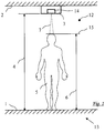
- an interior space (12) of a building (13) is at least partially delimited by a floor (1) and a ceiling (2).
- an emitter (14) and at least one sensor (3) are arranged in the area of the ceiling (2).
- a distance (4) between the sensor (3) and the floor (1) must be taken into account.
- An upper boundary (15) of a head of the person to be measured (5) is at a distance from the floor (1) which corresponds to the body length (6) to be determined.
- Fig. 1 and Fig. 5 also exemplify a typical detection area (7) of the sensor (3).
- Fig. 2 shows one opposite Fig. 1
- a spacer (8) as a holder for the sensor (3).
- the spacer (8) can be used, for example, at room heights which would lead to too great a distance between the sensor (3) and the person to be measured (5).
- the spacer (8) can also generally be designed as a holder for the sensor (3) and / or the emitter (14).
- Fig. 3 shows a further embodiment in which the sensor (3) is attached in the area of a wall (9) of the building (13).
- the exemplary embodiment shown shows the attachment of the sensor (3) using a wall bracket (10).
- a wall bracket (10) According to the embodiment in Fig. 3 takes place similarly to the embodiments in Fig. 1 and 2 a measurement of the body length with a detection direction in the vertical direction downwards.
- the wall bracket (10) is therefore essentially used for suitable positioning of the sensor (3).
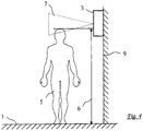
- the detection area (7) starting from the sensor (3) is aligned with a horizontal component. There is thus a lateral measurement of the body length of the person to be measured (5).
- a projector (17) is used, which projects a marking (11) in the area of the floor (1).
- the marking defines an optimal position for the person to be measured (5).
- a projector for the marking can be arranged in the vicinity of the sensor (3), for example.
- the marking it is also not possible according to the invention for the marking to be able to be projected from the side.
- a projection from the side prevents the marking from being shaded by the person to be measured when stepping on the marking. If the projector is arranged in the area of the sensor (3), the projector can be integrated into the housing of the sensor (3).
- Fig. 6 schematically illustrates a coupling of the emitter (14) and the sensor (3) to a control device (18).
- the coupling is preferably carried out in a contactless manner, for example via a radio link or an optical coupling.
- the control device (18) is also coupled to a display device (19).
- the coupling is preferably contactless.
- the display of a computer for example, can be used as the display device (19).
- portable devices that can be held in the hand, for example corresponding to a cell phone or a remote control, is also envisaged.
- the emitter (14) can emit different primary signals, for example ultrasound, radar waves or a laser beam. It is also possible to design the emitter (14) only as a lighting device and to use a camera as a sensor (3) which is preferably coupled to a control device which is designed to carry out pattern recognition.
- a special projector (17) to generate a marking (11) in the area of the floor (1), for example using a red laser beam, it is also possible to glue the marking (11), for example, to the floor (1) or to be produced here permanently in a different way.
- the measuring device can be used in rooms of different heights and the control device (18) can take into account the length reference determined in this way as a correction value. It is also possible, for example, to take into account a drift of the sensor (3) due to temperature changes or due to changes in air humidity using one or more reference measurements. These correction values can also be taken into account in the exact determination of the respective body length of the person to be measured (5).
- Triangulation can be used, for example, for lateral length measurements.
- the device components used can be supplied with energy via the existing power grid or via a battery or photovoltaic system. Directed wireless energy transfers are also applicable.
- the measuring device according to the invention reports special installation devices and a space required for this purpose. Furthermore, it is also not necessary to clean or disinfect the measuring device since there is no body contact with the user.
- the measuring device When the measuring device is combined with a scale, it is also possible in particular to adapt the installation location of the emitter (14) and / or the sensor (3) to the already given positioning of the scale in the case of already installed scales.
Landscapes
- Health & Medical Sciences (AREA)
- Life Sciences & Earth Sciences (AREA)
- Medical Informatics (AREA)
- Molecular Biology (AREA)
- Oral & Maxillofacial Surgery (AREA)
- Biophysics (AREA)
- Pathology (AREA)
- Engineering & Computer Science (AREA)
- Biomedical Technology (AREA)
- Heart & Thoracic Surgery (AREA)
- Dentistry (AREA)
- Physics & Mathematics (AREA)
- Surgery (AREA)
- Animal Behavior & Ethology (AREA)
- General Health & Medical Sciences (AREA)
- Public Health (AREA)
- Veterinary Medicine (AREA)
- Length Measuring Devices With Unspecified Measuring Means (AREA)
- Measurement Of The Respiration, Hearing Ability, Form, And Blood Characteristics Of Living Organisms (AREA)
- Optical Radar Systems And Details Thereof (AREA)
- Length Measuring Devices By Optical Means (AREA)
Description
- Die Erfindung betrifft eine Vorrichtung zur Messung der Körperlänge einer Person, bei der im Bereich einer Innenbegrenzung eines Gebäuderaumes mindestens ein Emitter zur Abgabe eines Primärsignales und mindestens ein Sensor zur Erfassung eines Messsignals angeordnet sind und bei der sowohl der Emitter als auch der Sensor mit einer Steuereinrichtung gekoppelt sind, die mit einer Anzeigeeinrichtung gekoppelt ist.
- Zur Messung der Körperlänge einer Person werden häufig sogenannte Längenmessstäbe eingesetzt, die beispielsweise selbststehend mit einem Fußteil versehen sind oder an einer Wand montiert werden. Die zu vermessende Person stellt sich typischerweise mit dem Rücken gegen diesen Längenmessstab und eine exakte Kopfpositionierung wird durch einen sogenannten Kopfanschlag vorgegeben. Die zu vermessende Person kommt hierdurch in einen Körperkontakt mit der Messeinrichtung, was häufig als unangenehm oder zumindest unerwünscht empfunden wird.
- Bekannt sind ebenfalls bereits berührungslose Längen- oder Abstandsmesseinrichtungen, die im Bereich des Fußbodens eines Raumes aufgestellt werden. Hierdurch können Entfernungen, beispielsweise über eine Ultraschall-Messung, ermittelt werden.
- Aus der
US 2010/312143 A1 ist bereits eine Vorrichtung zur Messung der Körperlänge einer Person bekannt. Die Messung erfolgt unter Verwendung eines in einem Gebäuderaum angeordneten Emitters sowie eines Sensors. Vergleichbare Vorrichtungen zur Messung der Körperlänge einer Person werden auch in derWO 2011/127578 A1 , derUS 2005/171451 A1 , derUS 2010/298708 A1 und derDE 20 2010 016 423 U1 beschrieben. - Aus der
WO 2011/127578 A1 ist bereits eine Vorrichtung zur Messung der Körperlänge einer Person bekannt Es werden ein Emitter und ein Sensor verwendet. Der Emitter ist als ein Schallgeber ausgebildet und der Sensor ist zum Empfang eines reflektierten Schalls geeignet. - Aufgabe der vorliegenden Erfindung ist es, eine Vorrichtung der einleitend genannten Art derart zu konstruieren, dass eine berührungslose Messung der Körperlänge bei einfacher Bedienbarkeit unterstützt wird.
- Diese Aufgabe wird erfindungsgemäß durch die Merkmale von Patentanspruch Nr. 1 gelöst.
- Der Begriff des Sensors ist im Zusammenhang mit der vorliegenden Erfindung umfassend zu verstehen. Insbesondere ist daran gedacht, dass der Sensor aus einem oder mehreren Sendern sowie aus einem oder mehreren Empfängern bestehen kann. Ebenfalls ist es möglich, die Funktion des Senders und des Empfängers im Bereich des Sensors durch eine einzige Komponente zu realisieren.
- Durch die Anordnung sowohl des Emitters als auch des Sensors im Bereich der Innenbegrenzung eines Gebäuderaumes wird eine stationäre Einrichtung bereitgestellt, die eine sehr bedienungsfreundliche Benutzung unterstützt. Insbesondere sind sowohl der Emitter als auch der Sensor außerhalb von Bereichen angeordnet, die typischerweise Verschmutzungen unterliegen. Die Vorrichtung zur berührungslosen Messung der Körperlänge eignet sich somit insbesondere auch für Verwendungen im Bereich von Arztpraxen oder von Krankenhäusern, wo besonders hohe Anforderungen an die Sauberkeit gestellt werden.
- Zusätzliche Informationen über die zu vermessende Person können dadurch bereitgestellt werden, dass die Vorrichtung zusätzlich eine Waage zur Erfassung eines Gewichtes der zu vermessenden Person aufweist.
- Zur Anpassung an räumliche Gegebenheiten wird vorgeschlagen, dass die Steuereinrichtung zur Auswertung einer Referenzmessung ausgebildet ist, die den Abstand des Sensors zu einer Standfläche der zu vermessenden Person berücksichtigt.
- Gemäß einer typischen Ausführungsform ist vorgesehen, dass der Sensor im Bereich einer Decke des Raumes angeordnet ist.
- Gemäß einer anderen Ausführungsform ist es auch möglich, dass der Sensor im Bereich einer Wand des Raumes angeordnet ist.
- Eine individuelle Anpassung an konkret vorliegende räumliche Gegebenheiten wird dadurch unterstützt, dass der Sensor unter Verwendung einer Halterung installiert ist.
- Zur Unterstützung möglichst genauer Messergebnisse wird vorgeschlagen, dass ein Projektor zur Projektion einer Standmarkierung für die zu vermessende Person verwendet ist.
- In den Zeichnungen sind Ausführungsbeispiele der Erfindung schematisch dargestellt. Es zeigen:
- Fig. 1
- Eine schematische Darstellung einer Seitenansicht einer im Bereich einer Gebäudedecke angeordneten Messeinrichtung sowie einer zu vermessenden Person,
- Fig. 2
- die Anordnung gemäß
Fig. 2 bei zusätzlicher Verwendung eines Gestells für die Messeinrichtung, - Fig. 3
- eine schematische Darstellung einer weiteren Ausführungsform, bei der die Messeinrichtung im Bereich einer Wand des Gebäudes montiert ist,
- Fig. 4
- ein weiteres Beispiel mit einer in einem Bereich einer Gebäudewand angeordneten Messeinrichtung mit seitlicher Messung,
- Fig. 5
- eine Abwandlung der Messeinrichtung gemäß
Fig. 1 bei Verwendung einer zusätzlichen Projektionseinrichtung zur Generierung einer Markierung im Bereich eines Fußbodens des Gebäudes und - Fig. 6
- ein schematisches Blockschaltbild zur Veranschaulichung der Kopplung des Emitters und des Sensors mit der Steuereinrichtung sowie der Verwendung einer Anzeigeeinrichtung.
- Gemäß der in
Fig. 1 veranschaulichten Ausführungsform wird ein Innenraum (12) eines Gebäudes (13) zumindest bereichsweise von einem Fußboden (1) und einer Decke (2) begrenzt. Im Bereich der Decke (2) sind bei dem dargestellten Ausführungsbeispiel ein Emitter (14) sowie mindestens ein Sensor (3) angeordnet. Bei der Durchführung von Längen- oder Abstandsmessungen unter Verwendung des Emitters (14) sowie des Sensors (3) ist ein Abstand (4) zwischen dem Sensor (3) und dem Fußböden (1) zu berücksichtigen. Eine obere Begrenzung (15) eines Kopfes der zu vermessenden Person (5) weist zum Fußboden (1) einen Abstand auf, der der zu bestimmenden Körperlänge (6) entspricht. -
Fig. 1 undFig. 5 veranschaulichen beispielhaft auch einen typischen Erfassungsbereich (7) des Sensors (3). -
Fig. 2 zeigt eine gegenüberFig. 1 abgewandelte Ausführungsform bei zusätzlicher Verwendung eines Distanzstückes (8) als Halterung für den Sensor (3). Das DistanzstOck (8) kann beispielsweise bei Raumhöhen verwendet werden, die zu einem zu großen Abstand zwischen dem Sensor (3) und der zu vermessenden Person (5) führen würden. Bei abgewandelten Ausführungsformen kann das Distanzstück (8) aber auch allgemein als Halterung für den Sensor (3) und/oder den Emitter (14) ausgebildet sein. -
Fig. 3 zeigt eine weitere Ausführungsform, bei der der Sensor (3) im Bereich einer Wand (9) des Gebäudes (13) befestigt ist. Das dargestellte Ausführungsbieispiel zeigt die Befestigung des Sensors (3) unter Verwendung eines Wandhalters (10). Gemäß der Ausführungsform inFig. 3 erfolgt ähnlich wie mit den Ausführungsformen inFig. 1 und2 eine Messung der Körperlänge bei einer Erfassungsrichtung in lotrechter Richtung nach unten. Der Wandhalter (10) dient somit im Wesentlichen zur geeigneten Positionierung des Sensors (3). - Gemäß des Beispiels in
Fig. 4 ist der Erfassungsbereich (7) ausgehend vom Sensor (3) mit einer horizontalen Komponente ausgerichtet. Es erfolgt somit eine seitliche Messung der Körperlänge der zu vermessenden Person (5). - Gemäß der Erfindung in
Fig. 5 wird ein Projektor (17) verwendet, der eine Markierung (11) im Bereich des Fußbodens (1) projiziert. Die Markierung legt einen optimalen Standpunkt für die zu vermessende Person (5) fest. - Ein Projektor für die Markierung kann beispielsweise in der Nähe des Sensors (3) angeordnet sein. Darüber hinaus ist es aber auch nicht erfindungsgemäß möglich, dass eine Projektion der Markierung von der Seite her erfolgen kann. Eine Projektion von der Seite vermeidet eine Abschattung der Markierung durch die zu vermessende Person bei einem Betreten der Markierung. Bei einer Anordnung des Projektors im Bereich des Sensors (3) kann der Projektor in das Gehäuse des Sensors (3) integriert werden.
-
Fig. 6 veranschaulicht schematisch eine Kopplung des Emitters (14) sowie des Sensors (3) mit einer Steuereinrichtung (18). Die Kopplung erfolgt vorzugsweise berührungslos beispielsweise über eine Funkstrecke oder eine optische Kopplung. Die Steuereinrichtung (18) ist darüber hinaus mit einer Anzeigeeinrichtung (19) gekoppelt. Auch hier erfolgt die Kopplung vorzugsweise berührungslos. - Als Anzeigeeinrichtung (19) kann beispielsweise das Display eines Computers verwendet werden. Gedacht ist auch an die Verwendung von tragbaren in der Hand zu haltenden Einrichtungen, beispielsweise entsprechend einem Handy oder einer Fernbedienung.
- In Abhängigkeit vom jeweiligen Anwendungsfall kann der Emitter (14) unterschiedliche Primärsignale abgeben, beispielsweise Ultraschall, Radarwellen oder einen Laserstrahl. Ebenfalls ist es möglich, den Emitter (14) lediglich als Beleuchtungseinrichtung auszubilden und als Sensor (3) eine Kamera zu verwenden, die vorzugsweise mit einer Steuereinrichtung gekoppelt ist, die zur Durchführung von Mustererkennungen ausgebildet ist.
- Alternativ zur Verwendung eines speziellen Projektors (17) zur Generierung einer Markierung (11) im Bereich des Fußbodens (1), beispielsweise unter Verwendung eines roten Laserstrahles, ist es auch möglich, die Markierung (11) beispielsweise auf den Fußboden (1) aufzukleben oder hier in anderer Art und Weise dauerhaft zu erzeugen.
- Durch die bereits erwähnte messtechnische Erfassung des Abstandes (4) als zu berücksichtigende Raumhöhe kann die Messeinrichtung in unterschiedlich hohen Räumen verwendet werden und die Steuereinrichtung (18) kann die derart ermittelte Längenreferenz als Korrekturwert berücksichtigen. Ebenfalls ist es möglich, beispielsweise eine Drift des Sensors (3) durch Temperaturänderungen oder durch Änderungen der Luftfeuchtigkeit durch eine oder mehrere Referenzmessungen zu berücksichtigen. Auch diese Korrekturwerte können bei der exakten Ermittlung der jeweiligen Körperlänge der zu vermessenden Person (5) berücksichtigt werden.
- Bei seitlichen Längenmessungen kann beispielsweise eine Triangulation zum Einsatz kommen.
- Eine Energieversorgung der verwendeten Gerätekomponenten kann über das vorhandene Stromnetz oder Ober Batterie beziehungsweise Fotovoltaik erfolgen. Ebenfalls sind gerichtete drahtlose Energieübertragungen anwendbar.
- Neben den bereits erläuterten Vorteilen hinsichtlich der Einhaltung von Anforderungen an die Hygiene vermeldet die erfindungsgemäße Messeinrichtung spezielle Aufstelleinrichtungen und einen hierfür erforderlichen Stellplatz, Darüber hinaus ist es auch nicht erforderlich, die Messeinrichtung zu reinigen oder zu desinfizieren, da kein Körperkontakt mit dem Benutzer vorliegt.
- Bei einer Kombination der Messeinrichtung mit einer Waage ist es Insbesondere auch möglich, bei bereits installierten Waagen den Installationsort des Emitters (14) und/ oder des Sensors (3) an die bereits gegebene Positionierung der Waage anzupassen.
Claims (4)
- Vorrichtung zur Messung der Körperlänge einer Person, bei der im Bereich einer Innenbegrenzung eines Gebäuderaumes mindestens ein Emitter (14) zur Abgabe eines Primärsignales und mindestens ein Sensor (3) zur Erfassung eines Messsignals angeordnet sind und bei der sowohl der Emitter (14) als auch der Sensor (3) mit einer Steuereinrichtung gekoppelt sind, die mit einer Anzeigeeinrichtung gekoppelt ist, wobei der Sensor (3) im Bereich einer Decke (2) des Raumes (12) angeordnet und ein Projektor (17) zur Projektion einer Standmarkierung für die zu vermessende Person (5) verwendet ist, wobei sowohl der Emitter (14) als auch der Sensor (3) mit einer Steuereinrichtung (18) gekoppelt ist, die zusätzlich mit einer Anzeigeeinrichtung (19) gekoppelt ist, dass der Sensor (3) als eine Kamera ausgebildet und in einer vertikalen Richtung oberhalb der Person an der Decke (2) angeordnet ist dadurch gekennzeichnet, dass der Projektor (17) die Standmarkierung in einer vertikalen Richtung unterhalb der Kamera derart projiziert, dass sich eine vertikale Verbindungslinie von der Standmarkierung durch die Person hindurch bis in den Bereich der Kamera erstreckt, wobei sowohl der Sensor (3) als auch der Emitter (14) berührungslos mit der Steuereinrichtung (18) gekoppelt sind.
- Vorrichtung nach Anspruch 1, dadurch gekennzeichnet, dass die Vorrichtung zusätzlich eine Waage zur Erfassung eines Gewichtes der zu vermessenden Person (5) aufweist.
- Vorrichtung nach Anspruche 1 oder 2, dadurch gekennzeichnet, dass die Steuereinrichtung zur Auswertung einer Referenzmessung ausgebildet ist, die den Abstand des Sensors (3) zu einer Standfläche der zu vermessenden Person berücksichtigt.
- Vorrichtung nach einem der Ansprüche 1 bis 3, dadurch gekennzeichnet, dass der Sensor (3) unter Verwendung einer Halterung installiert ist.
Applications Claiming Priority (2)
| Application Number | Priority Date | Filing Date | Title |
|---|---|---|---|
| DE102011118810A DE102011118810A1 (de) | 2011-11-15 | 2011-11-15 | Vorrichtung zur Längenmessung |
| PCT/DE2012/001025 WO2013071904A1 (de) | 2011-11-15 | 2012-10-17 | Vorrichtung zur längenmessung |
Publications (2)
| Publication Number | Publication Date |
|---|---|
| EP2779899A1 EP2779899A1 (de) | 2014-09-24 |
| EP2779899B1 true EP2779899B1 (de) | 2020-10-28 |
Family
ID=47323796
Family Applications (1)
| Application Number | Title | Priority Date | Filing Date |
|---|---|---|---|
| EP12798137.1A Active EP2779899B1 (de) | 2011-11-15 | 2012-10-17 | Vorrichtung zur längenmessung |
Country Status (7)
| Country | Link |
|---|---|
| US (1) | US9636047B2 (de) |
| EP (1) | EP2779899B1 (de) |
| JP (1) | JP6106683B2 (de) |
| CN (1) | CN103228212B (de) |
| DE (1) | DE102011118810A1 (de) |
| ES (1) | ES2844105T3 (de) |
| WO (1) | WO2013071904A1 (de) |
Families Citing this family (11)
| Publication number | Priority date | Publication date | Assignee | Title |
|---|---|---|---|---|
| DE102012220412B3 (de) * | 2012-11-28 | 2014-03-27 | Seca Ag | Längenmessgerät |
| CN103876779A (zh) * | 2014-04-12 | 2014-06-25 | 林聪� | 智能身高测量仪 |
| DE102014016467A1 (de) * | 2014-11-05 | 2016-05-12 | Seca Ag | Vorrichtung zur Messung einer Körperlänge |
| TWM536528U (zh) * | 2016-03-02 | 2017-02-11 | Cheng-Lung Lee | 身高量測器 |
| DE102016009606A1 (de) * | 2016-08-04 | 2018-02-08 | Seca Ag | Messeinrichtung zur Längenmessung und Messverfahren |
| WO2018098524A1 (en) * | 2016-11-29 | 2018-06-07 | Grow like Topsy Pty Ltd | Stand |
| KR20200083090A (ko) * | 2018-12-28 | 2020-07-08 | 주식회사 비트센싱 | 레이더 신호를 이용하여 신장을 측정하는 장치, 방법 및 컴퓨터 프로그램 |
| TWI858016B (zh) | 2019-02-18 | 2024-10-11 | 日商肽夢想股份有限公司 | 血球凝集素結合肽 |
| EP3858230A1 (de) | 2020-02-03 | 2021-08-04 | Cardioscan GmbH | Vorrichtung zur bestimmung wenigstens eines gesundheitsparameters einer person |
| US20220313115A1 (en) * | 2021-03-30 | 2022-10-06 | Martin Poulter | Systems and methods for a talking height measurement system |
| US20230032996A1 (en) * | 2021-07-23 | 2023-02-02 | United Metal Fabricators, Inc. d/b/a UMF Medical | System and Method for Height Determination |
Family Cites Families (22)
| Publication number | Priority date | Publication date | Assignee | Title |
|---|---|---|---|---|
| JPH0622327Y2 (ja) * | 1989-05-17 | 1994-06-15 | 大同ほくさん株式会社 | 体比重測定可能な入浴設備 |
| CN2069714U (zh) * | 1989-12-27 | 1991-01-23 | 苑文 | 超声波人体测量装置 |
| JPH0469524A (ja) * | 1990-07-10 | 1992-03-04 | Sanshin Ind Co Ltd | 身長体重自動測定装置 |
| DE4306466A1 (de) * | 1992-05-18 | 1993-11-25 | Ulrich Dr Kurze | Verfahren und Vorrichtung zur behandlungsgerechten Lagerung eines Patienten |
| US5763837A (en) * | 1994-10-11 | 1998-06-09 | Davignon; Andre | Automatic biometric data system |
| JP3643157B2 (ja) * | 1995-11-29 | 2005-04-27 | 池上通信機株式会社 | ステレオ画像による物体の高さ測定方法 |
| CN2315901Y (zh) * | 1997-04-23 | 1999-04-28 | 章启勋 | 身高自动测量仪 |
| JP2984238B2 (ja) * | 1997-07-30 | 1999-11-29 | 株式会社暁電機製作所 | 非接触身長測定装置及びその補正方法 |
| US6982929B2 (en) * | 2001-12-04 | 2006-01-03 | Disney Enterprises, Inc. | Height measurement method and apparatus |
| US6847586B1 (en) * | 2003-07-11 | 2005-01-25 | Paul Ping Zhi Chen | Portable human height measuring device |
| KR20050079235A (ko) * | 2004-02-04 | 2005-08-09 | 삼성전자주식회사 | 아동성장발육 관리시스템 및 방법 |
| WO2008076464A2 (en) * | 2006-06-21 | 2008-06-26 | Surgisense Corporation | Wireless medical telemetry system and methods using radio-frequency energized biosensors |
| WO2008077307A1 (fr) * | 2006-12-22 | 2008-07-03 | Zhongshan Transtek Electronics Co., Ltd | Dispositif de mesure de la taille |
| CN200998262Y (zh) * | 2007-01-08 | 2008-01-02 | 中山市创源电子有限公司 | 一种新型人体身高测量仪 |
| CN100434043C (zh) * | 2007-01-10 | 2008-11-19 | 陈菊萍 | 超声波身高测量装置 |
| CN100455258C (zh) * | 2007-01-24 | 2009-01-28 | 中山市创源电子有限公司 | 一种红外线人体身高测量仪 |
| JP2010005371A (ja) * | 2008-05-30 | 2010-01-14 | Yamada Tsunehisa | 体周囲測定装置 |
| DE102009010392A1 (de) * | 2009-02-26 | 2010-09-09 | Jürgen Buchholz | Automatische Body-Mass-Index Berechnungsanlage |
| EP2258265A3 (de) * | 2009-06-03 | 2012-02-15 | MINIMEDREAM Co., Ltd. | System zur Vermessung des menschlichen Körpers und Informationsbereitstellungsverfahren, das dieses System anwendet |
| EP2264413B1 (de) * | 2009-06-15 | 2014-12-17 | Soehnle Industrial Solutions GmbH | Personenwaage mit einer Messvorrichtung zum Ermitteln einer Körpergröße |
| WO2011127578A1 (en) * | 2010-04-13 | 2011-10-20 | Dean Stark | Virtual product display |
| DE202010016423U1 (de) * | 2010-12-10 | 2011-02-17 | Robert Bosch Gmbh | Messgerät zur Bestimmung einer Körpergröße einer Person |
-
2011
- 2011-11-15 DE DE102011118810A patent/DE102011118810A1/de active Pending
-
2012
- 2012-10-17 CN CN201280003890.0A patent/CN103228212B/zh active Active
- 2012-10-17 JP JP2014540316A patent/JP6106683B2/ja active Active
- 2012-10-17 WO PCT/DE2012/001025 patent/WO2013071904A1/de not_active Ceased
- 2012-10-17 EP EP12798137.1A patent/EP2779899B1/de active Active
- 2012-10-17 US US14/114,600 patent/US9636047B2/en active Active
- 2012-10-17 ES ES12798137T patent/ES2844105T3/es active Active
Non-Patent Citations (1)
| Title |
|---|
| None * |
Also Published As
| Publication number | Publication date |
|---|---|
| EP2779899A1 (de) | 2014-09-24 |
| ES2844105T3 (es) | 2021-07-21 |
| JP6106683B2 (ja) | 2017-04-05 |
| DE102011118810A1 (de) | 2013-05-16 |
| WO2013071904A1 (de) | 2013-05-23 |
| CN103228212A (zh) | 2013-07-31 |
| US20140071270A1 (en) | 2014-03-13 |
| CN103228212B (zh) | 2017-11-28 |
| US9636047B2 (en) | 2017-05-02 |
| JP2014534877A (ja) | 2014-12-25 |
Similar Documents
| Publication | Publication Date | Title |
|---|---|---|
| WO2013071904A1 (de) | Vorrichtung zur längenmessung | |
| US8370075B2 (en) | Portable plant height and ear height measuring device | |
| EP3526542A1 (de) | Terahertz-messgerät | |
| WO2012095416A2 (de) | Vermessungsgerät mit einer automatischen darstellungswechsel-funktionalität | |
| CN105222753B (zh) | 一种红外垂直度测量装置 | |
| DE102016117067A1 (de) | Operationsleuchte mit Mitteln zur Abstandsmessung | |
| DE112018001337T5 (de) | Höhenkorrekturvorrichtung, Höhenkorrekturverfahren und Blutdruckmesssystem unter Verwendung einer Höhenkorrekturvorrichtung | |
| DE102017117423A1 (de) | Arbeitsplatzsystem und Verfahren zur Steuerung eines Arbeitsplatzsystems | |
| EP2574412B1 (de) | Messtaster, Messsystem, Verfahren zur laseroptischen Ermittelung der Höhenlage einer Strangführungsrolle, und Verwendung des Messsystems | |
| DE102009019871A1 (de) | Hilfsvorrichtung zur Feinjustierung eines Laserstrahls auf einen vorgebbaren Zielpunkt | |
| CN105203571A (zh) | 一种小径管环向焊缝射线检测定位装置及其操作方法 | |
| CN209043524U (zh) | 一种筒形结构件质量质心调整及检测设备 | |
| EP2055255A1 (de) | Verifizierung des Kalibrierungszustandes eines optischen Trackingsystems | |
| DE102020206577B4 (de) | Überwachungseinrichtung, insbesondere Umfeldüberwachung, für einen Brandmelder sowie Brandmelder und Zusatzeinrichtung jeweils mit einer derartigen Überwachungseinrichtung | |
| KR20180076602A (ko) | 수직원형기포 조정 장치 | |
| WO1990010193A1 (de) | Anordnung und verfahren zur bestimmung von bauwerkbewegungen | |
| CN110481593A (zh) | 一种道岔缺口测量装置 | |
| EP1850753A1 (de) | Vorrichtung bzw. verfahren zum einstellen einer relativen verschiebestellung zweier bauteile einer medizinischen einrichtung | |
| CN208419791U (zh) | 一种模板标高校验装置 | |
| CN211477129U (zh) | 一种工程测量定位装置 | |
| CN106767648B (zh) | 一种建筑层间位移角自动测量报警装置 | |
| CN206193245U (zh) | 房屋空高测量辅助器 | |
| CN204207752U (zh) | 一种气道测量装置 | |
| CN218673621U (zh) | 一种地面沉降变形监测装置 | |
| CN221259897U (zh) | 模板垂直度测量仪 |
Legal Events
| Date | Code | Title | Description |
|---|---|---|---|
| PUAI | Public reference made under article 153(3) epc to a published international application that has entered the european phase |
Free format text: ORIGINAL CODE: 0009012 |
|
| 17P | Request for examination filed |
Effective date: 20130326 |
|
| AK | Designated contracting states |
Kind code of ref document: A1 Designated state(s): AL AT BE BG CH CY CZ DE DK EE ES FI FR GB GR HR HU IE IS IT LI LT LU LV MC MK MT NL NO PL PT RO RS SE SI SK SM TR |
|
| DAX | Request for extension of the european patent (deleted) | ||
| STAA | Information on the status of an ep patent application or granted ep patent |
Free format text: STATUS: EXAMINATION IS IN PROGRESS |
|
| 17Q | First examination report despatched |
Effective date: 20191028 |
|
| GRAP | Despatch of communication of intention to grant a patent |
Free format text: ORIGINAL CODE: EPIDOSNIGR1 |
|
| STAA | Information on the status of an ep patent application or granted ep patent |
Free format text: STATUS: GRANT OF PATENT IS INTENDED |
|
| INTG | Intention to grant announced |
Effective date: 20200519 |
|
| GRAS | Grant fee paid |
Free format text: ORIGINAL CODE: EPIDOSNIGR3 |
|
| GRAA | (expected) grant |
Free format text: ORIGINAL CODE: 0009210 |
|
| STAA | Information on the status of an ep patent application or granted ep patent |
Free format text: STATUS: THE PATENT HAS BEEN GRANTED |
|
| AK | Designated contracting states |
Kind code of ref document: B1 Designated state(s): AL AT BE BG CH CY CZ DE DK EE ES FI FR GB GR HR HU IE IS IT LI LT LU LV MC MK MT NL NO PL PT RO RS SE SI SK SM TR |
|
| REG | Reference to a national code |
Ref country code: GB Ref legal event code: FG4D Free format text: NOT ENGLISH |
|
| REG | Reference to a national code |
Ref country code: CH Ref legal event code: EP |
|
| REG | Reference to a national code |
Ref country code: AT Ref legal event code: REF Ref document number: 1327368 Country of ref document: AT Kind code of ref document: T Effective date: 20201115 |
|
| REG | Reference to a national code |
Ref country code: DE Ref legal event code: R096 Ref document number: 502012016448 Country of ref document: DE |
|
| REG | Reference to a national code |
Ref country code: IE Ref legal event code: FG4D Free format text: LANGUAGE OF EP DOCUMENT: GERMAN |
|
| REG | Reference to a national code |
Ref country code: NL Ref legal event code: MP Effective date: 20201028 |
|
| PG25 | Lapsed in a contracting state [announced via postgrant information from national office to epo] |
Ref country code: GR Free format text: LAPSE BECAUSE OF FAILURE TO SUBMIT A TRANSLATION OF THE DESCRIPTION OR TO PAY THE FEE WITHIN THE PRESCRIBED TIME-LIMIT Effective date: 20210129 Ref country code: RS Free format text: LAPSE BECAUSE OF FAILURE TO SUBMIT A TRANSLATION OF THE DESCRIPTION OR TO PAY THE FEE WITHIN THE PRESCRIBED TIME-LIMIT Effective date: 20201028 Ref country code: FI Free format text: LAPSE BECAUSE OF FAILURE TO SUBMIT A TRANSLATION OF THE DESCRIPTION OR TO PAY THE FEE WITHIN THE PRESCRIBED TIME-LIMIT Effective date: 20201028 Ref country code: NL Free format text: LAPSE BECAUSE OF FAILURE TO SUBMIT A TRANSLATION OF THE DESCRIPTION OR TO PAY THE FEE WITHIN THE PRESCRIBED TIME-LIMIT Effective date: 20201028 Ref country code: PT Free format text: LAPSE BECAUSE OF FAILURE TO SUBMIT A TRANSLATION OF THE DESCRIPTION OR TO PAY THE FEE WITHIN THE PRESCRIBED TIME-LIMIT Effective date: 20210301 Ref country code: NO Free format text: LAPSE BECAUSE OF FAILURE TO SUBMIT A TRANSLATION OF THE DESCRIPTION OR TO PAY THE FEE WITHIN THE PRESCRIBED TIME-LIMIT Effective date: 20210128 |
|
| REG | Reference to a national code |
Ref country code: LT Ref legal event code: MG4D |
|
| PG25 | Lapsed in a contracting state [announced via postgrant information from national office to epo] |
Ref country code: BG Free format text: LAPSE BECAUSE OF FAILURE TO SUBMIT A TRANSLATION OF THE DESCRIPTION OR TO PAY THE FEE WITHIN THE PRESCRIBED TIME-LIMIT Effective date: 20210128 Ref country code: PL Free format text: LAPSE BECAUSE OF FAILURE TO SUBMIT A TRANSLATION OF THE DESCRIPTION OR TO PAY THE FEE WITHIN THE PRESCRIBED TIME-LIMIT Effective date: 20201028 Ref country code: LV Free format text: LAPSE BECAUSE OF FAILURE TO SUBMIT A TRANSLATION OF THE DESCRIPTION OR TO PAY THE FEE WITHIN THE PRESCRIBED TIME-LIMIT Effective date: 20201028 Ref country code: IS Free format text: LAPSE BECAUSE OF FAILURE TO SUBMIT A TRANSLATION OF THE DESCRIPTION OR TO PAY THE FEE WITHIN THE PRESCRIBED TIME-LIMIT Effective date: 20210228 Ref country code: SE Free format text: LAPSE BECAUSE OF FAILURE TO SUBMIT A TRANSLATION OF THE DESCRIPTION OR TO PAY THE FEE WITHIN THE PRESCRIBED TIME-LIMIT Effective date: 20201028 |
|
| PG25 | Lapsed in a contracting state [announced via postgrant information from national office to epo] |
Ref country code: HR Free format text: LAPSE BECAUSE OF FAILURE TO SUBMIT A TRANSLATION OF THE DESCRIPTION OR TO PAY THE FEE WITHIN THE PRESCRIBED TIME-LIMIT Effective date: 20201028 |
|
| REG | Reference to a national code |
Ref country code: ES Ref legal event code: FG2A Ref document number: 2844105 Country of ref document: ES Kind code of ref document: T3 Effective date: 20210721 |
|
| REG | Reference to a national code |
Ref country code: DE Ref legal event code: R097 Ref document number: 502012016448 Country of ref document: DE |
|
| PG25 | Lapsed in a contracting state [announced via postgrant information from national office to epo] |
Ref country code: CZ Free format text: LAPSE BECAUSE OF FAILURE TO SUBMIT A TRANSLATION OF THE DESCRIPTION OR TO PAY THE FEE WITHIN THE PRESCRIBED TIME-LIMIT Effective date: 20201028 Ref country code: EE Free format text: LAPSE BECAUSE OF FAILURE TO SUBMIT A TRANSLATION OF THE DESCRIPTION OR TO PAY THE FEE WITHIN THE PRESCRIBED TIME-LIMIT Effective date: 20201028 Ref country code: SM Free format text: LAPSE BECAUSE OF FAILURE TO SUBMIT A TRANSLATION OF THE DESCRIPTION OR TO PAY THE FEE WITHIN THE PRESCRIBED TIME-LIMIT Effective date: 20201028 Ref country code: LT Free format text: LAPSE BECAUSE OF FAILURE TO SUBMIT A TRANSLATION OF THE DESCRIPTION OR TO PAY THE FEE WITHIN THE PRESCRIBED TIME-LIMIT Effective date: 20201028 Ref country code: SK Free format text: LAPSE BECAUSE OF FAILURE TO SUBMIT A TRANSLATION OF THE DESCRIPTION OR TO PAY THE FEE WITHIN THE PRESCRIBED TIME-LIMIT Effective date: 20201028 Ref country code: RO Free format text: LAPSE BECAUSE OF FAILURE TO SUBMIT A TRANSLATION OF THE DESCRIPTION OR TO PAY THE FEE WITHIN THE PRESCRIBED TIME-LIMIT Effective date: 20201028 |
|
| PG25 | Lapsed in a contracting state [announced via postgrant information from national office to epo] |
Ref country code: DK Free format text: LAPSE BECAUSE OF FAILURE TO SUBMIT A TRANSLATION OF THE DESCRIPTION OR TO PAY THE FEE WITHIN THE PRESCRIBED TIME-LIMIT Effective date: 20201028 |
|
| PLBE | No opposition filed within time limit |
Free format text: ORIGINAL CODE: 0009261 |
|
| STAA | Information on the status of an ep patent application or granted ep patent |
Free format text: STATUS: NO OPPOSITION FILED WITHIN TIME LIMIT |
|
| 26N | No opposition filed |
Effective date: 20210729 |
|
| PG25 | Lapsed in a contracting state [announced via postgrant information from national office to epo] |
Ref country code: AL Free format text: LAPSE BECAUSE OF FAILURE TO SUBMIT A TRANSLATION OF THE DESCRIPTION OR TO PAY THE FEE WITHIN THE PRESCRIBED TIME-LIMIT Effective date: 20201028 |
|
| PG25 | Lapsed in a contracting state [announced via postgrant information from national office to epo] |
Ref country code: SI Free format text: LAPSE BECAUSE OF FAILURE TO SUBMIT A TRANSLATION OF THE DESCRIPTION OR TO PAY THE FEE WITHIN THE PRESCRIBED TIME-LIMIT Effective date: 20201028 |
|
| REG | Reference to a national code |
Ref country code: CH Ref legal event code: PL |
|
| PG25 | Lapsed in a contracting state [announced via postgrant information from national office to epo] |
Ref country code: IS Free format text: LAPSE BECAUSE OF FAILURE TO SUBMIT A TRANSLATION OF THE DESCRIPTION OR TO PAY THE FEE WITHIN THE PRESCRIBED TIME-LIMIT Effective date: 20210228 |
|
| REG | Reference to a national code |
Ref country code: BE Ref legal event code: MM Effective date: 20211031 |
|
| PG25 | Lapsed in a contracting state [announced via postgrant information from national office to epo] |
Ref country code: MC Free format text: LAPSE BECAUSE OF FAILURE TO SUBMIT A TRANSLATION OF THE DESCRIPTION OR TO PAY THE FEE WITHIN THE PRESCRIBED TIME-LIMIT Effective date: 20201028 |
|
| PG25 | Lapsed in a contracting state [announced via postgrant information from national office to epo] |
Ref country code: LU Free format text: LAPSE BECAUSE OF NON-PAYMENT OF DUE FEES Effective date: 20211017 Ref country code: BE Free format text: LAPSE BECAUSE OF NON-PAYMENT OF DUE FEES Effective date: 20211031 |
|
| PG25 | Lapsed in a contracting state [announced via postgrant information from national office to epo] |
Ref country code: LI Free format text: LAPSE BECAUSE OF NON-PAYMENT OF DUE FEES Effective date: 20211031 Ref country code: CH Free format text: LAPSE BECAUSE OF NON-PAYMENT OF DUE FEES Effective date: 20211031 |
|
| PG25 | Lapsed in a contracting state [announced via postgrant information from national office to epo] |
Ref country code: IE Free format text: LAPSE BECAUSE OF NON-PAYMENT OF DUE FEES Effective date: 20211017 |
|
| REG | Reference to a national code |
Ref country code: AT Ref legal event code: MM01 Ref document number: 1327368 Country of ref document: AT Kind code of ref document: T Effective date: 20211017 |
|
| PG25 | Lapsed in a contracting state [announced via postgrant information from national office to epo] |
Ref country code: AT Free format text: LAPSE BECAUSE OF NON-PAYMENT OF DUE FEES Effective date: 20211017 |
|
| PG25 | Lapsed in a contracting state [announced via postgrant information from national office to epo] |
Ref country code: HU Free format text: LAPSE BECAUSE OF FAILURE TO SUBMIT A TRANSLATION OF THE DESCRIPTION OR TO PAY THE FEE WITHIN THE PRESCRIBED TIME-LIMIT; INVALID AB INITIO Effective date: 20121017 Ref country code: CY Free format text: LAPSE BECAUSE OF FAILURE TO SUBMIT A TRANSLATION OF THE DESCRIPTION OR TO PAY THE FEE WITHIN THE PRESCRIBED TIME-LIMIT Effective date: 20201028 |
|
| PG25 | Lapsed in a contracting state [announced via postgrant information from national office to epo] |
Ref country code: MK Free format text: LAPSE BECAUSE OF FAILURE TO SUBMIT A TRANSLATION OF THE DESCRIPTION OR TO PAY THE FEE WITHIN THE PRESCRIBED TIME-LIMIT Effective date: 20201028 |
|
| PG25 | Lapsed in a contracting state [announced via postgrant information from national office to epo] |
Ref country code: MT Free format text: LAPSE BECAUSE OF FAILURE TO SUBMIT A TRANSLATION OF THE DESCRIPTION OR TO PAY THE FEE WITHIN THE PRESCRIBED TIME-LIMIT Effective date: 20201028 |
|
| PG25 | Lapsed in a contracting state [announced via postgrant information from national office to epo] |
Ref country code: TR Free format text: LAPSE BECAUSE OF FAILURE TO SUBMIT A TRANSLATION OF THE DESCRIPTION OR TO PAY THE FEE WITHIN THE PRESCRIBED TIME-LIMIT Effective date: 20201028 |
|
| PGFP | Annual fee paid to national office [announced via postgrant information from national office to epo] |
Ref country code: DE Payment date: 20251021 Year of fee payment: 14 |
|
| PGFP | Annual fee paid to national office [announced via postgrant information from national office to epo] |
Ref country code: GB Payment date: 20251022 Year of fee payment: 14 |
|
| PGFP | Annual fee paid to national office [announced via postgrant information from national office to epo] |
Ref country code: IT Payment date: 20251024 Year of fee payment: 14 |
|
| PGFP | Annual fee paid to national office [announced via postgrant information from national office to epo] |
Ref country code: FR Payment date: 20251030 Year of fee payment: 14 |
|
| PGFP | Annual fee paid to national office [announced via postgrant information from national office to epo] |
Ref country code: ES Payment date: 20251210 Year of fee payment: 14 |