EP2778472B1 - Feder, Riemenspannvorrichtung und Aggregatanordnung - Google Patents
Feder, Riemenspannvorrichtung und Aggregatanordnung Download PDFInfo
- Publication number
- EP2778472B1 EP2778472B1 EP14000910.1A EP14000910A EP2778472B1 EP 2778472 B1 EP2778472 B1 EP 2778472B1 EP 14000910 A EP14000910 A EP 14000910A EP 2778472 B1 EP2778472 B1 EP 2778472B1
- Authority
- EP
- European Patent Office
- Prior art keywords
- spring
- belt
- tensioning device
- tensioning
- section
- Prior art date
- Legal status (The legal status is an assumption and is not a legal conclusion. Google has not performed a legal analysis and makes no representation as to the accuracy of the status listed.)
- Active
Links
Images


Classifications
-
- F—MECHANICAL ENGINEERING; LIGHTING; HEATING; WEAPONS; BLASTING
- F16—ENGINEERING ELEMENTS AND UNITS; GENERAL MEASURES FOR PRODUCING AND MAINTAINING EFFECTIVE FUNCTIONING OF MACHINES OR INSTALLATIONS; THERMAL INSULATION IN GENERAL
- F16H—GEARING
- F16H7/00—Gearings for conveying rotary motion by endless flexible members
- F16H7/08—Means for varying tension of belts, ropes or chains
- F16H7/10—Means for varying tension of belts, ropes or chains by adjusting the axis of a pulley
- F16H7/12—Means for varying tension of belts, ropes or chains by adjusting the axis of a pulley of an idle pulley
-
- F—MECHANICAL ENGINEERING; LIGHTING; HEATING; WEAPONS; BLASTING
- F16—ENGINEERING ELEMENTS AND UNITS; GENERAL MEASURES FOR PRODUCING AND MAINTAINING EFFECTIVE FUNCTIONING OF MACHINES OR INSTALLATIONS; THERMAL INSULATION IN GENERAL
- F16F—SPRINGS; SHOCK-ABSORBERS; MEANS FOR DAMPING VIBRATION
- F16F1/00—Springs
- F16F1/02—Springs made of steel or other material having low internal friction; Wound, torsion, leaf, cup, ring or the like springs, the material of the spring not being relevant
- F16F1/04—Wound springs
-
- F—MECHANICAL ENGINEERING; LIGHTING; HEATING; WEAPONS; BLASTING
- F16—ENGINEERING ELEMENTS AND UNITS; GENERAL MEASURES FOR PRODUCING AND MAINTAINING EFFECTIVE FUNCTIONING OF MACHINES OR INSTALLATIONS; THERMAL INSULATION IN GENERAL
- F16F—SPRINGS; SHOCK-ABSORBERS; MEANS FOR DAMPING VIBRATION
- F16F1/00—Springs
- F16F1/02—Springs made of steel or other material having low internal friction; Wound, torsion, leaf, cup, ring or the like springs, the material of the spring not being relevant
- F16F1/14—Torsion springs consisting of bars or tubes
-
- F—MECHANICAL ENGINEERING; LIGHTING; HEATING; WEAPONS; BLASTING
- F16—ENGINEERING ELEMENTS AND UNITS; GENERAL MEASURES FOR PRODUCING AND MAINTAINING EFFECTIVE FUNCTIONING OF MACHINES OR INSTALLATIONS; THERMAL INSULATION IN GENERAL
- F16H—GEARING
- F16H7/00—Gearings for conveying rotary motion by endless flexible members
- F16H7/08—Means for varying tension of belts, ropes or chains
- F16H7/10—Means for varying tension of belts, ropes or chains by adjusting the axis of a pulley
- F16H7/12—Means for varying tension of belts, ropes or chains by adjusting the axis of a pulley of an idle pulley
- F16H7/1209—Means for varying tension of belts, ropes or chains by adjusting the axis of a pulley of an idle pulley with vibration damping means
- F16H7/1218—Means for varying tension of belts, ropes or chains by adjusting the axis of a pulley of an idle pulley with vibration damping means of the dry friction type
-
- F—MECHANICAL ENGINEERING; LIGHTING; HEATING; WEAPONS; BLASTING
- F16—ENGINEERING ELEMENTS AND UNITS; GENERAL MEASURES FOR PRODUCING AND MAINTAINING EFFECTIVE FUNCTIONING OF MACHINES OR INSTALLATIONS; THERMAL INSULATION IN GENERAL
- F16H—GEARING
- F16H7/00—Gearings for conveying rotary motion by endless flexible members
- F16H7/08—Means for varying tension of belts, ropes or chains
- F16H7/10—Means for varying tension of belts, ropes or chains by adjusting the axis of a pulley
- F16H7/12—Means for varying tension of belts, ropes or chains by adjusting the axis of a pulley of an idle pulley
- F16H7/1254—Means for varying tension of belts, ropes or chains by adjusting the axis of a pulley of an idle pulley without vibration damping means
- F16H7/1281—Means for varying tension of belts, ropes or chains by adjusting the axis of a pulley of an idle pulley without vibration damping means where the axis of the pulley moves along a substantially circular path
-
- F—MECHANICAL ENGINEERING; LIGHTING; HEATING; WEAPONS; BLASTING
- F16—ENGINEERING ELEMENTS AND UNITS; GENERAL MEASURES FOR PRODUCING AND MAINTAINING EFFECTIVE FUNCTIONING OF MACHINES OR INSTALLATIONS; THERMAL INSULATION IN GENERAL
- F16H—GEARING
- F16H7/00—Gearings for conveying rotary motion by endless flexible members
- F16H7/08—Means for varying tension of belts, ropes or chains
- F16H2007/0802—Actuators for final output members
- F16H2007/081—Torsion springs
-
- F—MECHANICAL ENGINEERING; LIGHTING; HEATING; WEAPONS; BLASTING
- F16—ENGINEERING ELEMENTS AND UNITS; GENERAL MEASURES FOR PRODUCING AND MAINTAINING EFFECTIVE FUNCTIONING OF MACHINES OR INSTALLATIONS; THERMAL INSULATION IN GENERAL
- F16H—GEARING
- F16H7/00—Gearings for conveying rotary motion by endless flexible members
- F16H7/08—Means for varying tension of belts, ropes or chains
- F16H2007/0863—Finally actuated members, e.g. constructional details thereof
- F16H2007/0874—Two or more finally actuated members
-
- F—MECHANICAL ENGINEERING; LIGHTING; HEATING; WEAPONS; BLASTING
- F16—ENGINEERING ELEMENTS AND UNITS; GENERAL MEASURES FOR PRODUCING AND MAINTAINING EFFECTIVE FUNCTIONING OF MACHINES OR INSTALLATIONS; THERMAL INSULATION IN GENERAL
- F16H—GEARING
- F16H7/00—Gearings for conveying rotary motion by endless flexible members
- F16H7/08—Means for varying tension of belts, ropes or chains
- F16H2007/0889—Path of movement of the finally actuated member
- F16H2007/0893—Circular path
Definitions
- the invention relates to a belt tensioning device for a belt drive, which comprises an endless belt and at least two pulleys, one of which can act as the drive and one as the output of the belt drive.
- belt drives are used in particular on internal combustion engines of a motor vehicle to drive auxiliary units, with a first pulley sitting on the crankshaft of the internal combustion engine and driving the belt. Additional pulleys are assigned to the auxiliary units, such as the water pump, alternator or air conditioning compressor, and are driven in rotation by the belt drive.
- the auxiliary units are designed as consumers, i.e. they are driven by the pulley of the crankshaft via the belt.
- the slack strand is formed between the crankshaft and the unit adjacent in the direction of rotation of the belt, usually the generator.
- the belt is pre-tensioned by means of a tension roller of the belt tensioning device.
- Belt drives are also known in which a starter generator is integrated into the belt drive as an additional auxiliary unit, i.e. an electric motor that can be operated as a starter or alternator depending on the operating state.
- a starter generator In normal or engine operation, the pulley on the crankshaft is the driving pulley, while the starter generator and the other units are driven. In starting or starter operation, the starter generator drives the crankshaft via the associated pulley in order to start the combustion engine. to start.
- a starter generator as an auxiliary unit
- the tensioning device comprises a tensioner housing which is mounted on the machine housing by means of a sliding bearing so that it can pivot around the axis of a drive wheel, a coil spring which is accommodated in the tensioner housing, and a tensioning arm which is movably mounted in the tensioner housing against the force of the coil spring.
- the tensioner housing has an annular tensioner housing part and a ring-segment-like tensioner housing part, which together form a receiving space with a rectangular cross-section for the coil spring and the tensioner arm.
- the second housing part and the receiving space formed thereby extend in the circumferential direction over approximately 180°.
- a tensioning system for a traction drive with a starter generator integrated in the traction device is known.
- the tensioning system comprises two tensioning devices which are coupled to one another via a tensioning element for simultaneous, unidirectional movement.
- Each of the tensioning devices has a lever which is pre-tensioned via a coil spring arranged in a tubular receptacle.
- the tubular receptacles are arranged laterally adjacent to the housing.
- a belt tensioning device for a belt drive with a starter generator has a housing in which two tensioning arms are pivotally mounted about a common pivot axis. The tensioning arms are supported against each other by spring means.
- the housing can be mounted with the drive pulley mounted on the starter generator by the housing being in a surrounding ring area is contact-free with the starter generator.
- the housing of the starter generator is attached to the engine block of the motor vehicle via a support.
- the belt tensioning arrangement comprises two tensioning arms that can be pivoted relative to one another around the drive shaft like scissors.
- the tensioning arms each have a sleeve section that is pivotally mounted on a housing bearing surface of the starter generator.
- a tension spring with more than three turns is arranged around the housing of the starter generator, which urges the two tensioning arms towards one another.
- the space available around the generator axis and in front of and behind the belt plane is limited, especially for two tensioning devices or double-arm tensioners.
- fitting the belt is difficult, not least due to the space available.
- high torques can act on the belt tensioner, which can lead to increased wear.
- the present invention is based on the object of proposing a belt tensioning device for a belt drive which is compact, easy to install and which enables a favorable flow of force between the belt and the effective parts of the belt tensioner. Furthermore, an assembly arrangement with such a belt tensioning device is to be proposed which has a compact structure, is easy to install and with which the above-mentioned disadvantages can be avoided.
- One solution is to use a spring in a belt tensioning device with a number of at least 1.25 and a maximum of 2.5 turns that extend around a spring axis, with a first turn end having an axial offset with respect to a turn region that is offset by 360° around the spring axis, and with a second turn end having a radial offset with respect to a turn region that is offset by 360° around the spring axis.
- the turn end refers to the ends of the turns that extend around the spring axis with a concave curvature.
- An end section can be connected to the first and/or second turn end, which can be bent radially outwards or in the axial direction, for example.
- the area offset by 360° refers to an area of the spring that is exactly one turn further from the respective end in the circumferential direction.
- the region offset by one turn along the circumference starting from the first turn end is also referred to as the first turn region, and the region offset by one turn along the circumference starting from the second turn end is also referred to as the second turn region.
- a spring for a belt tensioning device has a number of at least 1.25 and a maximum of 2.5 turns that extend around a spring axis.
- a first turn end can have an axial offset with respect to a turn region that is offset by 360° around the spring axis, and a second turn end can have a radial offset with respect to a turn region that is offset by 360° around the spring axis.
- turn end means the ends of the turns that extend around the spring axis with a concave curvature.
- An end section can be connected to the first and/or second turn end, which can be bent radially outwards or in the axial direction, for example.
- a region offset by 360° means a region of the spring that is exactly one turn further from the respective end in the circumferential direction.
- the region offset by one turn along the circumference starting from the first turn end is also referred to as the first turn region, and the region offset by one turn along the circumference starting from the second turn end is also referred to as the second turn region.
- the spring has a particularly flat structure overall, so that a structural unit equipped with the spring can also be designed compactly.
- the spring has a minimal axial height in the circumferential section in which the second winding end is located, which in extreme cases only corresponds to the largest wire diameter of the spring wire. In this way, there is space in this circumferential section for other components such as a tension pulley.
- the spring has the desired spring properties due to the circumferential extension of 1.25 to 2.5 windings, i.e. 450° to 900° angular extension around the spring axis.
- the first winding end has an axial distance (Va) from the winding region offset by 360° around the spring axis (first winding region) that is less than three times the diameter (d) of the spring wire (Va ⁇ 3 ⁇ d), in particular less than twice the spring wire diameter (Va ⁇ 2 ⁇ d), possibly even less than the single spring wire diameter (Va ⁇ d).
- the second winding end can have a radial distance (Vr) from the winding region offset by 360° around the spring axis (second winding region) that is smaller than three times the diameter (d) of the spring wire (Vr ⁇ 3xd), in particular smaller than twice the spring wire diameter (Vr ⁇ 2 ⁇ d), possibly even smaller than the single spring wire diameter (Vr ⁇ d).
- the first winding end can have a radial overlap with the first winding region, resulting in a radially compact structure in this circumferential section.
- the second winding end can have an axial overlap with the second winding region, resulting in a small axial size in this circumferential section.
- the two coil ends of the spring are preferably offset by 180° ⁇ 30° in the circumferential direction relative to each other, i.e. by any value between 150° and 210° relative to each other, although other values are not excluded.
- a first winding section extending from the first winding end in the direction of the first winding region lies in a first plane.
- a spring center line of the first winding section lies in a plane, whereby, taking manufacturing tolerances into account, a certain offset of the spring center line from the plane of up to ⁇ 5% in relation to the spring wire diameter should also be included.
- a second winding section extending from the second winding end in the direction of the second winding region can lie in a second plane.
- the two planes are preferably arranged parallel to one another and each run at least essentially perpendicular to the spring axis.
- the above-mentioned embodiment results in flat contact surfaces of the end winding sections, which in turn is favorable for a flat structure of the spring but also of the connecting components against which the spring is axially supported when installed.
- the support surfaces for receiving the first or second winding section can be designed as radial surfaces.
- a gradient section is preferably provided between the first winding section and the second winding section. This extends in particular by 45° to 90° around the spring axis, although other values are not excluded. The shorter the gradient section, the larger the end winding sections lying in one plane can be designed, so that good and uniform support can be achieved with respect to a connecting component.
- a solution to the above-mentioned problem consists in a belt tensioning device for a belt drive, wherein the belt drive has at least one unit with a housing, with a drive shaft and with a pulley, as well as an endless belt for driving the pulley, wherein the belt tensioning device comprises the following: a base body with a fastening section for connecting the base body to the unit and with an opening into which the drive shaft is at least partially inserted in the assembled state; two tensioning arms which are pivotably mounted on the base body about a pivot axis and are supported relative to one another in the circumferential direction via a spring element, wherein the pivot axis is arranged within an outer diameter of the pulley of the unit in the assembled state; one tensioning arm per tensioning arm Tensioning roller for tensioning the belt, wherein the tensioning rollers are each mounted on the associated tensioning arm so as to be rotatable about a rotation axis; wherein the spring element is designed in the form of a coiled spring which extends around
- the unit can be any machine that is part of the belt drive, that is to say in particular any of the auxiliary units driven by the main engine of the motor vehicle.
- the unit can also be referred to as a working machine.
- the unit is designed in the form of a generator to which the belt tensioning device can be firmly connected.
- the belt tensioning device according to the invention can also be provided on any other of the auxiliary units of the belt drive, such as a water pump.
- firmly connectable is meant an embodiment in which the belt tensioning device is manufactured as a separate structural unit and subsequently connected to the working machine, for example by means of a screw connection.
- the belt tensioning device can be connected, for example, to a front panel of the unit or an adjacent assembly.
- the belt tensioning device is preferably mounted directly on the unit or a housing part of the unit.
- the belt tensioning device can be mounted directly on the unit advantageously results in a very compact design.
- the belt tensioning device can be arranged on the front of the unit in particular, so that no separate installation space needs to be provided in the engine compartment between the crankshaft and the unit.
- no further connecting means are required for the belt tensioning device on the engine block.
- the belt tensioning device can be designed independently of the installation space conditions in the engine compartment. Because the pivot axis of the tensioning arm is arranged within the outer diameter of the pulley, the belt tensioner lies within an envelope of the unit in axial view, so that the radial installation space is also small.
- the belt tensioning device Due to the two tensioning arms mounted on the base body, the belt tensioning device has a decoupling effect on the rotational fluctuations occurring on the unit. Due to the spring-loaded support of the two tensioning arms via the spring, the forces acting on the belt are always the same.
- the tensioning arms can pivot around the base body in the direction of the lowest energy level or move into the position in which there is a balance of forces. The total resultant of the forces acting on the tensioning rollers always runs through the axis of the unit.
- the two tensioning arms are each pivotably mounted relative to the base body about the pivot axis and are supported against each other in the circumferential direction by means of the coiled spring.
- the two tensioning arms are urged towards each other or towards the belt in order to tension it.
- the coiled spring is intended to have at least 1.25 and a maximum of 2.5 turns. This means that the coiled spring has a circumferential extension of approximately 450° to 900° around the pivot axis of the tensioning arms. A number of 1.5 to 2 turns is particularly preferred, corresponding to a circumferential extension of approximately 540° to 720°.
- the two spring ends are at least approximately diametrically opposite each other, which should include a number of turns of approximately between 1.4 and 1.6, corresponding to a circumferential extension of approximately 500° to 580°.
- a number of turns of approximately between 1.4 and 1.6, corresponding to a circumferential extension of approximately 500° to 580°.
- any value between the minimum of 1.25 and a maximum of 2.5 turns can be used and is included in the invention.
- each of the preferably mentioned lower limits can be combined with each of the preferably mentioned upper limits.
- the ends of the spring can be bent radially outwards or in the axial direction and are supported against corresponding stops on the first and second tensioning arm in the direction of rotation.
- the wound spring can be designed in the form of a helical spring.
- the windings are at least partially axially adjacent to one another, or the windings have at least partially a pitch component in the axial direction.
- the spring can also be designed as a spiral spring, i.e. the windings have a Pitch component in the radial direction.
- the turns lie essentially in one plane or, in the longitudinal section through the spring, at least partially radially adjacent to one another.
- Another possibility can be a combination of the first and second possibilities, i.e.
- the wound spring can have turn sections in the manner of a helical spring and/or in the manner of a spiral spring as well as turn sections which have pitch components in both the axial and radial directions.
- a spring designed in this way which can also be referred to as a combined helical and spiral spring, offers the advantage of a particularly flat design with good spring properties at the same time.
- the coiled spring has a relatively small axial length in relation to its nominal diameter, i.e. the diameter of the coil spring is relatively large. It is particularly advantageous for a flat construction if the ratio of the diameter of the coiled spring to the axial length, in the installed state of the spring, is greater than 3.0, in particular greater than 5.0, preferably greater than 7.0. This makes it possible for the belt tensioning device to be attached to the front of the unit without requiring additional installation space in the vicinity of the unit or between the crankshaft and the unit. An upper limit for the ratio of the diameter of the spring to its axial length in the installed state can be 9.0 or more, for example, without being limited to this.
- the diameter mentioned refers to a largest diameter of the coils of the spring. It is understood that the ratio between the diameter and axial length of the coiled spring also depends on the wire diameter of the spring wire. The larger the wire diameter, the stiffer the spring, which means the smaller the axial length or diameter of the spring can be, and vice versa.
- the ratio of a largest radius of the coiled spring to the axial distance between the axis of rotation of at least one of the tensioning rollers and the pivot axis of the tensioning arms is less than 1.5, in particular less than 1.3, preferably even less than 1.0.
- the base body is designed in such a way that - when the belt tensioning device is mounted on the unit - the pivot axis of the two tensioning arms are arranged within the outer diameter of the drive shaft, in particular essentially coaxially to the drive axis of rotation.
- the opening of the base body has a smallest inner diameter that is larger than the largest outer diameter of the belt pulley. In this way, the belt tensioning device can also be subsequently attached to the unit when the drive pulley is already mounted.
- the base body is preferably designed as a steel component, in particular as a formed sheet metal part. This advantageously achieves high strength and rigidity with low material usage.
- the fastening section of the base body can protrude like a flange from the section surrounding the opening through which the drive shaft is guided. It is advantageous if the fastening section has several fastening points at which the base body can be connected to the unit. These fastening points can, for example, be designed in the form of flange extensions of the base body, which protrude radially outwards from the sleeve-shaped section.
- the fastening means mentioned are preferably located at least in the circumferential area that is approximately opposite the tensioning arms and the drive belt leading away from the pulley.
- the fastening means extend in axial view of the pulley over a circumferential section of more than 90° and less than 270°, in particular from approximately 150° to 210°.
- the belt tensioning device is designed in such a way that the bearing of the tensioning arms is in the area between the fastening section of the base body and the belt plane.
- This also applies to the coiled spring, which pre-tensions the tensioning arms against each other, which also lies between the center plane of the belt and the fastening section.
- the belt plane corresponds approximately to the bearing center plane, which is defined by the bearings of the tensioning rollers on the tensioning arms.
- a second bearing center plane is formed by the bearings of the tensioning arms on the base body.
- the belt tensioning device is designed in such a way that the bearing of the tensioning arms on the base body is located behind the belt plane when viewed from the unit. This means that a center plane of the tensioning arm bearing is arranged axially offset from the center plane of the belt in the direction of the engine compartment.
- the second bearing center plane and the fastening means for fastening the base body are arranged on different sides of the first bearing center plane of the tensioning rollers in this option.
- the first clamping arm has a first support surface against which the spring is axially supported
- the second clamping arm has a second support surface against which the spring is axially supported.
- the wound spring is thus axially pre-tensioned and fixed between the two clamping arms.
- the two clamping arms can each rotate freely around the pivot axis relative to the base body over an angular range of 360°, which allows for good assembly.
- both tension arms are each mounted radially and axially on the base body and are arranged next to one another.
- the first tension arm is mounted radially on the base body and the second tension arm is mounted radially on the first tension arm.
- the spring is preferably arranged at a radial distance around the bearing sections of the first and second tension arms and covers at least one of the bearing sections at least partially in the axial direction.
- a largest radius of the wound spring is preferably smaller than the radius of the fastening points of the base body to the drive rotation axis and smaller than the axis distance between the tension roller axis and the drive rotation axis.
- the solution to the above-mentioned problem also consists in an aggregate arrangement for a belt drive, comprising an aggregate with a housing, a drive shaft and a pulley, as well as a belt tensioning device which is designed according to one or more of the above-mentioned embodiments, wherein the base body of the belt tensioning device is firmly connected to the housing of the aggregate, wherein the drive shaft is at least partially immersed in the opening of the base body.
- the aggregate is preferably a generator, but can also be any other of the auxiliary aggregates or working machines driven by the main engine, for example a pump.
- the arrangement mentioned comprises the aggregate and the belt tensioning device connected to it; in this respect it can also be referred to as an aggregate-belt tensioning arrangement.
- the belt tensioning device and the unit are designed as separate structural units that are subsequently connected to one another using suitable connecting means, for example by means of screw connections.
- suitable connecting means for example by means of screw connections.
- the belt tensioning device and the unit together form a structural unit, in which case the base body of the belt tensioning device and the housing of the unit would then be designed as an integral component.
- the belt tensioning device could have any of the above-mentioned designs.
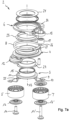
- the Figures 1a) to 1d show a spring 8 according to the invention in a first embodiment.
- the spring 8 has about 1.5 turns, or extends over about 540° around a Spring axis A8, whereby any other number of turns between a minimum of 1.25 and a maximum of 2.5 (450° and 900°) is also conceivable.
- the spring 8 has a first turn section 43 which extends in a plane E43 with a constant radius R43 over an angular range of approximately 110° to 120° around the spring axis A8.
- the term turn section means that the spring in this section is wound around the spring axis with a concave curvature.
- the plane E43 which is spanned by the first turn section 43, is at least essentially perpendicular to the spring axis A8, which is intended to include certain manufacturing and/or position tolerances.
- the first turn section 43 without a pitch is followed by a transition or pitch section 44 which extends over an angular range of approximately 60° to 70°.
- the spring 8 leaves the plane E43, i.e. the spring has a pitch component in the axial direction in this section.
- the pitch section 44 opens into a second winding section 45, which lies in a plane E45 parallel to the plane E43.
- the second winding section 45 extends from the pitch section 44 to the end of the winding section 45 over approximately one full turn, i.e. an angular range of approximately 360°.
- At the end of the second winding section 45 there is a second end section 27, which is bent radially outwards.
- the spring 8 has a constant radius R43 over the first coil section 43, the pitch section 44 and part of the second coil section 45.
- the circular arc with radius R43 extends from the coil end 42 to a first transition region 46 of the second coil section 45. From this first transition region 46 to the second transition region 47, the second coil section 45 has a spiral course in relation to the spring axis A8, in which the spring 8 has a radial pitch component and leaves the first radius R43 radially outwards. This is achieved by a radius R47, the center point M47 of which is offset from the spring axis A8 and which is larger than the radius R43.
- the second winding section 45 From the second transition area 47 to the winding end 49, the second winding section 45 has a constant radius R49 around the spring axis A8, which is larger than the radius R43 of the first winding section 43. In Figure 1b ) it is clear that this End region of the second winding section 45 runs coaxially to the pitch section 44.
- the angle ranges and radius profiles given are examples and that different angle ranges or radii can be selected.
- the key design features of the spring 8 are that the first winding end 42 has an axial offset Va relative to the area 48 offset by 360° around the spring axis A8, and that the second winding end 49 has a radial distance Vr relative to a winding area 50 offset by 360° around the spring axis A8.
- the area offset by 360° refers to the winding area that is exactly one turn away from the associated end.
- the axial offset Va or the radial offset Vr in this case is smaller than a largest diameter d8 of the spring wire.
- the first winding end 42 has a radial overlap with the winding area 48, which is offset by 360°, resulting in a small size in the radial direction in this circumferential area of the spring.
- the second winding end 49 has an axial overlap with the area 50, which is offset by 360°, resulting in a particularly flat structure in this circumferential section.
- the two winding ends 42, 49 of the spring 8 are offset relative to one another by approximately 180° in the circumferential direction, with certain deviations of preferably up to ⁇ 30° being possible.
- the spring 8 has at least one helical part with a constant radius over the circumference (R43, R49) and at least one spiral part with a variable radius over the circumference in relation to the spring axis A8 (R47), as well as two winding sections 43, 45 which extend in two mutually parallel planes E43, E45. This results in a particularly compact structure of the spring 8 with flat contact surfaces.
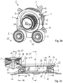
- the Figures 2a ), 2b) and 2c which are described together below, show a belt tensioning device 2 according to the invention in a first embodiment.
- the belt tensioning device 2 comprises a base body 3, a first tensioning arm 4 with a first tensioning roller 5, a second tensioning arm 6 with a second tensioning roller 7 and a spring element 8, which pre-tensions the two tensioning arms 4, 6 against each other in the circumferential direction.
- the spring element 8 can be as in the Figures 1a) to 1d ) or, as shown here, have a slightly modified design.
- the base body 3 can be attached to a unit or a component connected to the unit.
- the unit can in principle be any machine that is part of the belt drive, that is to say in particular any of the auxiliary units driven by the main engine of the motor vehicle, such as a generator, water pump or the like.
- the base body 3 has a fastening section 9, in particular with four flange projections 10 distributed over the circumference that protrude radially outwards and have holes through which screws can be inserted for fastening to a unit.
- the belt tensioning device according to the present embodiment is designed in such a way that the bearing of the tensioning arms 4, 6 is between the unit, or the fastening section 9 of the base body 3, and the middle belt plane, which is clamped by the belt in the assembled state.
- the base body 3 also has a flange section 11 which adjoins the fastening section 9 radially on the inside and serves to axially support the second clamping arm 6.
- the flange section 11 merges radially on the inside into a sleeve section 15 on which the first or second clamping arm 4, 6 is radially mounted.
- An annular disk 21 is fixed to the free end of the sleeve section 15 as a closure. In the present case, this is done by flanging an end edge of the sleeve section 15, although other fastening methods are also conceivable.
- the annular disk 21 forms a support surface for axially supporting the first or second clamping arm 4, 6.
- the base body 3 is in the present case designed as a steel component, which can be manufactured from sheet metal by forming, although it is understood that other materials and manufacturing processes are also possible.
- the two tensioning arms 4, 6 can each be pivoted relative to one another about the pivot axis A3, with the spring element 8 arranged between the two tensioning arms 4, 6 counteracting the pivoting movement.
- the structural unit composed of the two tensioning arms 4, 6 and the spring element 8 can be freely rotated relative to the base body 3 about the pivot axis A3, i.e. by 360° and more. It is intended that the pivot axis A3, in the assembled state of the belt tensioning device 2, lies within the diameter of the drive pulley 40 of the unit 35, preferably essentially coaxial with the drive axis A40 of the drive pulley.
- the tensioning arms 4, 6 each have a support section 12, 13 that protrudes radially outward from a ring section of the respective tensioning arm 4, 6.
- a tensioning roller 5, 7 is attached to the support section 12, 13 and is rotatably mounted by means of corresponding bearings 18, 18' about axes of rotation A5, A7 parallel to the pivot axis A3.
- the bearing 18 for the first tensioning roller 5 is mounted on a pin of the support section 12, into which a screw 14 is screwed for fastening.
- the second tensioning roller 7 is rotatably mounted on an intermediate element 17 that is fixed to the second support section 13 by means of the screw 14'. Discs 16, 16' prevent dirt from penetrating the bearings 18, 18' of the tensioning rollers 5, 7.
- the first clamping arm 4 has a bearing section 19 radially inside for rotatable mounting on the base body 3.
- the second clamping arm 5 has a bearing section 20 for rotatable mounting relative to the first bearing section 19 or to the base body 3. It can be seen that the first bearing section 19 and the second bearing section 20 are nested in one another.
- the second bearing section 20 is axially supported relative to the base body 3 via a bearing 22, which is designed in particular in the form of a bearing disk, which is received in an inner recess of the second clamping arm 6 and on an annular shoulder 11 of the base body 3. rests.
- a further bearing 23 is provided, which is designed in particular in the form of a sliding ring with an L-shaped cross section and forms an axial and radial bearing between the two clamping arms 4, 6.
- a third bearing 24 is provided, which is designed in particular in the form of a sliding ring with an L-shaped cross section and forms an axial and radial bearing for the first clamping arm 4 relative to the base body 3.
- the third bearing 24 is supported axially relative to the annular disk 21, which is fixed by flanging the end collar of the sleeve section 15 after the first bearing 22, the second clamping arm 6, the second bearing 23, the first clamping arm 4 and the third bearing 24 have been mounted on the base body 3.
- the clamping arms 4, 6 are at least essentially in the same plane as the bearings 23, 24, so that the axial installation space is small.
- the spring 8 is a wound spring element which, when installed, extends in the circumferential direction around the pivot axis A3.
- the spring axis A8 which can be defined, for example, by the sum of the average diameters of the turns, is at least substantially coaxial with the pivot axis A3 of the base body 3.
- substantially coaxial means that a certain offset of the spring axis A8 from the pivot axis A3 is conceivable, particularly in the case of wound spring elements with a spiral section.
- the spring 8 is designed in the form of a helical spring, the number of turns of which is approximately between 1.25 and 2.5 (corresponding to 450° to 900°).
- a first end section 26 of the spring 8 is supported in the circumferential direction relative to the first tension arm 4 and the second end section 27 is supported in the circumferential direction relative to the second tension arm 6.
- the two end sections 26, 27 are each bent radially outwards and held in corresponding receptacles of the clamping arms 4, 6 in a rotationally secure manner.
- the spring 8 is inserted between a support surface 29 of the first clamping arm 4 and a support surface 30 of the second clamping arm 6 with axial preload.
- the spring 8 is thus held axially free of play in relation to the clamping arms 4, 6, so that the generation of undesirable noises is avoided.
- the support surfaces 29, 30 of the two tension arms 4, 6 extend in the circumferential direction and each have a ramp shape which is adapted to the pitch of the coil spring 8.
- the spring 8 In the installed state, the spring 8 is under strong compressive preload in the circumferential direction, i.e. the spring 8 is expanded compared to its relaxed state, so that the spring 8 urges the two tension arms 4, 6 towards each other.
- the tension arms 4, 6 are moved away from each other against the preload force of the spring 8 and a locking pin 32 is inserted into a first hole 33 in the first tension arm 4 and a second hole 34 in the second tension arm 6.
- the locking pin 32 After the belt tensioning device 2 has been mounted on the unit 35 and the belt 39 has been placed on it, the locking pin 32 is pulled so that the tension arms 4, 6 are urged towards each other in the circumferential direction by the spring 8 and the tension rollers 5, 7 preload the belt 39.
- the spring 8 Due to the small number of turns, the spring 8 has a short axial length, which leads to a small axial size of the belt tensioning device 2. Particularly noteworthy is the ratio of the diameter D8 of the spring 8 to the axial length L8 of the spring 9 in the installed state, which in this case is approximately 6.0. This achieves a particularly compact arrangement with good spring properties at the same time. It goes without saying that the invention is not limited to this ratio. Rather, other values are also possible, with the ratio of diameter to axial length preferably being in a range of greater than 5.0, in particular greater than 7.0. The choice of ratio depends, among other things, on the wire diameter of the spring wire, whereby the stiffness of the spring increases with increasing wire diameter, and vice versa.
- the ratio R5/R8 is approximately 1.35, although it is understood that other values are also conceivable.
- the ratio of the average radius R8 of the spring 8 to the axial distance R5 is less than 1.5, in particular less 1.3 or even less than 1.0, and greater than 0.5, in particular greater than 0.7. This makes it possible to achieve high pre-tensioning forces of the tension rollers 5, 7 on the belt 39.
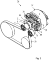
- FIG 3 shows the belt tensioning device 2 according to the invention according to the Figures 2a) to 2c ) in the assembled state to a unit 35.
- the belt tensioning device 2 and the unit 35 together form a unit arrangement 36.
- the unit 35 is designed in the form of a generator (alternator).
- the housing 37 of the generator can be seen, which can be connected to an engine block via fastening means. It is understood, however, that the unit can also be another working machine that is part of the belt drive, for example an auxiliary unit such as a pump.
- the belt tensioning device 2 is attached to the front of the generator 35. This is done by means of the circumferentially distributed connection flanges 10, into which screws 38 can be inserted and screwed to the housing 37 of the generator 35.
- the endless belt 39 and the pulley 40 can also be seen, which can be connected to the drive shaft 41 of the generator 35 in a rotationally fixed manner by means of a screw connection.
- the base body 3 or the belt tensioning device 2 is designed such that - in the assembled state of the belt tensioning device 2 on the unit 35 - the pivot axis A3 of the tensioning arms 4, 6 is arranged within the outer diameter of the drive shaft, preferably substantially coaxially to the drive axis of rotation.
- FIG 4 shows a belt tensioning device 2 according to the invention in a further embodiment.
- the present belt tensioning device 2 largely corresponds to the embodiment according to the Figures 2a) to 2c ), so that reference is made to the above description with regard to the similarities.
- Identical or modified components are provided with the same reference numerals as in the Figures 2a) to 2c ).
- the spring 8 of the Figure 4 The embodiment shown corresponds to the one in the Figures 1a) to 1d ) so that reference is made to the above description; the same details are with the same reference switches as in Figure 1 provided.
- a special feature of the embodiment according to Figure 4 is that the installation position of the spring 8 relative to the tensioning arms 4, 6 is selected such that the two supports 12, 13 or the tensioning rollers 5, 7 of the tensioning arms 4, 6 attached thereto are arranged in the circumferential region of the spring 8 in which the spring 8 has the flattest structure.
- the spring 8 has an axial thickness which only corresponds to the diameter d8 of the spring wire.
- This flat circumferential region which is formed by a part of the second winding section 45, is in the right-hand half of the section of Figure 4
- the first winding section 43 which is axially spaced relative to the second winding section 45, as shown in the left half of the section of Figure 4 recognizable.
- the winding overlap of the winding sections 43, 44, 45 required for the spring effect is placed in the circumferential area which is opposite the tension rollers 5, 7.
- the belt tensioning device 2 has a particularly flat axial size due to this design.
- the structural design, in particular the bearing of the clamping arms 4, 6 is similar to that in the Figures 2a) to 2c ) shown construction.
- a special feature of the present embodiment according to Figure 4 consists in the fact that the two clamping arms 4, 6 are made as formed parts from sheet metal. An annular space is formed between a flange section 51 of the first clamping arm 4 and a flange section 52 of the second clamping arm 6, which is axially spaced therefrom, in which the spring 8 is accommodated.
- the two clamping arms 4, 6 are axially supported against each other via an annular spacer 53.
- Figure 5 shows a modified embodiment for the mounting of the clamping arms 4, 6 on the base body 3 with a nested clamping arms 4, 6.
- the second clamping arm 6 has an L-shaped profile in half longitudinal section with an inner sleeve section, which is rotatably mounted on the base body 3 with the interposition of a bearing bush 24, and a flange section protruding from it.
- the first clamping arm 4 is designed in the shape of a disk and on the second
- the clamping arm 6 is rotatably mounted with a bearing bush 23 in between.
- the axial support is provided by the disc 21 which is connected to the base body 3 by flanging the edge.
- Figure 6 shows a further modified embodiment for the mounting of the clamping arms 4, 6 on the base body 3 with a parallel arrangement.
- the radially inner bearing sections of the two clamping arms 4, 6 are arranged axially adjacent to one another and are both rotatably mounted on the sleeve-shaped section 15 of the base body 3 with the interposition of bearing bushes 23, 24.
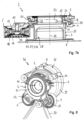
- FIGS. 7a ) and 7b ) show a belt tensioning device 2 according to the invention in a further embodiment. This corresponds in large parts to the embodiment according to the Figures 2a) to 2c ), so that with regard to the similarities, reference is made to the above description. Identical or modified components are provided with the same reference numbers as in the embodiment according to the Figures 2a) to 2c ). The following mainly explains the differences of the present embodiments.
- the belt tensioning device 2 is designed in such a way that the bearing of the tensioning arms 4, 6 on the base body 3 is behind the belt plane from the perspective of the unit 35.
- a center plane E3 of the bearing of the tensioning arms 4, 6 on the base body 3 is arranged axially offset from a center plane E18 of the belt 39 in the direction of the engine compartment.
- the belt plane E18 is defined as the plane which is spanned by the center of the belt in the assembled state.
- the bearing of the tensioning arms 4, 6 is as in the embodiment according to Figure 2a) to 2c ), with the difference that the axial orientation of the tensioning arms 4, 6 or the bearing pins for the tensioning rollers 5, 7 are directed towards the unit 35.
- the base body 3 has a relatively long intermediate section 25 which forms the opening 28 into which the drive shaft or the drive pulley 40 can be inserted.
- Figure 8 shows the belt tensioning device 2 according to the invention according to the Figures 7a ) and 7b ) in assembled state to an aggregate 35.
- the belt tensioning device 2 and the aggregate 35 together form the aggregate arrangement 36.
- the design of the aggregate or the aggregate arrangement please refer to the above description of Figure 3 which apply here accordingly.
- the special feature of the present embodiment is that the bearing 23, 24 of the tensioning arms 4, 6 on the base body 3, viewed from the generator, is located behind the belt plane, which essentially corresponds to the bearing center plane E18 of the tensioning roller bearings 18, 18'.
- the base body 3 has the intermediate section 25 extending in the axial direction between the fastening section 9 and the sleeve-shaped section 15.
- the opening 28 formed by the intermediate section 25 is larger than the largest outer diameter of the drive pulley 40.
- the belt tensioning device according to the present embodiment can also be attached to the unit even when the drive pulley is mounted. In the mounted state, the drive shaft or the drive pulley dips into the opening 28 of the base body without contact, which also applies to the above embodiments. A sufficient air supply can be ensured in air-cooled generators by varying the diameter of the opening 28.
Landscapes
- Engineering & Computer Science (AREA)
- General Engineering & Computer Science (AREA)
- Mechanical Engineering (AREA)
- Devices For Conveying Motion By Means Of Endless Flexible Members (AREA)
Applications Claiming Priority (1)
| Application Number | Priority Date | Filing Date | Title |
|---|---|---|---|
| DE102013102562.5A DE102013102562B4 (de) | 2013-03-13 | 2013-03-13 | Verwendung einer Feder in einer Riemenspannvorrichtung, Riemenspannvorrichtung und Aggregatanordnung |
Publications (3)
| Publication Number | Publication Date |
|---|---|
| EP2778472A1 EP2778472A1 (de) | 2014-09-17 |
| EP2778472C0 EP2778472C0 (de) | 2024-08-21 |
| EP2778472B1 true EP2778472B1 (de) | 2024-08-21 |
Family
ID=50342127
Family Applications (1)
| Application Number | Title | Priority Date | Filing Date |
|---|---|---|---|
| EP14000910.1A Active EP2778472B1 (de) | 2013-03-13 | 2014-03-13 | Feder, Riemenspannvorrichtung und Aggregatanordnung |
Country Status (7)
| Country | Link |
|---|---|
| US (1) | US9453561B2 (pl) |
| EP (1) | EP2778472B1 (pl) |
| KR (1) | KR102213543B1 (pl) |
| CN (1) | CN104048007B (pl) |
| DE (1) | DE102013102562B4 (pl) |
| ES (1) | ES2988593T3 (pl) |
| PL (1) | PL2778472T3 (pl) |
Families Citing this family (41)
| Publication number | Priority date | Publication date | Assignee | Title |
|---|---|---|---|---|
| DE102008025552B4 (de) * | 2008-05-28 | 2020-06-10 | Muhr Und Bender Kg | Riemenspannvorrichtung für Starter-Generator-Anwendung |
| US9334932B2 (en) * | 2011-05-13 | 2016-05-10 | Litens Automotive Partnership | Intelligent belt drive system and method |
| DE102011082330B4 (de) * | 2011-08-12 | 2014-08-07 | Schaeffler Technologies Gmbh & Co. Kg | Spannvorrichtung für einen Riementrieb und Elektromaschine mit einer derartigen Spannvorrichtung |
| EP2938905B1 (en) | 2012-12-26 | 2018-10-17 | Litens Automotive Partnership | Orbital tensioner assembly |
| CN104981628B (zh) * | 2013-02-07 | 2018-10-26 | 日本发条株式会社 | 负载附加装置 |
| US10520066B2 (en) * | 2014-06-26 | 2019-12-31 | Litens Automotive Partnership | Orbital tensioner assembly |
| US9759293B2 (en) | 2014-10-21 | 2017-09-12 | Litens Automotive Partnership | Endless drive arrangement and improved two-armed tensioning system for same |
| DE102014117094A1 (de) * | 2014-11-21 | 2016-05-25 | Muhr Und Bender Kg | Riemenspannvorrichtung |
| ES2903427T3 (es) * | 2015-02-06 | 2022-04-01 | Litens Automotive Inc | Disposición de accionamiento sin fin para vehículos híbridos que utiliza un tensor de dos brazos con brazos que no orbitan |
| FR3032746B1 (fr) * | 2015-02-16 | 2018-08-03 | Valeo Equipements Electriques Moteur | Machine electrique tournante dotee d'une poulie de reception d'une courroie et d'un dispositif de reglage de la tension de la courroie |
| WO2017152255A1 (en) * | 2015-04-02 | 2017-09-14 | Litens Automotive Partnership | Accessory drive tensioner with improved arrangement of tensioner arm and biasing member |
| DE102015210002B4 (de) | 2015-06-01 | 2020-03-26 | Schaeffler Technologies AG & Co. KG | Riemenspanner |
| DE102015212084A1 (de) | 2015-06-29 | 2016-12-29 | Schaeffler Technologies AG & Co. KG | Pendelspanner mit gezielt einstellbarer Dämpfung |
| DE102016113803A1 (de) * | 2015-07-28 | 2017-02-02 | Steering Solutions Ip Holding Corporation | Riemenscheibenbaugruppe mit leerlaufrolle, kraftunterstützungssystem mit riemenscheibenbaugruppe und verfahren |
| DE102015215812B4 (de) | 2015-08-19 | 2020-03-26 | Schaeffler Technologies AG & Co. KG | Riemenspanner |
| DE102015115750A1 (de) * | 2015-09-17 | 2017-03-23 | Muhr Und Bender Kg | Riemenspannvorrichtung |
| JP6659454B2 (ja) * | 2016-05-13 | 2020-03-04 | Ntn株式会社 | オートテンショナ |
| CN109219714B (zh) | 2016-05-30 | 2021-10-15 | 利滕斯汽车合伙公司 | 连续传动装置及用于连续传动装置的张紧系统 |
| KR101795289B1 (ko) * | 2016-07-26 | 2017-11-07 | 현대자동차주식회사 | 오토텐셔너 및 오토텐셔너 일체형 엔진 보기류 |
| DE102016217933B4 (de) | 2016-09-20 | 2020-06-04 | Schaeffler Technologies AG & Co. KG | Riemenspanner |
| DE102016221797B4 (de) * | 2016-11-08 | 2020-03-26 | Schaeffler Technologies AG & Co. KG | Spannvorrichtung |
| DE102017107047A1 (de) * | 2017-03-31 | 2018-10-04 | Muhr Und Bender Kg | Spannvorrichtung mit Verstellmechanismus und Verfahren zum Einstellen des Drehmoments der Spannvorrichtung |
| DE102017116000A1 (de) | 2017-07-17 | 2019-01-17 | Muhr Und Bender Kg | Riemenspannvorrichtung |
| US10962092B2 (en) * | 2017-09-08 | 2021-03-30 | Gates Corporation | Tensioner and method |
| DE102017217645A1 (de) * | 2017-10-05 | 2019-04-11 | Bayerische Motoren Werke Aktiengesellschaft | Riemenspannvorrichtung |
| DE102017124783B3 (de) * | 2017-10-24 | 2019-03-21 | Muhr Und Bender Kg | Spannvorrichtung |
| DE102018120933B4 (de) | 2017-10-27 | 2024-08-14 | Schaeffler Technologies AG & Co. KG | Riemenspanner |
| US10746264B2 (en) * | 2017-11-16 | 2020-08-18 | Gates Corporation | Rotary tensioner |
| CN110529571A (zh) * | 2018-05-24 | 2019-12-03 | 宁波丰茂远东橡胶有限公司 | 传动带张紧设备及其应用 |
| KR102552020B1 (ko) * | 2018-10-19 | 2023-07-05 | 현대자동차 주식회사 | 하이브리드 차량용 텐셔너 |
| CN111734802A (zh) * | 2019-03-25 | 2020-10-02 | 舍弗勒技术股份两合公司 | 皮带张紧器 |
| US11125305B2 (en) * | 2019-06-20 | 2021-09-21 | Gates Corporation | Tensioner |
| DE102019117170B4 (de) * | 2019-06-26 | 2023-01-12 | Schaeffler Technologies AG & Co. KG | Riemenspanner mit einer Pressfüge-Formschlussverbindung |
| US11333223B2 (en) * | 2019-08-06 | 2022-05-17 | Gates Corporation | Orbital tensioner |
| WO2021142175A1 (en) * | 2020-01-08 | 2021-07-15 | Gates Corporation | Preloaded tensioner device and belt assembly |
| DE102020004335A1 (de) * | 2020-07-20 | 2022-01-20 | Muhr Und Bender Kg | Riemenspannvorrichtung und Riementrieb mit einer solchen Riemenspannvorrichtung |
| CN116075656A (zh) * | 2020-08-11 | 2023-05-05 | 三菱自动车工业株式会社 | 皮带传动装置 |
| CN114251421A (zh) * | 2020-09-23 | 2022-03-29 | 舍弗勒技术股份两合公司 | 导向件、机械式张紧器和机械式张紧器的装配方法 |
| US20220099165A1 (en) * | 2020-09-28 | 2022-03-31 | Caterpillar Inc. | Engine accessory drive system and one-piece bracket for same |
| EP4476468A4 (en) * | 2022-02-07 | 2026-02-11 | Litens Automotive Inc | Tensioner with lock, equipped with a projecting part comprising first and second parts |
| US20240344595A1 (en) * | 2023-04-11 | 2024-10-17 | Fca Us Llc | Dual arm tensioner with hydraulic strut |
Family Cites Families (10)
| Publication number | Priority date | Publication date | Assignee | Title |
|---|---|---|---|---|
| DE3208184C1 (de) * | 1982-03-06 | 1983-10-06 | Daimler Benz Ag | Spannvorrichtung fuer einen Huelltrieb,insbesondere Riementrieb |
| US4758208A (en) * | 1987-07-13 | 1988-07-19 | General Motors Corporation | Automatic belt tensioner for vehicle combined starter-generator |
| US7588507B2 (en) * | 2001-04-13 | 2009-09-15 | Unitta Company | Thin autotensioner |
| DE102005039719A1 (de) * | 2005-08-23 | 2007-03-22 | Schaeffler Kg | Spannsystem für einen Zugmitteltrieb mit einem in den Zugmittel integrierten Startergenerator |
| DE102006014942A1 (de) * | 2006-03-31 | 2007-10-04 | Schaeffler Kg | Spannvorrichtung eines Zugmitteltriebs |
| DE102008025552B4 (de) * | 2008-05-28 | 2020-06-10 | Muhr Und Bender Kg | Riemenspannvorrichtung für Starter-Generator-Anwendung |
| DE102009007050B4 (de) * | 2009-01-29 | 2022-03-31 | Keiper Seating Mechanisms Co., Ltd. | Feder, insbesondere für eine Verriegelungsvorrichtung eines Fahrzeugsitzes |
| DE102011082330B4 (de) * | 2011-08-12 | 2014-08-07 | Schaeffler Technologies Gmbh & Co. Kg | Spannvorrichtung für einen Riementrieb und Elektromaschine mit einer derartigen Spannvorrichtung |
| DE102011053869B4 (de) | 2011-09-22 | 2020-03-26 | Muhr Und Bender Kg | Riemenspannvorrichtung für einen Riementrieb und Aggregatanordnung mit Riemenspannvorrichtung |
| ITTO20120548A1 (it) * | 2012-06-21 | 2013-12-22 | Dayco Europe Srl | Tenditore controllato per una trasmissione accessori e trasmissione accessori comprendente tale tenditore |
-
2013
- 2013-03-13 DE DE102013102562.5A patent/DE102013102562B4/de active Active
-
2014
- 2014-03-06 CN CN201410163794.3A patent/CN104048007B/zh active Active
- 2014-03-12 KR KR1020140028724A patent/KR102213543B1/ko active Active
- 2014-03-13 ES ES14000910T patent/ES2988593T3/es active Active
- 2014-03-13 US US14/207,840 patent/US9453561B2/en active Active
- 2014-03-13 PL PL14000910.1T patent/PL2778472T3/pl unknown
- 2014-03-13 EP EP14000910.1A patent/EP2778472B1/de active Active
Also Published As
| Publication number | Publication date |
|---|---|
| DE102013102562B4 (de) | 2021-05-27 |
| CN104048007A (zh) | 2014-09-17 |
| EP2778472C0 (de) | 2024-08-21 |
| PL2778472T3 (pl) | 2025-01-13 |
| EP2778472A1 (de) | 2014-09-17 |
| US9453561B2 (en) | 2016-09-27 |
| ES2988593T3 (es) | 2024-11-21 |
| KR20140112431A (ko) | 2014-09-23 |
| CN104048007B (zh) | 2018-03-23 |
| DE102013102562A1 (de) | 2014-09-18 |
| US20140315673A1 (en) | 2014-10-23 |
| KR102213543B1 (ko) | 2021-02-05 |
Similar Documents
| Publication | Publication Date | Title |
|---|---|---|
| EP2778472B1 (de) | Feder, Riemenspannvorrichtung und Aggregatanordnung | |
| EP2573423B9 (de) | Riemenspannvorrichtung für einen Riementrieb und Aggregatanordnung mit Riemenspannvorrichtung | |
| EP3023670B1 (de) | Riemenspannvorrichtung | |
| EP3431815B1 (de) | Riemenspannvorrichtung | |
| EP3099527B1 (de) | Stellantrieb für ein kraftfahrzeug, insbesondere für einen kraftfahrzeugsitz | |
| EP3477154B1 (de) | Spannvorrichtung | |
| EP3885609B1 (de) | Riemenspannvorrichtung | |
| EP3601845B1 (de) | Spannvorrichtung mit verstellmechanismus und verfahren zum einstellen des drehmoments der spannvorrichtung | |
| EP3374666B1 (de) | Spielfreie pendellagerung am entkopplungsspanner | |
| EP2957793A2 (de) | Riemenspannvorrichtung | |
| EP2385272B1 (de) | Spanner und Endlostriebanordnung | |
| WO2003036130A1 (de) | Spannvorrichtung | |
| DE10358315A1 (de) | Riemen-Spannvorrichtung | |
| EP3943778B1 (de) | Riemenspannvorrichtung und riementrieb mit einer solchen riemenspannvorrichtung | |
| DE102007026988A1 (de) | Zweimassenschwungrad, insbesondere für ein Kraftfahrzeug | |
| EP2621756B1 (de) | Verstelleinrichtung mit einem spindelgetriebe | |
| DE102016103197A1 (de) | Riemengetriebe und lenksystem | |
| EP2107274B1 (de) | Wälzelement und Getriebe zur Umwandlung einer Drehbewegung in eine Längsbewegung | |
| EP3748193A2 (de) | Spannanordnung mit spannrolle und vorrichtung zum einstellen einer spannanordnung | |
| DE102005052453A1 (de) | Spanneinrichtung für ein Zugmittel, insbesondere einen Riemen | |
| EP2138730A2 (de) | Lagerbuchse sowie Lager |
Legal Events
| Date | Code | Title | Description |
|---|---|---|---|
| PUAI | Public reference made under article 153(3) epc to a published international application that has entered the european phase |
Free format text: ORIGINAL CODE: 0009012 |
|
| 17P | Request for examination filed |
Effective date: 20140313 |
|
| AK | Designated contracting states |
Kind code of ref document: A1 Designated state(s): AL AT BE BG CH CY CZ DE DK EE ES FI FR GB GR HR HU IE IS IT LI LT LU LV MC MK MT NL NO PL PT RO RS SE SI SK SM TR |
|
| AX | Request for extension of the european patent |
Extension state: BA ME |
|
| R17P | Request for examination filed (corrected) |
Effective date: 20141010 |
|
| RBV | Designated contracting states (corrected) |
Designated state(s): AL AT BE BG CH CY CZ DE DK EE ES FI FR GB GR HR HU IE IS IT LI LT LU LV MC MK MT NL NO PL PT RO RS SE SI SK SM TR |
|
| 17Q | First examination report despatched |
Effective date: 20160524 |
|
| STAA | Information on the status of an ep patent application or granted ep patent |
Free format text: STATUS: EXAMINATION IS IN PROGRESS |
|
| GRAP | Despatch of communication of intention to grant a patent |
Free format text: ORIGINAL CODE: EPIDOSNIGR1 |
|
| STAA | Information on the status of an ep patent application or granted ep patent |
Free format text: STATUS: GRANT OF PATENT IS INTENDED |
|
| INTG | Intention to grant announced |
Effective date: 20240319 |
|
| GRAS | Grant fee paid |
Free format text: ORIGINAL CODE: EPIDOSNIGR3 |
|
| GRAA | (expected) grant |
Free format text: ORIGINAL CODE: 0009210 |
|
| STAA | Information on the status of an ep patent application or granted ep patent |
Free format text: STATUS: THE PATENT HAS BEEN GRANTED |
|
| AK | Designated contracting states |
Kind code of ref document: B1 Designated state(s): AL AT BE BG CH CY CZ DE DK EE ES FI FR GB GR HR HU IE IS IT LI LT LU LV MC MK MT NL NO PL PT RO RS SE SI SK SM TR |
|
| REG | Reference to a national code |
Ref country code: GB Ref legal event code: FG4D Free format text: NOT ENGLISH |
|
| REG | Reference to a national code |
Ref country code: CH Ref legal event code: EP |
|
| REG | Reference to a national code |
Ref country code: DE Ref legal event code: R096 Ref document number: 502014016860 Country of ref document: DE |
|
| REG | Reference to a national code |
Ref country code: IE Ref legal event code: FG4D Free format text: LANGUAGE OF EP DOCUMENT: GERMAN |
|
| RAP4 | Party data changed (patent owner data changed or rights of a patent transferred) |
Owner name: MUHR UND BENDER KG |
|
| U01 | Request for unitary effect filed |
Effective date: 20240920 |
|
| U07 | Unitary effect registered |
Designated state(s): AT BE BG DE DK EE FI FR IT LT LU LV MT NL PT RO SE SI Effective date: 20241014 |
|
| REG | Reference to a national code |
Ref country code: ES Ref legal event code: FG2A Ref document number: 2988593 Country of ref document: ES Kind code of ref document: T3 Effective date: 20241121 |
|
| REG | Reference to a national code |
Ref country code: SK Ref legal event code: T3 Ref document number: E 45134 Country of ref document: SK |
|
| PG25 | Lapsed in a contracting state [announced via postgrant information from national office to epo] |
Ref country code: NO Free format text: LAPSE BECAUSE OF FAILURE TO SUBMIT A TRANSLATION OF THE DESCRIPTION OR TO PAY THE FEE WITHIN THE PRESCRIBED TIME-LIMIT Effective date: 20241121 |
|
| PG25 | Lapsed in a contracting state [announced via postgrant information from national office to epo] |
Ref country code: GR Free format text: LAPSE BECAUSE OF FAILURE TO SUBMIT A TRANSLATION OF THE DESCRIPTION OR TO PAY THE FEE WITHIN THE PRESCRIBED TIME-LIMIT Effective date: 20241122 |
|
| PG25 | Lapsed in a contracting state [announced via postgrant information from national office to epo] |
Ref country code: IS Free format text: LAPSE BECAUSE OF FAILURE TO SUBMIT A TRANSLATION OF THE DESCRIPTION OR TO PAY THE FEE WITHIN THE PRESCRIBED TIME-LIMIT Effective date: 20241221 |
|
| PG25 | Lapsed in a contracting state [announced via postgrant information from national office to epo] |
Ref country code: HR Free format text: LAPSE BECAUSE OF FAILURE TO SUBMIT A TRANSLATION OF THE DESCRIPTION OR TO PAY THE FEE WITHIN THE PRESCRIBED TIME-LIMIT Effective date: 20240821 |
|
| PG25 | Lapsed in a contracting state [announced via postgrant information from national office to epo] |
Ref country code: RS Free format text: LAPSE BECAUSE OF FAILURE TO SUBMIT A TRANSLATION OF THE DESCRIPTION OR TO PAY THE FEE WITHIN THE PRESCRIBED TIME-LIMIT Effective date: 20241121 |
|
| PG25 | Lapsed in a contracting state [announced via postgrant information from national office to epo] |
Ref country code: RS Free format text: LAPSE BECAUSE OF FAILURE TO SUBMIT A TRANSLATION OF THE DESCRIPTION OR TO PAY THE FEE WITHIN THE PRESCRIBED TIME-LIMIT Effective date: 20241121 Ref country code: NO Free format text: LAPSE BECAUSE OF FAILURE TO SUBMIT A TRANSLATION OF THE DESCRIPTION OR TO PAY THE FEE WITHIN THE PRESCRIBED TIME-LIMIT Effective date: 20241121 Ref country code: IS Free format text: LAPSE BECAUSE OF FAILURE TO SUBMIT A TRANSLATION OF THE DESCRIPTION OR TO PAY THE FEE WITHIN THE PRESCRIBED TIME-LIMIT Effective date: 20241221 Ref country code: HR Free format text: LAPSE BECAUSE OF FAILURE TO SUBMIT A TRANSLATION OF THE DESCRIPTION OR TO PAY THE FEE WITHIN THE PRESCRIBED TIME-LIMIT Effective date: 20240821 Ref country code: GR Free format text: LAPSE BECAUSE OF FAILURE TO SUBMIT A TRANSLATION OF THE DESCRIPTION OR TO PAY THE FEE WITHIN THE PRESCRIBED TIME-LIMIT Effective date: 20241122 |
|
| PG25 | Lapsed in a contracting state [announced via postgrant information from national office to epo] |
Ref country code: SM Free format text: LAPSE BECAUSE OF FAILURE TO SUBMIT A TRANSLATION OF THE DESCRIPTION OR TO PAY THE FEE WITHIN THE PRESCRIBED TIME-LIMIT Effective date: 20240821 |
|
| U20 | Renewal fee for the european patent with unitary effect paid |
Year of fee payment: 12 Effective date: 20250307 |
|
| PGFP | Annual fee paid to national office [announced via postgrant information from national office to epo] |
Ref country code: PL Payment date: 20250218 Year of fee payment: 12 Ref country code: CZ Payment date: 20250225 Year of fee payment: 12 |
|
| PGFP | Annual fee paid to national office [announced via postgrant information from national office to epo] |
Ref country code: SK Payment date: 20250225 Year of fee payment: 12 |
|
| PLBE | No opposition filed within time limit |
Free format text: ORIGINAL CODE: 0009261 |
|
| STAA | Information on the status of an ep patent application or granted ep patent |
Free format text: STATUS: NO OPPOSITION FILED WITHIN TIME LIMIT |
|
| PGFP | Annual fee paid to national office [announced via postgrant information from national office to epo] |
Ref country code: ES Payment date: 20250404 Year of fee payment: 12 |
|
| 26N | No opposition filed |
Effective date: 20250522 |
|
| PG25 | Lapsed in a contracting state [announced via postgrant information from national office to epo] |
Ref country code: MC Free format text: LAPSE BECAUSE OF FAILURE TO SUBMIT A TRANSLATION OF THE DESCRIPTION OR TO PAY THE FEE WITHIN THE PRESCRIBED TIME-LIMIT Effective date: 20240821 |
|
| REG | Reference to a national code |
Ref country code: CH Ref legal event code: H13 Free format text: ST27 STATUS EVENT CODE: U-0-0-H10-H13 (AS PROVIDED BY THE NATIONAL OFFICE) Effective date: 20251023 |
|
| GBPC | Gb: european patent ceased through non-payment of renewal fee |
Effective date: 20250313 |
|
| PG25 | Lapsed in a contracting state [announced via postgrant information from national office to epo] |
Ref country code: GB Free format text: LAPSE BECAUSE OF NON-PAYMENT OF DUE FEES Effective date: 20250313 |
|
| PG25 | Lapsed in a contracting state [announced via postgrant information from national office to epo] |
Ref country code: CH Free format text: LAPSE BECAUSE OF NON-PAYMENT OF DUE FEES Effective date: 20250331 |
|
| PG25 | Lapsed in a contracting state [announced via postgrant information from national office to epo] |
Ref country code: IE Free format text: LAPSE BECAUSE OF NON-PAYMENT OF DUE FEES Effective date: 20250313 |
|
| U20 | Renewal fee for the european patent with unitary effect paid |
Year of fee payment: 13 Effective date: 20260313 |