EP2777771B1 - Sturzschutzvorrichtung mit einem Bremsmechanismus - Google Patents
Sturzschutzvorrichtung mit einem Bremsmechanismus Download PDFInfo
- Publication number
- EP2777771B1 EP2777771B1 EP14153850.4A EP14153850A EP2777771B1 EP 2777771 B1 EP2777771 B1 EP 2777771B1 EP 14153850 A EP14153850 A EP 14153850A EP 2777771 B1 EP2777771 B1 EP 2777771B1
- Authority
- EP
- European Patent Office
- Prior art keywords
- drum
- lifeline
- housing
- component
- safety device
- Prior art date
- Legal status (The legal status is an assumption and is not a legal conclusion. Google has not performed a legal analysis and makes no representation as to the accuracy of the status listed.)
- Active
Links
- 230000007246 mechanism Effects 0.000 title claims description 14
- 239000004020 conductor Substances 0.000 claims description 10
- 230000005294 ferromagnetic effect Effects 0.000 claims description 9
- 230000005672 electromagnetic field Effects 0.000 claims description 5
- XAGFODPZIPBFFR-UHFFFAOYSA-N aluminium Chemical compound [Al] XAGFODPZIPBFFR-UHFFFAOYSA-N 0.000 claims description 3
- 229910052782 aluminium Inorganic materials 0.000 claims description 3
- 238000004804 winding Methods 0.000 claims 3
- 239000000356 contaminant Substances 0.000 description 4
- 230000002452 interceptive effect Effects 0.000 description 2
- 238000009987 spinning Methods 0.000 description 2
- CBENFWSGALASAD-UHFFFAOYSA-N Ozone Chemical compound [O-][O+]=O CBENFWSGALASAD-UHFFFAOYSA-N 0.000 description 1
- 239000006096 absorbing agent Substances 0.000 description 1
- 238000006243 chemical reaction Methods 0.000 description 1
- 239000004519 grease Substances 0.000 description 1
- 230000001939 inductive effect Effects 0.000 description 1
- 238000002955 isolation Methods 0.000 description 1
- 238000004519 manufacturing process Methods 0.000 description 1
- 239000003921 oil Substances 0.000 description 1
- 125000006850 spacer group Chemical group 0.000 description 1
- XLYOFNOQVPJJNP-UHFFFAOYSA-N water Substances O XLYOFNOQVPJJNP-UHFFFAOYSA-N 0.000 description 1
Images


Classifications
-
- H—ELECTRICITY
- H02—GENERATION; CONVERSION OR DISTRIBUTION OF ELECTRIC POWER
- H02K—DYNAMO-ELECTRIC MACHINES
- H02K49/00—Dynamo-electric clutches; Dynamo-electric brakes
- H02K49/02—Dynamo-electric clutches; Dynamo-electric brakes of the asynchronous induction type
- H02K49/04—Dynamo-electric clutches; Dynamo-electric brakes of the asynchronous induction type of the eddy-current hysteresis type
- H02K49/043—Dynamo-electric clutches; Dynamo-electric brakes of the asynchronous induction type of the eddy-current hysteresis type with a radial airgap
-
- A—HUMAN NECESSITIES
- A62—LIFE-SAVING; FIRE-FIGHTING
- A62B—DEVICES, APPARATUS OR METHODS FOR LIFE-SAVING
- A62B1/00—Devices for lowering persons from buildings or the like
- A62B1/06—Devices for lowering persons from buildings or the like by making use of rope-lowering devices
- A62B1/14—Devices for lowering persons from buildings or the like by making use of rope-lowering devices with brakes sliding on the rope
-
- A—HUMAN NECESSITIES
- A62—LIFE-SAVING; FIRE-FIGHTING
- A62B—DEVICES, APPARATUS OR METHODS FOR LIFE-SAVING
- A62B35/00—Safety belts or body harnesses; Similar equipment for limiting displacement of the human body, especially in case of sudden changes of motion
- A62B35/0081—Equipment which can travel along the length of a lifeline, e.g. travelers
-
- A—HUMAN NECESSITIES
- A62—LIFE-SAVING; FIRE-FIGHTING
- A62B—DEVICES, APPARATUS OR METHODS FOR LIFE-SAVING
- A62B35/00—Safety belts or body harnesses; Similar equipment for limiting displacement of the human body, especially in case of sudden changes of motion
- A62B35/0043—Lifelines, lanyards, and anchors therefore
- A62B35/0062—Rail-form lifelines for permanent installation
Definitions
- the present invention relates to a fall protection safety device including a braking mechanism.
- Fall protection safety devices are well known in the art of fall protection safety equipment for use by workers performing tasks during which there is a risk a fall may occur.
- One type of safety device commonly used is a rail along the length of which a shuttle moves.
- the rail is typically connected to a support structure within the vicinity the worker is performing the task, and the shuttle is typically connected to a safety harness worn by the worker.
- An energy absorber may also be used with this type of safety device to reduce the amount of force transferred to the worker. Should a fall occur, the shuttle locks onto the rail thereby preventing the worker from falling any further. If the shuttle becomes contaminated with dirt, oil, grease, water, ice, or other types of debris or contaminants, the shuttle may not operate properly.
- One type of commonly used shuttle utilizes a wheel that rides on a rail or track to sense speed, and the wheel could be affected by contaminants. If the wheel has a rubber grip, the rubber grip could be degraded by ultraviolet light or ozone exposure.
- a self-retracting lifeline generally includes a housing containing a drum around which a cable, rope, webbing, or other suitable lifeline is wound.
- the drum is spring biased to pay out cable as tension pulling the cable is applied and to retract any of the cable that has been unwound from the drum as the tension on the cable is reduced or released.
- the housing also includes a brake assembly for stopping rotation of the drum when the cable suddenly unwinds from the drum at a rate greater than a predetermined maximum angular velocity.
- a self-retracting lifeline is typically connected to a support structure within the vicinity the worker is performing the task, and the end of the cable is typically connected to a safety harness worn by the worker.
- the support structure may include one or more structures.
- the cable is easily drawn out of the self-retracting lifeline housing as the worker moves away from the device, and the cable is automatically drawn back into the housing as the worker moves toward the device. Should a fall occur, the brake assembly within the device is automatically engaged by a centrifugal clutch assembly, which gradually and quickly stops the worker's fall by gradually and quickly stopping the rotation of the drum. As the rotation of the drum is stopped, additional cable is prevented from being paid out of the housing to stop the fall of the worker.
- Some self-retracting lifelines are sealed to prevent contaminants from interfering with the braking or locking mechanism.
- Another type of safety device commonly used is a descender or a controlled descent device, which generally include a braking mechanism to allow the worker to slowly descend to a safe location.
- GB-A-2140978 discloses a device utilizing energy conversion into heat by eddy currents for braking the descent of a refugee, e.g. from higher stories of a building in the event of a fire or other emergency.
- the device Includes a payoff reel rotatably mounted on a frame for paying off wire rope.
- the payoff reel is coupled via overdrive gears to a rotor of electrically conductive material which also is rotatably mounted on the frame and which rotates at a greatly increased speed in response to the rotation of the payoff reel.
- a permanent magnet or magnets of generally annular configuration are secured to the frame in an opposed relation to the rotor for inducing eddy currents therein upon rotation of the payoff reel.
- the induced eddy currents convert the energy of the revolving payoff reel into heat.
- a fall protection safety device including a braking mechanism comprises a first component, a second component configured and arranged to move relative to the first component, and at least one magnet operatively connected to one of the components and another of the components being at least partially made of a non-ferromagnetic and electrically conductive material.
- the at least one magnet and the non-ferromagnetic and electrically conductive material creating an electromagnetic field force when the second component moves at a rate greater than a predetermined rate relative to the first component.
- the first component is a housing and the second component includes a drum rotatably operatively connected to the housing, wherein the at least one magnet is directly operatively connected to the drum.
- the device further comprises a lifeline having an intermediate portion interconnecting a first end and a second end, the first end being operatively connected to the drum, the intermediate portion being wound about the drum, and the second end extending through the housing.
- the lifeline is paid out from the housing when sufficient tension is placed on the lifeline thereby rotating the drum.
- a repulsion force between the at least one magnet and the non-ferromagnetic and electrically conductive material reduces a rate at which the drum rotates in at least one of the first direction and the second direction.
- the present invention generally relates to a braking mechanism for use with a fall protection safety device.
- the braking mechanism could act as a brake, a lock, and/or a trigger mechanism suitable for the type of fall protection safety device.
- Fall protection safety devices with which the present invention could be used are self-retracting lifelines and descenders or controlled descent devices.
- an electromagnetic field (“EMF”) force could be used to at least enhance the braking mechanism or act as the braking mechanism of self-retracting lifelines and descenders or controlled descent devices.
- the housings of the self-retracting lifelines and descenders are at least partially made from a non-ferromagnetic, electrically conductive material such as, but not limited to, aluminum, and magnets are mounted on cylindrical or other axis-symmetric shapes that spin relative to the housings.
- the magnets spin because they are mechanically connected through gearing and drums to lifelines. The faster the magnets spin, the larger the EMF forces are exerted on them in the opposite direction they are spinning. Since the force is in the opposite direction to the movement of the magnets, a braking force is applied to the magnets. This braking force is transmitted through the gearing and the drums to the lifelines and is dissipated as heat.
- the magnets do not contact the housings and, thus, do not wear out as conventional braking mechanisms.
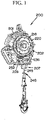
- An embodiment self-retracting lifeline constructed according to the principles of the present invention is designated by the numeral 200 in Figures 8 and 9.
- self-retracting lifeline Although one type of self-retracting lifeline is shown and described herein for use with the present invention, it is recognized that any suitable self-retracting lifeline could be used. Because self-retracting lifelines suitable for use with the present invention are well-known, only the components of the self-retracting lifeline 200 relevant to the description of the present invention are being described herein.
- the self-retracting lifeline 200 includes a housing 201 defining a cavity 202 having a first compartment 203, a second compartment 204, and a third compartment 206.
- a bore 205 extends at least partially through the housing 201 proximate a middle portion of the second compartment 204.
- the housing 201 also includes a cable exit 207.
- a drum 210 around which a lifeline 245 is wound, is rotatably connected to the housing 201 and fits within the first compartment 203.
- the lifeline 245 includes a first end (not shown) operatively connected to the drum 210, an intermediate portion (not shown) wound about the drum 210, and a second end 248 extending through the cable exit 207 of the housing 201.
- a brake mechanism 211 is operatively connected to the drum 210.
- the brake mechanism 211 includes several components in each of the three compartments.
- a base plate 212 is operatively connected to the drum 210, and brake discs 213 and pawls 214 biased with springs 215 are operatively connected to the base plate 212.
- a gear 218 fits within the first compartment 203 proximate the base plate 212 and includes inner teeth 219 and outer teeth 220.
- a bushing 223 fits within a bore (not shown) of the drum 210 to assist in rotation of the drum 210 about a shaft (not shown).
- a cover 224 is operatively connected to the gear 218 with fasteners 225.
- An isolation disc 222 reduces the friction between the pawls 214 and the cover 224.
- a bushing 226 fits within the bore 205 and a spacer 227 and a gear 228 fit about the bore 205.
- the gear 228 includes inner teeth 229 and outer teeth 230.
- a shaft 231 includes teeth 232a, teeth 232b, and teeth 233 extending outward therefrom proximate an intermediate portion of the shaft 231. The teeth are shown in Figure 9A.
- One end of the shaft 231 extends into the bushing 226 within the bore 205, the teeth 232a mate with the outer teeth 220 of the gear 218, the teeth 232b mate with the inner teeth 229 of the gear 228, and the teeth 233 selectively mate with a mode control assembly (not shown) such as that disclosed in U.S. Patent Application Publication Nos. 2010/0226748A1 and 2010/0224448A1 .
- a disc 235 is positioned proximate the housing and a cylinder 236 is positioned within the third compartment 206.
- the cylinder 236 includes a bore 237 and teeth 238 positioned about the bore 237.
- the teeth 238 mate with the outer teeth 230 of the gear 228.
- Magnets 239 are operatively connected to the cylinder 236, preferably proximate the cylinder's perimeter.
- a fastener 240 extends through the bore 237 and through a bore (not shown) in the housing to rotatably connect the cylinder 236 to the housing 201.
- the disc 235 is used to reduce friction as the cylinder 236 rotates.
- the brake discs 213 are not used to arrest a fall.
- This self-retracting lifeline is shown and described in rescue or descending mode but can be switched to a standard self-retracting lifeline fall arrest mode.
- the standard self-retracting lifeline fall arrest mode uses the brake discs to arrest a fall.
- This type of self-retracting lifeline is known in the art. Examples of this type of self-retracting lifeline are the SEALED-BLOK RSQ and the ULTRA-LOK RSQ by D B Industries, Inc. d/b/a Capital Safety USA of Red Wing, Minnesota. Other examples of this type of self-retracting lifeline are disclosed in U.S. Patent Application Publication Nos. 2010/0226748A1 and 2010/0224448A1 .
- the speed at which the drum 210 rotates is great enough to overcome the biasing force of the springs 215 so that the pawls 214 pivot outward from a disengaged position into an engaged position and at least one of the pawls 214 engages the inner teeth 219 of the gear 218.
- the gear 218 rotates, which causes the shaft 231 to rotate, which causes the gear 228 to rotate, which causes the cylinder 236 to rotate.
- the magnets 239 move relative to the housing 201 and the EMF forces exert a braking force on the drum 210.
- the braking force due to the EMF force generated between the magnets 239 and the housing 201 increases as the rotational velocity increases.
- the pawls of a self-retracting lifeline are commonly held in an unlocked position with springs, and during the retraction of the lifeline into the housing, the pawls will not typically move into a locking position because they typically only move into the locking position when the drum is rotated at a high enough speed in the direction to payout the lifeline.
- a common problem with self-retracting lifelines is that the pawls can lock at the end of the retraction of the lifeline into the housing if the rotation speed of the drum is high enough and then suddenly stops rotating to cause the pawls to move into a locking position. At the end of the retraction, with a fast spinning drum that suddenly stops, the pawls can be moved into a locking position and will engage the teeth. This causes jamming of the self-retracting lifeline.
- the drum By placing a plurality of magnets proximate the drum with the drum including at least one magnet in directly operative connection thereto and the housing being at least partially made of a non-ferromagnetic, electrically conductive material such as aluminum, as the drum rotates faster, the EMF force between the magnets and the non-ferromagnetic, electrically conductive material increases as the drum rotation speed increases. This provides a braking force on the drum to slow it down. By keeping the rotation speed below the speed at which the pawls pivot to move into the locking position, the self-retracting lifeline should not jam.
Landscapes
- Health & Medical Sciences (AREA)
- General Health & Medical Sciences (AREA)
- Business, Economics & Management (AREA)
- Emergency Management (AREA)
- Engineering & Computer Science (AREA)
- Power Engineering (AREA)
- Emergency Lowering Means (AREA)
- Braking Arrangements (AREA)
Claims (4)
- Eine Sturzschutzvorrichtung, die einen Bremsmechanismus aufweist, umfassend:eine erste Komponente;eine zweite Komponente, die konfiguriert und angeordnet ist, um sich relativ zu der ersten Komponente zu bewegen; undmindestens einen Magneten (239), der mit einer der Komponenten und einer anderen der Komponenten wirkverbunden ist, die mindestens teilweise aus einem nicht-ferromagnetischen und elektrisch leitfähigen Material hergestellt sind, wobei der mindestens eine Magnet und das nicht-ferromagnetische und elektrisch leitfähige Material eine elektromagnetische Feldkraft erzeugen, wenn sich die zweite Komponente mit einer Geschwindigkeit bewegt, die größer als eine vorbestimmte Geschwindigkeit relativ zu der ersten Komponente ist;wobei die erste Komponente ein Gehäuse (201) ist und die zweite Komponente eine Trommel (210) aufweist, die drehbar mit dem Gehäuse wirkverbunden ist, ferner umfassend ein Rettungsseil (245) mit einem Zwischenabschnitt, der ein erstes Ende und ein zweites Ende verbindet, wobei das erste Ende mit der Trommel wirkverbunden ist, wobei der Zwischenabschnitt um die Trommel gewickelt ist, und wobei sich das zweite Ende durch das Gehäuse erstreckt, wobei der mindestens eine Magnet direkt mit der Trommel wirkverbunden ist.
- Die Sturzschutzvorrichtung nach Anspruch 1, wobei die elektromagnetische Feldkraft eine Geschwindigkeit verringert, mit der sich die Trommel (210) in Abwickelrichtung dreht, wenn das Rettungsseil aus dem Gehäuse ausgegeben wird, wodurch eine Geschwindigkeit verringert wird, mit der das Rettungsseil aus dem Gehäuse ausgegeben wird.
- Die Sturzschutzvorrichtung nach einem der vorstehenden Ansprüche, wobei das nicht-ferromagnetische und elektrisch leitfähige Material Aluminium ist.
- Die Sturzschutzvorrichtung nach einem der vorstehenden Ansprüche, ferner umfassend:
ein Vorspannelement (215), welches das Gehäuse und die Trommel verbindet und die Trommel vorspannt, um sich in einer Wickelrichtung zu drehen, wobei das Vorspannelement überwunden wird, wenn eine ausreichende Spannung auf das Rettungsseil gelegt wird, wodurch die Trommel in einer Abwickelrichtung gedreht wird und das Rettungsseil ausgegeben wird, wobei das Rettungsseil um die Trommel gewickelt wird, wenn die Spannung von dem Rettungsseil freigegeben wird und sich die Trommel in der Wickelrichtung dreht; und wobei die elektromagnetische Feldkraft eine Geschwindigkeit, mit der sich die Trommel in Abwickelrichtung und Wickelrichtung dreht, verringert.
Applications Claiming Priority (3)
| Application Number | Priority Date | Filing Date | Title |
|---|---|---|---|
| US28955009P | 2009-12-23 | 2009-12-23 | |
| EP10801071.1A EP2516020B1 (de) | 2009-12-23 | 2010-12-23 | Sturzsicherungsvorrichtung mit bremsmechanismus |
| PCT/US2010/062007 WO2011079266A2 (en) | 2009-12-23 | 2010-12-23 | Fall protection safety device with a braking mechanism |
Related Parent Applications (2)
| Application Number | Title | Priority Date | Filing Date |
|---|---|---|---|
| EP10801071.1A Division EP2516020B1 (de) | 2009-12-23 | 2010-12-23 | Sturzsicherungsvorrichtung mit bremsmechanismus |
| EP10801071.1A Division-Into EP2516020B1 (de) | 2009-12-23 | 2010-12-23 | Sturzsicherungsvorrichtung mit bremsmechanismus |
Publications (3)
| Publication Number | Publication Date |
|---|---|
| EP2777771A2 EP2777771A2 (de) | 2014-09-17 |
| EP2777771A3 EP2777771A3 (de) | 2014-12-24 |
| EP2777771B1 true EP2777771B1 (de) | 2022-05-04 |
Family
ID=43735787
Family Applications (2)
| Application Number | Title | Priority Date | Filing Date |
|---|---|---|---|
| EP14153850.4A Active EP2777771B1 (de) | 2009-12-23 | 2010-12-23 | Sturzschutzvorrichtung mit einem Bremsmechanismus |
| EP10801071.1A Active EP2516020B1 (de) | 2009-12-23 | 2010-12-23 | Sturzsicherungsvorrichtung mit bremsmechanismus |
Family Applications After (1)
| Application Number | Title | Priority Date | Filing Date |
|---|---|---|---|
| EP10801071.1A Active EP2516020B1 (de) | 2009-12-23 | 2010-12-23 | Sturzsicherungsvorrichtung mit bremsmechanismus |
Country Status (11)
| Country | Link |
|---|---|
| US (1) | US8511434B2 (de) |
| EP (2) | EP2777771B1 (de) |
| JP (2) | JP5731540B2 (de) |
| CN (2) | CN102652029B (de) |
| AU (1) | AU2010336378B2 (de) |
| BR (1) | BR112012017336A2 (de) |
| CA (1) | CA2777855C (de) |
| DK (1) | DK2516020T3 (de) |
| MX (1) | MX2012007436A (de) |
| SG (1) | SG181479A1 (de) |
| WO (1) | WO2011079266A2 (de) |
Families Citing this family (50)
| Publication number | Priority date | Publication date | Assignee | Title |
|---|---|---|---|---|
| US8061479B2 (en) * | 2004-04-06 | 2011-11-22 | Harris Jr Rano J | Fall protection system |
| US20150217150A1 (en) * | 2004-04-06 | 2015-08-06 | Downsafe Systems, Llc | Fall protection system |
| AU2009295277A1 (en) * | 2008-09-19 | 2010-03-25 | Fallsafe Technology Pty Ltd | Fall protection system |
| NZ575464A (en) | 2009-03-10 | 2010-07-30 | Holmes Solutions Ltd | Improvements in and relating to braking mechanisms |
| US9056753B2 (en) | 2011-10-18 | 2015-06-16 | LynRus Aluminum Products, LLC | Disabling system for auto-arresting safety device |
| US9038777B2 (en) * | 2012-10-15 | 2015-05-26 | James F. Stearns Company LLP | Fall protection system |
| CN103007459A (zh) * | 2012-12-04 | 2013-04-03 | 马大勇 | 一种高空作业防坠落装置 |
| NZ619034A (en) * | 2013-12-16 | 2015-03-27 | Eddy Current Ltd Partnership | An assembly to control relative speed of movement between parts |
| EP3183803B1 (de) * | 2014-08-18 | 2021-04-14 | Eddy Current Limited Partnership | Abstimmung einer kinematischen beziehung zwischen elementen |
| KR102669783B1 (ko) * | 2014-08-18 | 2024-05-27 | 에디 커런트 리미티드 파트너쉽 | 래칭 장치 |
| AU2015304095B2 (en) * | 2014-08-18 | 2020-05-07 | Eddy Current Limited Partnership | Tuning of a kinematic relationship between members |
| WO2016029060A1 (en) * | 2014-08-20 | 2016-02-25 | Mcgowan John Lewis | Eddy current braking device for rotary systems |
| SG11201704352UA (en) | 2014-12-04 | 2017-06-29 | Eddy Current Ltd Partnership | Transmissions incorporating eddy current braking |
| SG11201704356SA (en) | 2014-12-04 | 2017-06-29 | Eddy Current Ltd Partnership | Energy absorbing apparatus |
| CN112003451B (zh) * | 2014-12-04 | 2023-09-08 | 涡流有限合伙公司 | 涡流制动器装置 |
| CN106999736B (zh) | 2014-12-04 | 2021-06-08 | 涡流有限合伙公司 | 更改涡流相互作用的方法 |
| CN106999737B (zh) | 2014-12-04 | 2021-02-26 | 涡流有限合伙公司 | 元件之间的闭锁激活 |
| DE102015104455B4 (de) * | 2015-03-25 | 2020-11-19 | Lorenz Hasenbach GmbH u. Co KG | Fallschutzläufer und Sicherungssystem mit einem derartigen Fallschutzläufer |
| GB2539418B (en) * | 2015-06-15 | 2019-10-02 | Swisslogo Ag | Self-braking pulley |
| KR20230074640A (ko) * | 2015-12-18 | 2023-05-30 | 에디 커런트 리미티드 파트너쉽 | 기동 시스템을 위한 가변 거동 제어 메커니즘 |
| US10413761B2 (en) | 2016-03-02 | 2019-09-17 | Msa Technology, Llc | Line retraction device having a damper assembly |
| US10864393B2 (en) | 2016-03-31 | 2020-12-15 | 2Innovate Llc | Fall control system and method of controlling a movement during fall event |
| US10328294B2 (en) * | 2016-04-12 | 2019-06-25 | Msa Technology, Llc | Load indicator for a fall protection apparatus |
| US10022570B2 (en) * | 2016-05-20 | 2018-07-17 | Bailout, LLC | Personal escape device with eddy current braking |
| US10166413B1 (en) | 2016-07-13 | 2019-01-01 | Bailout Systems, Llc | Controlled descent safety systems and methods |
| TWM537490U (zh) * | 2016-09-21 | 2017-03-01 | General Safety Company Ltd | 自動制動的安全裝置 |
| BR112019007569A2 (pt) | 2016-10-14 | 2019-07-02 | 3M Innovative Properties Co | métodos e aparelhos para gerar energia com o uso de dispositivos de proteção contra quedas |
| GB2556892B (en) * | 2016-11-23 | 2022-04-27 | Latchways Plc | Self-retracting lifeline fall arrest device |
| US10888723B2 (en) | 2017-01-25 | 2021-01-12 | Jeffrey D. Thompson | Self-retracting lanyard with fall protection harness tracker |
| US10792524B2 (en) | 2017-01-25 | 2020-10-06 | Jeffrey D. Thompson | Self-retracting lanyard with fall protection harness tracker |
| US10722739B2 (en) | 2017-01-25 | 2020-07-28 | Jeffrey D. Thompson | Controlled descent self-retracting lanyard |
| US9852598B1 (en) * | 2017-01-25 | 2017-12-26 | Jeffrey D. Thompson | Swing fall protection device |
| KR101889084B1 (ko) * | 2017-03-06 | 2018-08-16 | (주)미디어스페이스 | 추락 체험장치 |
| RU2726811C1 (ru) * | 2017-04-03 | 2020-07-15 | 3М Инновейтив Пропертиз Компани | Устройство для защиты от падения с защитным кожухом и втулочным узлом |
| EP3651863A4 (de) | 2017-07-13 | 2021-03-17 | 3M Innovative Properties Company | Absturzsicherungsvorrichtung mit reibungsbremse |
| CA3069227A1 (en) * | 2017-07-17 | 2019-01-24 | Safeworks, Llc | Climb assist and fall arrest system |
| JP2020529894A (ja) * | 2017-08-10 | 2020-10-15 | スリーエム イノベイティブ プロパティズ カンパニー | 落下抑制デバイスのイベントの生成及び監視 |
| US11524188B2 (en) * | 2018-10-09 | 2022-12-13 | Checkmate Lifting & Safety Ltd | Tensioning device |
| CN109568823B (zh) * | 2018-10-30 | 2021-03-02 | 广东欲丰电器制造有限公司 | 一种缓冲式防坠安全器 |
| CA3126393A1 (en) | 2019-01-14 | 2020-07-23 | Msa Technology, Llc | Fall protection compliance system and method |
| US11339610B2 (en) | 2019-09-26 | 2022-05-24 | Alpine Overhead Doors, Inc. | Auxiliary chain assembly for rolling doors and the like |
| WO2021188556A1 (en) * | 2020-03-18 | 2021-09-23 | TruBlue LLC | Line dispensing devices |
| US11534634B2 (en) | 2020-04-03 | 2022-12-27 | Honeywell International Inc. | Brake assembly for fall arrest system |
| US11779783B2 (en) | 2020-07-02 | 2023-10-10 | 3M Innovative Properties Company | Fall-protection apparatus comprising braking device with velocity-actuated, acceleration-modulated pawl(s) |
| US11759662B2 (en) | 2020-07-02 | 2023-09-19 | 3M Innovative Properties Company | Fall-protection apparatus comprising dual-actuatable braking device |
| WO2022009174A1 (en) | 2020-07-10 | 2022-01-13 | 3M Innovative Properties Company | Fall-protection apparatus with braking device comprising flexure-borne pawl |
| EP4178683A4 (de) | 2020-07-10 | 2024-04-17 | 3M Innovative Properties Company | Fallschutzvorrichtung mit bremsvorrichtung mit flexurgelagerter sperrklinke und trommelmontierter versteifung |
| US12076594B2 (en) * | 2020-11-23 | 2024-09-03 | Yoke Industrial Corp. | Fall arrester |
| KR102672742B1 (ko) * | 2022-08-09 | 2024-06-05 | 한국전력공사 | 드래그 다운먼트 |
| CN118166672B (zh) * | 2024-05-16 | 2024-07-19 | 山西路桥第六工程有限公司 | 一种桥梁施工防落装置 |
Family Cites Families (27)
| Publication number | Priority date | Publication date | Assignee | Title |
|---|---|---|---|---|
| JPS59217589A (ja) * | 1983-05-26 | 1984-12-07 | 株式会社宮野鉄工所 | 緩降機 |
| JPS60259278A (ja) * | 1984-06-04 | 1985-12-21 | 神鋼電機株式会社 | 渦電流式ブレ−キを使用した降下装置 |
| EP0247818A3 (de) * | 1986-05-28 | 1989-04-05 | Barrow Hepburn Equipment Ltd | Vorrichtung zur Verhinderung von Abstürzen |
| GB8612945D0 (en) * | 1986-05-28 | 1986-07-02 | Barrow Hepburn Equip Ltd | Safety line drum |
| JPH01256979A (ja) * | 1988-04-05 | 1989-10-13 | Fujii Denko Co Ltd | 無墜落高所作業方法 |
| JPH05155591A (ja) * | 1991-12-06 | 1993-06-22 | Shinko Electric Co Ltd | 電動ウインチ |
| JP2523883Y2 (ja) * | 1992-02-24 | 1997-01-29 | 株式会社三協精機製作所 | プーリ付調速器 |
| JPH07213633A (ja) * | 1994-02-01 | 1995-08-15 | Kazuo Kozutsumi | 回転制御装置及び昇降装置 |
| JPH11192316A (ja) * | 1997-12-26 | 1999-07-21 | Sohken Ohtex Kk | 制動装置 |
| US6397974B1 (en) * | 1998-10-09 | 2002-06-04 | Otis Elevator Company | Traction elevator system using flexible, flat rope and a permanent magnet machine |
| US6293376B1 (en) * | 1999-11-22 | 2001-09-25 | Magnetar Technologies Ltd | Apparatus including eddy current braking system |
| CN2422979Y (zh) * | 2000-04-18 | 2001-03-14 | 周广信 | 声光报警高楼自救逃生索 |
| US7096996B2 (en) * | 2002-07-26 | 2006-08-29 | Pavel V. Korchagin | High-rise fire-fighting, rescue and construction equipment |
| US6830126B2 (en) * | 2003-03-20 | 2004-12-14 | Michael Godwin | Rapid escape system for buildings |
| WO2005115899A1 (ja) * | 2004-05-28 | 2005-12-08 | Mitsubishi Denki Kabushiki Kaisha | エレベータのレール継ぎ目検出装置、及びエレベータ装置 |
| GB2428232B (en) * | 2005-07-09 | 2008-02-13 | Anthony Cuthbert | Traction arrangements |
| CN2853098Y (zh) * | 2005-09-30 | 2007-01-03 | 温贤胜 | 高空救生器 |
| CN2860528Y (zh) * | 2005-11-11 | 2007-01-24 | 南昌航空工业学院 | 高楼救生器 |
| CN1990064B (zh) * | 2005-12-31 | 2010-08-25 | 白孝林 | 磁阻尼救生器 |
| CN101254330A (zh) * | 2007-03-02 | 2008-09-03 | 项敏 | 一种非机械摩擦阻尼自动控速的方法及其装置 |
| US8272476B2 (en) * | 2007-12-10 | 2012-09-25 | Rapid Egress Descent Systems Ltd. | Descent control device |
| WO2009108041A1 (en) * | 2008-02-25 | 2009-09-03 | M.H. Instructions B.V. | Providing and obtaining first aid assistance in emergency situations |
| US8561759B2 (en) * | 2008-02-27 | 2013-10-22 | Rapid Vertical Egress System Holding B.V. | Rescue arrangement |
| US8141681B2 (en) * | 2008-04-07 | 2012-03-27 | Safeworks, Llc | Tower climbing assist device |
| FR2934342A3 (fr) * | 2008-07-25 | 2010-01-29 | Renault Sas | Dispositif de commande hydraulique d'embrayage et embrayage correspondant. |
| US10688323B2 (en) | 2009-03-09 | 2020-06-23 | D B Industries, Llc | Safety device with fall arrest and descending modes |
| US9764172B2 (en) | 2009-03-09 | 2017-09-19 | D B Industries, Llc | Safety device with fall arrest and descending modes |
-
2010
- 2010-12-23 WO PCT/US2010/062007 patent/WO2011079266A2/en active Application Filing
- 2010-12-23 DK DK10801071.1T patent/DK2516020T3/da active
- 2010-12-23 AU AU2010336378A patent/AU2010336378B2/en active Active
- 2010-12-23 EP EP14153850.4A patent/EP2777771B1/de active Active
- 2010-12-23 SG SG2012040572A patent/SG181479A1/en unknown
- 2010-12-23 CN CN201080056100.6A patent/CN102652029B/zh active Active
- 2010-12-23 MX MX2012007436A patent/MX2012007436A/es active IP Right Grant
- 2010-12-23 CA CA2777855A patent/CA2777855C/en active Active
- 2010-12-23 CN CN201510025790.3A patent/CN104667444B/zh active Active
- 2010-12-23 US US12/977,526 patent/US8511434B2/en active Active
- 2010-12-23 BR BR112012017336A patent/BR112012017336A2/pt not_active Application Discontinuation
- 2010-12-23 EP EP10801071.1A patent/EP2516020B1/de active Active
- 2010-12-23 JP JP2012546233A patent/JP5731540B2/ja active Active
-
2014
- 2014-02-14 JP JP2014026794A patent/JP5905499B2/ja not_active Expired - Fee Related
Also Published As
| Publication number | Publication date |
|---|---|
| EP2516020A2 (de) | 2012-10-31 |
| JP5731540B2 (ja) | 2015-06-10 |
| EP2777771A2 (de) | 2014-09-17 |
| US20110147125A1 (en) | 2011-06-23 |
| AU2010336378A1 (en) | 2012-05-17 |
| CN104667444B (zh) | 2021-04-27 |
| MX2012007436A (es) | 2012-07-23 |
| US8511434B2 (en) | 2013-08-20 |
| CN102652029A (zh) | 2012-08-29 |
| EP2777771A3 (de) | 2014-12-24 |
| WO2011079266A3 (en) | 2011-08-25 |
| CN104667444A (zh) | 2015-06-03 |
| CN102652029B (zh) | 2015-02-04 |
| AU2010336378B2 (en) | 2013-10-10 |
| JP5905499B2 (ja) | 2016-04-20 |
| WO2011079266A2 (en) | 2011-06-30 |
| DK2516020T3 (da) | 2015-06-22 |
| CA2777855C (en) | 2013-12-24 |
| BR112012017336A2 (pt) | 2016-04-19 |
| CA2777855A1 (en) | 2011-06-30 |
| EP2516020B1 (de) | 2015-05-27 |
| JP2014111188A (ja) | 2014-06-19 |
| SG181479A1 (en) | 2012-07-30 |
| JP2013515574A (ja) | 2013-05-09 |
Similar Documents
| Publication | Publication Date | Title |
|---|---|---|
| EP2777771B1 (de) | Sturzschutzvorrichtung mit einem Bremsmechanismus | |
| AU648627B2 (en) | Safety anchorages for controlling pay-out of a safety line | |
| CA1216831A (en) | Safety device | |
| EP1993674B1 (de) | Selbsteinziehendes verbindungsmittel und bremsmechanismus mit klinkensperre | |
| US4923037A (en) | Fall arrest device | |
| EP2638934B1 (de) | Bremsanordnung | |
| EP3544689B1 (de) | Sturzsicherungsvorrichtung mit kontrollierter retraktionsgeschwindigkeit | |
| US4457400A (en) | Emergency descent device | |
| US20100181145A1 (en) | Descent device | |
| JP2014521429A (ja) | 高所救助器具 | |
| TW202202198A (zh) | 包含具有速度致動加速度調節棘爪的制動裝置之墜落防護設備 | |
| US5344121A (en) | Safety winch | |
| EP2569057A2 (de) | Seilgriff | |
| CN110745727B (zh) | 电动葫芦和风力发电机 | |
| WO2009072828A2 (en) | Non-power apparatus for controlling descent | |
| NZ619680B2 (en) | Height rescue apparatus |
Legal Events
| Date | Code | Title | Description |
|---|---|---|---|
| PUAI | Public reference made under article 153(3) epc to a published international application that has entered the european phase |
Free format text: ORIGINAL CODE: 0009012 |
|
| 17P | Request for examination filed |
Effective date: 20140204 |
|
| AC | Divisional application: reference to earlier application |
Ref document number: 2516020 Country of ref document: EP Kind code of ref document: P |
|
| AK | Designated contracting states |
Kind code of ref document: A2 Designated state(s): AL AT BE BG CH CY CZ DE DK EE ES FI FR GB GR HR HU IE IS IT LI LT LU LV MC MK MT NL NO PL PT RO RS SE SI SK SM TR |
|
| PUAL | Search report despatched |
Free format text: ORIGINAL CODE: 0009013 |
|
| AK | Designated contracting states |
Kind code of ref document: A3 Designated state(s): AL AT BE BG CH CY CZ DE DK EE ES FI FR GB GR HR HU IE IS IT LI LT LU LV MC MK MT NL NO PL PT RO RS SE SI SK SM TR |
|
| RIC1 | Information provided on ipc code assigned before grant |
Ipc: A62B 1/14 20060101AFI20141114BHEP |
|
| STAA | Information on the status of an ep patent application or granted ep patent |
Free format text: STATUS: REQUEST FOR EXAMINATION WAS MADE |
|
| R17P | Request for examination filed (corrected) |
Effective date: 20150617 |
|
| RBV | Designated contracting states (corrected) |
Designated state(s): AL AT BE BG CH CY CZ DE DK EE ES FI FR GB GR HR HU IE IS IT LI LT LU LV MC MK MT NL NO PL PT RO RS SE SI SK SM TR |
|
| STAA | Information on the status of an ep patent application or granted ep patent |
Free format text: STATUS: EXAMINATION IS IN PROGRESS |
|
| 17Q | First examination report despatched |
Effective date: 20210325 |
|
| GRAP | Despatch of communication of intention to grant a patent |
Free format text: ORIGINAL CODE: EPIDOSNIGR1 |
|
| STAA | Information on the status of an ep patent application or granted ep patent |
Free format text: STATUS: GRANT OF PATENT IS INTENDED |
|
| INTG | Intention to grant announced |
Effective date: 20211123 |
|
| GRAS | Grant fee paid |
Free format text: ORIGINAL CODE: EPIDOSNIGR3 |
|
| GRAA | (expected) grant |
Free format text: ORIGINAL CODE: 0009210 |
|
| STAA | Information on the status of an ep patent application or granted ep patent |
Free format text: STATUS: THE PATENT HAS BEEN GRANTED |
|
| AC | Divisional application: reference to earlier application |
Ref document number: 2516020 Country of ref document: EP Kind code of ref document: P |
|
| AK | Designated contracting states |
Kind code of ref document: B1 Designated state(s): AL AT BE BG CH CY CZ DE DK EE ES FI FR GB GR HR HU IE IS IT LI LT LU LV MC MK MT NL NO PL PT RO RS SE SI SK SM TR |
|
| REG | Reference to a national code |
Ref country code: GB Ref legal event code: FG4D |
|
| REG | Reference to a national code |
Ref country code: CH Ref legal event code: EP |
|
| REG | Reference to a national code |
Ref country code: AT Ref legal event code: REF Ref document number: 1488390 Country of ref document: AT Kind code of ref document: T Effective date: 20220515 |
|
| REG | Reference to a national code |
Ref country code: IE Ref legal event code: FG4D Ref country code: DE Ref legal event code: R096 Ref document number: 602010068233 Country of ref document: DE |
|
| REG | Reference to a national code |
Ref country code: LT Ref legal event code: MG9D |
|
| REG | Reference to a national code |
Ref country code: NL Ref legal event code: MP Effective date: 20220504 |
|
| REG | Reference to a national code |
Ref country code: AT Ref legal event code: MK05 Ref document number: 1488390 Country of ref document: AT Kind code of ref document: T Effective date: 20220504 |
|
| PG25 | Lapsed in a contracting state [announced via postgrant information from national office to epo] |
Ref country code: SE Free format text: LAPSE BECAUSE OF FAILURE TO SUBMIT A TRANSLATION OF THE DESCRIPTION OR TO PAY THE FEE WITHIN THE PRESCRIBED TIME-LIMIT Effective date: 20220504 Ref country code: PT Free format text: LAPSE BECAUSE OF FAILURE TO SUBMIT A TRANSLATION OF THE DESCRIPTION OR TO PAY THE FEE WITHIN THE PRESCRIBED TIME-LIMIT Effective date: 20220905 Ref country code: NO Free format text: LAPSE BECAUSE OF FAILURE TO SUBMIT A TRANSLATION OF THE DESCRIPTION OR TO PAY THE FEE WITHIN THE PRESCRIBED TIME-LIMIT Effective date: 20220804 Ref country code: NL Free format text: LAPSE BECAUSE OF FAILURE TO SUBMIT A TRANSLATION OF THE DESCRIPTION OR TO PAY THE FEE WITHIN THE PRESCRIBED TIME-LIMIT Effective date: 20220504 Ref country code: LT Free format text: LAPSE BECAUSE OF FAILURE TO SUBMIT A TRANSLATION OF THE DESCRIPTION OR TO PAY THE FEE WITHIN THE PRESCRIBED TIME-LIMIT Effective date: 20220504 Ref country code: HR Free format text: LAPSE BECAUSE OF FAILURE TO SUBMIT A TRANSLATION OF THE DESCRIPTION OR TO PAY THE FEE WITHIN THE PRESCRIBED TIME-LIMIT Effective date: 20220504 Ref country code: GR Free format text: LAPSE BECAUSE OF FAILURE TO SUBMIT A TRANSLATION OF THE DESCRIPTION OR TO PAY THE FEE WITHIN THE PRESCRIBED TIME-LIMIT Effective date: 20220805 Ref country code: FI Free format text: LAPSE BECAUSE OF FAILURE TO SUBMIT A TRANSLATION OF THE DESCRIPTION OR TO PAY THE FEE WITHIN THE PRESCRIBED TIME-LIMIT Effective date: 20220504 Ref country code: ES Free format text: LAPSE BECAUSE OF FAILURE TO SUBMIT A TRANSLATION OF THE DESCRIPTION OR TO PAY THE FEE WITHIN THE PRESCRIBED TIME-LIMIT Effective date: 20220504 Ref country code: BG Free format text: LAPSE BECAUSE OF FAILURE TO SUBMIT A TRANSLATION OF THE DESCRIPTION OR TO PAY THE FEE WITHIN THE PRESCRIBED TIME-LIMIT Effective date: 20220804 Ref country code: AT Free format text: LAPSE BECAUSE OF FAILURE TO SUBMIT A TRANSLATION OF THE DESCRIPTION OR TO PAY THE FEE WITHIN THE PRESCRIBED TIME-LIMIT Effective date: 20220504 |
|
| PG25 | Lapsed in a contracting state [announced via postgrant information from national office to epo] |
Ref country code: RS Free format text: LAPSE BECAUSE OF FAILURE TO SUBMIT A TRANSLATION OF THE DESCRIPTION OR TO PAY THE FEE WITHIN THE PRESCRIBED TIME-LIMIT Effective date: 20220504 Ref country code: PL Free format text: LAPSE BECAUSE OF FAILURE TO SUBMIT A TRANSLATION OF THE DESCRIPTION OR TO PAY THE FEE WITHIN THE PRESCRIBED TIME-LIMIT Effective date: 20220504 Ref country code: LV Free format text: LAPSE BECAUSE OF FAILURE TO SUBMIT A TRANSLATION OF THE DESCRIPTION OR TO PAY THE FEE WITHIN THE PRESCRIBED TIME-LIMIT Effective date: 20220504 Ref country code: IS Free format text: LAPSE BECAUSE OF FAILURE TO SUBMIT A TRANSLATION OF THE DESCRIPTION OR TO PAY THE FEE WITHIN THE PRESCRIBED TIME-LIMIT Effective date: 20220904 |
|
| PG25 | Lapsed in a contracting state [announced via postgrant information from national office to epo] |
Ref country code: SM Free format text: LAPSE BECAUSE OF FAILURE TO SUBMIT A TRANSLATION OF THE DESCRIPTION OR TO PAY THE FEE WITHIN THE PRESCRIBED TIME-LIMIT Effective date: 20220504 Ref country code: SK Free format text: LAPSE BECAUSE OF FAILURE TO SUBMIT A TRANSLATION OF THE DESCRIPTION OR TO PAY THE FEE WITHIN THE PRESCRIBED TIME-LIMIT Effective date: 20220504 Ref country code: RO Free format text: LAPSE BECAUSE OF FAILURE TO SUBMIT A TRANSLATION OF THE DESCRIPTION OR TO PAY THE FEE WITHIN THE PRESCRIBED TIME-LIMIT Effective date: 20220504 Ref country code: EE Free format text: LAPSE BECAUSE OF FAILURE TO SUBMIT A TRANSLATION OF THE DESCRIPTION OR TO PAY THE FEE WITHIN THE PRESCRIBED TIME-LIMIT Effective date: 20220504 Ref country code: DK Free format text: LAPSE BECAUSE OF FAILURE TO SUBMIT A TRANSLATION OF THE DESCRIPTION OR TO PAY THE FEE WITHIN THE PRESCRIBED TIME-LIMIT Effective date: 20220504 Ref country code: CZ Free format text: LAPSE BECAUSE OF FAILURE TO SUBMIT A TRANSLATION OF THE DESCRIPTION OR TO PAY THE FEE WITHIN THE PRESCRIBED TIME-LIMIT Effective date: 20220504 |
|
| REG | Reference to a national code |
Ref country code: DE Ref legal event code: R097 Ref document number: 602010068233 Country of ref document: DE |
|
| PLBE | No opposition filed within time limit |
Free format text: ORIGINAL CODE: 0009261 |
|
| STAA | Information on the status of an ep patent application or granted ep patent |
Free format text: STATUS: NO OPPOSITION FILED WITHIN TIME LIMIT |
|
| PG25 | Lapsed in a contracting state [announced via postgrant information from national office to epo] |
Ref country code: AL Free format text: LAPSE BECAUSE OF FAILURE TO SUBMIT A TRANSLATION OF THE DESCRIPTION OR TO PAY THE FEE WITHIN THE PRESCRIBED TIME-LIMIT Effective date: 20220504 |
|
| 26N | No opposition filed |
Effective date: 20230207 |
|
| PG25 | Lapsed in a contracting state [announced via postgrant information from national office to epo] |
Ref country code: SI Free format text: LAPSE BECAUSE OF FAILURE TO SUBMIT A TRANSLATION OF THE DESCRIPTION OR TO PAY THE FEE WITHIN THE PRESCRIBED TIME-LIMIT Effective date: 20220504 |
|
| P01 | Opt-out of the competence of the unified patent court (upc) registered |
Effective date: 20230530 |
|
| REG | Reference to a national code |
Ref country code: CH Ref legal event code: PL |
|
| GBPC | Gb: european patent ceased through non-payment of renewal fee |
Effective date: 20221223 |
|
| REG | Reference to a national code |
Ref country code: BE Ref legal event code: MM Effective date: 20221231 |
|
| PG25 | Lapsed in a contracting state [announced via postgrant information from national office to epo] |
Ref country code: LU Free format text: LAPSE BECAUSE OF NON-PAYMENT OF DUE FEES Effective date: 20221223 |
|
| PG25 | Lapsed in a contracting state [announced via postgrant information from national office to epo] |
Ref country code: LI Free format text: LAPSE BECAUSE OF NON-PAYMENT OF DUE FEES Effective date: 20221231 Ref country code: IE Free format text: LAPSE BECAUSE OF NON-PAYMENT OF DUE FEES Effective date: 20221223 Ref country code: GB Free format text: LAPSE BECAUSE OF NON-PAYMENT OF DUE FEES Effective date: 20221223 Ref country code: CH Free format text: LAPSE BECAUSE OF NON-PAYMENT OF DUE FEES Effective date: 20221231 |
|
| PG25 | Lapsed in a contracting state [announced via postgrant information from national office to epo] |
Ref country code: FR Free format text: LAPSE BECAUSE OF NON-PAYMENT OF DUE FEES Effective date: 20221231 Ref country code: BE Free format text: LAPSE BECAUSE OF NON-PAYMENT OF DUE FEES Effective date: 20221231 |
|
| PG25 | Lapsed in a contracting state [announced via postgrant information from national office to epo] |
Ref country code: IT Free format text: LAPSE BECAUSE OF FAILURE TO SUBMIT A TRANSLATION OF THE DESCRIPTION OR TO PAY THE FEE WITHIN THE PRESCRIBED TIME-LIMIT Effective date: 20220504 |
|
| PGFP | Annual fee paid to national office [announced via postgrant information from national office to epo] |
Ref country code: DE Payment date: 20231121 Year of fee payment: 14 |
|
| PG25 | Lapsed in a contracting state [announced via postgrant information from national office to epo] |
Ref country code: HU Free format text: LAPSE BECAUSE OF FAILURE TO SUBMIT A TRANSLATION OF THE DESCRIPTION OR TO PAY THE FEE WITHIN THE PRESCRIBED TIME-LIMIT; INVALID AB INITIO Effective date: 20101223 |
|
| PG25 | Lapsed in a contracting state [announced via postgrant information from national office to epo] |
Ref country code: CY Free format text: LAPSE BECAUSE OF FAILURE TO SUBMIT A TRANSLATION OF THE DESCRIPTION OR TO PAY THE FEE WITHIN THE PRESCRIBED TIME-LIMIT Effective date: 20220504 |
|
| PG25 | Lapsed in a contracting state [announced via postgrant information from national office to epo] |
Ref country code: MK Free format text: LAPSE BECAUSE OF FAILURE TO SUBMIT A TRANSLATION OF THE DESCRIPTION OR TO PAY THE FEE WITHIN THE PRESCRIBED TIME-LIMIT Effective date: 20220504 |
|
| PG25 | Lapsed in a contracting state [announced via postgrant information from national office to epo] |
Ref country code: MC Free format text: LAPSE BECAUSE OF FAILURE TO SUBMIT A TRANSLATION OF THE DESCRIPTION OR TO PAY THE FEE WITHIN THE PRESCRIBED TIME-LIMIT Effective date: 20220504 |
|
| PG25 | Lapsed in a contracting state [announced via postgrant information from national office to epo] |
Ref country code: TR Free format text: LAPSE BECAUSE OF FAILURE TO SUBMIT A TRANSLATION OF THE DESCRIPTION OR TO PAY THE FEE WITHIN THE PRESCRIBED TIME-LIMIT Effective date: 20220504 Ref country code: MC Free format text: LAPSE BECAUSE OF FAILURE TO SUBMIT A TRANSLATION OF THE DESCRIPTION OR TO PAY THE FEE WITHIN THE PRESCRIBED TIME-LIMIT Effective date: 20220504 |