EP2777113B2 - Installationsanordnung - Google Patents
Installationsanordnung Download PDFInfo
- Publication number
- EP2777113B2 EP2777113B2 EP12813782.5A EP12813782A EP2777113B2 EP 2777113 B2 EP2777113 B2 EP 2777113B2 EP 12813782 A EP12813782 A EP 12813782A EP 2777113 B2 EP2777113 B2 EP 2777113B2
- Authority
- EP
- European Patent Office
- Prior art keywords
- functional element
- frame
- installation arrangement
- installation
- functional
- Prior art date
- Legal status (The legal status is an assumption and is not a legal conclusion. Google has not performed a legal analysis and makes no representation as to the accuracy of the status listed.)
- Active
Links
- 238000009434 installation Methods 0.000 title claims description 33
- 230000003287 optical effect Effects 0.000 claims 2
- 230000000295 complement effect Effects 0.000 description 5
- 238000010616 electrical installation Methods 0.000 description 4
- 239000000853 adhesive Substances 0.000 description 2
- 230000001070 adhesive effect Effects 0.000 description 2
- 238000009420 retrofitting Methods 0.000 description 2
- 230000006978 adaptation Effects 0.000 description 1
- 239000002537 cosmetic Substances 0.000 description 1
- 230000008878 coupling Effects 0.000 description 1
- 238000010168 coupling process Methods 0.000 description 1
- 238000005859 coupling reaction Methods 0.000 description 1
- 238000005516 engineering process Methods 0.000 description 1
- 238000004519 manufacturing process Methods 0.000 description 1
- 239000000463 material Substances 0.000 description 1
- 230000005226 mechanical processes and functions Effects 0.000 description 1
- 230000000717 retained effect Effects 0.000 description 1
- 230000000007 visual effect Effects 0.000 description 1
Images

Classifications
-
- H—ELECTRICITY
- H02—GENERATION; CONVERSION OR DISTRIBUTION OF ELECTRIC POWER
- H02G—INSTALLATION OF ELECTRIC CABLES OR LINES, OR OF COMBINED OPTICAL AND ELECTRIC CABLES OR LINES
- H02G3/00—Installations of electric cables or lines or protective tubing therefor in or on buildings, equivalent structures or vehicles
- H02G3/02—Details
- H02G3/08—Distribution boxes; Connection or junction boxes
- H02G3/14—Fastening of cover or lid to box
Definitions
- the invention relates to an installation arrangement according to the preamble of claim 1.
- Such an installation arrangement is known from the US 4,662,697 A known.
- electrical installation devices are used to supply electrical consumers with energy by means of sockets and / or to control the energy supply of electrical consumers by means of switching elements.
- the installation devices of such a supply network can be arranged fixed in a wall and are often surrounded by a frame. Depending on the local conditions, installation devices are arranged adjacent to one another in order to create space-saving and visually appealing operating points.
- the installation devices are arranged horizontally or vertically next to each other and surrounded by frames with a corresponding number of receiving openings. The dimensions of the installation devices and the receiving openings in the frame are matched to one another, so that a different design is retained with different and variable combinations of installation devices.
- the previously known solutions have no options for integrating functional elements outside the electrical supply network into such a framework concept.
- the object of the present invention is to create a variable installation arrangement which enables alternative and additional functionalities and is designed to be easy to install and visually appealing.
- the invention according to claim 1 has the advantage that by integrating functional elements outside the electrical supply network in an electrical installation arrangement, additional functions can be combined in a central control point.
- additional functions can be combined in a central control point.
- components previously arranged separately with non-electrical, for example mechanical, functionalities can thus be integrated.
- Such an arrangement saves space and enables a uniform appearance despite a wide variety of applications.
- the previous functionality of installation arrangements can thus be significantly improved.
- the geometry and the structure of the second functional elements, the electrical functional elements and the frame are matched to one another, so that complete compatibility can be created. It is advantageous that in the case of retrofitting, only an existing frame has to be replaced by a frame expanded by a receiving opening and the second functional element has to be added or can be exchanged for a second functional element. Manufacturing and storage costs can be reduced through uniform dimensions and structures.
- a mechanical connection in the corresponding receiving opening with the surrounding frame is sufficient to secure the second functional element.
- This can be done in a non-positive and / or positive manner, wherein preferably complementary locking means can be used.
- the functional element can be detachably fastened in the installation arrangement.
- the second functional element can be fastened to the wall, for example if the second functional element is subjected to increased force by external devices. Screw or adhesive fastenings can be suitable for this.
- complementary locking means support the attachment, so that an exact positioning takes place in the receiving opening of the frame. A large installation opening in the wall, as with the functional elements of the electrical supply network, is not necessary.
- the second functional element can be flush with the frame on the front side, and it can advantageously be optically adapted to the design of the frame or other existing functional elements.
- the functional element can have an adequate appearance.
- the arrangement of the functional elements is based on the local conditions, but in particular from the point of not influencing functions.
- the second functional element can be formed in one part or in several parts and can be arranged as a central insert in the receiving opening of a multiple frame.
- the second functional element can form a self-contained assembly.
- the second functional element can have interchangeable elements in order to convert the same functional element individual elements for other functions.
- second functional elements can be adapted to different requirements by exchangeable or additional inserts or attachments.
- complementary locking means can create additional fixation of external devices.
- the second functional element can be arranged in the bathroom, in the kitchen, in the office, in the workshop as well as in numerous other rooms. For example, receiving chambers or holders for bathroom accessories, kitchen utensils, office materials or tools can be formed.
- the second functional element can have a magnetic or adhesive surface, so that objects or notes can be attached.
- second functional elements can also arise in the area of the display of information, for example visual and / or acoustic information.
- Differently designed second functional elements can meet specific requirements for the presentation of the information.
- the second functional element can have a clock or a thermometer.
- the second functional elements can serve as a mechanical adapter for external devices.
- Complementary devices on the second functional element and on the external device can work together, so that a stable mechanical coupling can be ensured.
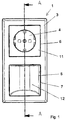
- the installation arrangement 1 is fastened to a building wall 2 and comprises a vertically aligned frame 3, as well as a first functional element 4 and a second functional element 5.
- the frame 3 is rectangular in shape and has two receiving openings 6 and 7 of identical shape, which are arranged one above the other.
- the first functional element 4 is arranged in the upper receiving opening 6, while the second functional element 5 is arranged in the lower receiving opening 7.
- the first functional element 4 is an electrical installation device that is part of an electrical supply network of a building or a room.
- the first functional element 4 is shown in the form of a socket.
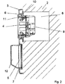
- the first functional element 4 is fixed in a mounting opening 8 in the building wall 2 and can be fastened in an installation housing, not shown in detail.
- the connection to the electrical supply network is made via lines (not shown) laid in the building wall 2.
- the first functional element has a device base 9, which is surrounded on the outside by a support frame 10, which enables the first functional element 4 to be fastened in the installation housing.
- a front element 11 is arranged on the front. The front element 11 is fastened to the device base 9 with the interposition of the frame 3. The frame 3 is thus adequately fixed and positioned in relation to the building wall 2. In the assembled state, the first functional element 4 is integrated flush in the frame 3.
- the second functional element 5 is not part of the electrical supply network and has mechanical functions.
- the second functional element 5 is formed at the front with a receiving chamber 12.
- many other functionalities for the second functional element 5 are also conceivable.
- the assembly of the second functional element 5 does not require any complex assembly work.
- the second functional element 5 is fastened in the receiving opening 7 on the surrounding frame 2, complementary latching means (not shown) ensuring a non-positive and / or positive locking.
- the second functional element 5 can additionally be screwed to the building wall 2, provided that the function of the second functional element 5 requires such a fastening, for example when the second functional element 5 is subjected to increased force by external devices.
- the second functional element 5 bears against the building wall 2.
- the second functional element 5 is integrated flush on the front in the frame 3.
- the installation arrangement 1 can be arranged in the kitchen or in the bathroom.
- the receiving chamber 12 of the second functional element 5 then serves, for example, to hold bathroom accessories such as scissors, cosmetic pencils or kitchen utensils such as Cutlery or pens.
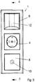
- FIG. 3 An alternative embodiment of the installation arrangement 1 is shown.
- a frame with three horizontally arranged functional elements is shown.
- a first functional element 4 is part of the electrical supply network and arranged centrally, while a second functional element 5 is arranged above and below the first functional element 4.
- the upper second functional element 5 has a receiving chamber 12 on the front.
- the lower second functional element 5 has a holder 13 in the form of a hook on the front, for example for towels, keys or other objects.
Landscapes
- Engineering & Computer Science (AREA)
- Architecture (AREA)
- Civil Engineering (AREA)
- Structural Engineering (AREA)
- Casings For Electric Apparatus (AREA)
- Mounting Components In General For Electric Apparatus (AREA)
- Supports Or Holders For Household Use (AREA)
Description
- Die Erfindung betrifft eine Installationsanordnung nach dem Oberbegriff des Patentanspruchs 1. Eine solche Installationsanordnung ist aus der
US 4 662 697 A bekannt. - Im Rahmen der Gebäudeinstallationstechnik werden elektrische Installationsgeräte dazu verwendet, elektrische Verbraucher mittels Steckdosen mit Energie zu versorgen und/oder mittels Schaltelementen die Energieversorgung von elektrischen Verbrauchern zu steuern. Die Installationsgeräte eines derartigen Versorgungsnetzes können ortsfest in einer Wand angeordnet sein und sind häufig von einem Rahmen umgeben. Abhängig von den örtlichen Gegebenheiten werden Installationsgeräte benachbart zueinander angeordnet, um platzsparende und optisch ansprechende Bedienstellen zu schaffen. Die Installationsgeräte werden horizontal oder vertikal nebeneinander angeordnet und von Rahmen mit einer entsprechenden Anzahl von Aufnahmeöffnungen umgeben. Die Abmessungen der Installationsgeräte und der Aufnahmeöffnungen in den Rahmen sind aufeinander abgestimmt, so dass bei unterschiedlichen und variablen Kombinationen von Installationsgeräten ein gleichbleibendes Design erhalten bleibt. Die bisher bekannten Lösungen weisen keine Möglichkeiten auf, um Funktionselemente außerhalb des elektrischen Versorgungsnetzes in ein derartiges Rahmenkonzept zu integrieren.
- Die Aufgabe der vorliegenden Erfindung besteht darin, eine variable Installationsanordnung zu schaffen, die alternative und zusätzliche Funktionalitäten ermöglicht und dabei montagefreundlich und optisch ansprechend ausgebildet ist.
- Gelöst wird diese Aufgabe durch die im Patentanspruch 1 angegebenen Merkmale. Vorteilhafte Ausgestaltungen ergeben sich aus der Beschreibung, den Zeichnungen und den Unteransprüchen.
- Die Erfindung gemäß dem Patentanspruch 1 weist den Vorteil auf, dass durch eine Integration von Funktionselementen außerhalb des elektrischen Versorgungsnetzes in eine elektrische Installationsanordnung zusätzliche Funktionen in einer zentralen Bedienstelle zusammengefasst werden können. Vorteilhafterweise lassen sich somit bisher separat angeordnete Komponenten mit nichtelektrischen, beispielsweise mechanischen, Funktionalitäten integrieren. Eine solche Anordnung spart Platz und ermöglicht ein einheitliches Erscheinungsbild trotz unterschiedlichster Anwendungen. Somit kann die bisherige Funktionalität von Installationsanordnungen deutlich verbessert werden.
- Durch die Integration solcher zweiter Funktionselemente kann eine bedarfsgerechte Anpassung und Umrüstung einer Installationsanordnung an zusätzliche Anforderungen am Montageort realisiert werden kann. Eine bestehende Installationsanordnung kann einfach zu einer multifunktionalen Bedienstelle aufgerüstet werden.
- Die Geometrie und die Struktur der zweiten Funktionselemente, der elektrischen Funktionselemente und der Rahmen sind aufeinander abgestimmt, so dass eine vollständige Kompatibilität geschaffen werden kann. Vorteilhaft ist dabei, dass im Falle einer Nachrüstung lediglich ein vorhandener Rahmen durch einen um eine Aufnahmeöffnung erweiterten Rahmen ausgetauscht und um das zweite Funktionselement ergänzt werden muss oder gegen ein zweites Funktionselement getauscht werden kann. Durch einheitliche Abmessungen und Strukturen können die Fertigungs-und Lagerkosten reduziert werden.
- Da das Funktionselement des elektrischen Versorgungsnetzes in einer Montageöffnung der Wand fixiert wird und der Rahmen zwischen Bestandteilen dieses Funktionselementes eingeklemmt oder aufgerastet wird, erfordert die Installation eines zweiten Funktionselementes keine aufwendigen Montagetätigkeiten.
- Je nach Ausführung und Funktion ist schon eine mechanische Verbindung in der entsprechenden Aufnahmeöffnung mit dem umgebenden Rahmen ausreichend, um das zweite Funktionselement zu befestigen. Dies kann kraft- und/oder formschlüssig erfolgen, wobei vorzugsweise komplementäre Rastmittel eingesetzt werden können. Das Funktionselement ist kann lösbar in der Installationsanordnung befestigt werden.
- In einer weiteren Ausführung kann eine Befestigung des zweiten Funktionselementes an der Wand erfolgen, beispielsweise bei erhöhter Krafteinwirkung auf das zweite Funktionselement durch externe Geräte. Dafür können sich beispielsweise schraubende oder klebende Befestigungen eignen. Vorteilhafterweise unterstützen komplementäre Rastmittel die Befestigung, so dass eine lagegenaue Positionierung in der Aufnahmeöffnung des Rahmens erfolgt. Eine große Montageöffnung in der Wand wie bei den Funktionselementen des elektrischen Versorgungsnetzes ist nicht erforderlich.
- Frontseitig kann das zweite Funktionselement bündig mit dem Rahmen abschließen, wobei es vorteilhafterweise optisch an das Design des Rahmens oder weiterer vorhandener Funktionselemente angepasst sein kann. Das Funktionselement kann ein adäquates Erscheinungsbild aufweisen.
- Die Anordnung der Funktionselemente orientiert sich an den örtlichen Gegebenheiten, jedoch insbesondere unter dem Aspekt einer Nichtbeeinflussung von Funktionen.
- Das zweite Funktionselement kann einteilig oder mehrteilig ausgebildet sein und als zentraler Einsatz in der Aufnahmeöffnung eines Mehrfach-Rahmens angeordnet sein. Das zweite Funktionselement kann eine in sich geschlossene Baugruppe bilden.
- In einer weiteren Ausgestaltung kann das zweite Funktionselement auswechselbare Elemente aufweisen, um dasselbe Funktionselement durch Umrüstung einzelner Elemente für andere Funktionen nutzen zu können. In einer vorteilhaften Ausgestaltung können zweite Funktionselemente durch austauschbare oder ergänzende Einsätze oder Vorsätze an unterschiedliche Anforderungen angepasst werden. Optional können komplementäre Rastmittel eine zusätzliche Fixierung von externen Geräten schaffen.
- Das zweite Funktionselement kann im Bad, in der Küche, im Büro, in der Werkstatt sowie in zahlreichen anderen Räumen angeordnet werden. Es können dabei beispielsweise Aufnahmekammern oder Halterungen für Badaccessoires, Küchenutensilien, Büromaterialien oder Werkzeuge ausgebildet werden.
- In einer weiteren Verwendung kann das zweite Funktionselement eine magnetische oder haftende Oberfläche aufweisen, so dass Gegenstände oder Zettel befestigt werden können.
- Vorteilhafte Anwendungsbereiche für zweite Funktionselemente können sich auch im Bereich der Darstellung von Informationen, beispielsweise visuelle und/oder akustische Informationen, ergeben. Unterschiedlich ausgestaltete zweite Funktionselemente können spezifische Anforderungen an die Darstellung der Informationen erfüllen. Beispielweise kann das zweite Funktionselement eine Uhr oder ein Thermometer aufweisen.
- In einer vorteilhaften Ausgestaltung können die zweiten Funktionselemente als mechanischer Adapter für externe Geräte dienen. Hierbei können komplementäre Einrichtungen am zweiten Funktionselement und am externen Gerät zusammenarbeiten, so dass eine stabile mechanische Kopplung gewährleistet werden kann.
- Weitere Einzelheiten, Merkmale und Vorteile der Erfindung ergeben sich aus nachfolgender Beschreibung eines bevorzugten Ausführungsbeispieles anhand der Zeichnungen.
- Es zeigen:
- Fig. 1
- eine Darstellung einer ersten schematisch dargestellten Installationsanordnung,
- Fig. 2
- einen Schnitt durch die Installationsanordnung nach
Figur 1 , - Fig. 3
- eine Darstellung einer weiteren Installationsanordnung, und
- Fig. 4
- einen Schnitt durch die Installationsanordnung nach
Figur 3 . - Gleiche oder gleichwirkende Bauteile sind in der nachfolgenden Beschreibung mit gleichen Bezugszeichen versehen.
- Nachfolgend wird der Aufbau und die Funktionsweise der erfindungsgemäßen Installationsanordnung 1 schematisch anhand von alternativen Ausführungsbeispielen näher beschrieben.
- Die Installationsanordnung 1 ist an einer Gebäudewand 2 befestigt und umfasst einen vertikal ausgerichteten Rahmen 3, sowie ein erstes Funktionselement 4 und ein zweites Funktionselement 5. Der Rahmen 3 ist rechteckig geformt und weist zwei gleich geformte Aufnahmeöffnungen 6 und 7 auf, die übereinander angeordnet sind. In der oberen Aufnahmeöffnung 6 ist das erste Funktionselement 4 angeordnet, während in der unteren Aufnahmeöffnung 7 das zweite Funktionselement 5 angeordnet ist.
- Das erste Funktionselement 4 ist ein elektrisches Installationsgerät, das Bestandteil eines elektrischen Versorgungsnetzes eines Gebäudes oder eines Raumes ist. In der
Figur 1 ist das erste Funktionselement 4 in Form einer Steckdose dargestellt. Es ist jedoch auch jedes andere elektrische Installationsgerät denkbar. Das erste Funktionselement 4 ist ortsfest in einer Montageöffnung 8 der Gebäudewand 2 fixiert und kann dabei in einem nicht näher dargestellten Installationsgehäuse befestigt werden. Der Anschluss an das elektrische Versorgungsnetz erfolgt über in der Gebäudewand 2 verlegte Leitungen (nicht dargestellt). - Das erste Funktionselement weist einen Gerätesockel 9 auf, den außenseitig ein Tragrahmen 10 umgibt, der die Befestigung des ersten Funktionselementes 4 in dem Installationsgehäuse ermöglicht. Frontseitig ist ein Frontelement 11 angeordnet. Das Frontelement 11 ist unter Zwischenlage des Rahmens 3 an dem Gerätesockel 9 befestigt. Der Rahmen 3 ist damit hinreichend gegenüber der Gebäudewand 2 fixiert und positioniert. Im montierten Zustand ist das erste Funktionselement 4 flächenbündig in den Rahmen 3 integriert.
- Das zweite Funktionselement 5 ist kein Bestandteil des elektrischen Versorgungsnetzes und hat mechanische Funktionen. In der
Figur 1 ist das zweite Funktionselement 5 frontseitig mit einer Aufnahmekammer 12 ausgebildet. Es sind jedoch auch viele weitere Funktionalitäten für das zweite Funktionselement 5 denkbar. Die Montage des zweiten Funktionselementes 5 erfordert keine aufwendigen Montagetätigkeiten. Das zweite Funktionselement 5 ist in der Aufnahmeöffnung 7 an dem umgebenden Rahmen 2 befestigt, wobei nicht dargestellte komplementäre Rastmittel eine kraft- und/oder formschlüssig Fixierung gewährleisten. Das zweite Funktionselement 5 kann zusätzlich schraubend an der Gebäudewand 2 befestigt werden, sofern die Funktion des zweiten Funktionselementes 5 eine derartige Befestigung erfordert, beispielsweise bei erhöhter Krafteinwirkung auf das zweite Funktionselement 5 durch externe Geräte. Rückseitig liegt das zweite Funktionselement 5 an der Gebäudewand 2 an. Im montierten Zustand ist das zweite Funktionselement 5 frontseitig flächenbündig in den Rahmen 3 integriert. - In der Ausgestaltung gemäß der
Figuren 1 und2 kann die Installationsanordnung 1 beispielsweise in der Küche oder im Bad angeordnet sein. Die Aufnahmekammer 12 des zweiten Funktionselementes 5 dient dann beispielsweise zur Aufnahme von Badaccesoires wie Scheren, Kosmetikstifte oder von Küchenutensilien wie Bestecke oder Stifte. - In der
Fig. 3 und in derFig. 4 ist eine alternative Ausführungsform der Installationsanordnung 1 dargestellt. InFigur 3 ist ein Rahmen mit drei horizontal angeordneten Funktionselementen dargestellt. Ein erstes Funktionselement 4 ist Bestandteil des elektrischen Versorgungsnetzes und mittig angeordnet, während je ein zweites Funktionselemente 5 oberhalb und unterhalb des ersten Funktionselementes 4 angeordnet ist. Das obere zweite Funktionselement 5 weist frontseitig eine Aufnahmekammer 12 auf. Das untere zweite Funktionselement 5 weist frontseitig eine Halterung 13 in Form eines Hakens auf, beispielsweise für Handtücher, Schlüssel oder sonstige Gegenstände. -
- 1
- Installationsanordnung
- 2
- Gebäudewand
- 3
- Rahmen
- 4
- erstes Funktionselement
- 5
- zweites Funktionselement
- 6
- Aufnahmeöffnung
- 7
- Aufnahmeöffnung
- 8
- Montageöffnung
- 9
- Gerätesockel
- 10
- Tragrahmen
- 11
- Frontelement
- 12
- Aufnahmekammer
- 13
- Halterung
Claims (5)
- Installationsanordnung umfassend einen Rahmen (3) mit mindestens zwei Aufnahmeöffnungen (6, 7), wobei in einer ersten Aufnahmeöffnung (6) ein erstes Funktionselement (4) angeordnet ist, das Bestandteil eines elektrischen und/oder optischen Versorgungsnetzes ist und das in einer Wand (2) befestigt ist, und wobei in einer zweiten Aufnahmeöffnung (7) ein zweites Funktionselement (5) angeordnet ist, das nicht Bestandteil eines elektrischen und/oder optischen Versorgungsnetzes ist, wobei die Aufnahmeöffnungen (6, 7) die gleichen Abmessungen aufweisen und das zweite Funktionselement (5) Mittel (12, 13) aufweist, um externe Gegenstände aufzunehmen oder um externe Geräte mechanisch zu koppeln,
dadurch gekennzeichnet, dass das zweite Funktionselement (5) an der Wand (2) aufliegend in dem Rahmen (3) anordenbar ist und frontseitig eine Halterung in Form eines Hakens (13) aufweist. - Installationsanordnung nach zumindest einem der vorhergehenden Patentansprüche, dadurch gekennzeichnet, dass das zweite Funktionselement (5) eine in sich geschlossene Baugruppe bildet.
- Installationsanordnung nach zumindest einem der vorhergehenden Patentansprüche, dadurch gekennzeichnet, dass das zweite Funktionselement (5) an dem Rahmen (3) und/oder an der Wand (2) befestigbar ist.
- Installationsanordnung nach zumindest einem der vorhergehenden Patentansprüche, dadurch gekennzeichnet, dass das zweite Funktionselement (5) lösbar an dem Rahmen (3) anordenbar ist.
- Installationsanordnung nach zumindest einem der vorhergehenden Patentansprüche, dadurch gekennzeichnet, dass das zweite Funktionselement (5) frontseitig flächenbündig zu dem umgebenden Rahmen (3) anordenbar ist.
Applications Claiming Priority (2)
| Application Number | Priority Date | Filing Date | Title |
|---|---|---|---|
| DE102011122494A DE102011122494A1 (de) | 2011-12-28 | 2011-12-28 | Installationsanordnung |
| PCT/EP2012/075238 WO2013098078A1 (de) | 2011-12-28 | 2012-12-12 | Installationsanordnung |
Publications (3)
| Publication Number | Publication Date |
|---|---|
| EP2777113A1 EP2777113A1 (de) | 2014-09-17 |
| EP2777113B1 EP2777113B1 (de) | 2017-09-06 |
| EP2777113B2 true EP2777113B2 (de) | 2020-05-27 |
Family
ID=47557028
Family Applications (1)
| Application Number | Title | Priority Date | Filing Date |
|---|---|---|---|
| EP12813782.5A Active EP2777113B2 (de) | 2011-12-28 | 2012-12-12 | Installationsanordnung |
Country Status (8)
| Country | Link |
|---|---|
| EP (1) | EP2777113B2 (de) |
| CN (1) | CN104170193B (de) |
| AU (1) | AU2012361167B2 (de) |
| BR (1) | BR112014016175B1 (de) |
| DE (1) | DE102011122494A1 (de) |
| ES (1) | ES2651127T5 (de) |
| RU (1) | RU2612401C2 (de) |
| WO (1) | WO2013098078A1 (de) |
Families Citing this family (2)
| Publication number | Priority date | Publication date | Assignee | Title |
|---|---|---|---|---|
| US9147973B1 (en) | 2013-09-11 | 2015-09-29 | Michael W. Madison | Enclosure for wall charger |
| USD817159S1 (en) | 2015-07-17 | 2018-05-08 | Curv Brands, Llc | Keychain hanger |
Citations (6)
| Publication number | Priority date | Publication date | Assignee | Title |
|---|---|---|---|---|
| DE1993994U (de) † | 1967-01-04 | 1968-09-19 | Schneider & Co Dr Ing | Kombinierte anschlusseinrichtung fuer verschiedenartige versorgungssysteme. |
| DE7144829U (de) † | 1971-11-29 | 1972-05-04 | Eberle Werke Kg | Schaltuhr |
| DE2432811A1 (de) † | 1974-07-09 | 1976-01-29 | Graesslin Feinwerktech | Synchronuhr mit elektrischer schalteinrichtung |
| DE7931905U1 (de) † | 1979-11-12 | 1980-02-21 | Dieter Graesslin Feinwerktechnik, 7742 St Georgen | Raumthermostatschaltuhr |
| US6130384A (en) † | 1997-06-03 | 2000-10-10 | Esteves; Antonio | Coverplate storage device |
| DE102009021449A1 (de) † | 2009-02-27 | 2010-09-09 | Abb Ag | Elektrisches Installationsgerät mit Ladegerät und Ablagemöglichkeit für Mobiltelefon |
Family Cites Families (7)
| Publication number | Priority date | Publication date | Assignee | Title |
|---|---|---|---|---|
| US3556455A (en) * | 1968-06-24 | 1971-01-19 | Fred Storm Ind Designs Inc | Overhead equipment control apparatus for operating rooms |
| US4662697A (en) * | 1986-05-20 | 1987-05-05 | Paul Moses | Safety device for electrical outlet |
| AT9548U1 (de) * | 2004-02-02 | 2007-11-15 | Moeller Gebaeudeautomation Kg | Elektro-installationseinheit |
| RU63126U1 (ru) * | 2006-12-19 | 2007-05-10 | Мария Владимировна Чеклецова | Люк для подвода кабелей |
| US20080272258A1 (en) * | 2007-05-04 | 2008-11-06 | Thomas Wysoczynski | Device for rechargeable electrical apparatus retainer unit |
| CN201438565U (zh) * | 2009-05-15 | 2010-04-14 | 廖生兴 | 可拆卸的插座面板结构 |
| CN201690176U (zh) * | 2010-06-08 | 2010-12-29 | 周廷洪 | 配电箱装饰柜 |
-
2011
- 2011-12-28 DE DE102011122494A patent/DE102011122494A1/de not_active Withdrawn
-
2012
- 2012-12-12 ES ES12813782T patent/ES2651127T5/es active Active
- 2012-12-12 AU AU2012361167A patent/AU2012361167B2/en active Active
- 2012-12-12 EP EP12813782.5A patent/EP2777113B2/de active Active
- 2012-12-12 CN CN201280070861.6A patent/CN104170193B/zh active Active
- 2012-12-12 WO PCT/EP2012/075238 patent/WO2013098078A1/de active Application Filing
- 2012-12-12 RU RU2014131018A patent/RU2612401C2/ru active
- 2012-12-12 BR BR112014016175-5A patent/BR112014016175B1/pt active IP Right Grant
Patent Citations (6)
| Publication number | Priority date | Publication date | Assignee | Title |
|---|---|---|---|---|
| DE1993994U (de) † | 1967-01-04 | 1968-09-19 | Schneider & Co Dr Ing | Kombinierte anschlusseinrichtung fuer verschiedenartige versorgungssysteme. |
| DE7144829U (de) † | 1971-11-29 | 1972-05-04 | Eberle Werke Kg | Schaltuhr |
| DE2432811A1 (de) † | 1974-07-09 | 1976-01-29 | Graesslin Feinwerktech | Synchronuhr mit elektrischer schalteinrichtung |
| DE7931905U1 (de) † | 1979-11-12 | 1980-02-21 | Dieter Graesslin Feinwerktechnik, 7742 St Georgen | Raumthermostatschaltuhr |
| US6130384A (en) † | 1997-06-03 | 2000-10-10 | Esteves; Antonio | Coverplate storage device |
| DE102009021449A1 (de) † | 2009-02-27 | 2010-09-09 | Abb Ag | Elektrisches Installationsgerät mit Ladegerät und Ablagemöglichkeit für Mobiltelefon |
Non-Patent Citations (2)
| Title |
|---|
| ANONYMOUS: "Katalog 1992", BUSCH-JAEGER GMBH ELEKTRO, [retrieved on 20180725] † |
| ANONYMOUS: "Katalog 2007", BUSCH-JAEGER GMBH ELEKTRO, [retrieved on 20180725] † |
Also Published As
| Publication number | Publication date |
|---|---|
| CN104170193B (zh) | 2018-01-12 |
| EP2777113A1 (de) | 2014-09-17 |
| RU2014131018A (ru) | 2016-02-20 |
| WO2013098078A1 (de) | 2013-07-04 |
| ES2651127T3 (es) | 2018-01-24 |
| RU2612401C2 (ru) | 2017-03-09 |
| CN104170193A (zh) | 2014-11-26 |
| BR112014016175B1 (pt) | 2020-10-27 |
| ES2651127T5 (es) | 2021-01-27 |
| DE102011122494A1 (de) | 2013-07-04 |
| BR112014016175A2 (pt) | 2017-06-13 |
| AU2012361167B2 (en) | 2016-05-19 |
| AU2012361167A1 (en) | 2014-07-10 |
| BR112014016175A8 (pt) | 2017-07-04 |
| EP2777113B1 (de) | 2017-09-06 |
Similar Documents
| Publication | Publication Date | Title |
|---|---|---|
| DE102009011904B4 (de) | Verbindungsvorrichtung | |
| DE102011053341B4 (de) | Elektrisches/elektronisches Gerät | |
| EP2042671B1 (de) | Vorrichtung zur sicheren Anbringung eines Griff-Betätigungsstiftes an einer Befestigungöffnung eines Griffs | |
| EP2777113B2 (de) | Installationsanordnung | |
| EP2007253A2 (de) | Möbel | |
| DE102010022470A1 (de) | Regalsystem | |
| DE202014105219U1 (de) | Erdungsschienenvorrichtung | |
| EP2930809B1 (de) | Elektrisches/elektronisches Installationsgerät | |
| DE202016101788U1 (de) | Universell einsetzbares Kabelgehäuse für Mini-PCs und dergleichen | |
| EP3453942B1 (de) | Wandhalter und befestigungsset | |
| DE102008001461A1 (de) | Befestigungssockel für Energiesäulen oder Stehleuchten | |
| DE102017006870A1 (de) | Elektrisches Installationsgerät | |
| EP2351176B1 (de) | Elektrisches installationsgerät | |
| EP1394915B1 (de) | Kabelführung | |
| DE102014110652B3 (de) | Elektrisches/elektronisches Installationsgerät | |
| DE202008006092U1 (de) | Befestigungssockel für Energiesäulen oder Stehleuchten | |
| DE102009020726A1 (de) | Versorgungssystem zum Bereitstellen einer Medienversorgung | |
| DE202016006067U1 (de) | Schalteinrichtung für Möbel | |
| DE8533097U1 (de) | Stromversorgungsgerät, insbesondere für Lehrzwecke | |
| DE102007004905A1 (de) | Befestigung eines elektrischen Geräts an einer Aufnahmeplatte, insbesondere an einer Schalttafel, sowie Adapter für eine solche Befestigung | |
| EP2706634B1 (de) | Elektrisches / elektronisches installationsgerät mit einem abdeckrahmen | |
| DE202012012436U1 (de) | Nachrüsteinrichtung für eine Kabeldurchführung einer Möbelplatte | |
| DE8403659U1 (de) | Unterputzinstallationsgerät für diverse Bauelemente, insbesondere für elektrische und/oder elektronische Befehlsorgane, Meldeorgane und/oder Steckverbinder | |
| EP1283665B1 (de) | Wandhalterung für ein elektrisches Gerät und elektrisches Gerät für eine solche Wandhalterung | |
| DE102012025520A1 (de) | Nachrüsteinrichtung für eine Kabeldurchführung einer Möbelplatte |
Legal Events
| Date | Code | Title | Description |
|---|---|---|---|
| PUAI | Public reference made under article 153(3) epc to a published international application that has entered the european phase |
Free format text: ORIGINAL CODE: 0009012 |
|
| 17P | Request for examination filed |
Effective date: 20140611 |
|
| AK | Designated contracting states |
Kind code of ref document: A1 Designated state(s): AL AT BE BG CH CY CZ DE DK EE ES FI FR GB GR HR HU IE IS IT LI LT LU LV MC MK MT NL NO PL PT RO RS SE SI SK SM TR |
|
| DAX | Request for extension of the european patent (deleted) | ||
| 17Q | First examination report despatched |
Effective date: 20160708 |
|
| GRAP | Despatch of communication of intention to grant a patent |
Free format text: ORIGINAL CODE: EPIDOSNIGR1 |
|
| INTG | Intention to grant announced |
Effective date: 20170322 |
|
| GRAS | Grant fee paid |
Free format text: ORIGINAL CODE: EPIDOSNIGR3 |
|
| GRAA | (expected) grant |
Free format text: ORIGINAL CODE: 0009210 |
|
| AK | Designated contracting states |
Kind code of ref document: B1 Designated state(s): AL AT BE BG CH CY CZ DE DK EE ES FI FR GB GR HR HU IE IS IT LI LT LU LV MC MK MT NL NO PL PT RO RS SE SI SK SM TR |
|
| REG | Reference to a national code |
Ref country code: GB Ref legal event code: FG4D Free format text: NOT ENGLISH |
|
| REG | Reference to a national code |
Ref country code: CH Ref legal event code: EP Ref country code: AT Ref legal event code: REF Ref document number: 926860 Country of ref document: AT Kind code of ref document: T Effective date: 20170915 |
|
| REG | Reference to a national code |
Ref country code: IE Ref legal event code: FG4D Free format text: LANGUAGE OF EP DOCUMENT: GERMAN |
|
| REG | Reference to a national code |
Ref country code: DE Ref legal event code: R096 Ref document number: 502012011233 Country of ref document: DE |
|
| REG | Reference to a national code |
Ref country code: FR Ref legal event code: PLFP Year of fee payment: 6 |
|
| REG | Reference to a national code |
Ref country code: SE Ref legal event code: TRGR |
|
| REG | Reference to a national code |
Ref country code: NL Ref legal event code: MP Effective date: 20170906 |
|
| REG | Reference to a national code |
Ref country code: ES Ref legal event code: FG2A Ref document number: 2651127 Country of ref document: ES Kind code of ref document: T3 Effective date: 20180124 |
|
| REG | Reference to a national code |
Ref country code: LT Ref legal event code: MG4D |
|
| PG25 | Lapsed in a contracting state [announced via postgrant information from national office to epo] |
Ref country code: FI Free format text: LAPSE BECAUSE OF FAILURE TO SUBMIT A TRANSLATION OF THE DESCRIPTION OR TO PAY THE FEE WITHIN THE PRESCRIBED TIME-LIMIT Effective date: 20170906 Ref country code: LT Free format text: LAPSE BECAUSE OF FAILURE TO SUBMIT A TRANSLATION OF THE DESCRIPTION OR TO PAY THE FEE WITHIN THE PRESCRIBED TIME-LIMIT Effective date: 20170906 Ref country code: HR Free format text: LAPSE BECAUSE OF FAILURE TO SUBMIT A TRANSLATION OF THE DESCRIPTION OR TO PAY THE FEE WITHIN THE PRESCRIBED TIME-LIMIT Effective date: 20170906 Ref country code: NO Free format text: LAPSE BECAUSE OF FAILURE TO SUBMIT A TRANSLATION OF THE DESCRIPTION OR TO PAY THE FEE WITHIN THE PRESCRIBED TIME-LIMIT Effective date: 20171206 |
|
| PG25 | Lapsed in a contracting state [announced via postgrant information from national office to epo] |
Ref country code: BG Free format text: LAPSE BECAUSE OF FAILURE TO SUBMIT A TRANSLATION OF THE DESCRIPTION OR TO PAY THE FEE WITHIN THE PRESCRIBED TIME-LIMIT Effective date: 20171206 Ref country code: LV Free format text: LAPSE BECAUSE OF FAILURE TO SUBMIT A TRANSLATION OF THE DESCRIPTION OR TO PAY THE FEE WITHIN THE PRESCRIBED TIME-LIMIT Effective date: 20170906 Ref country code: RS Free format text: LAPSE BECAUSE OF FAILURE TO SUBMIT A TRANSLATION OF THE DESCRIPTION OR TO PAY THE FEE WITHIN THE PRESCRIBED TIME-LIMIT Effective date: 20170906 |
|
| PG25 | Lapsed in a contracting state [announced via postgrant information from national office to epo] |
Ref country code: NL Free format text: LAPSE BECAUSE OF FAILURE TO SUBMIT A TRANSLATION OF THE DESCRIPTION OR TO PAY THE FEE WITHIN THE PRESCRIBED TIME-LIMIT Effective date: 20170906 |
|
| PG25 | Lapsed in a contracting state [announced via postgrant information from national office to epo] |
Ref country code: CZ Free format text: LAPSE BECAUSE OF FAILURE TO SUBMIT A TRANSLATION OF THE DESCRIPTION OR TO PAY THE FEE WITHIN THE PRESCRIBED TIME-LIMIT Effective date: 20170906 Ref country code: PL Free format text: LAPSE BECAUSE OF FAILURE TO SUBMIT A TRANSLATION OF THE DESCRIPTION OR TO PAY THE FEE WITHIN THE PRESCRIBED TIME-LIMIT Effective date: 20170906 Ref country code: RO Free format text: LAPSE BECAUSE OF FAILURE TO SUBMIT A TRANSLATION OF THE DESCRIPTION OR TO PAY THE FEE WITHIN THE PRESCRIBED TIME-LIMIT Effective date: 20170906 |
|
| REG | Reference to a national code |
Ref country code: DE Ref legal event code: R026 Ref document number: 502012011233 Country of ref document: DE |
|
| PG25 | Lapsed in a contracting state [announced via postgrant information from national office to epo] |
Ref country code: IS Free format text: LAPSE BECAUSE OF FAILURE TO SUBMIT A TRANSLATION OF THE DESCRIPTION OR TO PAY THE FEE WITHIN THE PRESCRIBED TIME-LIMIT Effective date: 20180106 Ref country code: SM Free format text: LAPSE BECAUSE OF FAILURE TO SUBMIT A TRANSLATION OF THE DESCRIPTION OR TO PAY THE FEE WITHIN THE PRESCRIBED TIME-LIMIT Effective date: 20170906 Ref country code: IT Free format text: LAPSE BECAUSE OF FAILURE TO SUBMIT A TRANSLATION OF THE DESCRIPTION OR TO PAY THE FEE WITHIN THE PRESCRIBED TIME-LIMIT Effective date: 20170906 Ref country code: EE Free format text: LAPSE BECAUSE OF FAILURE TO SUBMIT A TRANSLATION OF THE DESCRIPTION OR TO PAY THE FEE WITHIN THE PRESCRIBED TIME-LIMIT Effective date: 20170906 Ref country code: SK Free format text: LAPSE BECAUSE OF FAILURE TO SUBMIT A TRANSLATION OF THE DESCRIPTION OR TO PAY THE FEE WITHIN THE PRESCRIBED TIME-LIMIT Effective date: 20170906 |
|
| PLBI | Opposition filed |
Free format text: ORIGINAL CODE: 0009260 |
|
| PLAX | Notice of opposition and request to file observation + time limit sent |
Free format text: ORIGINAL CODE: EPIDOSNOBS2 |
|
| 26 | Opposition filed |
Opponent name: ABB AG Effective date: 20180530 |
|
| PG25 | Lapsed in a contracting state [announced via postgrant information from national office to epo] |
Ref country code: DK Free format text: LAPSE BECAUSE OF FAILURE TO SUBMIT A TRANSLATION OF THE DESCRIPTION OR TO PAY THE FEE WITHIN THE PRESCRIBED TIME-LIMIT Effective date: 20170906 |
|
| REG | Reference to a national code |
Ref country code: CH Ref legal event code: PL |
|
| GBPC | Gb: european patent ceased through non-payment of renewal fee |
Effective date: 20171212 |
|
| PG25 | Lapsed in a contracting state [announced via postgrant information from national office to epo] |
Ref country code: SI Free format text: LAPSE BECAUSE OF FAILURE TO SUBMIT A TRANSLATION OF THE DESCRIPTION OR TO PAY THE FEE WITHIN THE PRESCRIBED TIME-LIMIT Effective date: 20170906 |
|
| REG | Reference to a national code |
Ref country code: IE Ref legal event code: MM4A |
|
| PG25 | Lapsed in a contracting state [announced via postgrant information from national office to epo] |
Ref country code: LU Free format text: LAPSE BECAUSE OF NON-PAYMENT OF DUE FEES Effective date: 20171212 Ref country code: MT Free format text: LAPSE BECAUSE OF FAILURE TO SUBMIT A TRANSLATION OF THE DESCRIPTION OR TO PAY THE FEE WITHIN THE PRESCRIBED TIME-LIMIT Effective date: 20170906 |
|
| REG | Reference to a national code |
Ref country code: BE Ref legal event code: MM Effective date: 20171231 |
|
| PLBB | Reply of patent proprietor to notice(s) of opposition received |
Free format text: ORIGINAL CODE: EPIDOSNOBS3 |
|
| PG25 | Lapsed in a contracting state [announced via postgrant information from national office to epo] |
Ref country code: IE Free format text: LAPSE BECAUSE OF NON-PAYMENT OF DUE FEES Effective date: 20171212 |
|
| PG25 | Lapsed in a contracting state [announced via postgrant information from national office to epo] |
Ref country code: CH Free format text: LAPSE BECAUSE OF NON-PAYMENT OF DUE FEES Effective date: 20171231 Ref country code: LI Free format text: LAPSE BECAUSE OF NON-PAYMENT OF DUE FEES Effective date: 20171231 Ref country code: GB Free format text: LAPSE BECAUSE OF NON-PAYMENT OF DUE FEES Effective date: 20171212 Ref country code: BE Free format text: LAPSE BECAUSE OF NON-PAYMENT OF DUE FEES Effective date: 20171231 |
|
| REG | Reference to a national code |
Ref country code: AT Ref legal event code: MM01 Ref document number: 926860 Country of ref document: AT Kind code of ref document: T Effective date: 20171212 |
|
| PLAB | Opposition data, opponent's data or that of the opponent's representative modified |
Free format text: ORIGINAL CODE: 0009299OPPO |
|
| PG25 | Lapsed in a contracting state [announced via postgrant information from national office to epo] |
Ref country code: AT Free format text: LAPSE BECAUSE OF NON-PAYMENT OF DUE FEES Effective date: 20171212 |
|
| R26 | Opposition filed (corrected) |
Opponent name: ABB AG Effective date: 20180530 |
|
| PG25 | Lapsed in a contracting state [announced via postgrant information from national office to epo] |
Ref country code: MC Free format text: LAPSE BECAUSE OF FAILURE TO SUBMIT A TRANSLATION OF THE DESCRIPTION OR TO PAY THE FEE WITHIN THE PRESCRIBED TIME-LIMIT Effective date: 20170906 Ref country code: HU Free format text: LAPSE BECAUSE OF FAILURE TO SUBMIT A TRANSLATION OF THE DESCRIPTION OR TO PAY THE FEE WITHIN THE PRESCRIBED TIME-LIMIT; INVALID AB INITIO Effective date: 20121212 |
|
| APBM | Appeal reference recorded |
Free format text: ORIGINAL CODE: EPIDOSNREFNO |
|
| APBP | Date of receipt of notice of appeal recorded |
Free format text: ORIGINAL CODE: EPIDOSNNOA2O |
|
| PG25 | Lapsed in a contracting state [announced via postgrant information from national office to epo] |
Ref country code: CY Free format text: LAPSE BECAUSE OF NON-PAYMENT OF DUE FEES Effective date: 20170906 |
|
| APAH | Appeal reference modified |
Free format text: ORIGINAL CODE: EPIDOSCREFNO |
|
| PG25 | Lapsed in a contracting state [announced via postgrant information from national office to epo] |
Ref country code: MK Free format text: LAPSE BECAUSE OF FAILURE TO SUBMIT A TRANSLATION OF THE DESCRIPTION OR TO PAY THE FEE WITHIN THE PRESCRIBED TIME-LIMIT Effective date: 20170906 |
|
| APBU | Appeal procedure closed |
Free format text: ORIGINAL CODE: EPIDOSNNOA9O |
|
| PG25 | Lapsed in a contracting state [announced via postgrant information from national office to epo] |
Ref country code: TR Free format text: LAPSE BECAUSE OF FAILURE TO SUBMIT A TRANSLATION OF THE DESCRIPTION OR TO PAY THE FEE WITHIN THE PRESCRIBED TIME-LIMIT Effective date: 20170906 |
|
| PUAH | Patent maintained in amended form |
Free format text: ORIGINAL CODE: 0009272 |
|
| STAA | Information on the status of an ep patent application or granted ep patent |
Free format text: STATUS: PATENT MAINTAINED AS AMENDED |
|
| 27A | Patent maintained in amended form |
Effective date: 20200527 |
|
| AK | Designated contracting states |
Kind code of ref document: B2 Designated state(s): AL AT BE BG CH CY CZ DE DK EE ES FI FR GB GR HR HU IE IS IT LI LT LU LV MC MK MT NL NO PL PT RO RS SE SI SK SM TR |
|
| REG | Reference to a national code |
Ref country code: DE Ref legal event code: R102 Ref document number: 502012011233 Country of ref document: DE |
|
| PG25 | Lapsed in a contracting state [announced via postgrant information from national office to epo] |
Ref country code: PT Free format text: LAPSE BECAUSE OF FAILURE TO SUBMIT A TRANSLATION OF THE DESCRIPTION OR TO PAY THE FEE WITHIN THE PRESCRIBED TIME-LIMIT Effective date: 20170906 |
|
| PG25 | Lapsed in a contracting state [announced via postgrant information from national office to epo] |
Ref country code: GR Free format text: LAPSE BECAUSE OF FAILURE TO SUBMIT A TRANSLATION OF THE DESCRIPTION OR TO PAY THE FEE WITHIN THE PRESCRIBED TIME-LIMIT Effective date: 20170906 |
|
| PG25 | Lapsed in a contracting state [announced via postgrant information from national office to epo] |
Ref country code: AL Free format text: LAPSE BECAUSE OF FAILURE TO SUBMIT A TRANSLATION OF THE DESCRIPTION OR TO PAY THE FEE WITHIN THE PRESCRIBED TIME-LIMIT Effective date: 20170906 |
|
| REG | Reference to a national code |
Ref country code: SE Ref legal event code: RPEO |
|
| REG | Reference to a national code |
Ref country code: ES Ref legal event code: DC2A Ref document number: 2651127 Country of ref document: ES Kind code of ref document: T5 Effective date: 20210127 |
|
| P01 | Opt-out of the competence of the unified patent court (upc) registered |
Effective date: 20230803 |
|
| PGFP | Annual fee paid to national office [announced via postgrant information from national office to epo] |
Ref country code: SE Payment date: 20231110 Year of fee payment: 12 Ref country code: FR Payment date: 20231108 Year of fee payment: 12 Ref country code: DE Payment date: 20231031 Year of fee payment: 12 |
|
| PGFP | Annual fee paid to national office [announced via postgrant information from national office to epo] |
Ref country code: ES Payment date: 20240115 Year of fee payment: 12 |