EP2776723B1 - Axialverbindung - Google Patents
Axialverbindung Download PDFInfo
- Publication number
- EP2776723B1 EP2776723B1 EP12788415.3A EP12788415A EP2776723B1 EP 2776723 B1 EP2776723 B1 EP 2776723B1 EP 12788415 A EP12788415 A EP 12788415A EP 2776723 B1 EP2776723 B1 EP 2776723B1
- Authority
- EP
- European Patent Office
- Prior art keywords
- core element
- axial connection
- subcomponents
- shell
- contact surface
- Prior art date
- Legal status (The legal status is an assumption and is not a legal conclusion. Google has not performed a legal analysis and makes no representation as to the accuracy of the status listed.)
- Active
Links
Images


Classifications
-
- F—MECHANICAL ENGINEERING; LIGHTING; HEATING; WEAPONS; BLASTING
- F16—ENGINEERING ELEMENTS AND UNITS; GENERAL MEASURES FOR PRODUCING AND MAINTAINING EFFECTIVE FUNCTIONING OF MACHINES OR INSTALLATIONS; THERMAL INSULATION IN GENERAL
- F16C—SHAFTS; FLEXIBLE SHAFTS; ELEMENTS OR CRANKSHAFT MECHANISMS; ROTARY BODIES OTHER THAN GEARING ELEMENTS; BEARINGS
- F16C23/00—Bearings for exclusively rotary movement adjustable for aligning or positioning
- F16C23/02—Sliding-contact bearings
- F16C23/04—Sliding-contact bearings self-adjusting
- F16C23/043—Sliding-contact bearings self-adjusting with spherical surfaces, e.g. spherical plain bearings
-
- F—MECHANICAL ENGINEERING; LIGHTING; HEATING; WEAPONS; BLASTING
- F16—ENGINEERING ELEMENTS AND UNITS; GENERAL MEASURES FOR PRODUCING AND MAINTAINING EFFECTIVE FUNCTIONING OF MACHINES OR INSTALLATIONS; THERMAL INSULATION IN GENERAL
- F16C—SHAFTS; FLEXIBLE SHAFTS; ELEMENTS OR CRANKSHAFT MECHANISMS; ROTARY BODIES OTHER THAN GEARING ELEMENTS; BEARINGS
- F16C11/00—Pivots; Pivotal connections
- F16C11/04—Pivotal connections
- F16C11/06—Ball-joints; Other joints having more than one degree of angular freedom, i.e. universal joints
- F16C11/0604—Construction of the male part
- F16C11/0609—Construction of the male part made from two or more parts
-
- F—MECHANICAL ENGINEERING; LIGHTING; HEATING; WEAPONS; BLASTING
- F16—ENGINEERING ELEMENTS AND UNITS; GENERAL MEASURES FOR PRODUCING AND MAINTAINING EFFECTIVE FUNCTIONING OF MACHINES OR INSTALLATIONS; THERMAL INSULATION IN GENERAL
- F16C—SHAFTS; FLEXIBLE SHAFTS; ELEMENTS OR CRANKSHAFT MECHANISMS; ROTARY BODIES OTHER THAN GEARING ELEMENTS; BEARINGS
- F16C11/00—Pivots; Pivotal connections
- F16C11/04—Pivotal connections
- F16C11/06—Ball-joints; Other joints having more than one degree of angular freedom, i.e. universal joints
- F16C11/0614—Ball-joints; Other joints having more than one degree of angular freedom, i.e. universal joints the female part of the joint being open on two sides
-
- F—MECHANICAL ENGINEERING; LIGHTING; HEATING; WEAPONS; BLASTING
- F16—ENGINEERING ELEMENTS AND UNITS; GENERAL MEASURES FOR PRODUCING AND MAINTAINING EFFECTIVE FUNCTIONING OF MACHINES OR INSTALLATIONS; THERMAL INSULATION IN GENERAL
- F16C—SHAFTS; FLEXIBLE SHAFTS; ELEMENTS OR CRANKSHAFT MECHANISMS; ROTARY BODIES OTHER THAN GEARING ELEMENTS; BEARINGS
- F16C43/00—Assembling bearings
- F16C43/02—Assembling sliding-contact bearings
-
- F—MECHANICAL ENGINEERING; LIGHTING; HEATING; WEAPONS; BLASTING
- F16—ENGINEERING ELEMENTS AND UNITS; GENERAL MEASURES FOR PRODUCING AND MAINTAINING EFFECTIVE FUNCTIONING OF MACHINES OR INSTALLATIONS; THERMAL INSULATION IN GENERAL
- F16C—SHAFTS; FLEXIBLE SHAFTS; ELEMENTS OR CRANKSHAFT MECHANISMS; ROTARY BODIES OTHER THAN GEARING ELEMENTS; BEARINGS
- F16C2322/00—Apparatus used in shaping articles
- F16C2322/39—General build up of machine tools, e.g. spindles, slides, actuators
-
- F—MECHANICAL ENGINEERING; LIGHTING; HEATING; WEAPONS; BLASTING
- F16—ENGINEERING ELEMENTS AND UNITS; GENERAL MEASURES FOR PRODUCING AND MAINTAINING EFFECTIVE FUNCTIONING OF MACHINES OR INSTALLATIONS; THERMAL INSULATION IN GENERAL
- F16C—SHAFTS; FLEXIBLE SHAFTS; ELEMENTS OR CRANKSHAFT MECHANISMS; ROTARY BODIES OTHER THAN GEARING ELEMENTS; BEARINGS
- F16C2326/00—Articles relating to transporting
- F16C2326/20—Land vehicles
- F16C2326/24—Steering systems, e.g. steering rods or columns
Definitions
- the invention relates to an axial connection with a pivoting range according to the preamble of claim 1.
- Known axial connections are bolted connections, which enable a transmission of axial forces and a pivoting about the axis of the bolt.
- the disadvantage here is that only a pivoting about an axis is possible.
- an axial connector with a multi-part core element is known, which parts can be introduced separately into the shell and assembled there to form the core element.
- the object of the invention is to provide an axial connection of the type mentioned, with which the mentioned disadvantages can be avoided, with which a high mobility can be achieved with the sleeves can be stored and which allows a compact design.
- the shell element can be machined and easily incorporated into complex construction elements. In particular, a machining can be provided.
- the Fig. 1 to 18 show an axial connection 1 with a pivoting area, comprising a shell element 2 and at least partially in the shell element 2 arranged core element 3, wherein at least partially formed as a spherical surface contact surface 31 of the core element 3 in operative contact with an at least partially opposite to the contact surface 31 of the core element 3 formed Contact surface 21 of the shell element 2 is.
- the core element 3 is formed in two parts from subelements 4, 5 and the shell element 2 has an insertion recess 22 for insertion of the subelements 4, 5.
- axial connection 1 two components can be connected in such a way that on the one hand axial forces can be transmitted and on the other hand a swiveling movement of the components can take place.
- the axial forces are transmitted between the contact surface 31 of the core element 3 and the contact surface 21 of the shell element 2.
- axial forces and radial forces can be transmitted in this way.
- bending moments can be reduced by pivoting the components, whereby the stresses of the components can be kept low.
- the pivoting can be done in any direction. During pivoting, there is a sliding movement of the contact surface 31 of the core element 3 relative to the contact surface 21 of the shell element 2.
- the core element 3 is composed of two subelements 4, 5.
- the sub-elements 4, 5 are introduced individually into the shell element 2 and assembled to the core element 3.
- the core element 3 can essentially have the shape of a sphere in which ball caps have been removed on opposite sides.
- the core element 3 may have opposite end faces 33, which are substantially parallel to one another. At the end faces 33, a component can easily attack and 4.5 clamp the sub-elements against each other.
- the core element 3 is formed in two parts, thereby both the assembly of the core element 3 can be ensured in the shell element 2, and the number of items are kept low. Furthermore, a favorable power flow can be achieved by a small number of subelements 4, 5.
- the shell element 2 can be easily formed in a block-shaped region of a component, for example in a sheet metal part.
- two substantially parallel end faces 23 of the shell element 2 can be predetermined by the component, between which a recess for the arrangement of the core element 3 is formed.
- the axial connection 1 can be formed without further required forming processes or machining reworks. In this case, the axial connection can be easily made during assembly and disassembled in particular during maintenance and any defective parts to be renewed.
- the core element 3 is divided along a circumferential main circle, in particular along a main plane, the spherical surface of the contact surface 31.
- the insertion recess 22 can be made particularly small, whereby a particularly high load capacity of the axial connection 1 can be ensured.
- the cross section of the passage opening 32 may be round, wherein a straight and round passage opening 32 can be made particularly simple. An improved security against rotation of the component relative to the core element 3 can be achieved if the passage opening 32 has a different shape from a circle, for example, additionally a tongue and groove connection is provided or the passage opening 32 has an elliptical or polygonal cross section.
- the through-opening 32 of at least one of the sub-elements 4, 5 can have an internal thread, as a result of which a diametrically opposite pin element with an external thread can be screwed to the core element 3.
- the passage opening 32 is conical. It can be stretched on a conical area of a component.
- the sub-elements 4.5 comprise a fastening device for detachably connecting the sub-elements to one another.
- the fastening device can represent, for example, a screw fastening. It can also be provided that the fastening device is designed as a tongue and groove connection.
- the mobility of the core element 3 relative to the shell element 2 can be increased by the contact surface 21 of the bearing shell 2 and / or the contact surface 31 of the core element 3 have a friction-reducing coating.
- Both the shell element 2 and the sub-elements 4.5 can be easily formed by machine, in which case they can be configured in particular as a turned / milled parts. As a result, unwanted deformations or stresses in the elements 2,3,4,5 can be avoided. Furthermore, the elements 2,3,4,5 can be made very precisely, whereby a pivotal movement of the axial connection 1 is possible even with a large stress in the axial direction.
- the core member 3 is twisted in the shell member 2 so that the collision line of the subelements 4, 5 which is on the surface of the core member 3 is completely disposed in the shell member 2 and in contact with a contact surface 21 of the shell member 2.
- the crash line is formed by the edges of the sub-elements 4, 5 which are arranged in the core element 3 adjacent to another of the sub-elements 4, 5. These areas can be protected in the shell element 2 from contamination, with a long life of the axial connection can be achieved.
- a piston bottom 75 connected to the cylinder 7 is arranged adjacent to the cylinder bottom 73, in which the piston rod 81 can slide.
- the piston head 75 can be ensured that fluid from the fluid chamber 71 can not get into the sleeve 72.
- the piston head 75 can be connected by means of a fixing screw with the cylinder jacket 74 and / or the cylinder bottom 73.
- a Aufsteckteil 91 On the sleeve 72, a Tarsteckteil 91 may be arranged, which in the embodiment according to the FIGS. 19 and 20 has a cone-shaped outer surface and a threaded portion.
- the axial connection 1 with a conical through-opening 32 can be pushed onto the conical outer surface and braced with a nut element 92.
- the axial connection 1 By the force applied by the nut member 92 on the axial connection 1 force the axial connection 1 can be fixed with the Aufsteckteil on the sleeve 72.
- the advantage here is that the axial connection 1 can be fixed at any point of the sleeve 72.
- the sleeve 72 has a threaded portion 76 and a stop 77.
- the axial connection 1 can be pushed with a straight passage opening 32 on the sleeve 72 and braced with the nut member 92.
- the position of the axial connection 1 is determined by the position of the stop 77.
- the piston rod 81 is movably arranged in the axial connection 1 and pivoting about a pivot point which substantially coincides with the axis of the piston rod 81 is made possible. Furthermore, a pivoting about each normal to the axis of the piston rod rotation axis is possible. It can be ensured that the piston rod can always align between the engagement region 82 of the piston rod 81 and the axial connection 1 and unwanted bending stresses of the hydraulic cylinder 6 can be avoided. This ensures a long life and reliability of the system.
Description
- Die Erfindung betrifft eine Axialverbindung mit einem Schwenkbereich gemäß dem Oberbegriff des Patentanspruches 1.
- Bekannte Axialverbindungen sind Bolzen-Steckverbindungen, welche eine Übertragung von Axialkräften und eine Verschwenkung um die Achse des Bolzens ermöglichen. Nachteilig dabei ist, dass lediglich eine Verschwenkung um eine Achse möglich ist.
- Aus der
US 5 219 231 A , derUS 5 762 424 A , derUS 2004/022464 A1 , derUS 2 312 648 A und derUS 4 251 122 A sind Axialverbinder bekannt, welche um zwei Achsen verschwenkbar sind. - Aus der
DE 660 407 C ist ein Axialverbinder mit einem mehrteiligen Kernelement bekannt, welche Teile separat in die Schale eingeführt und dort zu dem Kernelement zusammengefügt werden können. - Aufgabe der Erfindung ist es eine Axialverbindung der eingangs genannten Art anzugeben, mit welcher die genannten Nachteile vermieden werden können, mit welcher eine hohe Bewegbarkeit erreicht werden kann, mit der auch Hülsen gelagert werden können und das eine kompakte Bauform ermöglicht.
- Erfindungsgemäß wird dies durch die Merkmale des Patentanspruches 1 erreicht.
- Dadurch ergibt sich der Vorteil, dass die Axialverbindung einfach als lösbare Verbindung bereitgestellt werden kann. Das Schalenelement kann maschinell gefertigt werden und einfach in komplexe Konstruktionselemente eingebracht werden. Insbesondere kann eine spanende Bearbeitung vorgesehen sein.
- Die Unteransprüche betreffen weitere vorteilhafte Ausgestaltungen der Erfindung.
- Ausdrücklich wird hiermit auf den Wortlaut der Patentansprüche Bezug genommen, wodurch die Ansprüche an dieser Stelle durch Bezugnahme in die Beschreibung eingefügt sind und als wörtlich wiedergegeben gelten.
- Die Erfindung wird unter Bezugnahme auf die beigeschlossenen Zeichnungen, in welchen lediglich bevorzugte Ausführungsformen beispielhaft dargestellt sind, näher beschrieben. Dabei zeigt:
-
Fig. 1 eine Ausführungsform einer Axialverbindung in axonometrischer Darstellung; -
Fig. 2 die Axialverbindung gemäßFig. 1 in Seitenansicht; -
Fig. 3 die Axialverbindung gemäßFig. 1 in Draufsicht; -
Fig. 4 bis 15 Zwischenschritte beim Zusammenbau der Axialverbindung gemäßFig. 1 , jeweils in axonometrischer Darstellung, Draufsicht und Seitenansicht; -
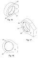
Fig. 16 und 17 jeweils axonometrische Darstellungen des Schalenelementes der Axialverbindung nachFig. 1 ; -
Fig. 18 eine Seitenansicht des Schalenelementes nachFig. 16 und 17 ; -
Fig. 19 und 20 eine Ausführungsform eines mit einer Axialverbindung mit konischer Durchgangsöffnung gelagerten Gleichgangszylinders, einmal in Draufsicht und einmal im Schnitt gemäß den Zeichen BB; und -
Fig. 21 und 22 eine Ausführungsform eines mit einer Axialverbindung mit gerader Durchgangsöffnung gelagerten Gleichgangszylinders, einmal in Draufsicht und einmal im Schnitt gemäß den Zeichen BB. - Die
Fig. 1 bis 18 zeigen eine Axialverbindung 1 mit einem Schwenkbereich, umfassend ein Schalenelement 2 und ein zumindest bereichsweise in dem Schalenelement 2 angeordneten Kernelement 3, wobei eine zumindest bereichsweise als Kugelfläche ausgebildete Kontaktfläche 31 des Kernelementes 3 in Wirkkontakt mit einer zumindest bereichsweise gegengleich zur Kontaktfläche 31 des Kernelementes 3 ausgebildeten Kontaktfläche 21 des Schalenelementes 2 ist. - Das Kernelement 3 ist zweiteilig aus Teilelementen 4,5 ausgebildet und das Schalenelement 2 weist eine Einführausnehmung 22 zum Einführen der Teilelemente 4,5 auf.
- Mit der Axialverbindung 1 können zwei Bauteile derart verbunden werden, dass einerseits Axialkräfte übertragen werden können und andererseits eine Verschwenkbewegung der Bauteile erfolgen kann. Die Axialkräfte werden zwischen der Kontaktfläche 31 des Kernelementes 3 und der Kontaktfläche 21 des Schalenelementes 2 übertragen. Neben Axialkräften können auch Radialkräfte auf diese Weise übertragen werden. Demgegenüber können Biegemomente durch eine Verschwenkung der Bauteile abgebaut werden, wodurch die Beanspruchungen der Bauteile gering gehalten werden können. Durch die als Kugelfläche ausgebildete Kontaktfläche 31 des Kernelementes 3 kann die Verschwenkung in jede Richtung erfolgen. Bei der Verschwenkung findet eine Gleitbewegung der Kontaktfläche 31 des Kernelementes 3 gegenüber der Kontaktfläche 21 des Schalenelementes 2 statt.
- Das Kernelement 3 ist aus zwei Teilelementen 4,5 zusammengesetzt.
- Dabei werden die Teilelemente 4,5 einzeln in das Schalenelement 2 eingebracht und zu dem Kernelement 3 zusammengesetzt.
- Das Kernelement 3 kann im Wesentlichen die Form einer Kugel aufweisen, bei der an gegenüberliegenden Seiten Kugelkappen entfernt wurden. Dabei kann das Kernelement 3 gegenüberliegende Stirnflächen 33 aufweisen, welche im Wesentlichen parallel zueinander sind. An den Stirnflächen 33 kann ein Bauteil einfach angreifen und die Teilelemente 4,5 gegeneinander verspannen.
- Das Kernelement 3 ist zweiteilig ausgebildet, hierdurch können sowohl der Zusammenbau des Kernelementes 3 in dem Schalenelement 2 sichergestellt werden, als auch die Anzahl der Einzelteile gering gehalten werden. Weiters kann ein günstiger Kraftfluss durch eine geringe Anzahl an Teilelementen 4,5 erreicht werden.
- Das Schalenelement 2 kann einfach in einem blockförmigen Bereich eines Bauteiles ausgebildet sein, beispielsweise in einem Blechteil. Dabei können durch den Bauteil zwei im Wesentlichen parallele Stirnseiten 23 des Schalenelementes 2 vorgeben werden, zwischen denen eine Ausnehmung für die Anordnung des Kernelementes 3 ausgebildet wird. Nach Ausbildung der Ausnehmung mit der Kontaktfläche 21 und der Einführausnehmung 22 kann die Axialverbindung 1 ohne weitere erforderliche Umformprozesse oder spanende Nachbearbeitungen gebildet werden. Dabei kann die Axialverbindung einfach bei der Montage hergestellt werden und insbesondere bei einer Wartung auseinandergebaut und allfällige schadhafte Teile erneuert werden.
- Das Kernelement 3 ist entlang eines umlaufenden Hauptkreises, insbesondere entlang einer Hauptebene, der Kugelfläche der Kontaktfläche 31 geteilt.
- Bei zwei Teilelementen 4,5 können diese vorzugsweise im Wesentlichen symmetrisch ausgebildet sein. Dabei kann die Einführausnehmung 22 besonders klein ausgebildet werden, wodurch eine besonders hohe Belastbarkeit der Axialverbindung 1 sichergestellt werden kann.
- Zur Anbindung des Kernelementes 3 an ein Bauteil kann vorgesehen sein, dass das Kernelement 3 eine Durchgangsöffnung 32 aufweist. Durch die Durchgangsöffnung 32 kann einfach ein Teil eines Bauteils geführt und mit dem Kernelement 3 verbunden werden. Dabei kann das Bauteil eine durch die Durchgangsöffnung 32 geführte Achse umfassen Mittels an zumindest eine der Stirnflächen 33 angreifende Spannelemente kann das Bauteil mit den Teilelementen 4,5 verspannt und so eine zuverlässige Verbindung erreicht werden.
- Der Querschnitt der Durchgangsöffnung 32 kann rund ausgebildet sein, wobei eine gerades und rundes Durchgangsöffnung 32 besonders einfach hergestellt werden kann. Eine verbesserte Verdrehsicherheit des Bauteils gegenüber dem Kernelement 3 kann erzielt werden, wenn die Durchgangsöffnung 32 eine von einem Kreis abweichende Form aufweist, beispielsweise zusätzlich eine Nut-Feder-Verbindung vorgesehen ist oder die Durchgangsöffnung 32 einen elliptischen oder polygonalen Querschnitt aufweist.
- Die Durchgangsöffnung 32 zumindest eines der Teilelemente 4,5 kann ein Innengewinde aufweisen, wodurch ein gegengleiches Zapfenelement mit einem Außengewinde mit dem Kernelement 3 verschraubt werden kann.
- Als besonders günstig hat sich herausgestellt, wenn die Durchgangsöffnung 32 konisch ausgebildet ist. Dabei kann sie auf einen kegelförmigen Bereich eines Bauteils gespannt werden.
- Weiters kann vorgesehen sein, dass die Teilelemente 4,5 eine Befestigungseinrichtung zum lösbaren Verbinden der Teilelemente untereinander umfassen. Durch die Befestigungseinrichtung kann eine Relativbewegung der Teilelemente 4,5 untereinander vermieden werden. Die Befestigungseinrichtung kann beispielsweise eine Schraubbefestigung darstellen. Es kann auch vorgesehen sein, dass die Befestigungseinrichtung als Nut-Feder-Verbindung ausgebildet ist.
- Die Bewegbarkeit des Kernelementes 3 gegenüber dem Schalenelement 2 kann erhöht werden, indem die Kontaktfläche 21 der Lagerschale 2 und/oder die Kontaktfläche 31 des Kernelementes 3 eine reibungsvermindernde Beschichtung aufweisen.
- Sowohl das Schalenelement 2 als auch die Teilelemente 4,5 können einfach maschinell ausgebildet werden, wobei sie insbesondere als Dreh-/Frästeile ausgestaltet werden können. Dadurch können ungewollte Verformungen oder Spannungen in den Elementen 2,3,4,5 vermieden werden. Weiters können die Elemente 2,3,4,5 besonders präzise gefertigt werden, wodurch eine Schwenkbewegung der Axialverbindung 1 auch bei einer großen Beanspruchung in axialer Richtung möglich ist.
- Die Axialverbindung 1 kann einfach hergestellt werden, indem eines der Teilelemente 4,5 des Kernelementes 3 über die Einführausnehmung 22 in das Schalenelement 2 eingebracht wird, anschließend das Teilelement 4,5 in dem Schalenelement 2 zur Freigabe der Einführausnehmung 22 verdreht wird, und nachfolgend ein weiteres der Teilelemente 4,5 des Kernelementes 3 über die Einführausnehmung 22 in das Schalenelement 2 eingebracht und das Kernelement 3 zusammengesetzt wird. Dieses Verfahren ist in den
Fig. 4 bis 15 dargestellt. - Das Kernelement 3 wird in dem Schalenelement 2 so verdreht, dass die Zusammenstoßlinie der Teilelemente 4,5, welche an der Oberfläche des Kernelementes 3 ist, vollständig in dem Schalenelement 2 angeordnet ist und mit einer Kontaktfläche 21 des Schalenelementes 2 in Kontakt ist. Die Zusammenstoßlinie wird durch die Kanten der Teilelemente 4,5 gebildet, welche in dem Kernelement 3 angrenzend an ein anderes der Teilelemente 4,5 angeordnet sind. Diese Bereiche können in dem Schalenelement 2 vor Verschmutzung geschützt werden, wobei eine lange Lebensdauer der Axialverbindung erreicht werden kann.
- Verwendung einer Axialverbindung 1 nach einem der Ansprüche 1 bis 9 zur Lagerung eines Hydraulikzylinders 6 einer Fahrzeuganhänger-Zwangslenkung.
- In den
Fig. 19 bis 22 ist ein Hydraulikzylinder 6 dargestellt, dessen Zylinder 7 mit einer Axialverbindung 1 gelagert ist. Der Hydraulikzylinder 6 ist als Gleichgangzylinder ausgebildet. Bei dem Gleichgangzylinder 6 ist auf beiden Seiten des Kolbens 8 eine Kolbenstange 81 angeordnet, sodass die Wirkfläche für das im Zylinder 7 befindliche Fluid auf beiden Seiten des Kolbens 8 gleich groß ist. - Der Zylinder 7 weist einen Fluidraum 71 auf, in dem der Kolben bewegbar angeordnet ist. Anschließend an den Fluidraum 71 ist eine Hülse 72 angeordnet, in welcher die Kolbenstange 81 bewegbar ist. Die Hülse 72 ist mit einem Zylinderboden 73 verbunden, welcher mit einem Zylindermantel 74 des Fluidraumes 71 verbunden ist. Diese Verbindungen können insbesondere durch Schweißnähte gebildet sein.
- In dem Fluidraum 71 ist angrenzend an den Zylinderboden 73 ein mit dem Zylinder 7 verbundener Kolbenboden 75 angeordnet, in welchem die Kolbenstange 81 gleiten kann. Mit diesem Kolbenboden 75 kann sichergestellt werden, dass Fluid aus dem Fluidraum 71 nicht in die Hülse 72 gelangen kann. Der Kolbenboden 75 kann mittels einer Fixierschraube mit dem Zylindermantel 74 und/oder dem Zylinderboden 73 verbunden sein.
- Auf der Hülse 72 kann ein Aufsteckteil 91 angeordnet sein, welches bei der Ausführung gemäß den
Fig. 19 und 20 eine konusförmige Außenoberfläche und einen Gewindeabschnitt aufweist. Die Axialverbindung 1 mit einer konusförmigen Durchgangsöffnung 32 kann auf die konusförmige Außenoberfläche aufgeschoben und mit einem Mutterelement 92 verspannt werden. Durch die von dem Mutterelement 92 auf die Axialverbindung 1 aufgebrachte Kraft kann die Axialverbindung 1 mit dem Aufsteckteil auf der Hülse 72 fixiert werden. Vorteilhaft dabei ist, dass die Axialverbindung 1 an jeder Stelle der Hülse 72 fixiert werden kann. - Bei der Ausführungsform gemäß den
Fig. 21 und 22 weist die Hülse 72 ein Gewindeteil 76 und einen Anschlag 77 auf. Dabei kann die Axialverbindung 1 mit einer geraden Durchgangsöffnung 32 auf die Hülse 72 aufgeschoben werden und mit dem Mutterelement 92 verspannt werden. Dabei wird die Lage der Axialverbindung 1 von der Position des Anschlags 77 bestimmt. - Durch die Ausbildung der Hülse 72 kann der erforderliche Abstand zwischen dem Angriffsbereich 82 der Kolbenstange 81 und der Lagerung des Zylinders 7 gering gehalten werden, sodass bei einer vorgegebenen Verschublänge der Kolbenstange 81 eine kompakte Bauform erreicht werden kann. An dem Angriffsbereich 82 der Kolbenstange 81 können weitere Bauteile mit der Kolbenstange 81 verbunden werden.
- Weiters kann mit der Axialverbindung 1 sichergestellt werden, dass die Kolbenstange 81 in der Axialverbindung 1 beweglich angeordnet ist und eine Verschwenkung um einen Drehpunkt, der im Wesentlichen mit der Achse der Kolbenstange 81 zusammenfällt, ermöglicht ist. Weiters ist eine Verschwenkung um jede zur Achse der Kolbenstange normale Drehachse möglich. Dabei kann sichergestellt werden, dass sich die Kolbenstange immer zwischen dem Angriffsbereich 82 der Kolbenstange 81 und der Axialverbindung 1 ausrichten kann und unerwünschte Biegebeanspruchungen des Hydraulikzylinders 6 vermieden werden. Dadurch kann eine hohe Lebensdauer und Zuverlässigkeit des Systems sichergestellt werden.
Claims (12)
- Axialverbindung (1) mit einem Schwenkbereich, umfassend ein Schalenelement (2) und ein zumindest bereichsweise in dem Schalenelement (2) angeordnetes Kernelement (3), wobei eine zumindest bereichsweise als Kugelfläche ausgebildete Kontaktfläche (31) des Kernelementes (3) in Wirkkontakt mit einer zumindest bereichsweise gegengleich zur Kontaktfläche (31) des Kernelementes (3) ausgebildeten Kontaktfläche (21) des Schalenelementes (2) ist, wobei das Kernelement (3) aus Teilelementen (4,5) ausgebildet ist und dass das Schalenelement (2) eine Einführausnehmung (22) zum Einführen der Teilelemente (4,5) aufweist, wobei die Teilelemente (4,5) einzeln in das Schalenelement (2) einbringbar und in dem Schalenelement (2) zu dem Kernelement (3) zusammensetzbar sind, dadurch gekennzeichnet, dass das Kernelement (3) zweiteilig ausgebildet ist, und dass das Kernelement (3) entlang eines umlaufenden Hauptkreises der Kugelfläche der Kontaktfläche (31) geteilt ist.
- Axialverbindung nach Anspruch 1, dadurch gekennzeichnet, dass die Teilelemente (4,5) und die Einführausnehmung (22) derart ausgebildet sind, dass eines der Teilelement (4,5) des Kernelementes (3) über die Einführausnehmung (22) in das Schalenelement (2) eingebracht wird, wobei das Teilelement (4,5) in dem Schalenelement (2) zur Freigabe der Einführausnehmung (22) verdreht wird, und nachfolgend ein weiteres der Teilelemente (4,5) des Kernelementes (3) über die Einführausnehmung (22) in das Schalenelement (2) eingebracht und das Kernelement (3) zusammengesetzt wird.
- Axialverbindung nach Anspruch 1 oder 2, dadurch gekennzeichnet, dass das Kernelement (3) entlang einer Hauptebene der Kugelfläche der Kontaktfläche (31) geteilt ist.
- Axialverbindung einem der Ansprüche 1 bis 3, dadurch gekennzeichnet, dass das Kernelement (3) eine Durchgangsöffnung (32) aufweist.
- Axialverbindung nach Anspruch 4, dadurch gekennzeichnet, dass die Durchgangsöffnung (32) konisch ausgebildet ist.
- Axialverbindung nach Anspruch 4 oder 5, dadurch gekennzeichnet, dass die Durchgangsöffnung (32) zumindest eines der Teilelemente (4,5) ein Innengewinde aufweist.
- Axialverbindung nach einem der Ansprüche 1 bis 6, dadurch gekennzeichnet, dass die Teilelemente (4,5) eine Befestigungseinrichtung zum lösbaren Verbinden der Teilelemente (4,5) untereinander umfassen.
- Axialverbindung nach einem der Ansprüche 1 bis 7, dadurch gekennzeichnet, dass die Kontaktfläche (21) der Lagerschale (2) und/oder die Kontaktfläche (31) des Kernelementes (3) eine reibungsvermindernde Beschichtung aufweisen.
- Axialverbindung nach einem der Ansprüche 1 bis 8, dadurch gekennzeichnet, dass das Schalenelement (2) und die Teilelemente (4,5) Dreh-/Frästeile sind.
- Verfahren zum Herstellen einer Axialverbindung nach einem der Ansprüche 1 bis 9, dadurch gekennzeichnet, dass ein Teilelement (4,5) eines Kernelementes (3) über eine Einführausnehmung (22) in ein Schalenelement (2) eingebracht wird, anschließend das Teilelement (4,5) in dem Schalenelement (2) zur Freigabe der Einführausnehmung (22) verdreht wird, und nachfolgend ein weiteres der Teilelemente (4,5) des Kernelementes (3) über die Einführausnehmung (22) in das Schalenelement (2) eingebracht und das Kernelement (3) zusammengesetzt wird.
- Verfahren nach Anspruch 10, dadurch gekennzeichnet, dass das Kernelement (3) in dem Schalenelement (2) so verdreht wird, dass die Zusammenstoßlinie der Teilelemente (4,5), welche an der Oberfläche des Kernelementes (3) ist, vollständig in dem Schalenelement (2) angeordnet ist und mit einer Kontaktfläche (21) des Schalenelementes (2) in Kontakt ist.
- Verwendung einer Axialverbindung nach einem der Ansprüche 1 bis 9 zur Lagerung eines Hydraulikzylinders (6) einer Fahrzeuganhänger-Zwangslenkung,
Applications Claiming Priority (2)
| Application Number | Priority Date | Filing Date | Title |
|---|---|---|---|
| AT16802011A AT511700B1 (de) | 2011-11-11 | 2011-11-11 | Axialverbindung |
| PCT/AT2012/000254 WO2013067554A1 (de) | 2011-11-11 | 2012-10-10 | Axialverbindung |
Publications (2)
| Publication Number | Publication Date |
|---|---|
| EP2776723A1 EP2776723A1 (de) | 2014-09-17 |
| EP2776723B1 true EP2776723B1 (de) | 2016-01-06 |
Family
ID=47215989
Family Applications (1)
| Application Number | Title | Priority Date | Filing Date |
|---|---|---|---|
| EP12788415.3A Active EP2776723B1 (de) | 2011-11-11 | 2012-10-10 | Axialverbindung |
Country Status (3)
| Country | Link |
|---|---|
| EP (1) | EP2776723B1 (de) |
| AT (1) | AT511700B1 (de) |
| WO (1) | WO2013067554A1 (de) |
Family Cites Families (7)
| Publication number | Priority date | Publication date | Assignee | Title |
|---|---|---|---|---|
| US2312648A (en) * | 1941-03-15 | 1943-03-02 | Jones Lloyd | Metal rolling mill |
| US4251122A (en) * | 1975-06-06 | 1981-02-17 | Incom International Inc. | Self adjusting bearing assembly |
| US5219231A (en) * | 1987-10-02 | 1993-06-15 | Plastic Bearing Housing Australiasia Pty Ltd. | Split race bearing assemblies |
| US5265965A (en) * | 1992-09-02 | 1993-11-30 | Rexnord Corporation | Composite ball and socket bearing with convex outer surface |
| US5762424A (en) * | 1996-10-03 | 1998-06-09 | Rexnord Corporation | Full perimeter fiber wound bearing construction |
| US6068405A (en) * | 1998-05-15 | 2000-05-30 | Rexnord Corporation | Diametrically split composite spherical bearing and method of producing same |
| US20040022464A1 (en) * | 2002-08-05 | 2004-02-05 | Alan Schinazi | Self-aligning bearing assembly with intermediate compliant spherical load ring |
-
2011
- 2011-11-11 AT AT16802011A patent/AT511700B1/de not_active IP Right Cessation
-
2012
- 2012-10-10 EP EP12788415.3A patent/EP2776723B1/de active Active
- 2012-10-10 WO PCT/AT2012/000254 patent/WO2013067554A1/de active Application Filing
Also Published As
| Publication number | Publication date |
|---|---|
| AT511700B1 (de) | 2013-02-15 |
| WO2013067554A1 (de) | 2013-05-16 |
| AT511700A4 (de) | 2013-02-15 |
| EP2776723A1 (de) | 2014-09-17 |
Similar Documents
| Publication | Publication Date | Title |
|---|---|---|
| DE102017207056B4 (de) | Elektrische Maschine | |
| DE2744410A1 (de) | 4-backen-spannfutter fuer ein werkstueck | |
| WO2015120976A1 (de) | Maschinenelement | |
| DE102011003274A1 (de) | Hydraulische Felgenbremse und Fahrzeug | |
| DE102015001422B4 (de) | Flexible Führungsbuchse | |
| EP2776723B1 (de) | Axialverbindung | |
| EP3275597B1 (de) | Werkzeug und verfahren zum ein- und ausziehen von bauteilen | |
| DE2936668B1 (de) | Radkoerper-Bremsscheibe mit mindestens einem aus zwei Halbringen zusammengesetzten Bremsscheibenring,insbesondere fuer Schienenfahrzeuge | |
| AT517763B1 (de) | Anordnung zur Drehverbindung einer Belastungsmaschine eines Prüfstandes mit einem Prüfling | |
| EP3347627B1 (de) | Kombination eines kolbens und eines pleuels | |
| EP3964332A1 (de) | Spannvorrichtung | |
| EP3371443A1 (de) | Optimierte nabenabstützung | |
| DE102017217629B4 (de) | Aktuator einer Lenkung, insbesondere für eine Hinterachslenkung eines Kraftfahrzeuges | |
| EP3325835B1 (de) | Wellenverbindungsvorrichtung und anordnung zur drehverbindung einer belastungsmaschine eines prüfstandes mit einem prüfling | |
| DE60121338T2 (de) | Verfahren und vorrichtung zum befestigen eines kolbens oder einer kolbenstangeverbindung an einer kolbenstange | |
| DE102005011843A1 (de) | Verfahren zum Bruchtrennen und Crackeinheit | |
| AT522190B1 (de) | Lagerdeckel | |
| DE102013021984B4 (de) | Brennkraftmaschine mit einem ein Verstärkungselement aufweisenden Zylinderkurbelgehäuse | |
| DE2351994B1 (de) | Triebwerk fuer Hubkolbenmaschinen | |
| DE102012213220B4 (de) | Linearbewegungsvorrichtung | |
| DE102016015784B4 (de) | ECM-Werkzeugmaschine sowie Verfahren zum elektrochemischen Bearbeiten | |
| EP3101318A1 (de) | Ventilmodul | |
| DE102016117164B4 (de) | Achssystem | |
| DE102012016528A1 (de) | Leitung zum Transport eines flüssigen oder gasförmigen Mediums | |
| DE102012000613A1 (de) | Kugelsperrbolzen |
Legal Events
| Date | Code | Title | Description |
|---|---|---|---|
| PUAI | Public reference made under article 153(3) epc to a published international application that has entered the european phase |
Free format text: ORIGINAL CODE: 0009012 |
|
| 17P | Request for examination filed |
Effective date: 20140611 |
|
| AK | Designated contracting states |
Kind code of ref document: A1 Designated state(s): AL AT BE BG CH CY CZ DE DK EE ES FI FR GB GR HR HU IE IS IT LI LT LU LV MC MK MT NL NO PL PT RO RS SE SI SK SM TR |
|
| AX | Request for extension of the european patent |
Extension state: BA ME |
|
| GRAP | Despatch of communication of intention to grant a patent |
Free format text: ORIGINAL CODE: EPIDOSNIGR1 |
|
| INTG | Intention to grant announced |
Effective date: 20150804 |
|
| GRAS | Grant fee paid |
Free format text: ORIGINAL CODE: EPIDOSNIGR3 |
|
| GRAA | (expected) grant |
Free format text: ORIGINAL CODE: 0009210 |
|
| AK | Designated contracting states |
Kind code of ref document: B1 Designated state(s): AL AT BE BG CH CY CZ DE DK EE ES FI FR GB GR HR HU IE IS IT LI LT LU LV MC MK MT NL NO PL PT RO RS SE SI SK SM TR |
|
| AX | Request for extension of the european patent |
Extension state: BA ME |
|
| REG | Reference to a national code |
Ref country code: GB Ref legal event code: FG4D Free format text: NOT ENGLISH |
|
| REG | Reference to a national code |
Ref country code: CH Ref legal event code: EP |
|
| REG | Reference to a national code |
Ref country code: IE Ref legal event code: FG4D Free format text: LANGUAGE OF EP DOCUMENT: GERMAN |
|
| REG | Reference to a national code |
Ref country code: AT Ref legal event code: REF Ref document number: 769112 Country of ref document: AT Kind code of ref document: T Effective date: 20160215 |
|
| REG | Reference to a national code |
Ref country code: DE Ref legal event code: R096 Ref document number: 502012005683 Country of ref document: DE |
|
| REG | Reference to a national code |
Ref country code: LT Ref legal event code: MG4D |
|
| REG | Reference to a national code |
Ref country code: NL Ref legal event code: MP Effective date: 20160106 |
|
| PG25 | Lapsed in a contracting state [announced via postgrant information from national office to epo] |
Ref country code: NL Free format text: LAPSE BECAUSE OF FAILURE TO SUBMIT A TRANSLATION OF THE DESCRIPTION OR TO PAY THE FEE WITHIN THE PRESCRIBED TIME-LIMIT Effective date: 20160106 |
|
| PG25 | Lapsed in a contracting state [announced via postgrant information from national office to epo] |
Ref country code: ES Free format text: LAPSE BECAUSE OF FAILURE TO SUBMIT A TRANSLATION OF THE DESCRIPTION OR TO PAY THE FEE WITHIN THE PRESCRIBED TIME-LIMIT Effective date: 20160106 Ref country code: HR Free format text: LAPSE BECAUSE OF FAILURE TO SUBMIT A TRANSLATION OF THE DESCRIPTION OR TO PAY THE FEE WITHIN THE PRESCRIBED TIME-LIMIT Effective date: 20160106 Ref country code: GR Free format text: LAPSE BECAUSE OF FAILURE TO SUBMIT A TRANSLATION OF THE DESCRIPTION OR TO PAY THE FEE WITHIN THE PRESCRIBED TIME-LIMIT Effective date: 20160407 Ref country code: FI Free format text: LAPSE BECAUSE OF FAILURE TO SUBMIT A TRANSLATION OF THE DESCRIPTION OR TO PAY THE FEE WITHIN THE PRESCRIBED TIME-LIMIT Effective date: 20160106 Ref country code: NO Free format text: LAPSE BECAUSE OF FAILURE TO SUBMIT A TRANSLATION OF THE DESCRIPTION OR TO PAY THE FEE WITHIN THE PRESCRIBED TIME-LIMIT Effective date: 20160406 |
|
| PG25 | Lapsed in a contracting state [announced via postgrant information from national office to epo] |
Ref country code: SE Free format text: LAPSE BECAUSE OF FAILURE TO SUBMIT A TRANSLATION OF THE DESCRIPTION OR TO PAY THE FEE WITHIN THE PRESCRIBED TIME-LIMIT Effective date: 20160106 Ref country code: LT Free format text: LAPSE BECAUSE OF FAILURE TO SUBMIT A TRANSLATION OF THE DESCRIPTION OR TO PAY THE FEE WITHIN THE PRESCRIBED TIME-LIMIT Effective date: 20160106 Ref country code: PL Free format text: LAPSE BECAUSE OF FAILURE TO SUBMIT A TRANSLATION OF THE DESCRIPTION OR TO PAY THE FEE WITHIN THE PRESCRIBED TIME-LIMIT Effective date: 20160106 Ref country code: LV Free format text: LAPSE BECAUSE OF FAILURE TO SUBMIT A TRANSLATION OF THE DESCRIPTION OR TO PAY THE FEE WITHIN THE PRESCRIBED TIME-LIMIT Effective date: 20160106 Ref country code: RS Free format text: LAPSE BECAUSE OF FAILURE TO SUBMIT A TRANSLATION OF THE DESCRIPTION OR TO PAY THE FEE WITHIN THE PRESCRIBED TIME-LIMIT Effective date: 20160106 Ref country code: IS Free format text: LAPSE BECAUSE OF FAILURE TO SUBMIT A TRANSLATION OF THE DESCRIPTION OR TO PAY THE FEE WITHIN THE PRESCRIBED TIME-LIMIT Effective date: 20160506 Ref country code: PT Free format text: LAPSE BECAUSE OF FAILURE TO SUBMIT A TRANSLATION OF THE DESCRIPTION OR TO PAY THE FEE WITHIN THE PRESCRIBED TIME-LIMIT Effective date: 20160506 |
|
| REG | Reference to a national code |
Ref country code: DE Ref legal event code: R097 Ref document number: 502012005683 Country of ref document: DE |
|
| PG25 | Lapsed in a contracting state [announced via postgrant information from national office to epo] |
Ref country code: EE Free format text: LAPSE BECAUSE OF FAILURE TO SUBMIT A TRANSLATION OF THE DESCRIPTION OR TO PAY THE FEE WITHIN THE PRESCRIBED TIME-LIMIT Effective date: 20160106 Ref country code: DK Free format text: LAPSE BECAUSE OF FAILURE TO SUBMIT A TRANSLATION OF THE DESCRIPTION OR TO PAY THE FEE WITHIN THE PRESCRIBED TIME-LIMIT Effective date: 20160106 |
|
| PLBE | No opposition filed within time limit |
Free format text: ORIGINAL CODE: 0009261 |
|
| STAA | Information on the status of an ep patent application or granted ep patent |
Free format text: STATUS: NO OPPOSITION FILED WITHIN TIME LIMIT |
|
| PG25 | Lapsed in a contracting state [announced via postgrant information from national office to epo] |
Ref country code: RO Free format text: LAPSE BECAUSE OF FAILURE TO SUBMIT A TRANSLATION OF THE DESCRIPTION OR TO PAY THE FEE WITHIN THE PRESCRIBED TIME-LIMIT Effective date: 20160106 Ref country code: SM Free format text: LAPSE BECAUSE OF FAILURE TO SUBMIT A TRANSLATION OF THE DESCRIPTION OR TO PAY THE FEE WITHIN THE PRESCRIBED TIME-LIMIT Effective date: 20160106 Ref country code: SK Free format text: LAPSE BECAUSE OF FAILURE TO SUBMIT A TRANSLATION OF THE DESCRIPTION OR TO PAY THE FEE WITHIN THE PRESCRIBED TIME-LIMIT Effective date: 20160106 Ref country code: CZ Free format text: LAPSE BECAUSE OF FAILURE TO SUBMIT A TRANSLATION OF THE DESCRIPTION OR TO PAY THE FEE WITHIN THE PRESCRIBED TIME-LIMIT Effective date: 20160106 |
|
| 26N | No opposition filed |
Effective date: 20161007 |
|
| PG25 | Lapsed in a contracting state [announced via postgrant information from national office to epo] |
Ref country code: BG Free format text: LAPSE BECAUSE OF FAILURE TO SUBMIT A TRANSLATION OF THE DESCRIPTION OR TO PAY THE FEE WITHIN THE PRESCRIBED TIME-LIMIT Effective date: 20160406 Ref country code: BE Free format text: LAPSE BECAUSE OF NON-PAYMENT OF DUE FEES Effective date: 20161031 Ref country code: SI Free format text: LAPSE BECAUSE OF FAILURE TO SUBMIT A TRANSLATION OF THE DESCRIPTION OR TO PAY THE FEE WITHIN THE PRESCRIBED TIME-LIMIT Effective date: 20160106 |
|
| REG | Reference to a national code |
Ref country code: CH Ref legal event code: PL |
|
| GBPC | Gb: european patent ceased through non-payment of renewal fee |
Effective date: 20161010 |
|
| REG | Reference to a national code |
Ref country code: IE Ref legal event code: MM4A |
|
| REG | Reference to a national code |
Ref country code: FR Ref legal event code: ST Effective date: 20170630 |
|
| PG25 | Lapsed in a contracting state [announced via postgrant information from national office to epo] |
Ref country code: CH Free format text: LAPSE BECAUSE OF NON-PAYMENT OF DUE FEES Effective date: 20161031 Ref country code: FR Free format text: LAPSE BECAUSE OF NON-PAYMENT OF DUE FEES Effective date: 20161102 Ref country code: GB Free format text: LAPSE BECAUSE OF NON-PAYMENT OF DUE FEES Effective date: 20161010 Ref country code: LI Free format text: LAPSE BECAUSE OF NON-PAYMENT OF DUE FEES Effective date: 20161031 |
|
| PG25 | Lapsed in a contracting state [announced via postgrant information from national office to epo] |
Ref country code: LU Free format text: LAPSE BECAUSE OF NON-PAYMENT OF DUE FEES Effective date: 20161010 |
|
| PG25 | Lapsed in a contracting state [announced via postgrant information from national office to epo] |
Ref country code: IE Free format text: LAPSE BECAUSE OF NON-PAYMENT OF DUE FEES Effective date: 20161010 |
|
| REG | Reference to a national code |
Ref country code: BE Ref legal event code: MM Effective date: 20161031 |
|
| PGFP | Annual fee paid to national office [announced via postgrant information from national office to epo] |
Ref country code: DE Payment date: 20171023 Year of fee payment: 6 |
|
| PGFP | Annual fee paid to national office [announced via postgrant information from national office to epo] |
Ref country code: IT Payment date: 20171020 Year of fee payment: 6 |
|
| PG25 | Lapsed in a contracting state [announced via postgrant information from national office to epo] |
Ref country code: HU Free format text: LAPSE BECAUSE OF FAILURE TO SUBMIT A TRANSLATION OF THE DESCRIPTION OR TO PAY THE FEE WITHIN THE PRESCRIBED TIME-LIMIT; INVALID AB INITIO Effective date: 20121010 |
|
| PG25 | Lapsed in a contracting state [announced via postgrant information from national office to epo] |
Ref country code: MT Free format text: LAPSE BECAUSE OF FAILURE TO SUBMIT A TRANSLATION OF THE DESCRIPTION OR TO PAY THE FEE WITHIN THE PRESCRIBED TIME-LIMIT Effective date: 20160106 Ref country code: MK Free format text: LAPSE BECAUSE OF FAILURE TO SUBMIT A TRANSLATION OF THE DESCRIPTION OR TO PAY THE FEE WITHIN THE PRESCRIBED TIME-LIMIT Effective date: 20160106 Ref country code: CY Free format text: LAPSE BECAUSE OF FAILURE TO SUBMIT A TRANSLATION OF THE DESCRIPTION OR TO PAY THE FEE WITHIN THE PRESCRIBED TIME-LIMIT Effective date: 20160106 Ref country code: MC Free format text: LAPSE BECAUSE OF FAILURE TO SUBMIT A TRANSLATION OF THE DESCRIPTION OR TO PAY THE FEE WITHIN THE PRESCRIBED TIME-LIMIT Effective date: 20160106 |
|
| PG25 | Lapsed in a contracting state [announced via postgrant information from national office to epo] |
Ref country code: AL Free format text: LAPSE BECAUSE OF FAILURE TO SUBMIT A TRANSLATION OF THE DESCRIPTION OR TO PAY THE FEE WITHIN THE PRESCRIBED TIME-LIMIT Effective date: 20160106 Ref country code: TR Free format text: LAPSE BECAUSE OF FAILURE TO SUBMIT A TRANSLATION OF THE DESCRIPTION OR TO PAY THE FEE WITHIN THE PRESCRIBED TIME-LIMIT Effective date: 20160106 |
|
| REG | Reference to a national code |
Ref country code: AT Ref legal event code: MM01 Ref document number: 769112 Country of ref document: AT Kind code of ref document: T Effective date: 20171010 |
|
| PG25 | Lapsed in a contracting state [announced via postgrant information from national office to epo] |
Ref country code: AT Free format text: LAPSE BECAUSE OF NON-PAYMENT OF DUE FEES Effective date: 20171010 |
|
| REG | Reference to a national code |
Ref country code: DE Ref legal event code: R119 Ref document number: 502012005683 Country of ref document: DE |
|
| PG25 | Lapsed in a contracting state [announced via postgrant information from national office to epo] |
Ref country code: DE Free format text: LAPSE BECAUSE OF NON-PAYMENT OF DUE FEES Effective date: 20190501 |
|
| PG25 | Lapsed in a contracting state [announced via postgrant information from national office to epo] |
Ref country code: IT Free format text: LAPSE BECAUSE OF NON-PAYMENT OF DUE FEES Effective date: 20181010 |