EP2776494B1 - Thermoplastischer werkstoff enthaltend recycling-polyolefin und glasfasern - Google Patents
Thermoplastischer werkstoff enthaltend recycling-polyolefin und glasfasern Download PDFInfo
- Publication number
- EP2776494B1 EP2776494B1 EP12798596.8A EP12798596A EP2776494B1 EP 2776494 B1 EP2776494 B1 EP 2776494B1 EP 12798596 A EP12798596 A EP 12798596A EP 2776494 B1 EP2776494 B1 EP 2776494B1
- Authority
- EP
- European Patent Office
- Prior art keywords
- railway sleeper
- glass fibres
- sleeper according
- railway
- used according
- Prior art date
- Legal status (The legal status is an assumption and is not a legal conclusion. Google has not performed a legal analysis and makes no representation as to the accuracy of the status listed.)
- Active
Links
Images




Classifications
-
- C—CHEMISTRY; METALLURGY
- C08—ORGANIC MACROMOLECULAR COMPOUNDS; THEIR PREPARATION OR CHEMICAL WORKING-UP; COMPOSITIONS BASED THEREON
- C08J—WORKING-UP; GENERAL PROCESSES OF COMPOUNDING; AFTER-TREATMENT NOT COVERED BY SUBCLASSES C08B, C08C, C08F, C08G or C08H
- C08J5/00—Manufacture of articles or shaped materials containing macromolecular substances
- C08J5/04—Reinforcing macromolecular compounds with loose or coherent fibrous material
- C08J5/0405—Reinforcing macromolecular compounds with loose or coherent fibrous material with inorganic fibres
- C08J5/043—Reinforcing macromolecular compounds with loose or coherent fibrous material with inorganic fibres with glass fibres
-
- C—CHEMISTRY; METALLURGY
- C08—ORGANIC MACROMOLECULAR COMPOUNDS; THEIR PREPARATION OR CHEMICAL WORKING-UP; COMPOSITIONS BASED THEREON
- C08J—WORKING-UP; GENERAL PROCESSES OF COMPOUNDING; AFTER-TREATMENT NOT COVERED BY SUBCLASSES C08B, C08C, C08F, C08G or C08H
- C08J11/00—Recovery or working-up of waste materials
- C08J11/04—Recovery or working-up of waste materials of polymers
- C08J11/06—Recovery or working-up of waste materials of polymers without chemical reactions
-
- C—CHEMISTRY; METALLURGY
- C08—ORGANIC MACROMOLECULAR COMPOUNDS; THEIR PREPARATION OR CHEMICAL WORKING-UP; COMPOSITIONS BASED THEREON
- C08J—WORKING-UP; GENERAL PROCESSES OF COMPOUNDING; AFTER-TREATMENT NOT COVERED BY SUBCLASSES C08B, C08C, C08F, C08G or C08H
- C08J5/00—Manufacture of articles or shaped materials containing macromolecular substances
- C08J5/04—Reinforcing macromolecular compounds with loose or coherent fibrous material
- C08J5/06—Reinforcing macromolecular compounds with loose or coherent fibrous material using pretreated fibrous materials
- C08J5/08—Reinforcing macromolecular compounds with loose or coherent fibrous material using pretreated fibrous materials glass fibres
-
- C—CHEMISTRY; METALLURGY
- C08—ORGANIC MACROMOLECULAR COMPOUNDS; THEIR PREPARATION OR CHEMICAL WORKING-UP; COMPOSITIONS BASED THEREON
- C08J—WORKING-UP; GENERAL PROCESSES OF COMPOUNDING; AFTER-TREATMENT NOT COVERED BY SUBCLASSES C08B, C08C, C08F, C08G or C08H
- C08J9/00—Working-up of macromolecular substances to porous or cellular articles or materials; After-treatment thereof
- C08J9/0085—Use of fibrous compounding ingredients
-
- C—CHEMISTRY; METALLURGY
- C08—ORGANIC MACROMOLECULAR COMPOUNDS; THEIR PREPARATION OR CHEMICAL WORKING-UP; COMPOSITIONS BASED THEREON
- C08K—Use of inorganic or non-macromolecular organic substances as compounding ingredients
- C08K7/00—Use of ingredients characterised by shape
- C08K7/02—Fibres or whiskers
- C08K7/04—Fibres or whiskers inorganic
- C08K7/14—Glass
-
- C—CHEMISTRY; METALLURGY
- C08—ORGANIC MACROMOLECULAR COMPOUNDS; THEIR PREPARATION OR CHEMICAL WORKING-UP; COMPOSITIONS BASED THEREON
- C08J—WORKING-UP; GENERAL PROCESSES OF COMPOUNDING; AFTER-TREATMENT NOT COVERED BY SUBCLASSES C08B, C08C, C08F, C08G or C08H
- C08J2205/00—Foams characterised by their properties
- C08J2205/04—Foams characterised by their properties characterised by the foam pores
- C08J2205/052—Closed cells, i.e. more than 50% of the pores are closed
-
- C—CHEMISTRY; METALLURGY
- C08—ORGANIC MACROMOLECULAR COMPOUNDS; THEIR PREPARATION OR CHEMICAL WORKING-UP; COMPOSITIONS BASED THEREON
- C08J—WORKING-UP; GENERAL PROCESSES OF COMPOUNDING; AFTER-TREATMENT NOT COVERED BY SUBCLASSES C08B, C08C, C08F, C08G or C08H
- C08J2300/00—Characterised by the use of unspecified polymers
- C08J2300/30—Polymeric waste or recycled polymer
-
- C—CHEMISTRY; METALLURGY
- C08—ORGANIC MACROMOLECULAR COMPOUNDS; THEIR PREPARATION OR CHEMICAL WORKING-UP; COMPOSITIONS BASED THEREON
- C08J—WORKING-UP; GENERAL PROCESSES OF COMPOUNDING; AFTER-TREATMENT NOT COVERED BY SUBCLASSES C08B, C08C, C08F, C08G or C08H
- C08J2323/00—Characterised by the use of homopolymers or copolymers of unsaturated aliphatic hydrocarbons having only one carbon-to-carbon double bond; Derivatives of such polymers
-
- C—CHEMISTRY; METALLURGY
- C08—ORGANIC MACROMOLECULAR COMPOUNDS; THEIR PREPARATION OR CHEMICAL WORKING-UP; COMPOSITIONS BASED THEREON
- C08K—Use of inorganic or non-macromolecular organic substances as compounding ingredients
- C08K9/00—Use of pretreated ingredients
- C08K9/08—Ingredients agglomerated by treatment with a binding agent
-
- C—CHEMISTRY; METALLURGY
- C08—ORGANIC MACROMOLECULAR COMPOUNDS; THEIR PREPARATION OR CHEMICAL WORKING-UP; COMPOSITIONS BASED THEREON
- C08L—COMPOSITIONS OF MACROMOLECULAR COMPOUNDS
- C08L2207/00—Properties characterising the ingredient of the composition
- C08L2207/20—Recycled plastic
-
- Y—GENERAL TAGGING OF NEW TECHNOLOGICAL DEVELOPMENTS; GENERAL TAGGING OF CROSS-SECTIONAL TECHNOLOGIES SPANNING OVER SEVERAL SECTIONS OF THE IPC; TECHNICAL SUBJECTS COVERED BY FORMER USPC CROSS-REFERENCE ART COLLECTIONS [XRACs] AND DIGESTS
- Y02—TECHNOLOGIES OR APPLICATIONS FOR MITIGATION OR ADAPTATION AGAINST CLIMATE CHANGE
- Y02W—CLIMATE CHANGE MITIGATION TECHNOLOGIES RELATED TO WASTEWATER TREATMENT OR WASTE MANAGEMENT
- Y02W30/00—Technologies for solid waste management
- Y02W30/50—Reuse, recycling or recovery technologies
- Y02W30/62—Plastics recycling; Rubber recycling
Definitions
- the present invention takes priority of the German application DE 10 2011 117 760 (Filing date 07.11.2011) and relates to a railway sleeper of a thermoplastic material with improved mechanical properties.
- the materials For certain applications where very high mechanical loads occur, such as railway sleepers, it would be desirable to be able to use plastic materials. It would be particularly desirable to be able to use recycled materials in order to conserve natural resources.
- the materials For approval as railway sleepers, the materials must meet the approval requirements of DIN EN 1346-4.
- the sleepers must be capable of absorbing the vertical and horizontal forces that occur. This affects not only the axle loads of rail vehicles, but also the managers of the vehicles across the track (rolling movements), executives in curves (centrifugal forces) and longitudinal forces due to acceleration and deceleration.
- the requirement profile also includes usability on high-speed lines.
- the sleepers should be able to last much longer than the wooden or concrete sleepers used so far.
- the materials tested so far for this purpose have not yet proved to be sufficiently resilient for this purpose.
- the thresholds tested for the USA are designed for the usual railway speeds, ie 70 - 100 km / h, at most 144 km / h (90 m / hr). Such thresholds are for High-speed lines that are traveled at speeds of over 200 km / h, sometimes even with over 300 km / h, not usable.
- highly resilient moldings such as railway sleepers, which have improved mechanical properties.
- a constructed of thermoplastic material railway sleeper according to the preamble of claim 1 is known from US-A-5,916,932 known.
- WO 98/06778 discloses a method of forming a polymeric composite material member having a foamed inner core, wherein the member is a railway sleeper and the polyolefins are waste or recovered polyolefins.
- thermoplastic material comprising thermoplastics, in particular polyolefins, and coated glass fibers fulfills these requirements in an outstanding manner and moreover has additional advantages which are surprising for the person skilled in the art.
- the advantages of the material used according to the invention are particularly evident in the form of integrally foamed moldings.
- the material used according to the invention consists essentially of a railway sleeper of thermoplastic polyolefins, such as, for example, polyethylene (for example HDPE, MDPE, LLD PE, UHM PE) and polypropylene (for example PP, PP CoPo) and mixtures thereof. Additions of other plastics may be contained according to the invention, these additives should not exceed a proportion of 5-10%.
- thermoplastics used according to the invention are recycled plastics (typically: post-consumer waste), as present, for example, from so-called dimensionally stable plastic containers already in use, such as: bottles, canisters, barrels made of polyethylene or polypropylene.
- plastics from oil containers are particularly suitable for the production of the materials used according to the invention.
- the secondary raw materials used for the preparation of the novel material may be present in the form of regrind, granules, pellets or agglomerates.
- production waste of particularly high-quality HDPE materials such as those used in the production of high-quality plastic parts, are particularly suitable.
- glass fibers which likewise preferably represent secondary raw materials. This may be, in particular, blends of glass fiber production and use. These are sized glass fibers, d. H. Glass fibers coated on the surface with acrylate-butadiene copolymers, latex, rubber modifications or the like. It must not be about glass fibers in the form of a fabric, such as glass fiber fleece, but it is important that I am dealing with individual glass fiber bundles (chopped glass fibers). The individual glass fibers should have lengths of 2 - 20 mm. For the production of the materials used according to the invention, care must be taken that at least 80% of the glass fibers are in this length range.
- the glass fiber length is preferably 4 to 15 mm, more preferably 3 to 11 mm.
- the individual glass fibers have a diameter of 6 - 16 microns.
- the proportion of the glass fiber fraction of the material used according to the invention is 10 to 30, preferably about 14% glass fibers.
- the glass fibers are coated with a silane size.
- silane sizes can be, for example, the general formula (XR) n-Si (OR 2 ) 4-n exhibit.
- X is an amino or hydroxy group.
- n stands for an integer from 1 to 4, preferably for 1.
- R stands for a straight-chain or branched alkylene group,
- R 2 stands for an alkyl group.
- Preferred silane compounds of the type described above are aminopropyltrimethoxysilane, aminobutyltrimethoxysilane, aminopropyltriethoxysilane, aminobutyltriethoxysilane, hydroxypropyltrimethoxysilane and hydroxypropyltriethoxysilane.
- the compounds mentioned can also be present as mixtures. Those skilled in the art are familiar with both the use of these silane sizes and other silane sizes.
- the plastic used according to the invention contains additional couplers, for example based on maleic anhydrate.
- Derivatives of trimellitic acid (1,2,4-benzenetricarboxylic acid) can also serve as couplers. Such compounds are for example from the DE 196 10 362 known in principle.
- the mentioned couplers can be extruded together with the plastic or the plastic mixture.
- the plastics are usually ground, mixed with the coupler and processed into granules or pellets. These prepared granules or pellets can then be easily processed further.
- the materials used particularly preferably according to the invention contain the abovementioned silane size and a coupler, for example based on maleic anhydrate, and in this way achieve particularly high load capacities.
- FIG. 7 shows electron micrographs of such a material in comparison: In the upper figure can be seen a material used in the invention, which contains 28% glass fibers, without a coupler was used. The lower figure shows a corresponding material containing 28% glass fibers, in which 1% of the coupler was added to the plastic material used according to the invention. Clearly visible is the much better adhesion of the plastic material to the glass fibers.
- FIG. 6 shows a similar comparison in which the plastic material 1% coupler (bottom image), 2% coupler (middle image) or no coupler (top image) was mixed. It can also be seen in these pictures that the addition of the coupler makes the glass fibers much better encased by the plastic, which leads to better mechanical strength.
- the plastic material is first comminuted, preferably mixed with the glass fibers and pelletized or agglomerated.
- the pellets or agglomerates or else the non-agglomerated or pelletized premixes or unmixed individual components are then optionally extruded and regranulated via one or more metering devices in a conventional manner, for example at temperatures between 170 ° and 230 ° C.
- the regranulate produced in this way can then be used to produce the shaped bodies according to the invention, for example by injection molding or extrusion.
- the processing can be processed directly (ie without regranulation) into a solid profile via, for example, an oil-cooled profile tool with subsequent water cooling and calibration unit.
- chemical or physical blowing agents in liquid or solid form may be introduced into the injection molding or extrusion materials, e.g. Sodium bicarbonate with citric acid or thermolabile carbamate.
- endothermic foaming agents are used for this purpose.
- Another way to achieve foaming is to use microspheres filled, for example, with gases or vaporizable liquids.
- Suitable fillers are, in particular, alkanes, such as butane, pentane or hexane, but also their halogenated derivatives, for example dichloromethane or perfluoropentane.
- foaming may also be achieved by adjustment of appropriate process parameters (extrusion temperature, full profile cooling rate) if the plastic material contains substances that become gaseous under the process conditions (e.g., water, hydrocarbons, etc.). Preferably, these are closed pores.
- the pores are inhomogeneously distributed, namely concentrated in particular in the core of the molding.
- the shearing forces for example during the extrusion
- the glass fibers have lengths of 2 to 20 mm in the material used according to the invention, so that at least 80% of the glass fibers are in this length range.
- the materials used in the invention containing about 20% glass fibers in about 80% HDPE in flexural tests an E modulus of at least 4,500 MPa. Depending on the exact process parameters, significantly higher values were measured, up to 5,000 MPa and beyond. These are values that are surprisingly well above the modulus of elasticity of the prior art ( DE19503632C1 ) of about 1,500 MPa. In this case, the material used according to the invention has a tensile strength of about 24 MPa. In addition, flexural strength, as well as the impact strength are exceptionally high.
- Materials used according to the invention which were produced using the abovementioned silane sizes and a coupler, moreover achieve values of up to 800,000 MPa for the flexural modulus of elasticity and about 7,000 MPa for flexural strength, respectively. Such values were not achieved with the materials known from the prior art, nor was it obvious that the modification according to the invention of known materials leads to such high values.
- railway sleepers made of the materials used according to the invention keep the usual loads of 85 KN for this purpose, survive at least 2 million load changes and can be fastened with the usual anchoring systems such as sleepers bolts. The multiple re-attachment of the thresholds is possible. Such railway sleepers also survive the direct sunlight and heat in an excellent manner. Continuous stress tests (e.g., at 64 ° C) can demonstrate this particular property.
- railway sleepers made of the materials used according to the invention over wooden sleepers are in particular that they are more durable ( ⁇ 50 years compared to 15 - 30 years for wooden sleepers) and have no emissions of wood preservatives. Even in comparison with concrete sleepers which wear due to spalling, the plastic sleepers produced from the materials used according to the invention have a significantly longer durability.
- a particular aspect of the present invention is therefore a railway sleeper consisting of the material used according to the invention.
- a particular advantage of the railway sleepers according to the invention is the closed pores of 1 to 15 mm diameter, preferably 3 to 7 mm diameter produced by the integral foaming, surprisingly caused damping of structure-borne sound vibrations in the audible and inaudible range for the human ear.
- This effect is further improved by the addition of rubber flour to the extrusion mixture.
- the addition takes place in this case in a quantitative range of 1-8% by weight, preferably 2-3% by weight of the polyolefin-glass fiber mixture.
- Structure-borne noise leads to crushing of the ballast on concrete sleepers. The latter leads to an increased maintenance of rail connections, as this damaged gravel beds can no longer solidify and work up through plugs.
- the structure-borne sound damping properties of the material used according to the invention thus lead to a significant reduction up to Adjustment of said gravel abrasion and thus to an extension of the lay times of the rail sleeper track bed construction.
- the structure-borne noise by transfer to buildings adjacent to the track bed leads to structural damage due to cracking and flaking in the building and to noise pollution by local residents, which is decisively reduced by the plastic sleeper according to the invention.
- a further advantage of the shaped bodies according to the invention, in particular railway sleepers, is the reduced material density produced by the integral foaming. It is therefore less material consumed, resulting in corresponding cost savings.
- the moldings, so railway sleepers, are therefore easier for the same volume and therefore easier to transport and installation.
- the density of moldings according to the invention can be in this way, for example, from about 1.1 -1.4 g / cm 3 (unfoamed material) to 0.75 - 1.25 g / cm 3 , preferably about 0.95 g / cm 3 (foamed material) are lowered.
- one or more channels can be formed during the extrusion by means of correspondingly adapted tools at the same time.
- a central channel can be formed, which in turn is either round or oval or may also have another geometric shape.
- the material can be cooled during manufacture.
- the extrusion die is then formed so that runs at this point a cooling channel.
- This form of threshold solves a common problem of railway operators, namely electrical cables (eg for Controlling signals and points) from one side of a rail to the other side.
- electrical cables eg for Controlling signals and points
- a tunnel under the rail must be dug, while the molding of the invention allows a simple implementation. It goes without saying that this implementation can be made at any time, without the rail traffic must be interrupted.
- Another embodiment of the invention is to form a shaped body of two or more layers.
- one or more layers are extruded, preferably by way of simultaneous extrusion, on one side of the molding according to the invention, as shown by way of example in FIG. 5 you can see.
- One side of the shaped body A according to the invention contains an additional layer of a material of a different composition.
- this other material is a softer material that contains, for example, a rubber portion.
- the supplemental layer B may contain, for example, 5% -30% rubber.
- the necessary rubber portion is preferably derived from production waste, for example from the production of tires or rubber seals of all kinds. It is of course also possible to install several layers with different rubber parts.
- the formation of a channel is possible, as in the FIG. 5 shown schematically below.
- the pore distribution is analogous to that already shown above FIG. 4 ,
Landscapes
- Chemical & Material Sciences (AREA)
- Organic Chemistry (AREA)
- Polymers & Plastics (AREA)
- Engineering & Computer Science (AREA)
- Materials Engineering (AREA)
- Health & Medical Sciences (AREA)
- Chemical Kinetics & Catalysis (AREA)
- Medicinal Chemistry (AREA)
- Manufacturing & Machinery (AREA)
- Inorganic Chemistry (AREA)
- Life Sciences & Earth Sciences (AREA)
- Sustainable Development (AREA)
- Compositions Of Macromolecular Compounds (AREA)
- Reinforced Plastic Materials (AREA)
- Separation, Recovery Or Treatment Of Waste Materials Containing Plastics (AREA)
Description
- Die vorliegende Erfindung nimmt die Priorität der deutschen Anmeldung
DE 10 2011 117 760 (Anmeldetag 07.11.2011) in Anspruch und betrifft eine Eisenbahnschwelle aus einem thermoplastischen Werkstoff mit verbesserten mechanischen Eigenschaften. - Aus dem Stand der Technik ist bekannt, Glasfasern in verschiedener Weise in Kunststoff einzuarbeiten, um dessen mechanische Eigenschaften zu verbessern (s. z. B.
DE10150678 ,DE19819750C2 ). Weiterhin ist bekannt Glasfaservlies als Zusatzkomponente in Recyclingpolymere einzuarbeiten und dadurch thermoplastische Werkstoffe herzustellen (DE19503632C1 ). - Für bestimmte Anwendungen, bei denen sehr hohe mechanische Belastungen auftreten, wie zum Beispiel Bahnschwellen wäre es wünschenswert Kunststoffmaterialien verwenden zu können. Besonders wünschenswert wäre es, hierfür Recyclingmaterialien verwenden zu können, um die natürlichen Ressourcen zu schonen. Für die Zulassung als Eisenbahnschwellen müssen die Materialien die Zulassungsbestimmungen der DIN EN 1346-4 erfüllen. Die Schwellen müssen geeignet sein, die auftretenden Vertikal- und Horizontalkräfte aufzunehmen. Dies betrifft nicht nur die Achslasten der Schienenfahrzeuge, sondern auch die Führungskräfte der Fahrzeuge quer zum Gleis (Schlingerbewegungen), Führungskräfte in Kurven (Fliehkräfte) sowie Längskräfte durch Beschleunigung und Verzögerung. Das Anforderungsprofil umfasst dabei auch eine Verwendbarkeit auf Hochgeschwindigkeitsstrecken. Die Schwellen sollen dabei deutlich länger haltbar sein als die bisher verwendeten Holz- bzw. Betonschwellen.
- Die bislang für diesen Zweck getesteten Materialien haben sich hierfür noch nicht als ausreichend belastbar erwiesen. So sind z.B. die für die USA getesteten Schwellen für die dort üblichen Eisenbahngeschwindigkeiten, das heißt 70 - 100 km/h, allerhöchstens 144 km/h (90 m/hr) ausgelegt. Derartige Schwellen sind für Hochgeschwindigkeitsstrecken, die mit Geschwindigkeiten von über 200 km/h, teilweise auch mit über 300 km/h, befahren werden, nicht verwendbar. Es besteht daher Bedarf an neuen Materialien zur Herstellung hochbelastbarer Formkörper, wie beispielsweise Bahnschwellen, die verbesserte mechanische Eigenschaften aufweisen.
Eine aus thermoplastischem Werkstoff aufgebaute Eisenbahnschwelle gemäß dem Oberbegriff des Anspruchs 1 ist aus derUS-A-5 916 932 bekannt.WO 98/06778 - Es wurde nun gefunden, dass überraschenderweise ein thermoplastischer Werkstoff enthaltend Thermoplaste, insbesondere Polyolefine, und beschichtete Glasfasern diese Anforderungen in hervorragender Weise erfüllt und darüber hinaus zusätzliche, für den Fachmann überraschende, Vorteile aufweist. Die Vorzüge des erfindungsgemäß eingesetzten Werkstoffes kommen insbesondere in Form von integral geschäumten Formkörpern zur Geltung.
Das erfindungsgemäß eingesetzte Material besteht im Wesentlichen aus einer Eisenbahnschwelle aus thermoplastischen Polyolefinen, wie beispielsweise Polyethylen (z.B.: HD PE, MD PE, LLD PE, UHM PE) und Polypropylen (z.B.: PP, PP CoPo) und Gemischen hiervon. Erfindungsgemäß können Zusätze von weiteren Kunststoffen enthalten sein, wobei diese Zusätze einen Anteil von 5 - 10% nicht übersteigen sollten. Bei den erfindungsgemäß eingesetzten thermoplastischen Kunststoffen handelt es sich um Recyclingkunststoffe (typischerweise: post consumer waste) wie sie beispielsweise aus bereits verwendeten sog. formstabilen Kunststoffbehältern, wie z.B.: Flaschen, Kanistern, Fässern aus Polyethylen oder Polypropylen vorliegen.
Überraschenderweise sind insbesondere Kunststoffe aus Ölgebinden besonders für die Herstellung der erfindungsgemäß eingesetzten Materialien geeignet.
Die zur Herstellung des neuartigen Materials eingesetzten Sekundärrohstoffe können in Form von Mahlgut, Granulaten, Pellets oder Agglomeraten vorliegen.
Für besonders belastbare Materialien eignen sich besonders Produktionsabfälle von besonders hochwertigen HDPE Materialien, wie sie in der Produktion hochwertiger Kunststoffteile anfallen. - Für die Herstellung des erfindungsgemäß eingesetzten Werkstoffs weiterhin erforderliche Komponenten sind Glasfasern, die ebenfalls bevorzugt Sekundärrohstoffe darstellen. Es kann sich hierbei insbesondere um Verschnitt der Glasfaserherstellung und -verwendung handeln. Hierbei handelt es sich um geschlichtete Glasfasern, d. h. Glasfasern die oberflächlich mit Acrylat-Butadien-Copolymeren, Latex, Kautschukmodifikationen oder ähnlichem beschichtet sind. Dabei darf es sich nicht um Glasfasern in Form eines Gewebes, wie beispielsweise Glasfaservlies handeln, es ist vielmehr wichtig, dass es ich um einzelne Glasfaserbündel handelt (Schnittglasfasern). Die einzelnen Glasfasern sollten dabei Längen von 2 - 20 mm aufweisen. Für die Herstellung der erfindungsgemäß eingesetzten Materialien ist darauf zu achten, dass mindestens 80% der Glasfasern in diesem Längenbereich liegen. Bevorzugt beträgt die Glasfaserlänge 4 - 15 mm, besonders bevorzugt 3 - 11 mm. Die einzelnen Glasfasern haben dabei einen Durchmesser von 6 - 16 µm. Der Anteil der Glasfaserfraktion an dem erfindungsgemäß eingesetzten Werkstoff liegt bei 10 - 30, bevorzugt ca. 14% Glasfasern.
- Besonders bevorzugt sind die Glasfasern mit einer Silanschlichte beschlichtet. Derartige Silanschlichten können beispielsweise die allgemeine Formel
(X-R)n-Si-(O-R2)4-n
aufweisen. In dieser Formel steht X für eine Amino- oder Hydroxygruppe. n steht für eine ganze Zahl von 1 bis 4, bevorzugt für 1. R steht für eine geradkettige oder verzweigte Alkylengruppe, R2 steht für eine Alkylgruppe. - Bevorzugte Silanverbindungen des oben dargestellten Typs sind Aminopropyltrimethoxysilan, Aminobutyltrimethoxysilan, Aminopropyltriethoxysilan, Aminobutyltriethoxysilan, Hydroxypropyltrimethoxysilan und Hydroxypropyltriethoxysilan. Die genannten Verbindungen können auch als Gemische vorliegen. Der Fachmann auf dem Gebiet ist sowohl mit der Anwendung dieser Silanschlichten wie auch mit anderen Silanschlichten vertraut. In der bevorzugten Anwendung enthält der erfindungsgemäß eingesetzte Kunststoff zusätzliche Koppler, beispielsweise auf der Basis von Maleinsäureanhydrat. Als Koppler können auch Derivate der Trimellitsäure (1,2,4-Benzoltricarbonsäure) dienen. Derartige Verbindungen sind beispielsweise aus der
DE 196 10 362 prinzipiell bekannt. - Die genannten Koppler können zusammen mit dem Kunststoff oder dem Kunststoffgemisch extrudiert werden. Hierzu werden üblicherweise die Kunststoffe gemahlen, mit dem Koppler gemischt und zu Granulaten oder Pellets verarbeitet. Diese vorbereiteten Granulate bzw. Pellets können dann problemlos weiterverarbeitet werden.
- Die erfindungsgemäß besonders bevorzugt eingesetzten Materialien enthalten die oben genannte Silanschlichte und einen Koppler, beispielsweise auf Basis von Maleinsäureanhydrat, und erreichen auf diese Weise besonders hohe Belastbarkeiten.
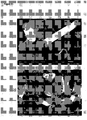
Figur 7 zeigt elektronenmikroskopische Aufnahmen eines derartigen Materials im Vergleich: In der oberen Abbildung sieht man einen erfindungsgemäß eingesetzten Werkstoff, der 28% Glasfasern enthält, ohne dass ein Koppler verwendet wurde. In der unteren Abbildung ist ein entsprechendes Material enthaltend 28% Glasfasern zu sehen, bei dem dem erfindungsgemäß eingesetzten Kunststoffmaterial 1% des Kopplers zugemischt wurde. Deutlich zu erkennen ist die wesentlich bessere Haftung des Kunststoffmaterials an den Glasfasern.Figur 6 zeigt einen ähnlichen Vergleich, bei dem dem Kunststoffmaterial 1% Koppler (unteres Bild), 2% Koppler (mittleres Bild) bzw. kein Koppler (oberes Bild) zugemischt wurde. Auch auf diesen Bildern ist zu erkennen, dass durch die Zugabe des Kopplers die Glasfasern deutlich besser vom Kunststoff umschlossen werden, was zu einer besseren mechanischen Festigkeit führt. - Zur Herstellung des erfindungsgemäß eingesetzten Werkstoffes wird das Kunststoffmaterial zunächst zerkleinert, vorzugsweise mit den Glasfasern vermischt und pelletiert oder agglomeriert. Die Pellets bzw. Agglomerate oder auch die nicht agglomerierten oder pelletierten Vormischungen oder unvermischten Einzelkomponenten werden dann ggf. über eine oder mehrere Dosiereinrichtungen in üblicher Weise, beispielsweise bei Temperaturen zwischen 170° und 230° C extrudiert und regranuliert. Das auf diese Weise hergestellte Regranulat kann dann zur Herstellung der erfindungsgemäßen Formkörper verwendet werden, beispielsweise durch Spritzguss oder Extrusion. Alternativ kann die Verarbeitung direkt (d.h. ohne Regranulierung) zu einem Vollprofil über ein z.B. ölgekühltes Profilwerkzeug mit anschließender Wasserkühlung und Kalibriereinheit verarbeitet werden.
- Zur Erreichung einer integralen Schäumung des Profilkernes können chemische oder physikalische Treibmittel in flüssiger oder fester Form, in die Spritzguß- oder Extrusionswerkstoffe eingeführt werden, z.B. Natriumbicarbonat mit Citronensäure oder thermolabile Carbamate.
- Vorzugsweise werden hierzu endotherme Schäummittel verwendet. Eine weitere Möglichkeit, zu einer Schäumung zu gelangen, ist die Verwendung von Mikrosphären, die beispielsweise mit Gasen oder verdampfbaren Flüssigkeiten gefüllt sind. Zur Füllung eignen sich besonders Alkane wie Butan, Pentan oder Hexan, aber auch deren halogenierte Derivate, wie beispielsweise Dichlormethan oder Perfluorpentan.
- Alternativ kann die Schäumung auch durch Einstellung entsprechender Verfahrensparameter (Temperatur der Extrusion, Abkühlungsrate des Vollprofils) erreicht werden, wenn das Kunststoffmaterial Stoffe enthält, die unter den Verfahrensbedingungen gasförmig werden (z.B. Wasser, Kohlenwasserstoffe, etc.). Vorzugsweise handelt es sich dabei um geschlossene Poren.
- Bei aus dem erfindungsgemäß eingesetzten Material hergestellten Eisenbahnschwellen sind die Poren inhomogen verteilt, nämlich insbesondere im Kern des Formkörpers konzentriert.
- Dies sei an Hand der
Figuren 1-3 illustriert: -
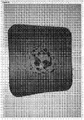
Figuren 1 und2 zeigen den Querschnitt eines rechtwinkligen, extrudierten Formkörpers mit den Kantenlängen I1 und I2. Durch Teilung der Kantenlängen erhält man einen Formkörperkern K mit den Kantenlängen ½ I1 und ½ I2, welcher 25% der Gesamtfläche ausmacht. Weiterhin erhält man einen erweiterten Formkörperkern K2 mit den Kantenlängen ¾ I1 und ¾ I2, welcher ca. 56% (genauer 9/16) der Gesamtfläche ausmacht. Ferner erhält man eine Randzone Rz, deren Fläche ca. 44% (genauer 7/16) der Gesamtfläche ausmacht (I1 x I2 - ¾ I1 x ¾ I2 = 7/16 x I1 x I2). Für die bevorzugte Ausführungsform geschäumter Formkörper aus dem erfindungsgemäß eingesetzten Material ist nun wesentlich, dass im Formkörperkern K mehr als 50% des Gesamtporenvolumens vorhanden sind, wobei die Poren jeweils 1 - 15 mm Durchmesser, vorzugsweise 3 - 7 mm Durchmesser aufweisen sollen. Im erweiterten Formkörperkern K2 sollen mehr als 85 % des Gesamtporenvolumens vorhanden sein. In der Randzone Rz sollen weniger als 15%, bevorzugt weniger als 5%, ganz besonders bevorzugt weniger als 1% des Gesamtporenvolumens enthalten sein. -
Figur 3 zeigt einen Schnitt eines solchen Materials mit den enthaltenen Poren. Die in denFiguren 1 und2 angedeuteten geometrischen Verhältnisse lassen sich in analoger Weise auf andere Formkörpergestaltungen und -profile übertragen. - Bei der Herstellung erfindungsgemäßer Eisenbahnschwellen als Formkörper ist in jedem Fall zu beachten, dass die durch die Verfahrensschritte auftretenden Scherkräfte (beispielsweise bei der Extrusion) die Glasfasern nicht zu stark schädigen. Wie eingangs bereits beschrieben ist es für die mechanischen Eigenschaften des erfindungsgemäß eingesetzten Werkstoffs von entscheidender Bedeutung, dass die Glasfasern im erfindungsgemäß eingesetzten Material Längen von 2 - 20 mm aufweisen, so dass mindestens 80% der Glasfasern in diesem Längenbereich liegen.
- Bei der Herstellung der erfindungsgemäß eingesetzten Materialien hat sich gezeigt, dass diese auch die hohen Anforderungen an mechanischen Eigenschaften, wie sie beim Bau von Eisenbahnschwellen gefordert werden, erfüllen. So zeigen die erfindungsgemäß eingesetzten Werkstoffe enthaltend ca. 20% Glasfasern in ca. 80% HDPE bei Biegeversuchen ein E-Modul von mindestens 4.500 MPa. In Abhängigkeit von den genauen Prozessparametern wurden auch deutlich höhere Werte gemessen, bis hin zu 5.000 MPa und darüber hinaus. Dies sind Werte, der überraschend deutlich über dem E-Modul des Standes der Technik (
DE19503632C1 ) von ca. 1.500 MPa liegt. Dabei weist das erfindungsgemäß eingesetzte Material eine Zugfestigkeit von ca. 24 MPa auf. Darüber hinaus sind auch Biegefestigkeit, wie auch die Schlagzähigkeit außergewöhnlich hoch. - Erfindungsgemäß eingesetzte Werkstoffe, die unter Verwendung von den oben genannten Silanschlichten und einem Koppler hergestellt wurden, erreichen darüber hinaus Werte von bis zu 800.000 MPa für das Biege-E-Modul bzw. von ca. 7.000 MPa der Biegefestigkeit. Derartige Werte wurden mit den aus dem Stand der Technik bekannten Materialien nicht erreicht, es war auch nicht naheliegend, dass die erfindungsgemäße Modifizierung bekannter Werkstoffe zu derartig hohen Werten führt.
- Aufgrund dieser hervorragenden Werte erfüllen die erfindungsgemäß eingesetzten Werkstoffe überraschenderweise die Anforderungen der DIN EN 1346-4 und sind somit als Bahnschwellen geeignet. Aus den erfindungsgemäß eingesetzten Materialien gefertigte Bahnschwellen halten den für diesen Verwendungszweck üblichen Lasten von 85 KN Stand, überstehen dabei mindestens 2 Millionen Lastwechsel und lassen sich mit den üblichen Verankerungssystemen, wie beispielsweise Bahnschwellenschrauben, befestigen. Auch die mehrfache Wiederbefestigung der Schwellen ist möglich. Derartige Bahnschwellen überstehen auch die direkte Sonneneinstrahlung sowie Hitzeinwirkung in hervorragender Weise. Durch Dauerbelastungstests (z.B. bei 64°C) kann diese besondere Eigenschaft nachgewiesen werden.
- Vorteile der aus den erfindungsgemäß eingesetzten Materialien gefertigten Bahnschwellen gegenüber Holzschwellen bestehen insbesondere darin, dass diese länger haltbar sind (< 50 Jahre im Vergleich zu 15 - 30 Jahren bei Holzschwellen) und keinerlei Emissionen von Holzschutzmitteln aufweisen. Auch im Vergleich mit Betonschwellen, die durch Abplatzungen verschleißen, weisen die aus den erfindungsgemäß eingesetzten Werkstoffen hergestellten Kunststoffschwellen eine deutlich längere Haltbarkeit auf. Ein besonderer Gesichtspunkt der vorliegenden Erfindung ist daher eine Bahnschwelle bestehend aus dem erfindungsgemäß eingesetzten Material.
- Ein besonderer Vorteil der erfindungsgemäßen Bahnschwellen ist die durch die integrale Schäumung erzeugten geschlossenen Poren von 1 - 15 mm Durchmesser, vorzugsweise 3 - 7 mm Durchmesser überraschend hervorgerufene Dämpfung von Körperschallschwingungen im für das menschliche Ohr hörbaren und nicht hörbaren Bereich. Dieser Effekt wird durch den Zusatz von Kautschuk-Mehl zur Extrusionsmischung weiter verbessert. Der Zusatz erfolgt in diesem Fall in einem Mengenbereich von 1 - 8 Masse-%, vorzugsweise 2 - 3 Masse-% der Polyolefin-Glasfaser-Mischung.
- Körperschall führt bei Schwellen aus Beton zu einem Zerreiben des Schotters. Letzterer führt zu einem erhöhten Wartungsaufwand von Schienenverbindungen, da sich derart geschädigte Schotterbetten nicht mehr durch Stopfen verfestigen und aufarbeiten lassen. Die Körperschalldämpfungseigenschaften des erfindungsgemäß eingesetzten Materials führen somit zu einer deutlichen Verringerung bis zur Einstellung des genannten Schotterabriebs und somit zu einer Verlängerung der Liegezeiten der Schienen-Schwellen-Gleisbett-Konstruktion. Außerdem führt der Körperschall durch Übertragung auf an das Gleisbett angrenzende Bauten zu Bauwerksschäden durch Rißbildungen und Abplatzungen im Bauwerk und zur Lärmbelästigung von Anwohnern, was durch die erfindungsgemäße Kunststoffschwelle entscheidend verringert wird.
- Ein weiterer Vorteil der erfindungsgemäßen Formkörper, insbesondere Bahnschwellen, ist die durch die integrale Schäumung erzeugte, verminderte Materialdichte. Es wird daher weniger Material verbraucht, was zu entsprechenden Kosteneinsparungen führt. Die Formkörper, also Eisenbahnschwellen, sind daher bei gleichem Volumen leichter und daher einfacher im Transport und im Einbau. Die Dichte von erfindungsgemäßen Formkörpern kann auf diese Weise beispielsweise von ca. 1,1 -1,4 g/cm3 (ungeschäumtes Material) auf 0,75 - 1,25 g/cm3, vorzugsweise ca. 0,95 g/cm3 (geschäumtes Material) gesenkt werden.
- Bei der Herstellung von Bahnschwellen aus dem erfindungsgemäß eingesetzten Material können gleichzeitig ein oder mehrere Kanäle bei der Extrusion mittels entsprechend angepasster Werkzeuge eingeformt werden. So kann beispielsweise ein zentraler Kanal gebildet werden, der seinerseits entweder rund oder oval ist oder auch eine andere geometrische Form aufweisen kann. Mittels dieses Kanals kann das Material bei der Herstellung gekühlt werden. Das Extrusionswerkzeug ist dann so ausgeformt, dass an dieser Stelle ein Kühlkanal verläuft.
- Im Fall des erfindungsgemäß eingesetzten Materials mit integraler Schäumung führt die Einführung eines derartigen Kanals unter entsprechender Kühlung zu einer entsprechend anderen Porenverteilung, so wie sie in der
Figur 4 schematisch dargestellt ist. Der zentrale Kanal ist in derFigur 4 mit D gekennzeichnet. Der Formkörper weist in seinem äußeren Bereich (A) sowie in einem um den Kanal D konzentrischen Bereich (C) wenig bis gar keine Poren auf. In dem mittleren Teil B sind die Mehrzahl der Poren enthalten. Bei dieser Art der Porenverteilung ist die mechanische Stabilität des gesamten Formkörpers sichergestellt, während gleichzeitig die bereits oben dargestellten Vorteile der Schäumung erhalten bleiben. Ein wichtiger Vorteil des in dieser Weise geformten Kanals ist die Möglichkeit, Kabel durch die Schwelle hindurchzuführen. Diese Form der Schwelle löst ein häufig auftretendes Problem von Bahnbetreibern, nämlich elektrische Kabel (z.B. zur Steuerung von Signalen und Weichen) von einer Seite einer Schiene auf die andere Seite führen zu müssen. Mit den üblichen Methoden muss ein Tunnel unter der Schiene gegraben werden, während der erfindungsgemäße Formkörper eine einfache Durchführung gestattet. Es versteht sich von selbst, dass diese Durchführung auch zu jedem beliebigen Zeitpunkt vorgenommen werden kann, ohne dass der Schienenverkehr unterbrochen werden muss. - Eine weitere Ausführungsform der Erfindung besteht darin, einen Formkörper aus zwei oder mehr Schichten zu bilden. Hierzu wird, vorzugsweise im Wege der gleichzeitigen Extrusion, dem erfindungsgemäßen Formkörper auf einer Seite eine oder mehrere Schichten an-extrudiert, wie es beispielhaft in der
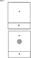
Figur 5 zu sehen ist. Eine Seite des erfindungsgemäßen Formkörpers A enthält eine zusätzliche Schicht eines Materials anderer Zusammensetzung. Bei diesem anderen Material handelt es sich beispielsweise um ein weicheres Material, welches z.B. einen Gummianteil enthält. Bei einer derartig ausgestalteten Bahnschwelle zeigt sich, dass sich der Schotter deutlich besser in das Material eindrückt, was zu einer erwünschten Veränderung des Querverschiebewiderstands beiträgt. Gleichzeitig erfolgt eine weitere Schalldämpfung und eine weitere Verringerung des Schotterabriebs. Im Rahmen einer derartigen Ausführungsform kann die ergänzende Schicht B beispielsweise 5% - 30% Gummi enthalten. Der hierzu notwendige Gummianteil stammt bevorzugt aus Produktionsabfällen, beispielsweise aus der Produktion von Reifen oder von Gummidichtungen aller Art. Möglich ist selbstverständlich auch, mehrere Schichten mit verschiedenen Gummianteilen anzubringen. Selbstverständlich ist auch in dieser Ausführungsform die Bildung eines Kanals möglich, so wie in derFigur 5 unten schematisch dargestellt. Im Fall eines geschäumten Körpers ist die Porenverteilung analog zur oben bereits dargestelltenFigur 4 .
Claims (8)
- Eisenbahnschwelle, enthaltend einen thermoplastischen Werkstoff, enthaltend mindestens 75% Polyolefine aus Recyclingmaterial und mindestens 10% geschlichtete Glasfaser, wobei es sich bei den Glasfasern um Schnittglasfasern handelt von denen wenigstens 80% eine Länge von 2-20 mm aufweisen, dadurch gekennzeichnet, dass in einer Kernzone (K), entsprechend 25% der Querschnittsfläche der Eisenbahnschwelle, geschlossene Poren von jeweils 1-15 mm Durchmesser enthalten sind, wobei die in der Kernzone (K) enthaltenen Poren mehr als 50% des Gesamtporenvolumens ausmachen.
- Eisenbahnschwelle gemäß Anspruch 1, dadurch gekennzeichnet, dass als Recylingpolyolefin Material aus formstabilen Kunststoffbehältern verwendet wird.
- Eisenbahnschwelle gemäß Anspruch 2, dadurch gekennzeichnet, dass als Kunststoffflaschenmaterial Ölgebinde verwendet werden.
- Eisenbahnschwelle gemäß Anspruch 1, dadurch gekennzeichnet, dass die Glasfasern beschichtet sind mit Acrylat-Butadien-Copolymeren, Latex, oder anderen Kautschuken.
- Eisenbahnschwelle gemäß Anspruch 1, dadurch gekennzeichnet, dass die Glasfasern mit Silanschlichten beschichtet sind und dass den Polyolefinen ein Koppler zugegeben wird.
- Eisenbahnschwelle gemäß Anspruch 5, dadurch gekennzeichnet, dass als Koppler ein Maleinsäureanhydrat-Derivat verwendet wird.
- Eisenbahnschwelle gemäß einem der vorangehenden Ansprüche, gekennzeichnet durch ein Dichte von 0,9 - 1,0 g/cm3.
- Eisenbahnschwelle gemäß einem der vorangehenden Ansprüche, enthaltend einen oder mehrere zentrale Kanäle.
Priority Applications (4)
| Application Number | Priority Date | Filing Date | Title |
|---|---|---|---|
| RS20180736A RS57357B1 (sr) | 2011-11-07 | 2012-11-07 | Termoplastični materijal koji sadrži reciklirani poliolefin i staklena vlakna |
| HRP20181157TT HRP20181157T1 (hr) | 2011-11-07 | 2012-11-07 | Termoplastični materijal koji sadrži reciklirani poliolefin i staklena vlakna |
| SI201231297T SI2776494T1 (en) | 2011-11-07 | 2012-11-07 | Thermoplastic material containing recycled polyolefin and glass fibers |
| PL12798596T PL2776494T3 (pl) | 2011-11-07 | 2012-11-07 | Materiał termoplastyczny zawierający pochodzącą z recyklingu poliolefinę i włókna szklane |
Applications Claiming Priority (2)
| Application Number | Priority Date | Filing Date | Title |
|---|---|---|---|
| DE201110117760 DE102011117760A1 (de) | 2011-11-07 | 2011-11-07 | Thermoplastischer Werkstoff enthaltend Recycling-Polyolefin und Glasfasern |
| PCT/DE2012/001062 WO2013067990A1 (de) | 2011-11-07 | 2012-11-07 | Thermoplastischer werkstoff enthaltend recycling-polyolefin und glasfasern |
Publications (2)
| Publication Number | Publication Date |
|---|---|
| EP2776494A1 EP2776494A1 (de) | 2014-09-17 |
| EP2776494B1 true EP2776494B1 (de) | 2018-05-02 |
Family
ID=47325746
Family Applications (1)
| Application Number | Title | Priority Date | Filing Date |
|---|---|---|---|
| EP12798596.8A Active EP2776494B1 (de) | 2011-11-07 | 2012-11-07 | Thermoplastischer werkstoff enthaltend recycling-polyolefin und glasfasern |
Country Status (14)
| Country | Link |
|---|---|
| EP (1) | EP2776494B1 (de) |
| DE (1) | DE102011117760A1 (de) |
| DK (1) | DK2776494T3 (de) |
| ES (1) | ES2671931T3 (de) |
| HR (1) | HRP20181157T1 (de) |
| HU (1) | HUE038921T2 (de) |
| LT (1) | LT2776494T (de) |
| NO (1) | NO2852554T3 (de) |
| PL (1) | PL2776494T3 (de) |
| PT (1) | PT2776494T (de) |
| RS (1) | RS57357B1 (de) |
| SI (1) | SI2776494T1 (de) |
| TR (1) | TR201807925T4 (de) |
| WO (1) | WO2013067990A1 (de) |
Cited By (1)
| Publication number | Priority date | Publication date | Assignee | Title |
|---|---|---|---|---|
| WO2021239694A1 (en) | 2020-05-27 | 2021-12-02 | Borealis Ag | Reinforced polyolefin composition comprising recycled plastic material |
Families Citing this family (9)
| Publication number | Priority date | Publication date | Assignee | Title |
|---|---|---|---|---|
| ES2625736T3 (es) | 2014-09-10 | 2017-07-20 | Starlinger & Co. Gesellschaft M.B.H. | Dispositivo y procedimiento para la producción de un material compuesto polimérico relleno |
| DE102016111922B4 (de) | 2016-06-29 | 2022-05-05 | Pioonier GmbH | Verfahren zur Herstellung eines Formkörpers und ein Werkzeug hierfür |
| DE102018112782A1 (de) | 2018-05-29 | 2019-12-05 | KRAIBURG STRAIL GmbH & Co. KG | Eisenbahnschwelle |
| DE102018010316A1 (de) | 2018-05-29 | 2019-12-05 | KRAIBURG STRAIL GmbH & Co. KG | Eisenbahnschwelle |
| JP2023529179A (ja) * | 2020-06-03 | 2023-07-07 | ブラスケム・エス・エー | 鉄道枕木 |
| CN111909431A (zh) * | 2020-08-05 | 2020-11-10 | 大连广盛元实业有限公司 | 一种新型轨道减震复合材料、其制备方法及应用 |
| CN112223774A (zh) * | 2020-09-11 | 2021-01-15 | 山东高速交通装备有限公司 | 热塑性塑料玻纤挤出复合轨枕制备方法及系统 |
| DE102021106195A1 (de) | 2021-03-15 | 2022-09-15 | Reimund Dann | Eisenbahnschwelle aus Kunststoff |
| DE102022107060A1 (de) | 2022-03-25 | 2023-09-28 | Johannes Wissing | Verfahren und Anordnung zum Extrudieren von Recyclingmaterial |
Family Cites Families (11)
| Publication number | Priority date | Publication date | Assignee | Title |
|---|---|---|---|---|
| FR2409282A1 (fr) * | 1977-11-18 | 1979-06-15 | Rhone Poulenc Ind | Compositions a base de polypropylene et de fibres de verre |
| US5030662A (en) * | 1988-08-11 | 1991-07-09 | Polymerix, Inc. | Construction material obtained from recycled polyolefins containing other polymers |
| DE4322108C2 (de) * | 1992-07-03 | 2001-08-09 | Toyoda Gosei Kk | Verstärkte Polypropylenharzmischung und daraus hergestellte Radkappe |
| DE19503632C1 (de) | 1995-01-26 | 1996-04-25 | Brauer Hans Joachim | Verfahren zur Herstellung von thermoplastischen Werkstoffen durch Einarbeiten von Glasfaservlies unter Verwendung von recycelten Materialien |
| DE19610362A1 (de) | 1996-03-15 | 1997-09-18 | Basf Ag | Funktionalisierte Polymere, Verfahren zu ihrer Herstellung, diese enthaltende Formmassen und Formkörper |
| US5886078A (en) * | 1996-08-13 | 1999-03-23 | Tietek, Inc. | Polymeric compositions and methods for making construction materials from them |
| US5789477A (en) * | 1996-08-30 | 1998-08-04 | Rutgers, The State University | Composite building materials from recyclable waste |
| DE19819750C2 (de) | 1998-05-02 | 2001-12-13 | Fraunhofer Ges Forschung | Verbundwerkstoff und Verfahren zu seiner Herstellung |
| DE10150678A1 (de) | 2001-10-17 | 2003-05-08 | Fagerdala Deutschland Gmbh | Leichtes Kunststoff-Verbundmaterial |
| EP1460166B1 (de) * | 2001-12-27 | 2015-10-21 | Fiber Glass Japan Kabushiki Kaisha | Bindemittel für glasfaser, glasfaser als verstärkungsmittel für olefinharz sowie verfahren zur herstellung einer olefinharz zusammensetzung für faserverstärkte formkörper |
| WO2008148898A1 (es) * | 2007-06-07 | 2008-12-11 | Ulma C Y E, S. Coop. | Composición, procedimiento e instalación para obtener en continuo una plancha espumada de naturaleza polimérica y plancha así obtenida |
-
2011
- 2011-11-07 DE DE201110117760 patent/DE102011117760A1/de not_active Ceased
-
2012
- 2012-11-07 SI SI201231297T patent/SI2776494T1/en unknown
- 2012-11-07 ES ES12798596.8T patent/ES2671931T3/es active Active
- 2012-11-07 PL PL12798596T patent/PL2776494T3/pl unknown
- 2012-11-07 RS RS20180736A patent/RS57357B1/sr unknown
- 2012-11-07 WO PCT/DE2012/001062 patent/WO2013067990A1/de not_active Ceased
- 2012-11-07 LT LTEP12798596.8T patent/LT2776494T/lt unknown
- 2012-11-07 HR HRP20181157TT patent/HRP20181157T1/hr unknown
- 2012-11-07 EP EP12798596.8A patent/EP2776494B1/de active Active
- 2012-11-07 DK DK12798596.8T patent/DK2776494T3/en active
- 2012-11-07 HU HUE12798596A patent/HUE038921T2/hu unknown
- 2012-11-07 TR TR2018/07925T patent/TR201807925T4/tr unknown
- 2012-11-07 PT PT127985968T patent/PT2776494T/pt unknown
-
2013
- 2013-03-15 NO NO13712721A patent/NO2852554T3/no unknown
Non-Patent Citations (1)
| Title |
|---|
| None * |
Cited By (1)
| Publication number | Priority date | Publication date | Assignee | Title |
|---|---|---|---|---|
| WO2021239694A1 (en) | 2020-05-27 | 2021-12-02 | Borealis Ag | Reinforced polyolefin composition comprising recycled plastic material |
Also Published As
| Publication number | Publication date |
|---|---|
| DK2776494T3 (en) | 2018-08-06 |
| LT2776494T (lt) | 2018-05-25 |
| WO2013067990A1 (de) | 2013-05-16 |
| PT2776494T (pt) | 2018-08-08 |
| ES2671931T3 (es) | 2018-06-11 |
| RS57357B1 (sr) | 2018-08-31 |
| TR201807925T4 (tr) | 2018-06-21 |
| PL2776494T3 (pl) | 2018-10-31 |
| HUE038921T2 (hu) | 2018-12-28 |
| NO2852554T3 (de) | 2018-05-19 |
| EP2776494A1 (de) | 2014-09-17 |
| DE102011117760A1 (de) | 2013-05-08 |
| HRP20181157T1 (hr) | 2018-09-21 |
| SI2776494T1 (en) | 2018-06-29 |
Similar Documents
| Publication | Publication Date | Title |
|---|---|---|
| EP2776494B1 (de) | Thermoplastischer werkstoff enthaltend recycling-polyolefin und glasfasern | |
| DE69718653T2 (de) | Polymerzusammensetzungen und verfahren zur herstellung von baumaterialien daraus | |
| DE4408855A1 (de) | Faserverstärkter, kompakt bis zelliger Kunststoff und Verwendung desselben | |
| WO2021032511A1 (de) | Selektives sintern von polymerbasierten verbundwerkstoffen | |
| WO2005040254A1 (de) | Extrusionsverfahren zur herstellung von zähmodifizierten und schichtsilikatverstärkten thermoplastischen systemen | |
| AT405658B (de) | Oberbau mit betonschwellen | |
| DE102012216727A1 (de) | Funktionsoptimiertes Faserverbundbauteil und Verfahren zu dessen Herstellung | |
| WO2001029319A1 (de) | Röhrenmatte | |
| DE102007042287B4 (de) | Verfahren zur Herstellung eines Faserverbundbauteils | |
| DE102008060102A1 (de) | Lärmschutzeinrichtung und Zuschlagstoff für die Ausbildung einer Absorberschicht einer Lärmschutzeinrichtung | |
| EP2871052B1 (de) | Kfz-innenverkleidungsteil | |
| DE102007007421A1 (de) | Stoffgemisch, insbesondere verwendbar als Zuschlagmittel für Beton | |
| DE102013204690A1 (de) | Verbundwerkstoff für einen thermischen Energiespeicher und Verfahren zum Herstellen eines Verbundwerkstoffs für einen thermischen Energiespeicher | |
| AT524136B1 (de) | Kautschukzusammensetzung für eine Schienenzwischenlage | |
| DE102009039185A1 (de) | Mehrschichtiges Material, etwa zur Herstellung von Fahrzeugverkleidungsteilen, insbesondere zur Herstellung von Radhaus- oder Motorraumverkleidungsteilen | |
| EP3263767B1 (de) | Eisenbahnschwelle sowie verfahren zur herstellung einer solchen | |
| DE60121318T2 (de) | Verfahren zur herstellung eines körnigen kautschukmaterials und dessen verwendung in bitumen | |
| EP4560088A2 (de) | Bahnförmiges produkt sowie herstellung eines solchen | |
| DE202014010826U1 (de) | Schwerentflammbares und selbsterlöschendes Faserbauteil | |
| DE202008018615U1 (de) | Geozelle für Lasttraganwendungen | |
| DE102012111097A1 (de) | Komposit, Bauteil hieraus sowie Verfahren zur Herstellung hierfür | |
| EP2374611A1 (de) | Betonschaltafel | |
| DE202013006307U1 (de) | Vliesstoff-Formteil und Vliesstoff-Halbzeug | |
| EP2915788B1 (de) | Leichter Verbundwerkstoff | |
| DE20203808U1 (de) | Dämmende Außenverkleidung für Fahrzeuge mit Faservliesen |
Legal Events
| Date | Code | Title | Description |
|---|---|---|---|
| PUAI | Public reference made under article 153(3) epc to a published international application that has entered the european phase |
Free format text: ORIGINAL CODE: 0009012 |
|
| 17P | Request for examination filed |
Effective date: 20140327 |
|
| AK | Designated contracting states |
Kind code of ref document: A1 Designated state(s): AL AT BE BG CH CY CZ DE DK EE ES FI FR GB GR HR HU IE IS IT LI LT LU LV MC MK MT NL NO PL PT RO RS SE SI SK SM TR |
|
| DAX | Request for extension of the european patent (deleted) | ||
| RAP1 | Party data changed (applicant data changed or rights of an application transferred) |
Owner name: KRAIBURG STRAIL GMBH & CO. KG |
|
| RIN1 | Information on inventor provided before grant (corrected) |
Inventor name: BRAUER, HANS-JOACHIM |
|
| STAA | Information on the status of an ep patent application or granted ep patent |
Free format text: STATUS: EXAMINATION IS IN PROGRESS |
|
| 17Q | First examination report despatched |
Effective date: 20170531 |
|
| GRAP | Despatch of communication of intention to grant a patent |
Free format text: ORIGINAL CODE: EPIDOSNIGR1 |
|
| STAA | Information on the status of an ep patent application or granted ep patent |
Free format text: STATUS: GRANT OF PATENT IS INTENDED |
|
| INTG | Intention to grant announced |
Effective date: 20171205 |
|
| GRAS | Grant fee paid |
Free format text: ORIGINAL CODE: EPIDOSNIGR3 |
|
| GRAA | (expected) grant |
Free format text: ORIGINAL CODE: 0009210 |
|
| STAA | Information on the status of an ep patent application or granted ep patent |
Free format text: STATUS: THE PATENT HAS BEEN GRANTED |
|
| AK | Designated contracting states |
Kind code of ref document: B1 Designated state(s): AL AT BE BG CH CY CZ DE DK EE ES FI FR GB GR HR HU IE IS IT LI LT LU LV MC MK MT NL NO PL PT RO RS SE SI SK SM TR |
|
| REG | Reference to a national code |
Ref country code: GB Ref legal event code: FG4D Free format text: NOT ENGLISH |
|
| REG | Reference to a national code |
Ref country code: CH Ref legal event code: EP Ref country code: CH Ref legal event code: NV Representative=s name: E. BLUM AND CO. AG PATENT- UND MARKENANWAELTE , CH Ref country code: AT Ref legal event code: REF Ref document number: 995187 Country of ref document: AT Kind code of ref document: T Effective date: 20180515 |
|
| REG | Reference to a national code |
Ref country code: RO Ref legal event code: EPE |
|
| REG | Reference to a national code |
Ref country code: DE Ref legal event code: R096 Ref document number: 502012012645 Country of ref document: DE Ref country code: IE Ref legal event code: FG4D Free format text: LANGUAGE OF EP DOCUMENT: GERMAN |
|
| REG | Reference to a national code |
Ref country code: ES Ref legal event code: FG2A Ref document number: 2671931 Country of ref document: ES Kind code of ref document: T3 Effective date: 20180611 |
|
| REG | Reference to a national code |
Ref country code: SE Ref legal event code: TRGR |
|
| REG | Reference to a national code |
Ref country code: DE Ref legal event code: R082 Ref document number: 502012012645 Country of ref document: DE Representative=s name: RUTTENSPERGER LACHNIT TROSSIN GOMOLL PATENT- U, DE Ref country code: DE Ref legal event code: R082 Ref document number: 502012012645 Country of ref document: DE Representative=s name: RUTTENSPERGER LACHNIT TROSSIN GOMOLL, PATENT- , DE |
|
| REG | Reference to a national code |
Ref country code: NL Ref legal event code: FP |
|
| REG | Reference to a national code |
Ref country code: EE Ref legal event code: FG4A Ref document number: E015500 Country of ref document: EE Effective date: 20180515 |
|
| REG | Reference to a national code |
Ref country code: HR Ref legal event code: TUEP Ref document number: P20181157 Country of ref document: HR |
|
| REG | Reference to a national code |
Ref country code: DK Ref legal event code: T3 Effective date: 20180730 |
|
| REG | Reference to a national code |
Ref country code: PT Ref legal event code: SC4A Ref document number: 2776494 Country of ref document: PT Date of ref document: 20180808 Kind code of ref document: T Free format text: AVAILABILITY OF NATIONAL TRANSLATION Effective date: 20180802 |
|
| REG | Reference to a national code |
Ref country code: NO Ref legal event code: T2 Effective date: 20180502 |
|
| REG | Reference to a national code |
Ref country code: HR Ref legal event code: T1PR Ref document number: P20181157 Country of ref document: HR |
|
| REG | Reference to a national code |
Ref country code: GR Ref legal event code: EP Ref document number: 20180401403 Country of ref document: GR Effective date: 20181012 |
|
| REG | Reference to a national code |
Ref country code: HU Ref legal event code: AG4A Ref document number: E038921 Country of ref document: HU |
|
| REG | Reference to a national code |
Ref country code: DE Ref legal event code: R097 Ref document number: 502012012645 Country of ref document: DE |
|
| PG25 | Lapsed in a contracting state [announced via postgrant information from national office to epo] |
Ref country code: SM Free format text: LAPSE BECAUSE OF FAILURE TO SUBMIT A TRANSLATION OF THE DESCRIPTION OR TO PAY THE FEE WITHIN THE PRESCRIBED TIME-LIMIT Effective date: 20180502 |
|
| PLBE | No opposition filed within time limit |
Free format text: ORIGINAL CODE: 0009261 |
|
| STAA | Information on the status of an ep patent application or granted ep patent |
Free format text: STATUS: NO OPPOSITION FILED WITHIN TIME LIMIT |
|
| 26N | No opposition filed |
Effective date: 20190205 |
|
| PG25 | Lapsed in a contracting state [announced via postgrant information from national office to epo] |
Ref country code: MC Free format text: LAPSE BECAUSE OF FAILURE TO SUBMIT A TRANSLATION OF THE DESCRIPTION OR TO PAY THE FEE WITHIN THE PRESCRIBED TIME-LIMIT Effective date: 20180502 |
|
| REG | Reference to a national code |
Ref country code: HR Ref legal event code: ODRP Ref document number: P20181157 Country of ref document: HR Payment date: 20191022 Year of fee payment: 8 |
|
| PG25 | Lapsed in a contracting state [announced via postgrant information from national office to epo] |
Ref country code: AL Free format text: LAPSE BECAUSE OF FAILURE TO SUBMIT A TRANSLATION OF THE DESCRIPTION OR TO PAY THE FEE WITHIN THE PRESCRIBED TIME-LIMIT Effective date: 20180502 |
|
| PG25 | Lapsed in a contracting state [announced via postgrant information from national office to epo] |
Ref country code: MT Free format text: LAPSE BECAUSE OF FAILURE TO SUBMIT A TRANSLATION OF THE DESCRIPTION OR TO PAY THE FEE WITHIN THE PRESCRIBED TIME-LIMIT Effective date: 20180502 |
|
| PG25 | Lapsed in a contracting state [announced via postgrant information from national office to epo] |
Ref country code: CY Free format text: LAPSE BECAUSE OF FAILURE TO SUBMIT A TRANSLATION OF THE DESCRIPTION OR TO PAY THE FEE WITHIN THE PRESCRIBED TIME-LIMIT Effective date: 20180502 |
|
| PG25 | Lapsed in a contracting state [announced via postgrant information from national office to epo] |
Ref country code: IS Free format text: LAPSE BECAUSE OF FAILURE TO SUBMIT A TRANSLATION OF THE DESCRIPTION OR TO PAY THE FEE WITHIN THE PRESCRIBED TIME-LIMIT Effective date: 20180902 |
|
| REG | Reference to a national code |
Ref country code: HR Ref legal event code: ODRP Ref document number: P20181157 Country of ref document: HR Payment date: 20201102 Year of fee payment: 9 |
|
| REG | Reference to a national code |
Ref country code: HR Ref legal event code: ODRP Ref document number: P20181157 Country of ref document: HR Payment date: 20211105 Year of fee payment: 10 |
|
| REG | Reference to a national code |
Ref country code: HR Ref legal event code: ODRP Ref document number: P20181157 Country of ref document: HR Payment date: 20221028 Year of fee payment: 11 |
|
| REG | Reference to a national code |
Ref country code: HR Ref legal event code: ODRP Ref document number: P20181157 Country of ref document: HR Payment date: 20231026 Year of fee payment: 12 |
|
| REG | Reference to a national code |
Ref country code: HR Ref legal event code: ODRP Ref document number: P20181157 Country of ref document: HR Payment date: 20241024 Year of fee payment: 13 |
|
| REG | Reference to a national code |
Ref country code: HR Ref legal event code: ODRP Ref document number: P20181157 Country of ref document: HR Payment date: 20251030 Year of fee payment: 14 |
|
| REG | Reference to a national code |
Ref country code: CH Ref legal event code: U11 Free format text: ST27 STATUS EVENT CODE: U-0-0-U10-U11 (AS PROVIDED BY THE NATIONAL OFFICE) Effective date: 20251201 |
|
| PGFP | Annual fee paid to national office [announced via postgrant information from national office to epo] |
Ref country code: PT Payment date: 20251030 Year of fee payment: 14 |
|
| PGFP | Annual fee paid to national office [announced via postgrant information from national office to epo] |
Ref country code: HU Payment date: 20251121 Year of fee payment: 14 |
|
| PGFP | Annual fee paid to national office [announced via postgrant information from national office to epo] |
Ref country code: NL Payment date: 20251119 Year of fee payment: 14 Ref country code: LU Payment date: 20251119 Year of fee payment: 14 |
|
| PGFP | Annual fee paid to national office [announced via postgrant information from national office to epo] |
Ref country code: DE Payment date: 20251119 Year of fee payment: 14 |
|
| PGFP | Annual fee paid to national office [announced via postgrant information from national office to epo] |
Ref country code: LT Payment date: 20251027 Year of fee payment: 14 Ref country code: GB Payment date: 20251121 Year of fee payment: 14 |
|
| PGFP | Annual fee paid to national office [announced via postgrant information from national office to epo] |
Ref country code: NO Payment date: 20251125 Year of fee payment: 14 |
|
| PGFP | Annual fee paid to national office [announced via postgrant information from national office to epo] |
Ref country code: MK Payment date: 20251022 Year of fee payment: 14 Ref country code: AT Payment date: 20251120 Year of fee payment: 14 |
|
| PGFP | Annual fee paid to national office [announced via postgrant information from national office to epo] |
Ref country code: IT Payment date: 20251125 Year of fee payment: 14 Ref country code: FI Payment date: 20251125 Year of fee payment: 14 Ref country code: DK Payment date: 20251125 Year of fee payment: 14 |
|
| PGFP | Annual fee paid to national office [announced via postgrant information from national office to epo] |
Ref country code: HR Payment date: 20251030 Year of fee payment: 14 Ref country code: FR Payment date: 20251125 Year of fee payment: 14 |
|
| PGFP | Annual fee paid to national office [announced via postgrant information from national office to epo] |
Ref country code: TR Payment date: 20251103 Year of fee payment: 14 Ref country code: BE Payment date: 20251119 Year of fee payment: 14 Ref country code: GR Payment date: 20251120 Year of fee payment: 14 |
|
| PGFP | Annual fee paid to national office [announced via postgrant information from national office to epo] |
Ref country code: SE Payment date: 20251119 Year of fee payment: 14 Ref country code: CH Payment date: 20251201 Year of fee payment: 14 |
|
| PGFP | Annual fee paid to national office [announced via postgrant information from national office to epo] |
Ref country code: IE Payment date: 20251121 Year of fee payment: 14 Ref country code: CZ Payment date: 20251030 Year of fee payment: 14 |
|
| PGFP | Annual fee paid to national office [announced via postgrant information from national office to epo] |
Ref country code: LV Payment date: 20251116 Year of fee payment: 14 |
|
| PGFP | Annual fee paid to national office [announced via postgrant information from national office to epo] |
Ref country code: PL Payment date: 20251031 Year of fee payment: 14 Ref country code: BG Payment date: 20251120 Year of fee payment: 14 |
|
| PGFP | Annual fee paid to national office [announced via postgrant information from national office to epo] |
Ref country code: EE Payment date: 20251120 Year of fee payment: 14 |
|
| PGFP | Annual fee paid to national office [announced via postgrant information from national office to epo] |
Ref country code: SK Payment date: 20251104 Year of fee payment: 14 Ref country code: RO Payment date: 20251103 Year of fee payment: 14 |
|
| PGFP | Annual fee paid to national office [announced via postgrant information from national office to epo] |
Ref country code: RS Payment date: 20251031 Year of fee payment: 14 |
|
| PGFP | Annual fee paid to national office [announced via postgrant information from national office to epo] |
Ref country code: SI Payment date: 20251030 Year of fee payment: 14 Ref country code: ES Payment date: 20251229 Year of fee payment: 14 |