EP2775792B1 - Cooking device - Google Patents
Cooking device Download PDFInfo
- Publication number
- EP2775792B1 EP2775792B1 EP14401016.2A EP14401016A EP2775792B1 EP 2775792 B1 EP2775792 B1 EP 2775792B1 EP 14401016 A EP14401016 A EP 14401016A EP 2775792 B1 EP2775792 B1 EP 2775792B1
- Authority
- EP
- European Patent Office
- Prior art keywords
- sensor
- sensor unit
- cooking
- designed
- filter
- Prior art date
- Legal status (The legal status is an assumption and is not a legal conclusion. Google has not performed a legal analysis and makes no representation as to the accuracy of the status listed.)
- Active
Links
Images


Classifications
-
- H—ELECTRICITY
- H05—ELECTRIC TECHNIQUES NOT OTHERWISE PROVIDED FOR
- H05B—ELECTRIC HEATING; ELECTRIC LIGHT SOURCES NOT OTHERWISE PROVIDED FOR; CIRCUIT ARRANGEMENTS FOR ELECTRIC LIGHT SOURCES, IN GENERAL
- H05B3/00—Ohmic-resistance heating
- H05B3/68—Heating arrangements specially adapted for cooking plates or analogous hot-plates
- H05B3/74—Non-metallic plates, e.g. vitroceramic, ceramic or glassceramic hobs, also including power or control circuits
-
- F—MECHANICAL ENGINEERING; LIGHTING; HEATING; WEAPONS; BLASTING
- F24—HEATING; RANGES; VENTILATING
- F24C—DOMESTIC STOVES OR RANGES ; DETAILS OF DOMESTIC STOVES OR RANGES, OF GENERAL APPLICATION
- F24C7/00—Stoves or ranges heated by electric energy
- F24C7/08—Arrangement or mounting of control or safety devices
- F24C7/082—Arrangement or mounting of control or safety devices on ranges, e.g. control panels, illumination
- F24C7/083—Arrangement or mounting of control or safety devices on ranges, e.g. control panels, illumination on tops, hot plates
-
- H—ELECTRICITY
- H05—ELECTRIC TECHNIQUES NOT OTHERWISE PROVIDED FOR
- H05B—ELECTRIC HEATING; ELECTRIC LIGHT SOURCES NOT OTHERWISE PROVIDED FOR; CIRCUIT ARRANGEMENTS FOR ELECTRIC LIGHT SOURCES, IN GENERAL
- H05B6/00—Heating by electric, magnetic or electromagnetic fields
- H05B6/02—Induction heating
- H05B6/10—Induction heating apparatus, other than furnaces, for specific applications
- H05B6/12—Cooking devices
- H05B6/1209—Cooking devices induction cooking plates or the like and devices to be used in combination with them
-
- H—ELECTRICITY
- H05—ELECTRIC TECHNIQUES NOT OTHERWISE PROVIDED FOR
- H05B—ELECTRIC HEATING; ELECTRIC LIGHT SOURCES NOT OTHERWISE PROVIDED FOR; CIRCUIT ARRANGEMENTS FOR ELECTRIC LIGHT SOURCES, IN GENERAL
- H05B2213/00—Aspects relating both to resistive heating and to induction heating, covered by H05B3/00 and H05B6/00
- H05B2213/04—Heating plates with overheat protection means
-
- H—ELECTRICITY
- H05—ELECTRIC TECHNIQUES NOT OTHERWISE PROVIDED FOR
- H05B—ELECTRIC HEATING; ELECTRIC LIGHT SOURCES NOT OTHERWISE PROVIDED FOR; CIRCUIT ARRANGEMENTS FOR ELECTRIC LIGHT SOURCES, IN GENERAL
- H05B2213/00—Aspects relating both to resistive heating and to induction heating, covered by H05B3/00 and H05B6/00
- H05B2213/07—Heating plates with temperature control means
Definitions
- the present invention relates to a cooking device, which is provided in particular for the preparation of food.
- the cooking device comprises at least one hob with at least one cooking point and at least one heating device provided for heating at least one cooking area
- From the JP 2008 041471 A is a cooking device with a first sensor unit for non-contact detection of heat radiation and a further sensor unit for detecting at least one characteristic variable for temperatures known.
- the further sensor unit is used to validate the temperature detected by the first sensor unit.
- the JP 2009 301878 A discloses a cooking device with a sensor device, wherein the sensor device has a filter device, wherein the filter device is designed and suitable for reflecting and / or transmitting electromagnetic radiation as a function of the wavelength and / or the polarization and / or the angle of incidence.
- the EP 1 865 754 A2 discloses a cooking device with a sensor device, wherein the sensor device is associated with a first sensor unit and a further sensor unit, wherein a first sensor unit for non-contact detection of heat radiation formed and wherein the safety sensor unit is assigned to the sensor device as the further sensor unit, wherein the sensor device has a filter device and additionally another sensor unit, wherein the filter device is designed and suitable for electromagnetic radiation as a function of the wavelength and / or the polarization and / or Reflecting and / or transmitting the first sensor unit and the other sensor unit for non-contact detection of heat radiation and formed as a thermopile or thermopile and wherein the sensor units each equipped with a filter device and for detecting heat radiation emanating from the cooking area , are provided, wherein the filter means act differently on the optical sensor units.
- the cooking appliance according to the invention comprises at least one hob with at least one cooking point and at least one heating device provided for heating at least one cooking area.
- at least one safety device is provided, which is associated with at least one safety sensor unit.
- the safety sensor unit is designed to detect at least one characteristic variable for temperatures.
- at least one control device is provided.
- At least one sensor device is provided for detecting at least one characteristic variable for at least one temperature of the cooking area.
- the control device is at least partially designed and configured to control the heating device as a function of the variable detected by the sensor device.
- At least one first sensor unit and at least one further sensor unit are assigned to the sensor device.
- the first sensor unit is designed and set up for non-contact detection of thermal radiation.
- the safety sensor unit is assigned to the sensor device as the further sensor unit.
- the cooking device according to the invention has many advantages, as it allows a simple, relatively inexpensive construction and reliable operation.
- the invention makes use of the fact that safety sensor units are regularly installed in order to be able to carry out an emergency shutdown, for example, in the event of damage.
- the controller switches off a cooking device, if such a safety sensor unit z. B. determines an impermissibly high temperature.
- Such a safety sensor unit is used according to the invention to also supply sensor signals for the sensor device. As a result, a simple control and plausibility function can be realized, since such a safety sensor unit is regularly present. It can be saved effort, without losing functionality.
- the hob has at least one carrier device which is suitable and designed for positioning at least one Gargut examplesers.
- the carrier device preferably comprises or is designed as a glass ceramic plate.
- the sensor device is preferably arranged in the installation position of the hob at least partially below the carrier device.
- the sensor device is preferably provided in the vicinity and / or in a central region of the heater.
- the sensor device may be surrounded by the heating device at least partially and in particular substantially completely in at least one plane parallel to the orientation of the carrier device.
- the first sensor unit comprises a thermopile and preferably a thermopile or is designed such.
- the further sensor unit is in particular provided to detect a temperature at the underside of the carrier device.
- the further sensor unit is preferably arranged thermally conductive on the underside of the carrier device.
- the further sensor unit can be designed as a temperature-sensitive resistor or as a thermocouple or other temperature-sensitive element.
- the further sensor unit may comprise or be designed as a thermistor, in particular a thermistor (PTC) and / or thermistor (NTC). Such has a variable resistance reproducible by temperature change.
- At least one other sensor unit may be provided, which is designed and suitable for non-contact detection of thermal radiation.
- At least one of the sensor units is suitable and designed to control at least one of the remaining sensor units.
- At least one sensor unit is suitable and designed to trigger a safety state.
- the cooking device is preferably switched off or placed in a safety or emergency operation.
- the sensor unit serving as a further sensor unit and / or trained safety sensor is used.
- the sensor device has at least one filter device.
- the filter device is designed and suitable for reflecting and / or transmitting electromagnetic radiation as a function of the wavelength and / or the polarization and / or the angle of incidence.
- the filter device acts differently on possibly existing different optical sensor units.
- the heating device comprises at least one induction device.
- the induction device may comprise one, several or a plurality of induction coils.
- the sensor device comprises in particular at least one magnetic shielding device.
- the magnetic shielding device is used in particular for shielding electromagnetic interactions and is designed and suitable in particular for shielding from the electromagnetic field of the induction device.
- At least one sealing device in particular for thermal insulation, is preferably provided.
- at least part of the sealing device is arranged at least partially between the carrier device and at least part of the sensor device and / or the magnetic shielding device.
- the sealing device preferably consists of a little heat-conducting material.
- the sealing device is also used in particular for sealing against dust and also for preventing unwanted radiation.
- the sensor device can have at least one optical screen device.
- the optical screen device is in particular at least partially surrounded by the magnetic shielding device.
- the sensor device comprises at least one thermal compensation device, wherein the thermal compensation device in particular has at least one coupling device which is suitable and designed to at least partially thermally conductively connect at least one sensor unit to the thermal compensation device.
- the sensor device has at least one radiation source which emits at least one signal, in particular at least also in the wavelength range of the infrared light and / or the visible light.
- the senor device preferably has at least one holding device.
- at least two units in a defined arrangement can be received by the holding device.
- the units are preferably taken from a group of units, which group more comprises sensor units, magnetic shielding devices, optical shielding devices, insulation devices, radiation sources and thermal compensation devices and the like.
- the invention provides a very advantageous cooking device.
- a temperature sensor eg NTC
- the temperature sensor is preferably located on the underside of the preferably designed as a glass ceramic support means, wherein the Temperaurdonler example, glued or pressed by suitable means or can be clamped.
- the z. B. designed as a thermopile second sensor unit a redundant measurement of the bottom temperature of the glass ceramic of the support device possible.
- This additional signal can be used to calculate the bottom temperature of the cookware or cooking vessel.
- Such a Temperature sensor as a sensor unit can be provided for security reasons and now be used accordingly in normal operation.
- thermopile only one thermopile is used as the sensor unit.
- a temperature sensor such as an NTC used.
- NTC used as an NTC used.
- the z. B. for safety reasons existing temperature sensor is now used in operation not only for security purposes, but also to control, for example, automatic functions.
- the sensor unit which is designed in particular as a thermopile and works without contact, serves to detect the temperature of the bottom of the cookware and initially detects the amount of radiation.
- the radiation emitted by a surface depends on the emission coefficient and the temperature of the surface. Is measured in cooking facilities with glass ceramic hobs from below, so sends the glass ceramic heat radiation and on the other sends the bottom of a food container or cookware positioned thereon heat radiation.
- the emission coefficient of the glass ceramic can be determined previously or separately and assumed to be known.
- the emission coefficient of the bottom of a food container or cooking utensil positioned on the other hand depends on the food container and its current state.
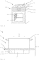
- the FIG. 1 shows a cooking device 1 according to the invention, which is designed here as part of a cooking appliance 100.
- the cooking appliance 1 or the cooking appliance 100 can be designed both as a built-in appliance and as a self-sufficient cooking appliance 1 or stand-alone cooking appliance 100.
- the cooking device 1 here comprises a hob 11 with four cooking zones 21.
- Each of the cooking zones 21 here has at least one heatable cooking area 31 for cooking food.
- a heating device 2 not shown here, is provided in total for each hotplate 21.
- the heating devices 2 are designed as induction heating sources and each have an induction device 12 for this purpose. But it is also possible that a cooking area 31 is not associated with any particular cooking area 21, but represents any location on the hob 11. In this case, the cooking area 31 may have a plurality of induction devices 12 and in particular a plurality of induction coils and be formed as part of a so-called full-surface induction unit.
- a pot can be placed anywhere on the hob 11, wherein during cooking only the corresponding induction coils are driven in the pot or are active.
- Other types of heaters 2 are also possible, such as gas, infrared or somehowsshreddedettin.
- the cooking device 1 can be operated here via the operating devices 105 of the cooking appliance 100.
- the cooking device 1 can also be designed as a self-sufficient cooking device 1 with its own operating and control device. Also possible is an operation via a touch-sensitive surface or a touch screen or remotely via a computer, a smartphone or the like.
- the cooking appliance 100 is here designed as a stove with a cooking chamber 103, which can be closed by a cooking chamber door 104.
- the cooking chamber 104 can be heated by various heating sources, such as a Um Kunststoffsagenmaschine.
- Other heating sources such as a top heat radiator and a bottom heat radiator and a microwave heat source or a vapor source and the like may be provided.
- the sensor device 3 can detect a variable, via which the temperature of a pot can be determined, which is turned off in the cooking area 31.
- each cooking area 31 and / or each cooking place 21 can be assigned a sensor device 3.
- the sensor device 3 is operatively connected to a control device 106 here.
- the control device 106 is designed to control the heating devices 2 as a function of the parameters detected by the sensor device 3.
- the cooking device 1 is preferably designed for an automatic cooking operation and has various automatic functions.
- a soup can be boiled briefly and then kept warm, without a user having to supervise the cooking process or set a heating level.
- he sets the pot with the soup on a hob 21 and selects the corresponding automatic function via the operating device 105, here z.
- the operating device 105 here z.
- the temperature of the pot bottom is determined during the cooking process.
- the control device 106 sets the heating power of the heating device 2 accordingly.
- the temperature of the bottom of the pot is monitored continuously, so that when the desired temperature or when boiling the soup, the heating power is regulated down.
- the automatic function it is also possible by the automatic function to perform a longer cooking process at one or more different desired temperatures, for. B. to slowly let rice pudding draw.
- a cooking device 1 is shown in a sectional side view very schematic.
- the cooking device 1 here has a carrier device 5 designed as a glass ceramic plate 15.
- the glass ceramic plate 15 may in particular be designed as a ceramic hob or the like or at least comprise such. Also possible are other types of support means 5.
- On the glass ceramic plate 15 is here a cookware or food containers 200, such as a pot or a pan, in which food or food can be cooked.
- a sensor device 3 is provided which detects heat radiation in a detection region 83 here.
- the detection area 83 is provided in the installed position of the cooking device 1 above the sensor device 3 and extends upward through the glass ceramic plate 15 to the food container 200 and beyond, if there is no food container 200 is placed there.
- an induction device 12 for heating the cooking area 31 is attached below the glass ceramic plate 15, an induction device 12 for heating the cooking area 31 is attached.
- the induction device 12 is here annular and has in the middle a recess in which the sensor device 3 is mounted.
- Such an arrangement of the sensor device 3 has the advantage that it is still in the detection range 83 of the sensor device even if the food container 200 is not centered on the cooking point 21.
- the sensor device 3 may also not be arranged centrally in the induction device. If an induction device has, for example, a dual-circuit induction coil, then at least one sensor device 3 can be arranged in a space provided between the two induction coils of the induction device.
- the FIG. 3 shows a schematic cooking device 1 in a sectional side view.
- the cooking device 1 has a glass ceramic plate 15, below which the induction device 12 and the sensor device 3 are mounted.
- the sensor device 3 has a first sensor unit 13 and another sensor unit 23. Both sensor units 13, 23 are suitable for non-contact detection of thermal radiation and designed as a thermopile or thermopile.
- the sensor units 13, 23 are each equipped with a filter device 43, 53 and provided for detecting heat radiation emanating from the cooking area 31.
- the thermal radiation emanates, for example, from the bottom of a food container 200, penetrates the glass ceramic plate 15 and reaches the sensor units 13, 23.
- the sensor device 3 is advantageously mounted directly underneath the glass ceramic plate 15 in order to maximize the proportion of heat radiation emanating from the cooking region 31 without great losses to be able to capture.
- the sensor units 13, 23 are provided close to the glass ceramic plate 15.
- a magnetic shielding device 4 which consists of a ferrite body 14 here.
- the ferrite body 14 is designed here essentially as a hollow cylinder and surrounds the sensor units 13, 23 in an annular manner Shielding device 4 shields the sensor device 3 against electromagnetic interactions and in particular against the electromagnetic field of the induction device 12 from. Without such shielding, the magnetic field generated by induction device 12 during operation could undesirably heat parts of sensor device 3 as well, resulting in unreliable temperature sensing and inferior measurement accuracy.
- the magnetic shielding device 4 thus considerably improves the accuracy and reproducibility of the temperature detection.
- the magnetic shielding device 4 may also consist at least in part of at least one at least partially magnetic material and an at least partially electrically non-conductive material.
- the magnetic material and the electrically non-conductive material may be arranged alternately and in layers. Also possible are other materials or materials which have at least partially magnetic properties and also have electrically insulating properties or at least low electrical conductivity.
- the sensor device 3 has at least one optical screen device 7, which is provided to shield radiation influences and in particular heat radiation, which act on the sensor units 13, 23 from outside the detection zone 83.
- the optical shield device 7 is designed here as a tube or a cylinder 17, wherein the cylinder 17 is hollow and the sensor units 13, 23 surrounds approximately annular.
- the cylinder 17 is made of stainless steel here. This has the advantage that the cylinder 17 has a reflective surface which reflects a large proportion of the much heat radiation or absorbs as little heat radiation as possible. The high reflectivity of the surface on the outside of the cylinder 17 is particularly advantageous for the shielding against thermal radiation.
- the high reflectivity of the surface on the inside of the cylinder 17 is also advantageous in order to direct thermal radiation from (and in particular only out) the detection area 83 to the sensor units 13, 23.
- the optical screen device 7 can also be configured as a wall, which surrounds the sensor device 13, 23 at least partially and preferably annularly.
- the cross section may be round, polygonal, oval or rounded. Also possible is a configuration as a cone.
- an insulation device 8 for thermal insulation is provided, which is arranged between the optical shield device 7 and the magnetic shielding device 4.
- the insulation device 8 consists here of an air layer 18, which is between the ferrite 14 and the cylinder 17.
- the insulation device 8 in particular a heat conduction from the ferrite 14 to the cylinder 17 is counteracted.
- the insulation device 8 has, in particular, a thickness of between approximately 0.5 mm and 5 mm and preferably a thickness of 0.8 mm to 2 mm and particularly preferably a thickness of approximately 1 mm.
- the isolation device 8 may also be at least one medium with a correspondingly low heat conduction, such. B. include a foam material and / or a polystyrene plastic or other suitable insulating material.
- the sensor units 13, 23 are arranged here in a thermally conductive manner on a thermal compensation device 9 and in particular are coupled in a thermally conductive manner to the thermal compensation device 9.
- the thermal compensation device 9 has for this purpose two coupling devices 29, which are formed here as depressions, in which the sensor units 13, 23 are embedded accurately. This ensures that the sensor units 13, 23 are at a common and relatively constant temperature level.
- the thermal compensation device 9 ensures a homogeneous temperature of the sensor unit 13, 23, when it heats up during operation of the cooking device 1. An unequal own temperature can lead to artefacts during the detection, in particular in the case of sensor units 13, 23 designed as thermopiles.
- a spacing between cylinder 17 and thermal compensation device 9 is provided.
- the copper plate 19 may also be provided as the bottom 27 of the cylinder 17.
- the thermal compensation device 9 is designed here as a solid copper plate 19.
- the thermal compensation device 9 is also possible at least in part another material with a correspondingly high heat capacity and / or a high thermal conductivity.
- the sensor device 3 here has a radiation source 63, which can be used to determine the reflection properties of the measuring system or the emissivity of a food container 200.
- the radiation source 63 is embodied here as a lamp 111, which emits a signal in the wavelength range of the infrared light and the visible light.
- the radiation source 63 may also be formed as a diode or the like.
- the lamp 111 is used here in addition to the reflection determination for signaling the operating state of the cooking device 1.
- a region of the thermal compensation device 9 or the copper plate 19 is formed as a reflector 39.
- the copper plate 19 has a concave-shaped depression, in which the lamp 111 is arranged.
- the copper plate 19 is also coated with a gold-containing coating to increase the reflectivity.
- the gold-containing layer has the advantage that it also protects the thermal compensation device 9 from corrosion.
- the thermal compensation device 9 is attached to a holding device 10 designed as a plastic holder.
- the holding device 10 has a connecting device 20, not shown here, by means of which the holding device 10 can be latched to a support means 30.
- the support device 30 is formed here as a printed circuit board 50. On the support means 30 and the circuit board 50 also other components may be provided, such. B electronic components, control and computing devices and / or mounting or mounting elements.
- a sealing device 6 is provided between the glass ceramic plate 15 and the induction device 12, which is designed here as a micanite layer 16.
- the micanite layer 16 is used for thermal insulation, so that the induction device 12 is not heated by the heat of the cooking area 31.
- a micanite layer 16 for thermal insulation between the ferrite body 14 and the glass-ceramic plate 15 is provided here. This has the advantage that the heat transfer from the hot in the glass ceramic plate 15 to the ferrite 14 is severely limited. As a result, hardly any heat emanates from the ferrite body 14, which could be transmitted to the insulation device 8 or the optical screen device. The micanite layer 16 thus counteracts an undesirable heat transfer to the sensor device 3, which increases the reliability of the measurements.
- the microlayer 16 seals the sensor device 3 dust-tight against the remaining regions of the cooking device 1.
- the micanite layer 16 has a thickness between about 0.2 mm and 4 mm, preferably from 0.2 mm to 1.5 mm and particularly preferably a thickness of 0.3 mm to 0.8 mm.
- the cooking device 1 has on the underside a cover 41, which is designed here as an aluminum plate and covers the Indu Vietnameseseicardi 12.
- the covering device 41 is connected to a housing 60 of the sensor device 3 via a screw connection 122.
- the sensor device 3 is arranged elastically relative to the glass ceramic plate 15.
- a damping device 102 is provided which has a spring device 112 here.
- the spring device 112 is connected at a lower end to the inside of the housing 60 and at an upper end to the printed circuit board 50.
- the spring device 112 presses the printed circuit board 50 with the ferrite body 14 and the micanite layer 16 mounted thereon upwards against the glass-ceramic plate 15.
- Such an elastic arrangement is particularly advantageous since the sensor device 3 should be arranged as close as possible to the glass ceramic plate 15 for metrological reasons. This directly adjacent arrangement of the sensor device 3 on the glass ceramic plate 15 could cause damage to the glass ceramic plate 15 in the event of impacts or impacts. Due to the elastic reception of the sensor device 3 relative to the carrier device 5, shocks or impacts are damped on the glass ceramic plate 15 and thus reliably prevent such damage.
- the first sensor unit 13 detects heat radiation emanating from the bottom of the pot as mixed radiation together with the heat radiation which is emitted by the glass-ceramic plate 15.
- the portion of the radiation output emanating from the glass ceramic plate 15 is calculated out of the mixed radiation power.
- the other sensor unit 23 is provided to detect only the heat radiation of the glass-ceramic plate 15.
- the other sensor unit 23 has a filter device 53, which transmits essentially only radiation having a wavelength greater than 5 ⁇ m to the sensor unit 23. The reason for this is that radiation with a wavelength greater than 5 microns is not or hardly transmitted by the glass ceramic plate 15.
- the other sensor unit 23 thus essentially detects the heat radiation emitted by the glass ceramic plate 15. With the knowledge of the portion of the heat radiation, which is emitted from the glass ceramic plate 15, can be determined in per se known, the proportion of heat radiation, which emanates from the bottom of the pot.
- the first sensor unit 13 is equipped with a filter device 43 which is very permeable to radiation in this wavelength range, while the filter device 43 substantially reflects radiation from other wavelength ranges.
- the filter devices 43, 53 are here each formed as an interference filter 433 and in particular designed as a bandpass filter or as a long-pass filter.
- a detection of the radiation in the wavelength range between 3 .mu.m and 5 .mu.m and in particular in the range of 3.1 .mu.m to 4.2 .mu.m be provided, wherein the each sensor unit and filter device is then respectively formed or adapted accordingly.
- the determination of a temperature from a specific radiant power is a known method.
- the decisive factor is that the emissivity of the body is known, from which the temperature is to be determined. In the present case, therefore, the emissivity of the pot bottom must be known or determined for a reliable temperature determination.
- the sensor device 3 here has the advantage that it is designed to determine the emissivity of a Gargut variousers 200. This is particularly advantageous, since thus any cookware can be used and not just a specific food container whose emissivity must be known in advance.
- the lamp 111 emits a signal, in particular a light signal, which has a proportion of heat radiation in the wavelength range of the infrared light.
- the radiant power or thermal radiation of the lamp 111 passes through the glass ceramic plate 15 on the bottom of the pot and is partially reflected there and partially absorbed.
- the radiation reflected from the bottom of the pot passes through the glass-ceramic plate 15 back to the sensor device 3, where it is detected by the first sensor unit 13.
- the own thermal radiation of the pot bottom and the thermal radiation of the glass ceramic plate 15 reach the first sensor unit 13.
- the lamp 111 is switched off and only the heat radiation of the pot bottom and the glass ceramic plate 15 is detected .
- the proportion of the reflected signal radiation, from which the emissivity of the pot bottom can be determined, then arises in principle as a difference from the previously detected total radiation with the lamp 111 switched on minus the heat radiation of the pot bottom and the glass ceramic plate with the lamp 111 switched off.
- At least one reference value with regard to reflected radiation and the associated emissivity is deposited in a memory unit which cooperates with the sensor device and is not shown in the figures, wherein the memory unit can be arranged, for example, on the printed circuit board 50.
- the respective actual emissivity of the pot bottom can then be determined based on a comparison of the reflected signal radiation with the at least one reference value.
- the proportion of the signal radiation absorbed by the bottom of the pot is determined. This results according to methods known per se from the radiation power emitted by the lamp 111 less the signal radiation reflected from the bottom of the pot.
- the radiation power of the lamp 111 is either fixed and thus known or is, for example, by a measurement with the other sensor unit 23rd certainly.
- the other sensor unit 23 detects a wavelength range of the signal radiation, which is almost completely reflected by the glass ceramic plate 15.
- the emitted radiation power can be determined in a very suitable approximation, whereby inter alia a wavelength dependence of the radiation line or the spectrum of the lamp 111 must be taken into account.
- the degree of absorption of the pot bottom can be determined in a known manner. Since the absorption capacity of a body corresponds in principle to the emissivity of a body, the desired emissivity can be derived from the degree of absorption of the pot bottom. With the knowledge of the emissivity and the amount of thermal radiation, which emanates from the bottom of the pot, the temperature of the pot bottom can be determined very reliably.
- the emissivity is preferably continuously redefined in the shortest possible intervals. This has the advantage that a subsequent change in the emissivity does not lead to a falsified measurement result.
- a change in the emissivity may occur, for example, when the cookware bottom has different emissivities and is displaced on the cooking surface 21. Different emissivities are very common in cookware trays observed because z. B. already light soiling, corrosion or even different coatings or coatings can have a major impact on the emissivity.
- the lamp 111 is also used here for signaling the operating state of the cooking device 1 in addition to the determination of the emissivity or the determination of the reflection behavior of the measuring system.
- the signal of the lamp 111 also includes visible light, which is perceptible by the glass-ceramic plate 15.
- the lamp 111 indicates to a user that an automatic function is in operation.
- Such an automatic function can, for. B. be a cooking operation, in which the heater 2 is controlled automatically in dependence of the determined pot temperature. This is particularly advantageous because the lighting up of the lamp 111 does not confuse the user. The user knows from experience that the lighting is an operation indicator and belongs to the normal appearance of the cooking device 1.
- a flash of the lamp 111 is not a malfunction and the cooking device 1 may not work properly.
- the lamp 111 may also light up in a certain duration and at certain intervals. It is possible z. B. also that different operating states can be output via different flashing frequencies. Different signals are also possible via different on / off sequences.
- a sensor device 3 with a radiation source 63 which is suitable for displaying at least one operating state, is provided for each cooking point 21 or each (possible) cooking region 31.
- At least one arithmetic unit may be provided for the necessary calculations for determining the temperature and for the evaluation of the detected variables.
- the arithmetic unit can be at least partially provided on the circuit board 50.
- the control device 106 it is also possible, for example, for the control device 106 to be designed accordingly, or at least one separate arithmetic unit is provided.
- the FIG. 4 shows a development in which below the glass ceramic plate 15, a security sensor 73 is attached.
- the safety sensor 73 is designed here as a temperature-sensitive resistor, such as a thermistor, in particular an NTC sensor, and thermally conductively connected to the glass ceramic plate 15.
- the safety sensor 73 is provided here to be able to detect a temperature of the cooking area 31 and in particular of the glass ceramic plate 15. If the temperature exceeds a certain value, there is a risk of overheating and the heaters 2 are switched off.
- the safety sensor 73 is operatively connected to a safety device, not shown here, which can trigger a safety state depending on the detected temperature.
- a security condition has z. B. the shutdown of the heaters 2 and the cooking device 1 result.
- the safety sensor 73 is assigned here as a further sensor unit 33 of the sensor device 3.
- the values detected by the safety sensor 73 are also taken into account for the determination of the temperature by the sensor device 3.
- the values of the safety sensor 73 are used. So z. B. the temperature, which was determined by means of the other sensor unit 23 on the detected thermal radiation, are compared with the temperature detected by the safety sensor 73. This adjustment can on the one hand serve to control the function of the sensor device 3, but on the other hand can also be used for a tuning or adjustment of the sensor device 3.
- a sensor device 3 is likewise shown, in which a safety sensor 73 is assigned as a further sensor unit 33 to the sensor device 3. Unlike the one in the FIG. 4 described embodiment, but no other sensor unit 23 is provided here. The task of the other sensor unit 23 is taken over here by the safety sensor 73.
- the safety sensor 73 is used to determine the temperature of the glass ceramic plate 15. For example, with knowledge of this temperature from the thermal radiation, which detects the first sensor unit 13, the proportion of a pot bottom can be determined.
- the other sensor unit 23 may be referred to as a second sensor unit.
- the further sensor unit 33 may be referred to as a third sensor unit. In the embodiment according to Fig. 5 only the first sensor unit and the third sensor unit are provided.
- FIG. 6 Another embodiment of a cooking device 1 is in the FIG. 6 shown.
- a common sealing device 6 for the induction device 12 and the ferrite body 14 of the sensor device 3 is provided.
- the sealing device 6 is designed as a micanite layer 16 which has a recess in the detection area 83 of the sensor device 3.
- the FIG. 7 shows a schematic, magnetic shielding 4, which is formed as a hollow, cylindrical ferrite body 14.
- a schematic, magnetic shielding 4 which is formed as a hollow, cylindrical ferrite body 14.
- the wall of the ferrite body 14 has a thickness of about 1 mm to 10 mm and in particular from 2 mm to 5 mm, and particularly preferably from 2.5 mm to 4 mm and in particular of 3 mm or more.
- FIG. 8 is an optical shield device 7 shown schematically, which is designed here as a cylinder 17.
- the cylinder has here three locking devices 80, which are suitable for connection to a holding device 10.
- a thermal compensation device 9 is in the FIG. 9 shown.
- the thermal compensation device 9 is designed as a copper plate 19.
- the copper plate has a thickness of 0.5 mm to 4 mm or even 10 mm or more, and more preferably from 0.8 mm to 2 mm, and more preferably 1 mm or more.
- the copper plate 19 here has two coupling devices 29.
- the coupling device 29 is suitable and provided to receive a sensor unit 13, 23 thermally conductive.
- the copper plate 19 has a reflector device 39, which can reflect the radiation of a radiation source 63 and, in particular, can focus.
- FIG. 10 shows a holding device 10, which is designed as a plastic holder.
- the holding device 10 preferably has a thickness between 0.3 mm and 3 mm or even 6 mm, and particularly preferably a thickness of 1 mm or more.
- the holding device 10 includes, for example, three connecting devices, of which only two connecting devices 20 are visible in the figure, by means of which the holding device 10 z. B. is connectable to a support device 30.
- the holding device 10 on three receiving devices 40, which are formed here as webs.
- the recording devices 40 are suitable for receiving the optical screen device 7 and arranging it at a defined distance from the magnetic shielding device 4. To carry out contacts receiving openings 70 are provided.
- the holding device 10 may also have further, not shown receptacles 40 which z. B.
- Such receiving devices 40 are in particular for the defined arrangement of a magnetic Shielding device 4, an optical shield device 7, a thermal compensation device 9, an insulation device 8 and / or a support device 30 is provided.
- a sensor unit 13 for non-contact detection of heat radiation is listed.
- the sensor unit 13 is designed as a thermopile or thermopile.
- the sensor unit 13 has contacts in order to connect them, for example, to a printed circuit board 50 or board.
- a filter device 43 is arranged here.
- FIG. 12a shows a formed as a thermopile sensor unit 13 with a filter device 43 in a sectioned, schematic side view.
- the filter device 43 is arranged here on the region in which the thermal radiation impinges on the sensor unit 13 and is detected.
- the filter device 43 is here attached to the sensor unit 13 with an adhesive connection means 430 in a thermally conductive manner.
- the connecting means 430 here is an adhesive with a thermal conductivity of at least 1 W m -1 K -1 (W / (mK)) and preferably of 0.5 W m -1 K -1 (W / (mK)). Also possible and preferred is a thermal conductivity of more than 4 W m -1 K -1 (W / (mK)).
- heat can be dissipated from the filter device 43 to the sensor unit 43.
- the dissipation of the heat prevents the sensor unit 13 from detecting the self-heat of the filter device 43, which would lead to a falsified measurement result.
- the heat from the filter device 43 via the sensor unit 13 can also be forwarded to the thermal compensation device 9 or the copper plate 19.
- Such indirect dissipation of the heat from the filter device 43 via the sensor unit 13 to the copper plate 19 is also particularly favorable since the copper plate 19 has a high heat capacity.
- the adhesive may be, for example, a thermosetting, one-component, solvent-free silver-filled epoxy conductive adhesive. Due to the proportion of silver or silver-containing compounds a very favorable thermal conductivity is achieved. Also possible is a proportion of other metals or metal compounds with a corresponding thermal conductivity. Such an adhesive ensures a thermally conductive connection, which is durable and stable even at the temperatures to be expected in a cooking device 1.
- the filter device 43 is designed as an interference filter 433 and here has four filter layers 432 with a different refractive index and with dielectric properties. In this case, filter layers 432 with higher and lower refractive indices are alternately stacked and connected.
- the filter layers 432 are, in particular, very thin, preferably a few nanometers to 25 nm.
- the carrier layer for the filter layers 432 here is a filter base 431 made of a silicon-containing material with a thickness of more than 0.2 mm.
- the filter device 43 is designed for this purpose and capable of transmitting a wavelength range in the infrared spectrum and substantially reflecting radiation outside this range.
- FIG. 12b shows a further embodiment of a sensor unit 13 with a filter device 43, wherein the filter device 43 is glued here only partially on the sensor device 13.
- the region in which the heat radiation strikes and is detected on the sensor unit 13 is surrounded here by a raised edge region.
- the connecting means 430 was applied only in an edge region. This has the advantage that the heat radiation to be detected does not have to pass through the connection means 430 before it strikes the sensor unit 13.
- a sensor device 3 is shown in a plan view. For clarity and distinctiveness, some parts or areas are shaded. It can be clearly seen that the sensor device 3 has a concentric structure according to the onion shell principle. Inside there is a thermal compensation device 9 or a copper plate 19, on which two sensor units 13, 23 and designed as a lamp 111 radiation source 63 are arranged. So that no unwanted heat radiation from the side of the sensor units 13, 23 is incident, the sensor units 13, 23 are surrounded by an optical screen device 7 and a cylinder 17. The cylinder 17 is spaced from the copper plate 19, so that as possible no heat transfer between the cylinder 17 and copper plate 19 can take place. The cylinder 17 is surrounded by a magnetic shielding device 4 and a ferrite body 14, respectively. The ferrite body 14 represents the outermost layer of the sensor device 3 and shields it against electromagnetic interactions.
- the sensor device 3 is preferably provided as close as possible below a carrier device 5, a sealing device 6 or a micanite layer 16 lies on the ferrite body 14, which considerably reduces a heat transfer from the carrier device 5 to the ferrite body 14.
- an insulation device 8 is formed between the ferrite body 14 and the cylinder 17, an insulation device 8 is formed.
- the insulation device 8 is here an air layer 18.
- the air layer 18 counteracts a heat transfer from the ferrite body 14 to the cylinder 17.
- the sensor units 13, 23 in the interior of the sensor device 3 are thus very effective against interference, such.
- B. a magnetic field of an induction device 12, heat radiation from outside the detection range 83 and heating by heat conduction, protected.
- Such a configured, shell-like arrangement of the listed components significantly increases the reliability of the measurements performed with the sensor device 3.
- FIG. 14 shows a sensor device 3 in an exploded view.
- the items are here shown spatially separated from each other, whereby the arrangement of the items within the sensor device 3 is clearly visible. Also the concentric or onion-peel-like Construction is easy to recognize here. In addition to an improved measurement accuracy, such a structure also allows a particularly production-friendly and cost-effective installation of the sensor device 3.
- a sensor unit 13, 23 may already be adhesively bonded to a filter device 43, 53 in a thermally conductive manner.
- the circuit board 50 may already be partially equipped with electronic components prior to assembly. Preferably z. B. the radiation source 63 already contacted with the circuit board 50.
- the holding device 10 designed as a plastic holder is first mounted on the supporting device 30 designed as a printed circuit board 50.
- the holding device 10 at least one connecting device 20, not shown here, which is connected to the circuit board 50 and z. B. can be locked.
- a holding device 10 with three connecting devices 20 is in the FIG. 10 shown.
- the provided here as a copper plate 19 thermal compensation device 9 is inserted into the holding device 10.
- the sensor units 13, 23 designed as thermopiles or thermopiles are then passed through receiving openings 70 in the copper plate 19, the holding device 10 and the printed circuit board 50.
- the mounting of the holding device 10, the copper plate 19 and the sensor units 13, 23 can also be performed in any other order. So z. B. first inserted the copper plate 19 in the holding device 10, then the sensor units 13, 23 inserted and subsequently the holding device 10 is locked to the circuit board 50. The contacting of the sensor units 13, 23 with the printed circuit board 50 can be done at any time during assembly.
- the contacting of the radiation source 63 designed as a lamp 111 with the printed circuit board 50 can likewise take place at any desired time of assembly. It is preferred to contact the lamp 111 first with the printed circuit board 50 and then to start with the mounting option described above.
- the optical screen device 7 designed as a cylinder 17.
- the cylinder 17 has three latching devices 80, which are latched to the three receiving devices 40 of the holding device 10.
- the holding device 10 preferably has a further, not shown here receiving device 40, which may be formed as a recess, survey, web and / or annular groove or the like.
- the sealing device 6 designed as micanite layer 16 is fastened to the magnetic shielding device 4.
- Other suitable mounting sequences for the cylinder 17, the ferrite body 14 and the sealing device 6 may be provided.
Description
Die vorliegende Erfindung betrifft eine Kocheinrichtung, welche insbesondere zur Zubereitung von Speisen vorgesehen ist. Die Kocheinrichtung umfasst wenigstens ein Kochfeld mit wenigstens einer Kochstelle und wenigstens eine zur Beheizung wenigstens eines Kochbereiches vorgesehene HeizeinrichtungThe present invention relates to a cooking device, which is provided in particular for the preparation of food. The cooking device comprises at least one hob with at least one cooking point and at least one heating device provided for heating at least one cooking area
Im Stand der Technik sind Kocheinrichtungen bekannt geworden, die Automatikfunktionen anbieten. Voraussetzung für einen solchen Automatikbetrieb einer Kocheinrichtung ist mitunter eine Erfassung verschiedener Parameter, welche für den Garvorgang charakteristisch sind, wie z. B. die Temperatur des Gargutbehälters und insbesondere des Topfbodens. In Abhängigkeit der erfassten Parameter werden dann die Automatikfunktion und insbesondere die Heizleistung der Kocheinrichtung gesteuert. Die Heizquelle muss dabei so gesteuert werden, dass z. B. eine unerwünschte Überhitzung des Gargutes vermieden wird. Daher ist die Zuverlässigkeit bzw. die Genauigkeit der erfassten Parameter entscheidend für die Funktionalität der Automatikfunktion.In the prior art cooking appliances have become known that offer automatic functions. A prerequisite for such an automatic operation of a cooking device is sometimes a detection of various parameters that are characteristic of the cooking process, such. B. the temperature of the food container and in particular the pot bottom. Depending on the detected parameters then the automatic function and in particular the heating power of the cooking device are controlled. The heat source must be controlled so that z. B. an undesirable overheating of the food is avoided. Therefore, the reliability or accuracy of the detected parameters is crucial to the functionality of the automatic function.
Im Stand der Technik sind zur Ermittlung von Temperaturen bei Gar- und Kochvorgängen unterschiedliche Techniken bekannt. So gibt es Kocheinrichtungen mit wenigstens einer Sicherheitssensoreinheit zur Erfassung wenigstens einer charakteristischen Größe für Temperaturen. Eine Steuerung der Kocheinrichtungen schaltet diese ab, wenn eine solche Sicherheitssensoreinheit z. B. eine unzulässig hohe Temperatur ermittelt. eine derartige Sicherheitssensoreinheit ist in der Regel als ein temperaturempfindlicher Widerstand ausgebildet und thermisch leitend mit der Glaskeramikplatte verbunden.In the prior art, different techniques are known for determining temperatures during cooking and cooking operations. Thus, there are cooking devices with at least one safety sensor unit for detecting at least one characteristic quantity for temperatures. A control of the cooking devices switches these off when such a safety sensor unit z. B. determines an impermissibly high temperature. such a safety sensor unit is usually designed as a temperature-sensitive resistor and thermally conductively connected to the glass ceramic plate.
Darüber hinaus sind auch Vorrichtungen bekannt geworden, welche die Temperatur an der Unterseite eines Gargutbehälters berührungslos ermitteln. So sieht z. B. die
Aus der
Die
Die
Es ist daher die Aufgabe der vorliegenden Erfindung, eine Kocheinrichtung mit einer Sensoreinrichtung zur Verfügung zu stellen, welche eine zuverlässige Erfassung von Temperaturen, insbesondere der Temperatur eines Gargutbehälters, ermöglicht.It is therefore the object of the present invention to provide a cooking device with a sensor device which enables reliable detection of temperatures, in particular the temperature of a food container.
Diese Aufgabe wird durch eine Kocheinrichtung mit den Merkmalen des Anspruchs 1 gelöst. Bevorzugte Weiterbildungen sind Gegenstand der Unteransprüche. Weitere Vorteile und Merkmale ergeben sich aus der allgemeinen Beschreibung und aus der Beschreibung der Ausführungsbeispiele.This object is achieved by a cooking device with the features of
Die erfindungsgemäße Kocheinrichtung umfasst wenigstens ein Kochfeld mit wenigstens einer Kochstelle und wenigstens eine zur Beheizung wenigstens eines Kochbereiches vorgesehene Heizeinrichtung. Dabei ist wenigstens eine Sicherheitseinrichtung vorgesehen, welcher wenigstens eine Sicherheitssensoreinheit zugeordnet ist. Die Sicherheitssensoreinheit ist zur Erfassung wenigstens einer charakteristischen Größe für Temperaturen ausgebildet. Weiterhin ist wenigstens eine Steuereinrichtung vorgesehen. Wenigstens eine Sensoreinrichtung ist zur Erfassung wenigstens einer charakteristischen Größe für wenigstens eine Temperatur des Kochbereichs vorgesehen. Die Steuereinrichtung ist wenigstens teilweise dazu ausgebildet und eingerichtet, die Heizeinrichtung in Abhängigkeit der von der Sensoreinrichtung erfassten Größe zu steuern. Der Sensoreinrichtung sind wenigstens eine erste Sensoreinheit und wenigstens eine weitere Sensoreinheit zugeordnet. Die erste Sensoreinheit ist zur berührungslosen Erfassung von Wärmestrahlung ausgebildet und eingerichtet. Die Sicherheitssensoreinheit ist der Sensoreinrichtung als die weitere Sensoreinheit zugeordnet.The cooking appliance according to the invention comprises at least one hob with at least one cooking point and at least one heating device provided for heating at least one cooking area. In this case, at least one safety device is provided, which is associated with at least one safety sensor unit. The safety sensor unit is designed to detect at least one characteristic variable for temperatures. Furthermore, at least one control device is provided. At least one sensor device is provided for detecting at least one characteristic variable for at least one temperature of the cooking area. The control device is at least partially designed and configured to control the heating device as a function of the variable detected by the sensor device. At least one first sensor unit and at least one further sensor unit are assigned to the sensor device. The first sensor unit is designed and set up for non-contact detection of thermal radiation. The safety sensor unit is assigned to the sensor device as the further sensor unit.
Die erfindungsgemäße Kocheinrichtung hat viele Vorteile, da sie einen einfachen, relativ kostengünstigen Aufbau und zuverlässigen Betrieb ermöglicht.The cooking device according to the invention has many advantages, as it allows a simple, relatively inexpensive construction and reliable operation.
Die Erfindung macht sich zunutze, dass regelmäßig Sicherheitssensoreinheiten verbaut werden, um beispielsweise im Schadensfalle eine Notabschaltung durchführen zu können. Die Steuerung schaltet eine Kocheinrichtung ab, wenn eine solche Sicherheitssensoreinheit z. B. eine unzulässig hohe Temperatur ermittelt. Eine solche Sicherheitssensoreinheit wird erfindungsgemäß genutzt, um auch für die Sensoreinrichtung Sensorsignale zu liefern. Dadurch kann eine einfache Kontroll- und Plausibilitätsfunktion realisiert werden, da eine solche Sicherheitssensoreinheit regelmäßig vorhanden ist. Es kann Aufwand eingespart werden, ohne Funktionalität einzubüßen.The invention makes use of the fact that safety sensor units are regularly installed in order to be able to carry out an emergency shutdown, for example, in the event of damage. The controller switches off a cooking device, if such a safety sensor unit z. B. determines an impermissibly high temperature. Such a safety sensor unit is used according to the invention to also supply sensor signals for the sensor device. As a result, a simple control and plausibility function can be realized, since such a safety sensor unit is regularly present. It can be saved effort, without losing functionality.
Vorzugsweise weist das Kochfeld wenigstens eine Trägereinrichtung auf, welche zum Positionieren wenigstens eines Gargutbehälters geeignet und ausgebildet ist. Die Trägereinrichtung umfasst vorzugsweise eine Glaskeramikplatte oder ist als eine solche ausgebildet. Die Sensoreinrichtung ist vorzugsweise in Einbaulage des Kochfeldes wenigstens teilweise unterhalb der Trägereinrichtung angeordnet. Die Sensoreinrichtung ist vorzugsweise in der Nähe und/oder in einem zentrischen Bereich der Heizeinrichtung vorgesehen. Die Sensoreinrichtung kann von der Heizeinrichtung wenigstens teilweise und insbesondere im Wesentlichen vollständig in wenigstens einer Ebene parallel zu der Ausrichtung der Trägereinrichtung umgeben sein.Preferably, the hob has at least one carrier device which is suitable and designed for positioning at least one Gargutbehälters. The carrier device preferably comprises or is designed as a glass ceramic plate. The sensor device is preferably arranged in the installation position of the hob at least partially below the carrier device. The sensor device is preferably provided in the vicinity and / or in a central region of the heater. The sensor device may be surrounded by the heating device at least partially and in particular substantially completely in at least one plane parallel to the orientation of the carrier device.
Die erste Sensoreinheit umfasst eine Thermosäule und vorzugsweise ein Thermopile oder ist ein solches ausgebildet.The first sensor unit comprises a thermopile and preferably a thermopile or is designed such.
Die weitere Sensoreinheit ist insbesondere dazu vorgesehen, eine Temperatur an der Unterseite der Trägereinrichtung zu erfassen. Dazu ist die weitere Sensoreinheit vorzugsweise an der Unterseite der Trägereinrichtung thermisch leitend angeordnet.The further sensor unit is in particular provided to detect a temperature at the underside of the carrier device. For this purpose, the further sensor unit is preferably arranged thermally conductive on the underside of the carrier device.
Die weitere Sensoreinheit kann als temperaturempfindlicher Widerstand oder als Thermoelement oder sonstiges temperaturempfindliches Element ausgebildet sein. Die weitere Sensoreinheit kann einen Thermistor, insbesondere einen Kaltleiter (PTC) und/oder Heißleiter (NTC), umfassen oder als ein solcher ausgebildet sein. Ein solcher weist einen durch Temperaturänderung reproduzierbaren veränderlichen Widerstand auf.The further sensor unit can be designed as a temperature-sensitive resistor or as a thermocouple or other temperature-sensitive element. The further sensor unit may comprise or be designed as a thermistor, in particular a thermistor (PTC) and / or thermistor (NTC). Such has a variable resistance reproducible by temperature change.
Weiterhin kann wenigstens eine andere Sensoreinheit vorgesehen sein, welche zur berührungslosen Erfassung von Wärmestrahlung ausgebildet und geeignet ist.Furthermore, at least one other sensor unit may be provided, which is designed and suitable for non-contact detection of thermal radiation.
Insgesamt ist wenigstens eine der Sensoreinheiten zur Kontrolle wenigstens einer der übrigen Sensoreinheiten geeignet und ausgebildet.Overall, at least one of the sensor units is suitable and designed to control at least one of the remaining sensor units.
Wenigstens eine Sensoreinheit ist dazu geeignet und ausgebildet, einen Sicherheitszustand auszulösen. In einem solchen Sicherheitszustand wird die Kocheinrichtung vorzugsweise abgeschaltet oder in einen Sicherheits- oder Notbetrieb versetzt. Als Sensoreinheit wird dazu insbesondere der als weitere Sensoreinheit dienende und/oder ausgebildete Sicherheitssensor eingesetzt.At least one sensor unit is suitable and designed to trigger a safety state. In such a safety state, the cooking device is preferably switched off or placed in a safety or emergency operation. In particular, the sensor unit serving as a further sensor unit and / or trained safety sensor is used.
Erfindungsgemäß weist die Sensoreinrichtung wenigstens eine Filtereinrichtung auf. Die Filtereinrichtung ist dazu ausgebildet und geeignet, elektromagnetische Strahlung in Abhängigkeit der Wellenlänge und/oder der Polarisation und/oder des Einfallswinkels zu reflektieren und/oder zu transmittieren. Besonders bevorzugt wirkt die Filtereinrichtung auf möglicherweise vorhandene unterschiedliche optische Sensoreinheiten unterschiedlich. Vorzugsweise umfasst die Heizeinrichtung wenigstens eine Induktionseinrichtung. Die Induktionseinrichtung kann eine, mehrere oder eine Vielzahl von Induktionsspulen umfassen. Die Sensoreinrichtung umfasst insbesondere wenigstens eine magnetische Abschirmeinrichtung. Die magnetische Abschirmeinrichtung dient insbesondere zur Abschirmung von elektromagnetischen Wechselwirkungen und ist insbesondere zur Abschirmung vor dem elektromagnetischen Feld der Induktionseinrichtung ausgebildet und geeignet.According to the invention, the sensor device has at least one filter device. The filter device is designed and suitable for reflecting and / or transmitting electromagnetic radiation as a function of the wavelength and / or the polarization and / or the angle of incidence. Particularly preferably, the filter device acts differently on possibly existing different optical sensor units. Preferably, the heating device comprises at least one induction device. The induction device may comprise one, several or a plurality of induction coils. The sensor device comprises in particular at least one magnetic shielding device. The magnetic shielding device is used in particular for shielding electromagnetic interactions and is designed and suitable in particular for shielding from the electromagnetic field of the induction device.
Es ist vorzugsweise wenigstens eine Dichtungseinrichtung insbesondere zur thermischen Isolierung vorgesehen. Insbesondere ist wenigstens ein Teil der Dichtungseinrichtung wenigstens teilweise zwischen der Trägereinrichtung und wenigstens einem Teil der Sensoreinrichtung und/oder der magnetischen Abschirmeinrichtung angeordnet. Die Dichtungseinrichtung besteht vorzugsweise aus einem wenig Wärme leitenden Material. Die Dichtungseinrichtung dient insbesondere auch zur Abdichtung vor Staub und auch zum Abhalten unerwünschter Strahlung.At least one sealing device, in particular for thermal insulation, is preferably provided. In particular, at least part of the sealing device is arranged at least partially between the carrier device and at least part of the sensor device and / or the magnetic shielding device. The sealing device preferably consists of a little heat-conducting material. The sealing device is also used in particular for sealing against dust and also for preventing unwanted radiation.
In allen Ausgestaltungen kann die Sensoreinrichtung wenigstens eine optische Schirmeinrichtung aufweisen. Die optische Schirmeinrichtung ist insbesondere wenigstens teilweise von der magnetischen Abschirmeinrichtung umgeben angeordnet.In all embodiments, the sensor device can have at least one optical screen device. The optical screen device is in particular at least partially surrounded by the magnetic shielding device.
Die Sensoreinrichtung umfasst wenigstens eine thermische Ausgleichseinrichtung, wobei die thermische Ausgleichseinrichtung insbesondere wenigstens eine Koppeleinrichtung aufweist, welche dazu geeignet und ausgebildet ist, wenigstens eine Sensoreinheit mit der thermischen Ausgleichseinrichtung wenigstens teilweise thermisch leitend zu verbinden.The sensor device comprises at least one thermal compensation device, wherein the thermal compensation device in particular has at least one coupling device which is suitable and designed to at least partially thermally conductively connect at least one sensor unit to the thermal compensation device.
Vorzugsweise weist die Sensoreinrichtung wenigstens eine Strahlungsquelle auf, welche wenigstens ein Signal insbesondere wenigstens auch im Wellenlängenbereich des Infrarotlichts und/oder des sichtbaren Lichts aussendet.Preferably, the sensor device has at least one radiation source which emits at least one signal, in particular at least also in the wavelength range of the infrared light and / or the visible light.
In allen Weiterbildungen weist die Sensoreinrichtung bevorzugt wenigstens eine Halteeinrichtung auf. Durch die Halteeinrichtung sind insbesondere wenigstens zwei Einheiten in einer definierten Anordnung zueinander aufnehmbar. Dabei sind die Einheiten vorzugsweise aus einer Gruppe von Einheiten entnommen, welche Gruppe Sensoreinheiten, magnetische Abschirmeinrichtungen, optische Schirmeinrichtungen, Isolierungseinrichtungen, Strahlungsquellen und thermische Ausgleichseinrichtungen und dergleichen mehr umfasst.In all developments, the sensor device preferably has at least one holding device. In particular, at least two units in a defined arrangement can be received by the holding device. In this case, the units are preferably taken from a group of units, which group more comprises sensor units, magnetic shielding devices, optical shielding devices, insulation devices, radiation sources and thermal compensation devices and the like.
Die Erfindung stellt eine sehr vorteilhafte Kocheinrichtung zur Verfügung. Dabei ist es möglich, die als sogenanntes Optikmodul ausgeführte Sensoreinrichtung durch einen Temperaturfühler (z. B. NTC), zu ergänzen, der insbesondere an der Unterseite der vorzugsweise als Glaskeramik ausgebildeten Trägereinrichtung angeordnet ist. Dabei liegt der Temperaturfühler bevorzugt an der Unterseite der vorzugsweise als Glaskeramik ausgebildeten Trägereinrichtung an, wobei der Temperaurfühler beispielsweise aufgeklebt oder durch geeignete Mittel angepresst bzw. angeklemmt sein kann. Damit ist neben der z. B. als Thermopile ausgeführten zweiten Sensoreinheit eine redundante Messung der Unterseitentemperatur der Glaskeramik der Trägereinrichtung möglich. Dieses zusätzliche Signal kann mit zur Berechnung der Bodentemperatur des Kochgeschirrs bzw. Gargefäßes herangezogen werden. Ein solcher Temperaturfühler als Sensoreinheit kann aus Sicherheitsgründen vorgesehen sein und nun entsprechend auch im normalen Betrieb genutzt werden.The invention provides a very advantageous cooking device. In this case, it is possible to supplement the sensor device embodied as a so-called optical module by a temperature sensor (eg NTC), which is arranged in particular on the underside of the carrier device, which is preferably designed as a glass ceramic. In this case, the temperature sensor is preferably located on the underside of the preferably designed as a glass ceramic support means, wherein the Temperaurfühler example, glued or pressed by suitable means or can be clamped. This is in addition to the z. B. designed as a thermopile second sensor unit a redundant measurement of the bottom temperature of the glass ceramic of the support device possible. This additional signal can be used to calculate the bottom temperature of the cookware or cooking vessel. Such a Temperature sensor as a sensor unit can be provided for security reasons and now be used accordingly in normal operation.
Vorzugsweise wird nur ein Thermopile als Sensoreinheit eingesetzt. Für die Bestimmung der Unterseitentemperatur der Glaskeramik wird vorzugsweise ein Temperaturfühler wie z. B. ein NTC verwendet. Der z. B. aus Sicherheitsgründen vorhandene Temperaturfühler wird nun im Betrieb nicht nur zu Sicherheitszwecken eingesetzt, sondern auch um beispielsweise Automatikfunktionen zu steuern.Preferably, only one thermopile is used as the sensor unit. For the determination of the bottom temperature of the glass ceramic is preferably a temperature sensor such. As an NTC used. The z. B. for safety reasons existing temperature sensor is now used in operation not only for security purposes, but also to control, for example, automatic functions.
Die insbesondere als Thermopile ausgeführte und berührungslos arbeitende Sensoreinheit dient zur Erfassung der Temperatur des Bodens des Kochgeschirrs und detektiert zunächst die Strahlungsmenge. Die von einer Oberfläche abgestrahlte Strahlung hängt von dem Emissionskoeffizienten und der Temperatur der Oberfläche ab. Wird bei Kocheinrichtungen mit Glaskeramikkochfeldern von unten gemessen, so sendet zum einen die Glaskeramik Wärmestrahlung aus und zum anderen sendet der Boden eines darauf positionierten Gargutbehälters bzw. Kochgeschirrs Wärmestrahlung aus. Der Emissionskoeffizient der Glaskeramik kann zuvor oder separat ermittelt und als bekannt vorausgesetzt werden. Der Emissionskoeffizient des Bodens eines darauf positionierten Gargutbehälters bzw. Kochgeschirrs hängt hingegen von dem Gargutbehälter und von dessen aktuellem Zustand ab. Durch Bestimmung des Reflexionsvermögens des Gargutbehälters, Bestimmung der Temperatur der Glaskeramik und durch Auswertung der erfassten Strahlungsmenge kann so die Temperatur des Bodens des Gargutbehälters abgeleitet werden.The sensor unit, which is designed in particular as a thermopile and works without contact, serves to detect the temperature of the bottom of the cookware and initially detects the amount of radiation. The radiation emitted by a surface depends on the emission coefficient and the temperature of the surface. Is measured in cooking facilities with glass ceramic hobs from below, so sends the glass ceramic heat radiation and on the other sends the bottom of a food container or cookware positioned thereon heat radiation. The emission coefficient of the glass ceramic can be determined previously or separately and assumed to be known. The emission coefficient of the bottom of a food container or cooking utensil positioned on the other hand depends on the food container and its current state. By determining the reflectivity of the Gargutbehälters, determining the temperature of the glass ceramic and by evaluating the detected radiation amount so the temperature of the bottom of the Gargutbehälters can be derived.
Weitere Vorteile und Merkmale der Erfindung ergeben sich aus den Ausführungsbeispielen, welche im Folgenden mit Bezug auf die beiliegenden Figuren erläutert werden.Further advantages and features of the invention will become apparent from the embodiments, which are explained below with reference to the accompanying figures.
In den Figuren zeigen:
Figur 1- eine schematische Darstellung einer erfindungsgemäßen Kocheinrichtung an einem Gargerät in perspektivischer Ansicht;
Figur 2- eine schematisierte Kocheinrichtung in einer geschnittenen Ansicht;
Figur 3- eine weitere Kocheinrichtung in einer schematischen, geschnittenen Ansicht;
Figur 4- eine weitere Ausgestaltung einer Kocheinrichtung in einer geschnittenen Ansicht;
Figur 5- eine andere Ausgestaltung einer Kocheinrichtung in einer geschnittenen Ansicht;
Figur 6- ein weiteres Ausführungsbeispiel einer Kocheinrichtung;
Figur 7- eine schematische Darstellung einer magnetischen Abschirmeinrichtung in perspektivischer Ansicht;
Figur 8- eine schematische, perspektivische Darstellung einer optischen Schirmeinrichtung;
Figur 9- eine schematische, perspektivische Darstellung einer thermischen Ausgleichseinrichtung;
Figur 10- eine schematische, perspektivische Darstellung einer Halteeinrichtung;
Figur 11- eine schematische, perspektivische Darstellung einer Sensoreinheit;
- Figur 12a
- eine schematisierte Sensoreinheit mit einer Filtereinrichtung in einer geschnittenen Darstellung;
- Figur 12b
- ein weiteres Ausführungsbeispiel einer Sensoreinheit mit einer Filtereinrichtung in einer geschnittenen Darstellung;
Figur 13- eine schematisierte Sensoreinrichtung in einer Draufsicht; und
Figur 14- eine Sensoreinrichtung in einer Explosionsdarstellung.
- FIG. 1
- a schematic representation of a cooking device according to the invention on a cooking appliance in a perspective view;
- FIG. 2
- a schematic cooking device in a sectional view;
- FIG. 3
- another cooking device in a schematic, sectional view;
- FIG. 4
- a further embodiment of a cooking device in a sectional view;
- FIG. 5
- another embodiment of a cooking device in a sectional view;
- FIG. 6
- another embodiment of a cooking device;
- FIG. 7
- a schematic representation of a magnetic shielding in perspective view;
- FIG. 8
- a schematic, perspective view of an optical shielding device;
- FIG. 9
- a schematic, perspective view of a thermal compensation device;
- FIG. 10
- a schematic, perspective view of a holding device;
- FIG. 11
- a schematic, perspective view of a sensor unit;
- FIG. 12a
- a schematic sensor unit with a filter device in a sectional view;
- FIG. 12b
- a further embodiment of a sensor unit with a filter device in a sectional view;
- FIG. 13
- a schematic sensor device in a plan view; and
- FIG. 14
- a sensor device in an exploded view.
Die
Die Kocheinrichtung 1 umfasst hier ein Kochfeld 11 mit vier Kochstellen 21. Jede der Kochstellen 21 weist hier wenigstens einen beheizbaren Kochbereich 31 zum Garen von Speisen auf. Zur Beheizung des Kochbereichs 31 ist insgesamt eine oder aber für jede Kochstelle 21 jeweils eine hier nicht dargestellte Heizeinrichtung 2 vorgesehen. Die Heizeinrichtungen 2 sind als Induktionsheizquellen ausgebildet und weisen dazu jeweils eine Induktionseinrichtung 12 auf. Möglich ist aber auch, dass ein Kochbereich 31 keiner bestimmten Kochstelle 21 zugeordnet ist, sondern einen beliebigen Ort auf dem Kochfeld 11 darstellt. Dabei kann der Kochbereich 31 mehrere Induktionseinrichtungen 12 und insbesondere mehrere Induktionsspulen aufweisen und als Teil einer sogenannten Vollflächeninduktionseinheit ausgebildet sein. Beispielsweise kann bei einem solchen Kochbereich 31 einfach ein Topf an einer beliebigen Stelle auf das Kochfeld 11 gestellt werden, wobei während des Kochbetriebes nur die entsprechenden Induktionsspulen im Bereich des Topfes angesteuert werden oder aktiv sind. Andere Arten von Heizeinrichtungen 2 sind aber auch möglich, wie z.B. Gas-, Infrarot- oder Widerstandsheizquellen.The
Die Kocheinrichtung 1 ist hier über die Bedieneinrichtungen 105 des Gargerätes 100 bedienbar. Die Kocheinrichtung 1 kann aber auch als autarke Kocheinrichtung 1 mit einer eigenen Bedien- und Steuereinrichtung ausgebildet sein. Möglich ist auch eine Bedienung über eine berührungsempfindliche Oberfläche oder einen Touchscreen oder aus der Ferne über einen Computer, ein Smartphone oder dergleichen.The
Das Gargerät 100 ist hier als ein Herd mit einem Garraum 103 ausgebildet, welcher durch eine Garraumtür 104 verschließbar ist. Der Garraum 104 kann durch verschiedene Heizquellen, wie beispielsweise eine Umluftheizquelle, beheizt werden. Weitere Heizquellen, wie ein Oberhitzeheizkörper und ein Unterhitzeheizkörper sowie eine Mikrowellenheizquelle oder eine Dampfquelle und dergleichen können vorgesehen sein.The
Weiterhin weist die Kocheinrichtung 1 eine hier nicht dargestellte Sensoreinrichtung 3 auf, welche zur Erfassung wenigstens einer wenigstens einen Zustand des Kochbereichs 31 charakterisierenden physikalischen Größe geeignet ist. Beispielsweise kann die Sensoreinrichtung 3 eine Größe erfassen, über welche die Temperatur eines Topfes bestimmt werden kann, der in dem Kochbereich 31 abgestellt ist. Dabei kann jedem Kochbereich 31 und/oder jeder Kochstelle 21 eine Sensoreinrichtung 3 zugordnet sein. Möglich ist aber auch, dass mehrere Kochbereiche 31 und/oder Kochstellen 21 vorgesehen sind, von denen aber nicht alle eine Sensoreinrichtung 3 aufweisen. Die Sensoreinrichtung 3 ist hier mit einer Steuereinrichtung 106 wirkverbunden. Die Steuereinrichtung 106 ist dazu ausgebildet, die Heizeinrichtungen 2 in Abhängigkeit der von der Sensoreinrichtung 3 erfassten Parameter zu steuern.Furthermore, the
Die Kocheinrichtung 1 ist bevorzugt für einen automatischen Kochbetrieb ausgebildet und verfügt über verschiedene Automatikfunktionen. Beispielsweise kann mit der Automatikfunktion eine Suppe kurz aufgekocht und anschließend warm gehalten werden, ohne dass ein Benutzer den Kochvorgang betreuen oder eine Heizstufe einstellen muss. Dazu stellt er den Topf mit der Suppe auf eine Kochstelle 21 und wählt über die Bedieneinrichtung 105 die entsprechende Automatikfunktion, hier z. B. ein Aufkochen mit anschließendem Warmhalten bei 60°C oder 70°C oder dgl.The
Mittels der Sensoreinrichtung 3 wird während des Kochvorgangs die Temperatur des Topfbodens ermittelt. In Abhängigkeit der gemessenen Werte stellt die Steuereinrichtung 106 die Heizleistung der Heizeinrichtung 2 entsprechend ein. Dabei wird die Temperatur des Topfbodens fortlaufend überwacht, sodass bei Erreichen der gewünschten Temperatur bzw. beim Aufkochen der Suppe die Heizleistung heruntergeregelt wird. Beispielsweise ist es durch die Automatikfunktion auch möglich, einen längeren Garvorgang bei einer oder mehreren verschiedenen gewünschten Temperaturen durchzuführen, z. B. um Milchreis langsam gar ziehen zu lassen.By means of the
In der
Die
Die Sensoreinrichtung 3 weist eine erste Sensoreinheit 13 und eine andere Sensoreinheit 23 auf. Beide Sensoreinheiten 13, 23 sind zur berührungslosen Erfassung von Wärmestrahlung geeignet und als Thermosäule bzw. Thermopile ausgebildet. Die Sensoreinheiten 13, 23 sind mit jeweils einer Filtereinrichtung 43, 53 ausgestattet und zur Erfassung von Wärmestrahlung, welche vom Kochbereich 31 ausgeht, vorgesehen. Die Wärmestrahlung geht beispielsweise vom Boden eines Gargutbehälters 200 aus, durchdringt die Glaskeramikplatte 15 und gelangt auf die Sensoreinheiten 13, 23. Die Sensoreinrichtung 3 ist vorteilhafterweise direkt unterhalb der Glaskeramikplatte 15 angebracht, um einen möglichst großen Anteil der vom Kochbereich 31 ausgehenden Wärmestrahlung ohne große Verluste erfassen zu können. Damit sind die Sensoreinheiten 13, 23 dicht unterhalb der Glaskeramikplatte 15 vorgesehen.The
Weiterhin ist eine magnetische Abschirmeinrichtung 4 vorgesehen, welche hier aus einem Ferritkörper 14 besteht. Der Ferritkörper 14 ist hier im Wesentlichen als ein hohler Zylinder ausgebildet und umgibt ringartig die Sensoreinheiten 13, 23. Die magnetische Abschirmeinrichtung 4 schirmt die Sensoreinrichtung 3 gegen elektromagnetische Wechselwirkungen und insbesondere gegen das elektromagnetische Feld der Induktionseinrichtung 12 ab. Ohne eine solche Abschirmung könnte das magnetische Feld, welches die Induktionseinrichtung 12 beim Betrieb erzeugt, in unerwünschter Weise auch Teile der Sensoreinrichtung 3 erwärmen und somit zu einer unzuverlässigen Temperaturerfassung und einer schlechteren Messgenauigkeit führen. Die magnetische Abschirmeinrichtung 4 verbessert somit die Genauigkeit und Reproduzierbarkeit der Temperaturerfassung erheblich.Furthermore, a
Die magnetische Abschirmeinrichtung 4 kann auch wenigstens zu einem Teil aus wenigstens einem wenigstens teilweise magnetischen Material und einem wenigstens teilweise elektrisch nicht-leitenden Material bestehen. Das magnetische Material und das elektrisch nicht-leitende Material können dabei abwechselnd und schichtartig angeordnet sein. Möglich sind auch andere Materialien bzw. Werkstoffe, welche wenigstens teilweise magnetische Eigenschaften aufweisen und zudem elektrisch isolierende Eigenschaften oder wenigstens eine geringe elektrische Leitfähigkeit aufweisen.The
Die Sensoreinrichtung 3 weist wenigstens eine optische Schirmeinrichtung 7 auf, welche dazu vorgesehen ist, Strahlungseinflüsse und insbesondere Wärmestrahlung abzuschirmen, die von außerhalb des Erfassungsbereichs 83 auf die Sensoreinheiten 13, 23 wirken. Dazu ist die optische Schirmeinrichtung 7 hier als eine Röhre oder ein Zylinder 17 ausgebildet, wobei der Zylinder 17 hohl ausgestaltet ist und die Sensoreinheiten 13, 23 etwa ringförmig umgibt. Der Zylinder 17 ist hier aus Edelstahl gefertigt. Das hat den Vorteil, dass der Zylinder 17 eine reflektive Oberfläche aufweist, welche einen großen Anteil der viel Wärmestrahlung reflektiert bzw. möglichst wenig Wärmestrahlung absorbiert. Die hohe Reflektivität der Oberfläche an der Außenseite des Zylinders 17 ist besonders vorteilhaft für die Abschirmung gegen Wärmestrahlung. Die hohe Reflektivität der Oberfläche an der Innenseite des Zylinders 17 ist auch vorteilhaft, um Wärmestrahlung aus (und insbesondere nur aus) dem Erfassungsbereich 83 zu den Sensoreinheiten 13, 23 hinzuleiten. Die optische Schirmeinrichtung 7 kann auch als eine Wandung ausgestaltet sein, welche die Sensoreinrichtung 13, 23 wenigstens teilweise und bevorzugt ringartig umgibt. Der Querschnitt kann rund, mehreckig, oval oder abgerundet sein. Möglich ist auch eine Ausgestaltung als Konus.The
Weiterhin ist eine Isolierungseinrichtung 8 zur thermischen Isolierung vorgesehen, welche zwischen der optischen Schirmeinrichtung 7 und der magnetischen Abschirmeinrichtung 4 angeordnet ist. Die Isolierungseinrichtung 8 besteht hier aus einer Luftschicht 18, welche sich zwischen dem Ferritkörper 14 und dem Zylinder 17 aufhält. Vorzugsweise findet kein Austausch mit der Umgebungsluft statt, um Konvektion zu vermeiden. Möglich ist aber auch ein Austausch mit der Umgebungsluft. Durch die Isolierungseinrichtung 8 wird insbesondere einer Wärmeleitung vom Ferritkörper 14 zum Zylinder 17 entgegen gewirkt. Zudem ist der Zylinder 17, wie bereits oben erwähnt, mit einer reflektierenden Oberfläche ausgerüstet, um einem Wärmeübergang vom Ferritkörper 14 zum Zylinder 17 durch Wärmestrahlung entgegen zu wirken. Eine solche Zwiebelschalen-artige Anordnung mit einer äußeren magnetischen Abschirmeinrichtung 4 und einer inneren optischen Schirmeinrichtung 7 sowie einer dazwischen liegenden Isolierungseinrichtung 8 bietet eine besonders gute Abschirmung der Sensoreinheiten 13, 23 vor Strahlungseinflüssen von außerhalb des Erfassungsbereichs 83. Das wirkt sich sehr vorteilhaft auf die Reproduzierbarkeit bzw. Zuverlässigkeit der Temperaturerfassung aus. Die Isolierungseinrichtung 8 hat insbesondere eine Dicke zwischen etwa 0,5 mm und 5 mm und bevorzugt eine Dicke von 0,8 mm bis 2 mm und besonders bevorzugt eine Dicke von circa 1 mm.Furthermore, an
Die Isolierungseinrichtung 8 kann aber auch wenigstens ein Medium mit einer entsprechend geringen Wärmeleitung, wie z. B. ein Schaumstoffmaterial und/oder ein Polystyrolkunststoff oder einen anderen geeigneten Isolierstoff umfassen.The
Die Sensoreinheiten 13, 23 sind hier an einer thermischen Ausgleichseinrichtung 9 thermisch leitend angeordnet und insbesondere thermisch leitend mit der thermischen Ausgleichseinrichtung 9 gekoppelt. Die thermische Ausgleichseinrichtung 9 weist dazu zwei Koppeleinrichtungen 29 auf, welche hier als Vertiefungen ausgebildet sind, in denen die Sensoreinheiten 13, 23 passgenau eingebettet sind. Dadurch wird gewährleistet, dass sich die Sensoreinheiten 13, 23 auf einem gemeinsamen und relativ konstanten Temperaturniveau befinden. Zudem sorgt die thermische Ausgleichseinrichtung 9 für eine homogene Eigentemperatur der Sensoreinheit 13, 23, wenn sich diese im Betrieb der Kocheinrichtung 1 erwärmt. Eine ungleiche Eigentemperatur kann insbesondere bei als Thermosäulen ausgebildeten Sensoreinheiten 13, 23 zu Artefakten bei der Erfassung führen. Zur Vermeidung einer Erwärmung der thermischen Ausgleichseinrichtung 9 durch den Zylinder 17, ist eine Beabstandung zwischen Zylinder 17 und thermischer Ausgleichseinrichtung 9 vorgesehen. Die Kupferplatte 19 kann auch als Boden 27 des Zylinders 17 vorgesehen sein.The
Um eine geeignete thermische Stabilisierung zu ermöglichen, ist die thermische Ausgleichseinrichtung 9 hier als eine massive Kupferplatte 19 ausgebildet. Möglich ist aber auch wenigstens zum Teil ein anderer Werkstoff mit einer entsprechend hohen Wärmekapazität und/oder einer hohen Wärmeleitfähigkeit.In order to enable a suitable thermal stabilization, the
Die Sensoreinrichtung 3 weist hier eine Strahlungsquelle 63 auf, welche zur Bestimmung der Reflexionseigenschaften des Messsystems bzw. des Emissionsgrades eines Gargutbehälters 200 einsetzbar ist. Die Strahlungsquelle 63 ist hier als eine Lampe 111 ausgebildet, welche ein Signal im Wellenlängenbereich des Infrarotlichts sowie des sichtbaren Lichts aussendet. Die Strahlungsquelle 63 kann auch als Diode oder dergleichen ausgebildet sein. Die Lampe 111 wird hier neben der Reflexionsbestimmung auch zur Signalisierung des Betriebszustandes der Kocheinrichtung 1 eingesetzt.The
Um die Strahlung der Lampe 111 auf den Erfassungsbereich 83 zu fokussieren, ist ein Bereich der thermischen Ausgleichseinrichtung 9 bzw. der Kupferplatte 19 als ein Reflektor 39 ausgebildet. Dazu weist die Kupferplatte 19 eine konkav gestaltete Senke auf, in welcher die Lampe 111 angeordnet ist. Die Kupferplatte 19 ist zudem mit einer goldhaltigen Beschichtung überzogen, um die Reflektivität zu erhöhen. Die goldhaltige Schicht hat den Vorteil, dass sie die thermische Ausgleichseinrichtung 9 auch vor Korrosion schützt.In order to focus the radiation of the
Die thermische Ausgleichseinrichtung 9 ist an einer als Kunststoffhalter ausgeführten Halteeinrichtung 10 angebracht. Die Halteeinrichtung 10 weist eine hier nicht dargestellte Verbindungseinrichtung 20 auf, mittels welcher die Halteeinrichtung 10 an einer Auflageeinrichtung 30 verrastbar ist. Die Auflageeinrichtung 30 ist hier als eine Leiterkarte 50 ausgebildet. Auf der Auflageeinrichtung 30 bzw. der Leiterkarte 50 können auch weitere Bauteile vorgesehen sein, wie z. B elektronische Bauelemente, Steuer- und Recheneinrichtungen und/oder Befestigungs- oder Montageelemente.The
Zwischen der Glaskeramikplatte 15 und der Induktionseinrichtung 12 ist eine Dichtungseinrichtung 6 vorgesehen, welche hier als eine Mikanitschicht 16 ausgebildet ist. Die Mikanitschicht 16 dient zur thermischen Isolierung, damit die Induktionseinrichtung 12 nicht durch die Wärme des Kochbereichs 31 erhitzt wird. Zudem ist hier noch eine Mikanitschicht 16 zur thermischen Isolierung zwischen dem Ferritkörper 14 und der Glaskeramikplatte 15 vorgesehen. Das hat den Vorteil, dass die Wärmeübertragung von der im Betrieb heißen Glaskeramikplatte 15 zum Ferritkörper 14 stark einschränkt ist. Dadurch geht vom Ferritkörper 14 kaum Wärme aus, welche auf die Isolierungseinrichtung 8 oder die optische Schirmeinrichtung übertragen werden könnte. Die Mikanitschicht 16 wirkt somit einem unerwünschten Wärmeübergang auf die Sensoreinrichtung 3 entgegen, was die Zuverlässigkeit der Messungen erhöht. Zudem dichtet die Mikantischicht 16 die Sensoreinrichtung 3 staubdicht gegen die restlichen Bereiche der Kocheinrichtung 1 ab. Die Mikanitschicht 16 hat insbesondere eine Dicke zwischen etwa 0,2 mm und 4 mm, vorzugsweise von 0,2 mm bis 1,5 mm und besonders bevorzugt eine Dicke von 0,3 mm bis 0,8 mm.Between the glass
Die Kocheinrichtung 1 weist an der Unterseite eine Abdeckeinrichtung 41 auf, welche hier als eine Aluminiumplatte ausgebildet ist und die Induktionseirichtung 12 abdeckt. Die Abdeckeirichtung 41 ist mit einem Gehäuse 60 der Sensoreinrichtung 3 über eine Verschraubung 122 verbunden. Innerhalb des Gehäuses 60 ist die Sensoreinrichtung 3 relativ zur der Glaskeramikplatte 15 elastisch angeordnet. Dazu ist eine Dämpfungseinrichtung 102 vorgesehen, welche hier eine Federeinrichtung 112 aufweist.The
Die Federeinrichtung 112 ist an einem unteren Ende mit der Innenseite des Gehäuses 60 und an einem oberen Ende mit der Leiterkarte 50 verbunden. Dabei drückt die Federeinrichtung 112 die Leiterkarte 50 mit dem Ferritkörper 14 und die auf diesem angebrachte Mikanitschicht 16 nach oben gegen die Glaskeramikplatte 15. Eine solche elastische Anordnung ist besonders vorteilhaft, da die Sensoreinrichtung 3 aus messtechnischen Gründen möglichst nah an der Glaskeramikplatte 15 angeordnet sein soll. Diese direkt benachbarte Anordnung der Sensoreinrichtung 3 an der Glaskeramikplatte 15 könnte bei Stößen oder Schlägen auf die Glaskeramikplatte 15 zu Beschädigungen an dieser führen. Durch die elastische Aufnahme der Sensoreinrichtung 3 relativ zu der Trägereinrichtung 5 werden Stöße oder Schläge auf die Glaskeramikplatte 15 gedämpft und solche Schäden somit zuverlässig vermieden.The
Eine beispielhafte Messung, bei welcher die Temperatur des Bodens eines auf der Glaskeramikplatte 15 stehenden Topfes mit der Sensoreinrichtung 3 bestimmt werden soll, ist nachfolgend kurz erläutert:An exemplary measurement in which the temperature of the bottom of a standing on the glass
Bei der Messung erfasst die erste Sensoreinheit 13 vom Topfboden ausgehende Wärmestrahlung als Mischstrahlung zusammen mit der Wärmestrahlung, welche von der Glaskeramikplatte 15 ausgesendet wird. Um daraus eine Strahlungsleistung des Topfbodens ermitteln zu können, wird der Anteil der von der Glaskeramikplatte 15 ausgehenden Strahlungsleistung aus der Mischstrahlungsleistung herausgerechnet. Um diesen Anteil zu bestimmen, ist die andere Sensoreinheit 23 dazu vorgesehen, nur die Wärmestrahlung der Glaskeramikplatte 15 zu erfassen. Dazu weist die andere Sensoreinheit 23 eine Filtereinrichtung 53 auf, welche im Wesentlichen nur Strahlung mit einer Wellenlänge größer 5 µm zur Sensoreinheit 23 durchlässt. Grund dafür ist, dass Strahlung mit einer Wellenlänge größer 5 µm nicht bzw. kaum von der Glaskeramikplatte 15 durchgelassen wird. Die andere Sensoreinheit 23 erfasst also im Wesentlichen die von der Glaskeramikplatte 15 ausgesendete Wärmestrahlung. Mit der Kenntnis des Anteils der Wärmestrahlung, welche von der Glaskeramikplatte 15 ausgesendet wird, kann in an sich bekannterweise der Anteil der Wärmestrahlung, welche vom Topfboden ausgeht, bestimmt werden.During the measurement, the
Für ein gutes Messergebnis ist es wünschenswert, dass ein möglichst großer Teil der vom Topfboden ausgehenden Wärmestrahlung auf die erste Sensoreinheit 13 gelangt und von dieser erfasst wird. Für Strahlung im Wellenlängenbereich von etwa 4 µm weist die Glaskeramikplatte 15 hier eine Transmission von ungefähr 50% auf. Somit kann in diesem Wellenlängenbereich ein großer Teil der vom Topfboden ausgehenden Wärmestrahlung durch die Glaskeramikplatte 15 gelangen. Eine Erfassung in diesem Wellenlängenbereich ist daher besonders günstig. Entsprechend ist die erste Sensoreinheit 13 mit einer Filtereinrichtung 43 ausgestattet, die für Strahlung in diesem Wellenlängenbereich sehr durchlässig ist, während die Filtereinrichtung 43 Strahlung aus anderen Wellenlängenbereichen im Wesentlichen reflektiert. Die Filtereinrichtungen 43, 53 sind hier jeweils als ein Interferenzfilter 433 ausgebildet und insbesondere als ein Bandpassfilter bzw. als ein Langpassfilter ausgeführt. In anderen Ausführungsformen kann eine Erfassung der Strahlung im Wellenlängenbereich zwischen 3µm und 5µm und insbesondere im Bereich von 3,1µm bis 4,2µm vorgesehen sein, wobei die jeweilige Sensoreinheit und Filtereinrichtung dann jeweils entsprechend ausgebildet bzw. angepasst ist.For a good measurement result, it is desirable for as much of the heat radiation emanating from the bottom of the pot to reach the
Die Ermittlung einer Temperatur aus einer bestimmten Strahlungsleistung ist ein an sich bekanntes Verfahren. Entscheidend dabei ist, dass der Emissionsgrad des Körpers bekannt ist, von welchem die Temperatur bestimmt werden soll. Im vorliegenden Fall muss für eine zuverlässige Temperaturbestimmung also der Emissionsgrad des Topfbodens bekannt sein oder ermittelt werden. Die Sensoreinrichtung 3 hat hier den Vorteil, dass sie zur Bestimmung des Emissionsgrades eines Gargutbehälters 200 ausgebildet ist. Das ist besonders vorteilhaft, da somit ein beliebiges Kochgeschirr verwendet werden kann und nicht etwa nur ein bestimmter Gargutbehälter, dessen Emissionsgrad vorher bekannt sein muss.The determination of a temperature from a specific radiant power is a known method. The decisive factor is that the emissivity of the body is known, from which the temperature is to be determined. In the present case, therefore, the emissivity of the pot bottom must be known or determined for a reliable temperature determination. The
Um den Emissionsgrad des Topfbodens zu bestimmten, sendet die Lampe 111 ein Signal, insbesondere ein Lichtsignal, aus, welches einen Anteil an Wärmestrahlung im Wellenlängenbereich des Infrarotlichts aufweist. Die Strahlungsleistung bzw. die Wärmestrahlung der Lampe 111 gelangt durch die Glaskeramikplatte 15 auf den Topfboden und wird dort teilweise reflektiert und teilweise absorbiert. Die vom Topfboden reflektierte Strahlung gelangt durch die Glaskeramikplatte 15 zurück zu der Sensoreinrichtung 3, wo sie von der ersten Sensoreinheit 13 erfasst wird. Gleichzeitig mit der vom Topfboden reflektierten und von der Glaskeramikplatte 15 transmittierten Signalstrahlung gelangt auch die eigene Wärmestrahlung des Topfbodens sowie die Wärmestrahlung der Glaskeramikplatte 15 auf die erste Sensoreinheit 13. Daher wird anschließend die Lampe 111 ausgeschaltet und nur die Wärmestrahlung des Topfbodens und der Glaskeramikplatte 15 erfasst. Der Anteil der reflektierten Signalstrahlung, aus dem der Emissionsgrad des Topfbodens ermittelbar ist, ergibt sich dann prinzipiell als Differenz aus der zuvor erfassten Gesamtstrahlung bei eingeschalteter Lampe 111 abzüglich der Wärmestrahlung des Topfbodens und der Glaskeramikplatte bei ausgeschalteter Lampe 111.To determine the emissivity of the pot bottom, the
Gemäß einer Ausführungsform ist wenigstens ein Referenzwert hinsichtlich reflektierter Strahlung und zugehörigem Emissionsgrad in einer mit der Sensoreinrichtung zusammenwirkenden und in den Figuren nicht dargestellten Speichereinheit hinterlegt, wobei die Speichereinheit beispielsweise an der Leiterplatte 50 angeordnet sein kann. Der jeweilige tatsächliche Emissionsgrad des Topfbodens ist dann basierend auf einem Vergleich der reflektierten Signalstrahlung mit dem wenigstens einen Referenzwert ermittelbar.According to one embodiment, at least one reference value with regard to reflected radiation and the associated emissivity is deposited in a memory unit which cooperates with the sensor device and is not shown in the figures, wherein the memory unit can be arranged, for example, on the printed
Gemäß einer weiteren Ausführungsform wird der Anteil der vom Topfboden absorbierten Signalstrahlung bestimmt. Dieser ergibt sich nach an sich bekannten Verfahren aus der von der Lampe 111 ausgesendeten Strahlungsleistung abzüglich der vom Topfboden reflektierten Signalstrahlung. Die Strahlungsleistung der Lampe 111 ist dabei entweder fest eingestellt und somit bekannt oder wird beispielsweise durch eine Messung mit der anderen Sensoreinheit 23 bestimmt. Die andere Sensoreinheit 23 erfasst dabei einen Wellenlängenbereich der Signalstrahlung, welche nahezu vollständig von der Glaskeramikplatte 15 reflektiert wird. Somit kann die ausgesendete Strahlungsleistung in sehr gut geeigneter Näherung bestimmt werden, wobei unter anderem eine Wellenlängenabhängigkeit der Strahlungsleitung bzw. das Spektrum der Lampe 111 berücksichtigt werden muss. Mit Kenntnis des Anteils der vom Topfboden absorbierten Signalstrahlung kann der Absorptionsgrad des Topfbodens in bekannter Weise bestimmt werden. Da das Absorptionsvermögen eines Körpers prinzipiell dem Emissionsvermögen eines Körpers entspricht, kann aus dem Absorptionsgrad des Topfbodens der gesuchte Emissionsgrad hergeleitet werden. Mit der Kenntnis des Emissionsgrades und des Anteils der Wärmestrahlung, welche vom Topfboden ausgeht, kann sehr zuverlässig die Temperatur des Topfbodens bestimmt werden.According to a further embodiment, the proportion of the signal radiation absorbed by the bottom of the pot is determined. This results according to methods known per se from the radiation power emitted by the
Der Emissionsgrad wird bevorzugt in möglichst kurzen Intervallen fortlaufend neu bestimmt. Das hat den Vorteil, dass eine spätere Veränderung des Emissionsgrades nicht zu einem verfälschten Messergebnis führt. Eine Veränderung des Emissionsgrades kann beispielsweise dann auftreten, wenn der Kochgeschirrboden unterschiedliche Emissionsgrade aufweist und auf der Kochstelle 21 verschoben wird. Unterschiedliche Emissionsgrade sind sehr häufig an Kochgeschirrböden zu beobachten, da z. B. bereits leichte Verschmutzungen, Korrosionen oder auch unterschiedliche Beschichtungen bzw. Lackierungen einen großen Einfluss auf den Emissionsgrad haben können.The emissivity is preferably continuously redefined in the shortest possible intervals. This has the advantage that a subsequent change in the emissivity does not lead to a falsified measurement result. A change in the emissivity may occur, for example, when the cookware bottom has different emissivities and is displaced on the
Die Lampe 111 wird hier neben der Emissionsgradbestimmung bzw. der Bestimmung des Reflexionsverhaltens des Messsystems auch zur Signalisierung des Betriebszustandes der Kocheinrichtung 1 eingesetzt. Dabei umfasst das Signal der Lampe 111 auch sichtbares Licht, welches durch die Glaskeramikplatte 15 wahrnehmbar ist. Beispielsweise zeigt die Lampe 111 einem Benutzer an, dass eine Automatikfunktion in Betrieb ist. Eine solche Automatikfunktion kann z. B. ein Kochbetrieb sein, bei dem die Heizeinrichtung 2 in Abhängigkeit der ermittelten Topftemperatur automatisch gesteuert wird. Das ist besonders vorteilhaft, da das Aufleuchten der Lampe 111 den Benutzer nicht verwirrt. Der Benutzer weiß erfahrungsgemäß, dass das Aufleuchten eine Betriebsanzeige darstellt und zum normalen Erscheinungsbild der Kocheinrichtung 1 gehört. Er kann sich also sicher sein, dass ein Aufblitzen der Lampe 111 nicht etwa eine Funktionsstörung ist und die Kocheinrichtung 1 möglicherweise nicht mehr richtig funktioniert. Die Lampe 111 kann auch in einer bestimmten Dauer sowie in bestimmten Abständen aufleuchten. Möglich ist es z. B. auch, dass über unterschiedliche Blinkfrequenzen unterschiedliche Betriebszustände ausgegeben werden können. Es sind auch unterschiedliche Signale über unterschiedliche an/aus-Folgen möglich. Vorteilhafterweise ist für jede Kochstelle 21 bzw. jeden (möglichen) Kochbereich 31 eine Sensoreinrichtung 3 mit einer Strahlungsquelle 63 vorgesehen, welche dazu geeignet ist, wenigstens einen Betriebszustand anzuzeigen.The
Für die notwendigen Berechnungen zur Bestimmung der Temperatur sowie für die Auswertung der erfassten Größen kann wenigstens eine Recheneinheit vorgesehen sein. Die Recheneinheit kann dabei wenigstens teilweise auf der Leiterkarte 50 vorgesehen sein. Es kann aber auch beispielsweise die Steuereinrichtung 106 entsprechend ausgebildet sein oder es ist wenigstens eine separate Recheneinheit vorgesehen.At least one arithmetic unit may be provided for the necessary calculations for determining the temperature and for the evaluation of the detected variables. The arithmetic unit can be at least partially provided on the
Die
Zusätzlich ist der Sicherheitssensor 73 hier als eine weitere Sensoreinheit 33 der Sensoreinrichtung 3 zugeordnet. Dabei werden die von dem Sicherheitssensor 73 erfassten Werte auch für die Bestimmung der Temperatur durch die Sensoreinrichtung 3 berücksichtigt. Insbesondere bei der Bestimmung der Temperatur der Glaskeramikplatte 15 finden die Werte des Sicherheitssensors 73 Verwendung. So kann z. B. die Temperatur, welche mittels der anderen Sensoreinheit 23 über die erfasste Wärmestrahlung bestimmt wurde, mit der vom Sicherheitssensor 73 ermittelten Temperatur verglichen werden. Dieser Abgleich kann einerseits zur Kontrolle der Funktion der Sensoreinrichtung 3 dienen, andererseits aber auch für eine Abstimmung bzw. Einstellung der Sensoreinrichtung 3 eingesetzt werden.In addition, the
In der
Eine weitere Ausführung einer Kocheinrichtung 1 ist in der
Die
In der
Eine thermische Ausgleichseinrichtung 9 ist in der
In
Der Klebstoff kann beispielsweise ein thermisch härtender, einkomponentiger, lösungsmittelfreier silbergefüllter Epoxid-Leitkleber sein. Durch den Anteil an Silber bzw. silberhaltiger Verbindungen wird eine sehr günstige Wärmeleitfähigkeit erreicht. Möglich ist auch ein Anteil anderer Metalle bzw. Metallverbindungen mit einer entsprechenden Wärmeleitfähigkeit. Ein solcher Klebstoff gewährleistet eine thermisch leitende Verbindung, welche auch bei den bei einer Kocheinrichtung 1 zu erwartenden Temperaturen dauerhaft und stabil ist.The adhesive may be, for example, a thermosetting, one-component, solvent-free silver-filled epoxy conductive adhesive. Due to the proportion of silver or silver-containing compounds a very favorable thermal conductivity is achieved. Also possible is a proportion of other metals or metal compounds with a corresponding thermal conductivity. Such an adhesive ensures a thermally conductive connection, which is durable and stable even at the temperatures to be expected in a
Die Filtereinrichtung 43 ist als ein Interferenzfilter 433 ausgebildet und weist hier vier Filterschichten 432 mit einem unterschiedlichen Brechungsindex sowie mit dielektrischen Eigenschaften auf. Dabei sind Filterschichten 432 mit höheren und niedrigeren Brechungsindizes abwechselnd übereinander gestapelt und verbunden. Die Filterschichten 432 sind insbesondere sehr dünn, vorzugsweise wenige Nanometer bis 25 nm. Als Trägerschicht für die Filterschichten 432 ist hier eine Filterbasis 431 aus einem Silizium-haltigen Material mit einer Dicke von mehr als 0,2 mm von vorgesehen. Die Filtereinrichtung 43 ist dazu ausgebildet und geeignet, einen Wellenlängenbereich im Infrarotspektrum zu transmittieren und Strahlung außerhalb dieses Bereiches im Wesentlichen zu reflektieren.The
In der
Da die Sensoreinrichtung 3 bevorzugt möglichst nah unterhalb einer Trägereinrichtung 5 vorgesehen ist, liegt auf dem Ferritkörper 14 eine Dichtungseinrichtung 6 bzw. eine Mikanitschicht 16, welche einen Wärmeübergang von der Trägereinrichtung 5 auf den Ferritkörper 14 erheblich verringert. Zwischen dem Ferritkörper 14 und dem Zylinder 17 ist eine Isolierungseinrichtung 8 ausgebildet. Die Isolierungseinrichtung 8 ist hier eine Luftschicht 18. Die Luftschicht 18 wirkt einem Wärmeübergang vom Ferritkörper 14 auf den Zylinder 17 entgegen. Die Sensoreinheiten 13, 23 im Innenbereich der Sensoreinrichtung 3 sind somit sehr effektiv gegen Störeinflüsse, wie z. B. ein magnetisches Feld einer Induktionseinrichtung 12, Wärmestrahlung von außerhalb des Erfassungsbereiches 83 sowie Erwärmung durch Wärmeleitung, geschützt. Eine derartig ausgestaltete, schalenartige Anordnung der aufgeführten Bauteile erhöht die Zuverlässigkeit der mit der Sensoreinrichtung 3 durchgeführten Messungen erheblich.Since the
Die
Bei der Montage der Sensoreinrichtung 3 kann die Reihenfolge der Einzelteile bzw. Komponenten unterschiedlich ausgestaltet sein. Dabei ist es bevorzugt, dass einige Komponenten bereits vorgefertigt sind. Beispielsweise kann eine Sensoreinheit 13, 23 bereits mit einer Filtereinrichtung 43, 53 thermisch leitend verklebt sein. Auch die Leiterkarte 50 kann vor der Montage bereits teilweise mit elektronischen Bauelementen bestückt sein. Bevorzugt ist z. B. die Strahlungsquelle 63 bereits mit der Leiterkarte 50 kontaktiert.When mounting the
Zum Beispiel wird als erstes die als Kunststoffhalter ausgeführte Halteeinrichtung 10 auf der als Leiterkarte 50 ausgebildeten Auflageeinrichtung 30 montiert. Dazu weist die Halteeinrichtung 10 wenigstens eine hier nicht dargestellte Verbindungseinrichtung 20 auf, welche mit der Leiterkarte 50 verbunden und z. B. verrastet werden kann. Eine Halteeinrichtung 10 mit drei Verbindungseinrichtungen 20 ist in der
Die Montage der Halteeinrichtung 10, der Kupferplatte 19 und der Sensoreinheiten 13, 23 kann auch in einer beliebigen anderen Reihenfolge durchgeführt werden. So wird z. B. erst die Kupferplatte 19 in die Halteeinrichtung 10 eingelegt, anschließend die Sensoreinheiten 13, 23 eingeführt und nachfolgend die Halteeinrichtung 10 mit der Leiterkarte 50 verrastet. Auch die Kontaktierung der Sensoreinheiten 13, 23 mit der Leiterkarte 50 kann zu einem beliebigen Zeitpunkt der Montage erfolgen.The mounting of the holding
Die Kontaktierung der als Lampe 111 ausgeführten Strahlungsquelle 63 mit der Leiterkarte 50 kann ebenfalls zu einem beliebigen Montagezeitpunkt erfolgen. Bevorzugt ist es, die Lampe 111 zuerst mit der Leiterkarte 50 zu kontaktieren und dann mit der oben beschriebenen Montagemöglichkeit zu beginnen.The contacting of the
Dann folgt die Montage der als Zylinder 17 ausgebildeten optischen Schirmeinrichtung 7. Der Zylinder 17 weist dazu hier drei Rasteinrichtungen 80 auf, welche mit den drei Aufnahmeeinrichtungen 40 der Halteeinrichtung 10 verrastet werden. Danach wird die als Ferritkörper 14 ausgebildete magnetische Abschirmeinrichtung 4 an der Halteeinrichtung 10 montiert. Dazu weist die Halteeinrichtung 10 bevorzugt eine weitere, hier nicht gezeigte Aufnahmeeinrichtung 40 auf, welche als Vertiefung, Erhebung, Steg und/oder Ringnut oder dergleichen ausgebildet sein kann. Dadurch ist insbesondere eine Aufnahme des Ferritkörpers 14 in einem definierten Abstand zu der optischen Schirmeinrichtung 7, der thermischen Ausgleichseinrichtung 9 und/oder einer Isolierungseinrichtung 8 möglich. Nachfolgend wird die als Mikanitschicht 16 ausgebildete Dichtungseinrichtung 6 an der magnetischen Abschirmeinrichtung 4 befestigt. Andere geeignete Montagereihenfolgen für den Zylinder 17, den Ferritkörper 14 und die Dichtungseinrichtung 6 können vorgesehen sein.This is followed by the assembly of the
Es können an verschiedenen Teilen der Sensoreinrichtung 3 weitere Rastverbindungen oder Steckverbindungen oder andere übliche Verbindungsvorrichtungen vorgesehen sein, welche ein einfaches Montieren ermöglichen und zugleich einen zuverlässigen Zusammenhalt sowie eine definierte Anordnung der Teile gewährleisten.It can be provided on different parts of the
- 11
- Kocheinrichtungcooking facility
- 22
- Heizeinrichtungheater
- 33
- Sensoreinrichtungsensor device
- 44
- magnetische Abschirmeinrichtungmagnetic shielding device
- 55
- Trägereinrichtungsupport means
- 66
- Dichtungseinrichtungseal means
- 77
- optische Schirmeinrichtungoptical screen device
- 88th
- Isolierungseinrichtungisolation facility
- 99
- thermische Ausgleichseinrichtungthermal compensation device
- 1010
- Halteeinrichtungholder
- 1111
- Kochfeldhob
- 1212
- Induktionseinrichtunginductor
- 1313
- Sensoreinheitsensor unit
- 1414
- Ferritkörperferrite
- 1515
- GlaskeramikplatteGlass ceramic plate
- 1616
- MikanitschichtMika Nitsch layer
- 1717
- Zylindercylinder
- 1818
- Luftschichtlayer of air
- 1919
- Kupferplattecopperplate
- 2020
- Verbindungseinrichtungconnecting device
- 2121
- Kochstellecooking
- 2323
- Sensoreinheitsensor unit
- 2626
- Dichtungseinrichtungseal means
- 2727
- Bodenground
- 2929
- Koppeleinrichtungcoupling device
- 3030
- Auflageeinrichtungsupport device
- 3131
- Kochbereichcooking area
- 3333
- Sensoreinheitsensor unit
- 3939
- Reflektoreinrichtungreflector device
- 4040
- Aufnahmeeinrichtungrecording device
- 4141
- Abdeckeinrichtungcover
- 4343
- Filtereinrichtungfiltering device
- 5050
- LeiterkartePCB
- 5353
- Filtereinrichtungfiltering device
- 6060
- Gehäusecasing
- 6363
- Strahlungsquelleradiation source
- 7070
- Aufnahmeöffnungenreceiving openings
- 7373
- Sicherheitssensorsecurity sensor
- 8080
- Rasteinrichtunglocking device
- 8383
- Erfassungsbereichdetection range
- 100100
- GargerätCooking appliance
- 102102
- Dämpfungseinrichtungattenuator
- 103103
- Garraumoven
- 104104
- Garraumtüroven door
- 105105
- Bedieneinrichtungoperating device
- 106106
- Steuereinrichtungcontrol device
- 111111
- Lampelamp
- 112112
- Federeinrichtungspring means
- 122122
- Verschraubungscrew
- 200200
- Gargutbehälterfood to be cooked
- 430430
- Verbindungsmittelconnecting means
- 431431
- Filterbasisfilter base
- 432432
- Filterschichtfilter layer
- 433433
- Interferenzfilterinterference filters
Claims (14)
- Cooking device (1) comprising at least one cooking hob (11) having at least one hot plate (12) and having at least one heating device (2) provided for heating at least one cooking region (31) and having at least one safety device (107) which is associated with at least one safety sensor unit (73), the safety sensor unit (73) being designed to detect at least one characteristic value for temperatures, and having at least one control device (106) and having at least one sensor device (3), the sensor device (3) being provided for detecting at least one characteristic value for temperatures of the cooking region (31), and the control device (106) being designed and suitable, at least in part, for controlling the heating device (2) on the basis of the values detected by the sensor device (3), at least one first sensor unit (13) and at least one further sensor unit (33) being associated with the sensor device (3), a first sensor unit (13) being designed and suitable for contactlessly detecting heat radiation and the safety sensor unit (73) being associated with the sensor device (3) as the further sensor unit (33), characterised in that the sensor device (3) comprises at least one filter device (43, 53) and additionally another sensor unit (23), the filter device (43, 53) being designed and suitable for reflecting and/or transmitting electromagnetic radiation on the basis of the wavelength and/or the polarisation and/or the incidence angle, the first sensor unit (13) and the other sensor unit (23) being suitable for contactlessly detecting heat radiation and being designed as a thermoelectric pile or thermopile, and the sensor units (13, 23) each being equipped with a filter device (43, 53) and being provided for detecting heat radiation which is emitted from the cooking region (31), the filter devices (43, 53) acting differently on the optical sensor units (13, 23), the filter device (43) being designed as an interference filter (433) and comprising four filter layers (432) which have a different refractive index and dielectric properties, the filter layers (432) that have higher and lower refractive indices being alternately stacked one above the other and the filter layers (432) being connected and the filter layers (432) being very thin, these having a thickness of a few nanometres to 25 nm, the filter device (43) having a support layer as a filter base (431) for the filter layers (432), the filter base (431) consisting of a silicon-containing material having a thickness of more than 0.2 mm, and the filter device (43) being designed and suitable for transmitting a wavelength range in the infrared spectrum and substantially reflecting radiation outside this range.
- Cooking device (1) according to claim 1, characterised in that the cooking hob comprises at least one support device (5) which is suitable and designed for positioning at least one container for food to be cooked, and in that the sensor device (3) is arranged below the support device (5) at least in part when the hob (11) is installed.
- Cooking device (1) according to either of the preceding claims, characterised in that the further sensor unit (33) detects a temperature on the underside of the support device (5) and is arranged on the underside of the support device (5) in a thermally conductive manner.
- Cooking device (1) according to any of the preceding claims, characterised in that the further sensor unit (33) comprises a thermistor or is designed as a thermistor.
- Cooking device (1) according to any of the preceding claims, characterised in that at least one other sensor unit (23) is provided which is designed and suitable for contactlessly detecting heat radiation.
- Cooking device (1) according to any of the preceding claims, characterised in that at least one sensor unit (13, 23, 33) is suitable and designed for monitoring at least one sensor unit (13, 23, 33).
- Cooking device (1) according to any of the preceding claims, characterised in that at least one sensor unit (13, 23, 33) is suitable and designed for triggering a safety state.
- Cooking device (1) according to any of the preceding claims, characterised in that at least one induction device (12) is provided for the heating device (2) and in that the sensor device (3) comprises at least one magnetic shielding device (4), the magnetic shielding device (4) being designed and suitable for shielding against electromagnetic interactions and in particular for shielding against the electromagnetic field of the induction device (12).
- Cooking device (1) according to either of the two preceding claims, characterised in that at least one sealing device (6) is provided for thermal insulation, at least part of the sealing device (6) being arranged at least in part between the support device (5) and at least part of the sensor device (3) and/or the magnetic shielding device (4).
- Cooking device (1) according to any of the three preceding claims, characterised in that the sensor device (3) comprises at least one optical screening device (7), the optical screening device (7) being arranged so as to be surrounded at least in part by the magnetic shielding device (4).
- Cooking device (1) according to the preceding claim, characterised in that the sensor device (3) comprises at least one thermal compensation device (9), the thermal compensation device (9) comprising at least one coupling device (29) which is suitable and designed for thermally conductively connecting, at least in part, at least one sensor unit (13, 23) to the thermal compensation device (9).
- Cooking device (1) according to any of the preceding claims, characterised in that the sensor device (3) comprises at least one radiation source (63) which emits a signal in particular in the wavelength range of infrared light and/or visible light.
- Cooking device (1) according to any of the preceding claims, characterised in that the sensor device (3) comprises at least one retaining device (10), it being possible for at least two units to be received in a defined arrangement in relation to one another by the retaining device (10), and the units being selected from a group of units comprising a sensor unit (13, 23) and/or the magnetic shielding device (4) and/or the optical screening device (7) and/or an insulation device (8) and/or the radiation source (63) and/or the thermal compensation device (9).
- Cooking device (1) according to any of the preceding claims, characterised in that the filter device (43) is fastened to the sensor unit (13) in a thermally conductive manner by means of an adhesive connecting means (430) and the connecting means (430) is an adhesive having a thermal conductivity of at least 0.5 W m-1 K-1, the heat being transferred from the filter device (43) to the thermal compensation device (9) via the sensor unit (13).
Priority Applications (1)
| Application Number | Priority Date | Filing Date | Title |
|---|---|---|---|
| EP19155518.4A EP3515154B1 (en) | 2013-03-04 | 2014-02-03 | Cooking device |
Applications Claiming Priority (1)
| Application Number | Priority Date | Filing Date | Title |
|---|---|---|---|
| DE102013102119.0A DE102013102119A1 (en) | 2013-03-04 | 2013-03-04 | cooking facility |
Related Child Applications (2)
| Application Number | Title | Priority Date | Filing Date |
|---|---|---|---|
| EP19155518.4A Division EP3515154B1 (en) | 2013-03-04 | 2014-02-03 | Cooking device |
| EP19155518.4A Division-Into EP3515154B1 (en) | 2013-03-04 | 2014-02-03 | Cooking device |
Publications (2)
| Publication Number | Publication Date |
|---|---|
| EP2775792A1 EP2775792A1 (en) | 2014-09-10 |
| EP2775792B1 true EP2775792B1 (en) | 2019-07-10 |
Family
ID=50071563
Family Applications (2)
| Application Number | Title | Priority Date | Filing Date |
|---|---|---|---|
| EP14401016.2A Active EP2775792B1 (en) | 2013-03-04 | 2014-02-03 | Cooking device |
| EP19155518.4A Active EP3515154B1 (en) | 2013-03-04 | 2014-02-03 | Cooking device |
Family Applications After (1)
| Application Number | Title | Priority Date | Filing Date |
|---|---|---|---|
| EP19155518.4A Active EP3515154B1 (en) | 2013-03-04 | 2014-02-03 | Cooking device |
Country Status (3)
| Country | Link |
|---|---|
| EP (2) | EP2775792B1 (en) |
| DE (1) | DE102013102119A1 (en) |
| ES (1) | ES2813082T3 (en) |
Families Citing this family (2)
| Publication number | Priority date | Publication date | Assignee | Title |
|---|---|---|---|---|
| DE102013108646A1 (en) | 2013-08-09 | 2015-02-12 | Miele & Cie. Kg | Cooking device and method for operating a cooking device |
| DE102016120667A1 (en) * | 2016-10-28 | 2018-05-03 | Hans Heidolph GmbH | Laboratory apparatus, in particular magnetic stirrer |
Citations (1)
| Publication number | Priority date | Publication date | Assignee | Title |
|---|---|---|---|---|
| EP1865754A2 (en) * | 2006-06-09 | 2007-12-12 | BSH Bosch und Siemens Hausgeräte GmbH | Induction cooking hob and method for determining the temperature of the base of a cooking container |
Family Cites Families (14)
| Publication number | Priority date | Publication date | Assignee | Title |
|---|---|---|---|---|
| JP2004063451A (en) * | 2002-06-07 | 2004-02-26 | Ishizuka Electronics Corp | Radiation temperature detecting device for induction heating cooker and operating device for the same |
| JP2004227976A (en) * | 2003-01-24 | 2004-08-12 | Matsushita Electric Ind Co Ltd | Induction heating cooker |
| JP4617676B2 (en) * | 2004-01-27 | 2011-01-26 | パナソニック株式会社 | Induction heating cooker |
| JP4892872B2 (en) * | 2005-05-27 | 2012-03-07 | パナソニック株式会社 | Induction heating cooker |
| JP4839682B2 (en) * | 2005-06-08 | 2011-12-21 | パナソニック株式会社 | Induction heating cooker |
| JP4311413B2 (en) * | 2006-04-17 | 2009-08-12 | パナソニック株式会社 | Induction heating device |
| JP5066864B2 (en) * | 2006-08-08 | 2012-11-07 | パナソニック株式会社 | Induction heating device |
| WO2008120448A1 (en) * | 2007-03-12 | 2008-10-09 | Panasonic Corporation | Induction cooking device |
| US8581159B2 (en) | 2007-06-05 | 2013-11-12 | Miele & Cie. Kg | Control method for a cooktop and cooktop for carrying out said method |
| JP5209383B2 (en) * | 2008-06-13 | 2013-06-12 | 株式会社東芝 | Induction heating cooker |
| JP2009224340A (en) * | 2009-07-06 | 2009-10-01 | Panasonic Corp | Induction heating cooking device |
| ES2378938B1 (en) * | 2009-11-03 | 2013-03-14 | BSH Electrodomésticos España S.A. | COOKING FIELD WITH AT LEAST ONE TEMPERATURE SENSOR. |
| JP5506406B2 (en) * | 2010-01-04 | 2014-05-28 | 三菱電機株式会社 | Induction heating cooker |
| ES2423383B1 (en) * | 2012-02-10 | 2014-09-12 | Bsh Electrodomésticos España, S.A. | Induction cooking device with infrared sensor |
-
2013
- 2013-03-04 DE DE102013102119.0A patent/DE102013102119A1/en not_active Withdrawn
-
2014
- 2014-02-03 EP EP14401016.2A patent/EP2775792B1/en active Active
- 2014-02-03 EP EP19155518.4A patent/EP3515154B1/en active Active
- 2014-02-03 ES ES19155518T patent/ES2813082T3/en active Active
Patent Citations (1)
| Publication number | Priority date | Publication date | Assignee | Title |
|---|---|---|---|---|
| EP1865754A2 (en) * | 2006-06-09 | 2007-12-12 | BSH Bosch und Siemens Hausgeräte GmbH | Induction cooking hob and method for determining the temperature of the base of a cooking container |
Also Published As
| Publication number | Publication date |
|---|---|
| EP3515154A1 (en) | 2019-07-24 |
| EP2775792A1 (en) | 2014-09-10 |
| ES2813082T3 (en) | 2021-03-22 |
| DE102013102119A1 (en) | 2014-09-18 |
| EP3515154B1 (en) | 2020-08-05 |
Similar Documents
| Publication | Publication Date | Title |
|---|---|---|
| EP2153698B1 (en) | Control method for a hob and hob for carrying out said method | |
| EP3223582B1 (en) | Cooking apparatus having a calibration function | |
| EP1865754B1 (en) | Induction cooking hob and method for determining the temperature of the base of a cooking container | |
| EP0690659A2 (en) | Infrared beam controlled cooking unit | |
| EP1217873B1 (en) | Temperature of cooking vessels sensing method and device | |
| EP2775792B1 (en) | Cooking device | |
| WO2015018891A1 (en) | Cooking device and method for operating the cooking device | |
| EP2775787B1 (en) | Cooking device | |
| EP2775790B1 (en) | Cooking device | |
| EP2775789B1 (en) | Cooking system and method for mounting | |
| EP2775784B1 (en) | Cooking system, and method for operating the same | |
| EP2775788B1 (en) | Cooking device | |
| EP2775786B1 (en) | Cooking device | |
| EP2775791B1 (en) | Cooking device | |
| WO2015018890A1 (en) | Cooking device and method for operating a cooking device | |
| EP3031297B1 (en) | Cooking equipement and method to control the said equipement | |
| EP3031298A1 (en) | Cooking device and method for operating a cooking device | |
| DE102013102118A1 (en) | Cooking device and method of operation | |
| EP3031296B1 (en) | Cooking equipement and method to control the said equipement | |
| DE102004004022B4 (en) | hob |
Legal Events
| Date | Code | Title | Description |
|---|---|---|---|
| PUAI | Public reference made under article 153(3) epc to a published international application that has entered the european phase |
Free format text: ORIGINAL CODE: 0009012 |
|
| 17P | Request for examination filed |
Effective date: 20140203 |
|
| AK | Designated contracting states |
Kind code of ref document: A1 Designated state(s): AL AT BE BG CH CY CZ DE DK EE ES FI FR GB GR HR HU IE IS IT LI LT LU LV MC MK MT NL NO PL PT RO RS SE SI SK SM TR |
|
| AX | Request for extension of the european patent |
Extension state: BA ME |
|
| R17P | Request for examination filed (corrected) |
Effective date: 20150310 |
|
| RBV | Designated contracting states (corrected) |
Designated state(s): AL AT BE BG CH CY CZ DE DK EE ES FI FR GB GR HR HU IE IS IT LI LT LU LV MC MK MT NL NO PL PT RO RS SE SI SK SM TR |
|
| 17Q | First examination report despatched |
Effective date: 20160628 |
|
| STAA | Information on the status of an ep patent application or granted ep patent |
Free format text: STATUS: EXAMINATION IS IN PROGRESS |
|
| GRAP | Despatch of communication of intention to grant a patent |
Free format text: ORIGINAL CODE: EPIDOSNIGR1 |
|
| STAA | Information on the status of an ep patent application or granted ep patent |
Free format text: STATUS: GRANT OF PATENT IS INTENDED |
|
| INTG | Intention to grant announced |
Effective date: 20190125 |
|
| GRAJ | Information related to disapproval of communication of intention to grant by the applicant or resumption of examination proceedings by the epo deleted |
Free format text: ORIGINAL CODE: EPIDOSDIGR1 |
|
| STAA | Information on the status of an ep patent application or granted ep patent |
Free format text: STATUS: EXAMINATION IS IN PROGRESS |
|
| GRAP | Despatch of communication of intention to grant a patent |
Free format text: ORIGINAL CODE: EPIDOSNIGR1 |
|
| STAA | Information on the status of an ep patent application or granted ep patent |
Free format text: STATUS: GRANT OF PATENT IS INTENDED |
|
| GRAS | Grant fee paid |
Free format text: ORIGINAL CODE: EPIDOSNIGR3 |
|
| GRAA | (expected) grant |
Free format text: ORIGINAL CODE: 0009210 |
|
| STAA | Information on the status of an ep patent application or granted ep patent |
Free format text: STATUS: THE PATENT HAS BEEN GRANTED |
|
| INTC | Intention to grant announced (deleted) | ||
| INTG | Intention to grant announced |
Effective date: 20190523 |
|
| AK | Designated contracting states |
Kind code of ref document: B1 Designated state(s): AL AT BE BG CH CY CZ DE DK EE ES FI FR GB GR HR HU IE IS IT LI LT LU LV MC MK MT NL NO PL PT RO RS SE SI SK SM TR |
|
| REG | Reference to a national code |
Ref country code: GB Ref legal event code: FG4D Free format text: NOT ENGLISH |
|
| REG | Reference to a national code |
Ref country code: CH Ref legal event code: EP Ref country code: AT Ref legal event code: REF Ref document number: 1154934 Country of ref document: AT Kind code of ref document: T Effective date: 20190715 |
|
| REG | Reference to a national code |
Ref country code: DE Ref legal event code: R096 Ref document number: 502014012167 Country of ref document: DE |
|
| REG | Reference to a national code |
Ref country code: IE Ref legal event code: FG4D Free format text: LANGUAGE OF EP DOCUMENT: GERMAN |
|
| REG | Reference to a national code |
Ref country code: NL Ref legal event code: MP Effective date: 20190710 |
|
| REG | Reference to a national code |
Ref country code: LT Ref legal event code: MG4D |
|
| PG25 | Lapsed in a contracting state [announced via postgrant information from national office to epo] |
Ref country code: NO Free format text: LAPSE BECAUSE OF FAILURE TO SUBMIT A TRANSLATION OF THE DESCRIPTION OR TO PAY THE FEE WITHIN THE PRESCRIBED TIME-LIMIT Effective date: 20191010 Ref country code: LT Free format text: LAPSE BECAUSE OF FAILURE TO SUBMIT A TRANSLATION OF THE DESCRIPTION OR TO PAY THE FEE WITHIN THE PRESCRIBED TIME-LIMIT Effective date: 20190710 Ref country code: PT Free format text: LAPSE BECAUSE OF FAILURE TO SUBMIT A TRANSLATION OF THE DESCRIPTION OR TO PAY THE FEE WITHIN THE PRESCRIBED TIME-LIMIT Effective date: 20191111 Ref country code: NL Free format text: LAPSE BECAUSE OF FAILURE TO SUBMIT A TRANSLATION OF THE DESCRIPTION OR TO PAY THE FEE WITHIN THE PRESCRIBED TIME-LIMIT Effective date: 20190710 Ref country code: BG Free format text: LAPSE BECAUSE OF FAILURE TO SUBMIT A TRANSLATION OF THE DESCRIPTION OR TO PAY THE FEE WITHIN THE PRESCRIBED TIME-LIMIT Effective date: 20191010 Ref country code: FI Free format text: LAPSE BECAUSE OF FAILURE TO SUBMIT A TRANSLATION OF THE DESCRIPTION OR TO PAY THE FEE WITHIN THE PRESCRIBED TIME-LIMIT Effective date: 20190710 Ref country code: HR Free format text: LAPSE BECAUSE OF FAILURE TO SUBMIT A TRANSLATION OF THE DESCRIPTION OR TO PAY THE FEE WITHIN THE PRESCRIBED TIME-LIMIT Effective date: 20190710 Ref country code: SE Free format text: LAPSE BECAUSE OF FAILURE TO SUBMIT A TRANSLATION OF THE DESCRIPTION OR TO PAY THE FEE WITHIN THE PRESCRIBED TIME-LIMIT Effective date: 20190710 |
|
| PG25 | Lapsed in a contracting state [announced via postgrant information from national office to epo] |
Ref country code: ES Free format text: LAPSE BECAUSE OF FAILURE TO SUBMIT A TRANSLATION OF THE DESCRIPTION OR TO PAY THE FEE WITHIN THE PRESCRIBED TIME-LIMIT Effective date: 20190710 Ref country code: GR Free format text: LAPSE BECAUSE OF FAILURE TO SUBMIT A TRANSLATION OF THE DESCRIPTION OR TO PAY THE FEE WITHIN THE PRESCRIBED TIME-LIMIT Effective date: 20191011 Ref country code: LV Free format text: LAPSE BECAUSE OF FAILURE TO SUBMIT A TRANSLATION OF THE DESCRIPTION OR TO PAY THE FEE WITHIN THE PRESCRIBED TIME-LIMIT Effective date: 20190710 Ref country code: AL Free format text: LAPSE BECAUSE OF FAILURE TO SUBMIT A TRANSLATION OF THE DESCRIPTION OR TO PAY THE FEE WITHIN THE PRESCRIBED TIME-LIMIT Effective date: 20190710 Ref country code: RS Free format text: LAPSE BECAUSE OF FAILURE TO SUBMIT A TRANSLATION OF THE DESCRIPTION OR TO PAY THE FEE WITHIN THE PRESCRIBED TIME-LIMIT Effective date: 20190710 Ref country code: IS Free format text: LAPSE BECAUSE OF FAILURE TO SUBMIT A TRANSLATION OF THE DESCRIPTION OR TO PAY THE FEE WITHIN THE PRESCRIBED TIME-LIMIT Effective date: 20191110 |
|
| PG25 | Lapsed in a contracting state [announced via postgrant information from national office to epo] |
Ref country code: DK Free format text: LAPSE BECAUSE OF FAILURE TO SUBMIT A TRANSLATION OF THE DESCRIPTION OR TO PAY THE FEE WITHIN THE PRESCRIBED TIME-LIMIT Effective date: 20190710 Ref country code: EE Free format text: LAPSE BECAUSE OF FAILURE TO SUBMIT A TRANSLATION OF THE DESCRIPTION OR TO PAY THE FEE WITHIN THE PRESCRIBED TIME-LIMIT Effective date: 20190710 Ref country code: PL Free format text: LAPSE BECAUSE OF FAILURE TO SUBMIT A TRANSLATION OF THE DESCRIPTION OR TO PAY THE FEE WITHIN THE PRESCRIBED TIME-LIMIT Effective date: 20190710 Ref country code: RO Free format text: LAPSE BECAUSE OF FAILURE TO SUBMIT A TRANSLATION OF THE DESCRIPTION OR TO PAY THE FEE WITHIN THE PRESCRIBED TIME-LIMIT Effective date: 20190710 |
|
| PG25 | Lapsed in a contracting state [announced via postgrant information from national office to epo] |
Ref country code: SK Free format text: LAPSE BECAUSE OF FAILURE TO SUBMIT A TRANSLATION OF THE DESCRIPTION OR TO PAY THE FEE WITHIN THE PRESCRIBED TIME-LIMIT Effective date: 20190710 Ref country code: CZ Free format text: LAPSE BECAUSE OF FAILURE TO SUBMIT A TRANSLATION OF THE DESCRIPTION OR TO PAY THE FEE WITHIN THE PRESCRIBED TIME-LIMIT Effective date: 20190710 Ref country code: IS Free format text: LAPSE BECAUSE OF FAILURE TO SUBMIT A TRANSLATION OF THE DESCRIPTION OR TO PAY THE FEE WITHIN THE PRESCRIBED TIME-LIMIT Effective date: 20200224 Ref country code: SM Free format text: LAPSE BECAUSE OF FAILURE TO SUBMIT A TRANSLATION OF THE DESCRIPTION OR TO PAY THE FEE WITHIN THE PRESCRIBED TIME-LIMIT Effective date: 20190710 |
|
| REG | Reference to a national code |
Ref country code: DE Ref legal event code: R097 Ref document number: 502014012167 Country of ref document: DE |
|
| PLBE | No opposition filed within time limit |
Free format text: ORIGINAL CODE: 0009261 |
|
| STAA | Information on the status of an ep patent application or granted ep patent |
Free format text: STATUS: NO OPPOSITION FILED WITHIN TIME LIMIT |
|
| PG2D | Information on lapse in contracting state deleted |
Ref country code: IS |
|
| 26N | No opposition filed |
Effective date: 20200603 |
|
| PG25 | Lapsed in a contracting state [announced via postgrant information from national office to epo] |
Ref country code: SI Free format text: LAPSE BECAUSE OF FAILURE TO SUBMIT A TRANSLATION OF THE DESCRIPTION OR TO PAY THE FEE WITHIN THE PRESCRIBED TIME-LIMIT Effective date: 20190710 |
|
| REG | Reference to a national code |
Ref country code: CH Ref legal event code: PL |
|
| REG | Reference to a national code |
Ref country code: BE Ref legal event code: MM Effective date: 20200229 |
|
| PG25 | Lapsed in a contracting state [announced via postgrant information from national office to epo] |
Ref country code: MC Free format text: LAPSE BECAUSE OF FAILURE TO SUBMIT A TRANSLATION OF THE DESCRIPTION OR TO PAY THE FEE WITHIN THE PRESCRIBED TIME-LIMIT Effective date: 20190710 Ref country code: LU Free format text: LAPSE BECAUSE OF NON-PAYMENT OF DUE FEES Effective date: 20200203 |
|
| PG25 | Lapsed in a contracting state [announced via postgrant information from national office to epo] |
Ref country code: CH Free format text: LAPSE BECAUSE OF NON-PAYMENT OF DUE FEES Effective date: 20200229 Ref country code: LI Free format text: LAPSE BECAUSE OF NON-PAYMENT OF DUE FEES Effective date: 20200229 |
|
| PG25 | Lapsed in a contracting state [announced via postgrant information from national office to epo] |
Ref country code: IE Free format text: LAPSE BECAUSE OF NON-PAYMENT OF DUE FEES Effective date: 20200203 |
|
| PG25 | Lapsed in a contracting state [announced via postgrant information from national office to epo] |
Ref country code: BE Free format text: LAPSE BECAUSE OF NON-PAYMENT OF DUE FEES Effective date: 20200229 |
|
| REG | Reference to a national code |
Ref country code: AT Ref legal event code: MM01 Ref document number: 1154934 Country of ref document: AT Kind code of ref document: T Effective date: 20200203 |
|
| PG25 | Lapsed in a contracting state [announced via postgrant information from national office to epo] |
Ref country code: AT Free format text: LAPSE BECAUSE OF NON-PAYMENT OF DUE FEES Effective date: 20200203 |
|
| PG25 | Lapsed in a contracting state [announced via postgrant information from national office to epo] |
Ref country code: MT Free format text: LAPSE BECAUSE OF FAILURE TO SUBMIT A TRANSLATION OF THE DESCRIPTION OR TO PAY THE FEE WITHIN THE PRESCRIBED TIME-LIMIT Effective date: 20190710 Ref country code: CY Free format text: LAPSE BECAUSE OF FAILURE TO SUBMIT A TRANSLATION OF THE DESCRIPTION OR TO PAY THE FEE WITHIN THE PRESCRIBED TIME-LIMIT Effective date: 20190710 |
|
| PG25 | Lapsed in a contracting state [announced via postgrant information from national office to epo] |
Ref country code: MK Free format text: LAPSE BECAUSE OF FAILURE TO SUBMIT A TRANSLATION OF THE DESCRIPTION OR TO PAY THE FEE WITHIN THE PRESCRIBED TIME-LIMIT Effective date: 20190710 |
|
| PGFP | Annual fee paid to national office [announced via postgrant information from national office to epo] |
Ref country code: FR Payment date: 20230223 Year of fee payment: 10 |
|
| PGFP | Annual fee paid to national office [announced via postgrant information from national office to epo] |
Ref country code: TR Payment date: 20230120 Year of fee payment: 10 Ref country code: IT Payment date: 20230220 Year of fee payment: 10 Ref country code: GB Payment date: 20230214 Year of fee payment: 10 Ref country code: DE Payment date: 20230228 Year of fee payment: 10 |
|
| P01 | Opt-out of the competence of the unified patent court (upc) registered |
Effective date: 20230529 |