EP2775792B1 - Appareil de cuisson - Google Patents
Appareil de cuisson Download PDFInfo
- Publication number
- EP2775792B1 EP2775792B1 EP14401016.2A EP14401016A EP2775792B1 EP 2775792 B1 EP2775792 B1 EP 2775792B1 EP 14401016 A EP14401016 A EP 14401016A EP 2775792 B1 EP2775792 B1 EP 2775792B1
- Authority
- EP
- European Patent Office
- Prior art keywords
- sensor
- sensor unit
- cooking
- designed
- filter
- Prior art date
- Legal status (The legal status is an assumption and is not a legal conclusion. Google has not performed a legal analysis and makes no representation as to the accuracy of the status listed.)
- Active
Links
- 238000010411 cooking Methods 0.000 title claims description 123
- 230000005855 radiation Effects 0.000 claims description 95
- 230000006698 induction Effects 0.000 claims description 26
- 238000010438 heat treatment Methods 0.000 claims description 25
- 230000003287 optical effect Effects 0.000 claims description 24
- 235000013305 food Nutrition 0.000 claims description 19
- 238000009413 insulation Methods 0.000 claims description 16
- 238000007789 sealing Methods 0.000 claims description 13
- 239000000853 adhesive Substances 0.000 claims description 7
- 230000001070 adhesive effect Effects 0.000 claims description 7
- 230000008878 coupling Effects 0.000 claims description 6
- 238000010168 coupling process Methods 0.000 claims description 6
- 238000005859 coupling reaction Methods 0.000 claims description 6
- 239000000463 material Substances 0.000 claims description 5
- 230000005670 electromagnetic radiation Effects 0.000 claims description 4
- 230000003993 interaction Effects 0.000 claims description 4
- 230000005672 electromagnetic field Effects 0.000 claims description 3
- XUIMIQQOPSSXEZ-UHFFFAOYSA-N Silicon Chemical compound [Si] XUIMIQQOPSSXEZ-UHFFFAOYSA-N 0.000 claims description 2
- 238000002329 infrared spectrum Methods 0.000 claims description 2
- 229910052710 silicon Inorganic materials 0.000 claims description 2
- 239000010703 silicon Substances 0.000 claims description 2
- 238000012216 screening Methods 0.000 claims 3
- 238000012544 monitoring process Methods 0.000 claims 1
- 239000002241 glass-ceramic Substances 0.000 description 51
- 238000001514 detection method Methods 0.000 description 23
- 229910000859 α-Fe Inorganic materials 0.000 description 23
- RYGMFSIKBFXOCR-UHFFFAOYSA-N Copper Chemical compound [Cu] RYGMFSIKBFXOCR-UHFFFAOYSA-N 0.000 description 21
- 229910052802 copper Inorganic materials 0.000 description 21
- 239000010949 copper Substances 0.000 description 21
- 230000006870 function Effects 0.000 description 17
- 230000008901 benefit Effects 0.000 description 11
- 238000005259 measurement Methods 0.000 description 11
- 238000000034 method Methods 0.000 description 7
- 238000012546 transfer Methods 0.000 description 6
- 239000003570 air Substances 0.000 description 4
- 239000004033 plastic Substances 0.000 description 4
- 230000008569 process Effects 0.000 description 4
- 238000002310 reflectometry Methods 0.000 description 4
- BQCADISMDOOEFD-UHFFFAOYSA-N Silver Chemical compound [Ag] BQCADISMDOOEFD-UHFFFAOYSA-N 0.000 description 3
- 238000010521 absorption reaction Methods 0.000 description 3
- 230000008859 change Effects 0.000 description 3
- 238000000576 coating method Methods 0.000 description 3
- 238000011161 development Methods 0.000 description 3
- 230000018109 developmental process Effects 0.000 description 3
- 230000002349 favourable effect Effects 0.000 description 3
- 230000010287 polarization Effects 0.000 description 3
- 229910052709 silver Inorganic materials 0.000 description 3
- 239000004332 silver Substances 0.000 description 3
- 235000014347 soups Nutrition 0.000 description 3
- 239000012080 ambient air Substances 0.000 description 2
- 238000010276 construction Methods 0.000 description 2
- 230000007797 corrosion Effects 0.000 description 2
- 238000005260 corrosion Methods 0.000 description 2
- 238000001914 filtration Methods 0.000 description 2
- PCHJSUWPFVWCPO-UHFFFAOYSA-N gold Chemical compound [Au] PCHJSUWPFVWCPO-UHFFFAOYSA-N 0.000 description 2
- 239000010931 gold Substances 0.000 description 2
- 229910052737 gold Inorganic materials 0.000 description 2
- 238000009434 installation Methods 0.000 description 2
- 238000002955 isolation Methods 0.000 description 2
- 239000000696 magnetic material Substances 0.000 description 2
- 239000012811 non-conductive material Substances 0.000 description 2
- 238000013021 overheating Methods 0.000 description 2
- 230000011664 signaling Effects 0.000 description 2
- SFTUSTXGTCCSHX-UHFFFAOYSA-N 1,3-dichloro-2-(2,5-dichlorophenyl)benzene Chemical compound ClC1=CC=C(Cl)C(C=2C(=CC=CC=2Cl)Cl)=C1 SFTUSTXGTCCSHX-UHFFFAOYSA-N 0.000 description 1
- 244000291564 Allium cepa Species 0.000 description 1
- 235000002732 Allium cepa var. cepa Nutrition 0.000 description 1
- 239000004593 Epoxy Substances 0.000 description 1
- 240000007594 Oryza sativa Species 0.000 description 1
- 235000007164 Oryza sativa Nutrition 0.000 description 1
- 239000004793 Polystyrene Substances 0.000 description 1
- 229910052782 aluminium Inorganic materials 0.000 description 1
- XAGFODPZIPBFFR-UHFFFAOYSA-N aluminium Chemical compound [Al] XAGFODPZIPBFFR-UHFFFAOYSA-N 0.000 description 1
- 230000006399 behavior Effects 0.000 description 1
- 230000005540 biological transmission Effects 0.000 description 1
- 238000009835 boiling Methods 0.000 description 1
- 239000000919 ceramic Substances 0.000 description 1
- 239000011248 coating agent Substances 0.000 description 1
- 150000001875 compounds Chemical class 0.000 description 1
- 239000004020 conductor Substances 0.000 description 1
- 238000013016 damping Methods 0.000 description 1
- 230000001419 dependent effect Effects 0.000 description 1
- 230000010259 detection of temperature stimulus Effects 0.000 description 1
- 239000000428 dust Substances 0.000 description 1
- 230000000694 effects Effects 0.000 description 1
- 238000011156 evaluation Methods 0.000 description 1
- 239000006261 foam material Substances 0.000 description 1
- 239000011810 insulating material Substances 0.000 description 1
- 230000007257 malfunction Effects 0.000 description 1
- 229910052751 metal Inorganic materials 0.000 description 1
- 239000002184 metal Substances 0.000 description 1
- 150000002736 metal compounds Chemical class 0.000 description 1
- 150000002739 metals Chemical class 0.000 description 1
- 229920002223 polystyrene Polymers 0.000 description 1
- 238000002360 preparation method Methods 0.000 description 1
- 235000011962 puddings Nutrition 0.000 description 1
- 230000001105 regulatory effect Effects 0.000 description 1
- 235000009566 rice Nutrition 0.000 description 1
- 230000035939 shock Effects 0.000 description 1
- 238000005476 soldering Methods 0.000 description 1
- 239000007787 solid Substances 0.000 description 1
- 238000001228 spectrum Methods 0.000 description 1
- 230000006641 stabilisation Effects 0.000 description 1
- 238000011105 stabilization Methods 0.000 description 1
- 229910001220 stainless steel Inorganic materials 0.000 description 1
- 239000010935 stainless steel Substances 0.000 description 1
- 239000013589 supplement Substances 0.000 description 1
- 229920001187 thermosetting polymer Polymers 0.000 description 1
Images


Classifications
-
- H—ELECTRICITY
- H05—ELECTRIC TECHNIQUES NOT OTHERWISE PROVIDED FOR
- H05B—ELECTRIC HEATING; ELECTRIC LIGHT SOURCES NOT OTHERWISE PROVIDED FOR; CIRCUIT ARRANGEMENTS FOR ELECTRIC LIGHT SOURCES, IN GENERAL
- H05B3/00—Ohmic-resistance heating
- H05B3/68—Heating arrangements specially adapted for cooking plates or analogous hot-plates
- H05B3/74—Non-metallic plates, e.g. vitroceramic, ceramic or glassceramic hobs, also including power or control circuits
-
- F—MECHANICAL ENGINEERING; LIGHTING; HEATING; WEAPONS; BLASTING
- F24—HEATING; RANGES; VENTILATING
- F24C—DOMESTIC STOVES OR RANGES ; DETAILS OF DOMESTIC STOVES OR RANGES, OF GENERAL APPLICATION
- F24C7/00—Stoves or ranges heated by electric energy
- F24C7/08—Arrangement or mounting of control or safety devices
- F24C7/082—Arrangement or mounting of control or safety devices on ranges, e.g. control panels, illumination
- F24C7/083—Arrangement or mounting of control or safety devices on ranges, e.g. control panels, illumination on tops, hot plates
-
- H—ELECTRICITY
- H05—ELECTRIC TECHNIQUES NOT OTHERWISE PROVIDED FOR
- H05B—ELECTRIC HEATING; ELECTRIC LIGHT SOURCES NOT OTHERWISE PROVIDED FOR; CIRCUIT ARRANGEMENTS FOR ELECTRIC LIGHT SOURCES, IN GENERAL
- H05B6/00—Heating by electric, magnetic or electromagnetic fields
- H05B6/02—Induction heating
- H05B6/10—Induction heating apparatus, other than furnaces, for specific applications
- H05B6/12—Cooking devices
- H05B6/1209—Cooking devices induction cooking plates or the like and devices to be used in combination with them
-
- H—ELECTRICITY
- H05—ELECTRIC TECHNIQUES NOT OTHERWISE PROVIDED FOR
- H05B—ELECTRIC HEATING; ELECTRIC LIGHT SOURCES NOT OTHERWISE PROVIDED FOR; CIRCUIT ARRANGEMENTS FOR ELECTRIC LIGHT SOURCES, IN GENERAL
- H05B2213/00—Aspects relating both to resistive heating and to induction heating, covered by H05B3/00 and H05B6/00
- H05B2213/04—Heating plates with overheat protection means
-
- H—ELECTRICITY
- H05—ELECTRIC TECHNIQUES NOT OTHERWISE PROVIDED FOR
- H05B—ELECTRIC HEATING; ELECTRIC LIGHT SOURCES NOT OTHERWISE PROVIDED FOR; CIRCUIT ARRANGEMENTS FOR ELECTRIC LIGHT SOURCES, IN GENERAL
- H05B2213/00—Aspects relating both to resistive heating and to induction heating, covered by H05B3/00 and H05B6/00
- H05B2213/07—Heating plates with temperature control means
Definitions
- the present invention relates to a cooking device, which is provided in particular for the preparation of food.
- the cooking device comprises at least one hob with at least one cooking point and at least one heating device provided for heating at least one cooking area
- From the JP 2008 041471 A is a cooking device with a first sensor unit for non-contact detection of heat radiation and a further sensor unit for detecting at least one characteristic variable for temperatures known.
- the further sensor unit is used to validate the temperature detected by the first sensor unit.
- the JP 2009 301878 A discloses a cooking device with a sensor device, wherein the sensor device has a filter device, wherein the filter device is designed and suitable for reflecting and / or transmitting electromagnetic radiation as a function of the wavelength and / or the polarization and / or the angle of incidence.
- the EP 1 865 754 A2 discloses a cooking device with a sensor device, wherein the sensor device is associated with a first sensor unit and a further sensor unit, wherein a first sensor unit for non-contact detection of heat radiation formed and wherein the safety sensor unit is assigned to the sensor device as the further sensor unit, wherein the sensor device has a filter device and additionally another sensor unit, wherein the filter device is designed and suitable for electromagnetic radiation as a function of the wavelength and / or the polarization and / or Reflecting and / or transmitting the first sensor unit and the other sensor unit for non-contact detection of heat radiation and formed as a thermopile or thermopile and wherein the sensor units each equipped with a filter device and for detecting heat radiation emanating from the cooking area , are provided, wherein the filter means act differently on the optical sensor units.
- the cooking appliance according to the invention comprises at least one hob with at least one cooking point and at least one heating device provided for heating at least one cooking area.
- at least one safety device is provided, which is associated with at least one safety sensor unit.
- the safety sensor unit is designed to detect at least one characteristic variable for temperatures.
- at least one control device is provided.
- At least one sensor device is provided for detecting at least one characteristic variable for at least one temperature of the cooking area.
- the control device is at least partially designed and configured to control the heating device as a function of the variable detected by the sensor device.
- At least one first sensor unit and at least one further sensor unit are assigned to the sensor device.
- the first sensor unit is designed and set up for non-contact detection of thermal radiation.
- the safety sensor unit is assigned to the sensor device as the further sensor unit.
- the cooking device according to the invention has many advantages, as it allows a simple, relatively inexpensive construction and reliable operation.
- the invention makes use of the fact that safety sensor units are regularly installed in order to be able to carry out an emergency shutdown, for example, in the event of damage.
- the controller switches off a cooking device, if such a safety sensor unit z. B. determines an impermissibly high temperature.
- Such a safety sensor unit is used according to the invention to also supply sensor signals for the sensor device. As a result, a simple control and plausibility function can be realized, since such a safety sensor unit is regularly present. It can be saved effort, without losing functionality.
- the hob has at least one carrier device which is suitable and designed for positioning at least one Gargut examplesers.
- the carrier device preferably comprises or is designed as a glass ceramic plate.
- the sensor device is preferably arranged in the installation position of the hob at least partially below the carrier device.
- the sensor device is preferably provided in the vicinity and / or in a central region of the heater.
- the sensor device may be surrounded by the heating device at least partially and in particular substantially completely in at least one plane parallel to the orientation of the carrier device.
- the first sensor unit comprises a thermopile and preferably a thermopile or is designed such.
- the further sensor unit is in particular provided to detect a temperature at the underside of the carrier device.
- the further sensor unit is preferably arranged thermally conductive on the underside of the carrier device.
- the further sensor unit can be designed as a temperature-sensitive resistor or as a thermocouple or other temperature-sensitive element.
- the further sensor unit may comprise or be designed as a thermistor, in particular a thermistor (PTC) and / or thermistor (NTC). Such has a variable resistance reproducible by temperature change.
- At least one other sensor unit may be provided, which is designed and suitable for non-contact detection of thermal radiation.
- At least one of the sensor units is suitable and designed to control at least one of the remaining sensor units.
- At least one sensor unit is suitable and designed to trigger a safety state.
- the cooking device is preferably switched off or placed in a safety or emergency operation.
- the sensor unit serving as a further sensor unit and / or trained safety sensor is used.
- the sensor device has at least one filter device.
- the filter device is designed and suitable for reflecting and / or transmitting electromagnetic radiation as a function of the wavelength and / or the polarization and / or the angle of incidence.
- the filter device acts differently on possibly existing different optical sensor units.
- the heating device comprises at least one induction device.
- the induction device may comprise one, several or a plurality of induction coils.
- the sensor device comprises in particular at least one magnetic shielding device.
- the magnetic shielding device is used in particular for shielding electromagnetic interactions and is designed and suitable in particular for shielding from the electromagnetic field of the induction device.
- At least one sealing device in particular for thermal insulation, is preferably provided.
- at least part of the sealing device is arranged at least partially between the carrier device and at least part of the sensor device and / or the magnetic shielding device.
- the sealing device preferably consists of a little heat-conducting material.
- the sealing device is also used in particular for sealing against dust and also for preventing unwanted radiation.
- the sensor device can have at least one optical screen device.
- the optical screen device is in particular at least partially surrounded by the magnetic shielding device.
- the sensor device comprises at least one thermal compensation device, wherein the thermal compensation device in particular has at least one coupling device which is suitable and designed to at least partially thermally conductively connect at least one sensor unit to the thermal compensation device.
- the sensor device has at least one radiation source which emits at least one signal, in particular at least also in the wavelength range of the infrared light and / or the visible light.
- the senor device preferably has at least one holding device.
- at least two units in a defined arrangement can be received by the holding device.
- the units are preferably taken from a group of units, which group more comprises sensor units, magnetic shielding devices, optical shielding devices, insulation devices, radiation sources and thermal compensation devices and the like.
- the invention provides a very advantageous cooking device.
- a temperature sensor eg NTC
- the temperature sensor is preferably located on the underside of the preferably designed as a glass ceramic support means, wherein the Temperaurdonler example, glued or pressed by suitable means or can be clamped.
- the z. B. designed as a thermopile second sensor unit a redundant measurement of the bottom temperature of the glass ceramic of the support device possible.
- This additional signal can be used to calculate the bottom temperature of the cookware or cooking vessel.
- Such a Temperature sensor as a sensor unit can be provided for security reasons and now be used accordingly in normal operation.
- thermopile only one thermopile is used as the sensor unit.
- a temperature sensor such as an NTC used.
- NTC used as an NTC used.
- the z. B. for safety reasons existing temperature sensor is now used in operation not only for security purposes, but also to control, for example, automatic functions.
- the sensor unit which is designed in particular as a thermopile and works without contact, serves to detect the temperature of the bottom of the cookware and initially detects the amount of radiation.
- the radiation emitted by a surface depends on the emission coefficient and the temperature of the surface. Is measured in cooking facilities with glass ceramic hobs from below, so sends the glass ceramic heat radiation and on the other sends the bottom of a food container or cookware positioned thereon heat radiation.
- the emission coefficient of the glass ceramic can be determined previously or separately and assumed to be known.
- the emission coefficient of the bottom of a food container or cooking utensil positioned on the other hand depends on the food container and its current state.
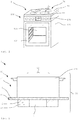
- the FIG. 1 shows a cooking device 1 according to the invention, which is designed here as part of a cooking appliance 100.
- the cooking appliance 1 or the cooking appliance 100 can be designed both as a built-in appliance and as a self-sufficient cooking appliance 1 or stand-alone cooking appliance 100.
- the cooking device 1 here comprises a hob 11 with four cooking zones 21.
- Each of the cooking zones 21 here has at least one heatable cooking area 31 for cooking food.
- a heating device 2 not shown here, is provided in total for each hotplate 21.
- the heating devices 2 are designed as induction heating sources and each have an induction device 12 for this purpose. But it is also possible that a cooking area 31 is not associated with any particular cooking area 21, but represents any location on the hob 11. In this case, the cooking area 31 may have a plurality of induction devices 12 and in particular a plurality of induction coils and be formed as part of a so-called full-surface induction unit.
- a pot can be placed anywhere on the hob 11, wherein during cooking only the corresponding induction coils are driven in the pot or are active.
- Other types of heaters 2 are also possible, such as gas, infrared or somehowsshreddedettin.
- the cooking device 1 can be operated here via the operating devices 105 of the cooking appliance 100.
- the cooking device 1 can also be designed as a self-sufficient cooking device 1 with its own operating and control device. Also possible is an operation via a touch-sensitive surface or a touch screen or remotely via a computer, a smartphone or the like.
- the cooking appliance 100 is here designed as a stove with a cooking chamber 103, which can be closed by a cooking chamber door 104.
- the cooking chamber 104 can be heated by various heating sources, such as a Um Kunststoffsagenmaschine.
- Other heating sources such as a top heat radiator and a bottom heat radiator and a microwave heat source or a vapor source and the like may be provided.
- the sensor device 3 can detect a variable, via which the temperature of a pot can be determined, which is turned off in the cooking area 31.
- each cooking area 31 and / or each cooking place 21 can be assigned a sensor device 3.
- the sensor device 3 is operatively connected to a control device 106 here.
- the control device 106 is designed to control the heating devices 2 as a function of the parameters detected by the sensor device 3.
- the cooking device 1 is preferably designed for an automatic cooking operation and has various automatic functions.
- a soup can be boiled briefly and then kept warm, without a user having to supervise the cooking process or set a heating level.
- he sets the pot with the soup on a hob 21 and selects the corresponding automatic function via the operating device 105, here z.
- the operating device 105 here z.
- the temperature of the pot bottom is determined during the cooking process.
- the control device 106 sets the heating power of the heating device 2 accordingly.
- the temperature of the bottom of the pot is monitored continuously, so that when the desired temperature or when boiling the soup, the heating power is regulated down.
- the automatic function it is also possible by the automatic function to perform a longer cooking process at one or more different desired temperatures, for. B. to slowly let rice pudding draw.
- a cooking device 1 is shown in a sectional side view very schematic.
- the cooking device 1 here has a carrier device 5 designed as a glass ceramic plate 15.
- the glass ceramic plate 15 may in particular be designed as a ceramic hob or the like or at least comprise such. Also possible are other types of support means 5.
- On the glass ceramic plate 15 is here a cookware or food containers 200, such as a pot or a pan, in which food or food can be cooked.
- a sensor device 3 is provided which detects heat radiation in a detection region 83 here.
- the detection area 83 is provided in the installed position of the cooking device 1 above the sensor device 3 and extends upward through the glass ceramic plate 15 to the food container 200 and beyond, if there is no food container 200 is placed there.
- an induction device 12 for heating the cooking area 31 is attached below the glass ceramic plate 15, an induction device 12 for heating the cooking area 31 is attached.
- the induction device 12 is here annular and has in the middle a recess in which the sensor device 3 is mounted.
- Such an arrangement of the sensor device 3 has the advantage that it is still in the detection range 83 of the sensor device even if the food container 200 is not centered on the cooking point 21.
- the sensor device 3 may also not be arranged centrally in the induction device. If an induction device has, for example, a dual-circuit induction coil, then at least one sensor device 3 can be arranged in a space provided between the two induction coils of the induction device.
- the FIG. 3 shows a schematic cooking device 1 in a sectional side view.
- the cooking device 1 has a glass ceramic plate 15, below which the induction device 12 and the sensor device 3 are mounted.
- the sensor device 3 has a first sensor unit 13 and another sensor unit 23. Both sensor units 13, 23 are suitable for non-contact detection of thermal radiation and designed as a thermopile or thermopile.
- the sensor units 13, 23 are each equipped with a filter device 43, 53 and provided for detecting heat radiation emanating from the cooking area 31.
- the thermal radiation emanates, for example, from the bottom of a food container 200, penetrates the glass ceramic plate 15 and reaches the sensor units 13, 23.
- the sensor device 3 is advantageously mounted directly underneath the glass ceramic plate 15 in order to maximize the proportion of heat radiation emanating from the cooking region 31 without great losses to be able to capture.
- the sensor units 13, 23 are provided close to the glass ceramic plate 15.
- a magnetic shielding device 4 which consists of a ferrite body 14 here.
- the ferrite body 14 is designed here essentially as a hollow cylinder and surrounds the sensor units 13, 23 in an annular manner Shielding device 4 shields the sensor device 3 against electromagnetic interactions and in particular against the electromagnetic field of the induction device 12 from. Without such shielding, the magnetic field generated by induction device 12 during operation could undesirably heat parts of sensor device 3 as well, resulting in unreliable temperature sensing and inferior measurement accuracy.
- the magnetic shielding device 4 thus considerably improves the accuracy and reproducibility of the temperature detection.
- the magnetic shielding device 4 may also consist at least in part of at least one at least partially magnetic material and an at least partially electrically non-conductive material.
- the magnetic material and the electrically non-conductive material may be arranged alternately and in layers. Also possible are other materials or materials which have at least partially magnetic properties and also have electrically insulating properties or at least low electrical conductivity.
- the sensor device 3 has at least one optical screen device 7, which is provided to shield radiation influences and in particular heat radiation, which act on the sensor units 13, 23 from outside the detection zone 83.
- the optical shield device 7 is designed here as a tube or a cylinder 17, wherein the cylinder 17 is hollow and the sensor units 13, 23 surrounds approximately annular.
- the cylinder 17 is made of stainless steel here. This has the advantage that the cylinder 17 has a reflective surface which reflects a large proportion of the much heat radiation or absorbs as little heat radiation as possible. The high reflectivity of the surface on the outside of the cylinder 17 is particularly advantageous for the shielding against thermal radiation.
- the high reflectivity of the surface on the inside of the cylinder 17 is also advantageous in order to direct thermal radiation from (and in particular only out) the detection area 83 to the sensor units 13, 23.
- the optical screen device 7 can also be configured as a wall, which surrounds the sensor device 13, 23 at least partially and preferably annularly.
- the cross section may be round, polygonal, oval or rounded. Also possible is a configuration as a cone.
- an insulation device 8 for thermal insulation is provided, which is arranged between the optical shield device 7 and the magnetic shielding device 4.
- the insulation device 8 consists here of an air layer 18, which is between the ferrite 14 and the cylinder 17.
- the insulation device 8 in particular a heat conduction from the ferrite 14 to the cylinder 17 is counteracted.
- the insulation device 8 has, in particular, a thickness of between approximately 0.5 mm and 5 mm and preferably a thickness of 0.8 mm to 2 mm and particularly preferably a thickness of approximately 1 mm.
- the isolation device 8 may also be at least one medium with a correspondingly low heat conduction, such. B. include a foam material and / or a polystyrene plastic or other suitable insulating material.
- the sensor units 13, 23 are arranged here in a thermally conductive manner on a thermal compensation device 9 and in particular are coupled in a thermally conductive manner to the thermal compensation device 9.
- the thermal compensation device 9 has for this purpose two coupling devices 29, which are formed here as depressions, in which the sensor units 13, 23 are embedded accurately. This ensures that the sensor units 13, 23 are at a common and relatively constant temperature level.
- the thermal compensation device 9 ensures a homogeneous temperature of the sensor unit 13, 23, when it heats up during operation of the cooking device 1. An unequal own temperature can lead to artefacts during the detection, in particular in the case of sensor units 13, 23 designed as thermopiles.
- a spacing between cylinder 17 and thermal compensation device 9 is provided.
- the copper plate 19 may also be provided as the bottom 27 of the cylinder 17.
- the thermal compensation device 9 is designed here as a solid copper plate 19.
- the thermal compensation device 9 is also possible at least in part another material with a correspondingly high heat capacity and / or a high thermal conductivity.
- the sensor device 3 here has a radiation source 63, which can be used to determine the reflection properties of the measuring system or the emissivity of a food container 200.
- the radiation source 63 is embodied here as a lamp 111, which emits a signal in the wavelength range of the infrared light and the visible light.
- the radiation source 63 may also be formed as a diode or the like.
- the lamp 111 is used here in addition to the reflection determination for signaling the operating state of the cooking device 1.
- a region of the thermal compensation device 9 or the copper plate 19 is formed as a reflector 39.
- the copper plate 19 has a concave-shaped depression, in which the lamp 111 is arranged.
- the copper plate 19 is also coated with a gold-containing coating to increase the reflectivity.
- the gold-containing layer has the advantage that it also protects the thermal compensation device 9 from corrosion.
- the thermal compensation device 9 is attached to a holding device 10 designed as a plastic holder.
- the holding device 10 has a connecting device 20, not shown here, by means of which the holding device 10 can be latched to a support means 30.
- the support device 30 is formed here as a printed circuit board 50. On the support means 30 and the circuit board 50 also other components may be provided, such. B electronic components, control and computing devices and / or mounting or mounting elements.
- a sealing device 6 is provided between the glass ceramic plate 15 and the induction device 12, which is designed here as a micanite layer 16.
- the micanite layer 16 is used for thermal insulation, so that the induction device 12 is not heated by the heat of the cooking area 31.
- a micanite layer 16 for thermal insulation between the ferrite body 14 and the glass-ceramic plate 15 is provided here. This has the advantage that the heat transfer from the hot in the glass ceramic plate 15 to the ferrite 14 is severely limited. As a result, hardly any heat emanates from the ferrite body 14, which could be transmitted to the insulation device 8 or the optical screen device. The micanite layer 16 thus counteracts an undesirable heat transfer to the sensor device 3, which increases the reliability of the measurements.
- the microlayer 16 seals the sensor device 3 dust-tight against the remaining regions of the cooking device 1.
- the micanite layer 16 has a thickness between about 0.2 mm and 4 mm, preferably from 0.2 mm to 1.5 mm and particularly preferably a thickness of 0.3 mm to 0.8 mm.
- the cooking device 1 has on the underside a cover 41, which is designed here as an aluminum plate and covers the Indu Vietnameseseicardi 12.
- the covering device 41 is connected to a housing 60 of the sensor device 3 via a screw connection 122.
- the sensor device 3 is arranged elastically relative to the glass ceramic plate 15.
- a damping device 102 is provided which has a spring device 112 here.
- the spring device 112 is connected at a lower end to the inside of the housing 60 and at an upper end to the printed circuit board 50.
- the spring device 112 presses the printed circuit board 50 with the ferrite body 14 and the micanite layer 16 mounted thereon upwards against the glass-ceramic plate 15.
- Such an elastic arrangement is particularly advantageous since the sensor device 3 should be arranged as close as possible to the glass ceramic plate 15 for metrological reasons. This directly adjacent arrangement of the sensor device 3 on the glass ceramic plate 15 could cause damage to the glass ceramic plate 15 in the event of impacts or impacts. Due to the elastic reception of the sensor device 3 relative to the carrier device 5, shocks or impacts are damped on the glass ceramic plate 15 and thus reliably prevent such damage.
- the first sensor unit 13 detects heat radiation emanating from the bottom of the pot as mixed radiation together with the heat radiation which is emitted by the glass-ceramic plate 15.
- the portion of the radiation output emanating from the glass ceramic plate 15 is calculated out of the mixed radiation power.
- the other sensor unit 23 is provided to detect only the heat radiation of the glass-ceramic plate 15.
- the other sensor unit 23 has a filter device 53, which transmits essentially only radiation having a wavelength greater than 5 ⁇ m to the sensor unit 23. The reason for this is that radiation with a wavelength greater than 5 microns is not or hardly transmitted by the glass ceramic plate 15.
- the other sensor unit 23 thus essentially detects the heat radiation emitted by the glass ceramic plate 15. With the knowledge of the portion of the heat radiation, which is emitted from the glass ceramic plate 15, can be determined in per se known, the proportion of heat radiation, which emanates from the bottom of the pot.
- the first sensor unit 13 is equipped with a filter device 43 which is very permeable to radiation in this wavelength range, while the filter device 43 substantially reflects radiation from other wavelength ranges.
- the filter devices 43, 53 are here each formed as an interference filter 433 and in particular designed as a bandpass filter or as a long-pass filter.
- a detection of the radiation in the wavelength range between 3 .mu.m and 5 .mu.m and in particular in the range of 3.1 .mu.m to 4.2 .mu.m be provided, wherein the each sensor unit and filter device is then respectively formed or adapted accordingly.
- the determination of a temperature from a specific radiant power is a known method.
- the decisive factor is that the emissivity of the body is known, from which the temperature is to be determined. In the present case, therefore, the emissivity of the pot bottom must be known or determined for a reliable temperature determination.
- the sensor device 3 here has the advantage that it is designed to determine the emissivity of a Gargut variousers 200. This is particularly advantageous, since thus any cookware can be used and not just a specific food container whose emissivity must be known in advance.
- the lamp 111 emits a signal, in particular a light signal, which has a proportion of heat radiation in the wavelength range of the infrared light.
- the radiant power or thermal radiation of the lamp 111 passes through the glass ceramic plate 15 on the bottom of the pot and is partially reflected there and partially absorbed.
- the radiation reflected from the bottom of the pot passes through the glass-ceramic plate 15 back to the sensor device 3, where it is detected by the first sensor unit 13.
- the own thermal radiation of the pot bottom and the thermal radiation of the glass ceramic plate 15 reach the first sensor unit 13.
- the lamp 111 is switched off and only the heat radiation of the pot bottom and the glass ceramic plate 15 is detected .
- the proportion of the reflected signal radiation, from which the emissivity of the pot bottom can be determined, then arises in principle as a difference from the previously detected total radiation with the lamp 111 switched on minus the heat radiation of the pot bottom and the glass ceramic plate with the lamp 111 switched off.
- At least one reference value with regard to reflected radiation and the associated emissivity is deposited in a memory unit which cooperates with the sensor device and is not shown in the figures, wherein the memory unit can be arranged, for example, on the printed circuit board 50.
- the respective actual emissivity of the pot bottom can then be determined based on a comparison of the reflected signal radiation with the at least one reference value.
- the proportion of the signal radiation absorbed by the bottom of the pot is determined. This results according to methods known per se from the radiation power emitted by the lamp 111 less the signal radiation reflected from the bottom of the pot.
- the radiation power of the lamp 111 is either fixed and thus known or is, for example, by a measurement with the other sensor unit 23rd certainly.
- the other sensor unit 23 detects a wavelength range of the signal radiation, which is almost completely reflected by the glass ceramic plate 15.
- the emitted radiation power can be determined in a very suitable approximation, whereby inter alia a wavelength dependence of the radiation line or the spectrum of the lamp 111 must be taken into account.
- the degree of absorption of the pot bottom can be determined in a known manner. Since the absorption capacity of a body corresponds in principle to the emissivity of a body, the desired emissivity can be derived from the degree of absorption of the pot bottom. With the knowledge of the emissivity and the amount of thermal radiation, which emanates from the bottom of the pot, the temperature of the pot bottom can be determined very reliably.
- the emissivity is preferably continuously redefined in the shortest possible intervals. This has the advantage that a subsequent change in the emissivity does not lead to a falsified measurement result.
- a change in the emissivity may occur, for example, when the cookware bottom has different emissivities and is displaced on the cooking surface 21. Different emissivities are very common in cookware trays observed because z. B. already light soiling, corrosion or even different coatings or coatings can have a major impact on the emissivity.
- the lamp 111 is also used here for signaling the operating state of the cooking device 1 in addition to the determination of the emissivity or the determination of the reflection behavior of the measuring system.
- the signal of the lamp 111 also includes visible light, which is perceptible by the glass-ceramic plate 15.
- the lamp 111 indicates to a user that an automatic function is in operation.
- Such an automatic function can, for. B. be a cooking operation, in which the heater 2 is controlled automatically in dependence of the determined pot temperature. This is particularly advantageous because the lighting up of the lamp 111 does not confuse the user. The user knows from experience that the lighting is an operation indicator and belongs to the normal appearance of the cooking device 1.
- a flash of the lamp 111 is not a malfunction and the cooking device 1 may not work properly.
- the lamp 111 may also light up in a certain duration and at certain intervals. It is possible z. B. also that different operating states can be output via different flashing frequencies. Different signals are also possible via different on / off sequences.
- a sensor device 3 with a radiation source 63 which is suitable for displaying at least one operating state, is provided for each cooking point 21 or each (possible) cooking region 31.
- At least one arithmetic unit may be provided for the necessary calculations for determining the temperature and for the evaluation of the detected variables.
- the arithmetic unit can be at least partially provided on the circuit board 50.
- the control device 106 it is also possible, for example, for the control device 106 to be designed accordingly, or at least one separate arithmetic unit is provided.
- the FIG. 4 shows a development in which below the glass ceramic plate 15, a security sensor 73 is attached.
- the safety sensor 73 is designed here as a temperature-sensitive resistor, such as a thermistor, in particular an NTC sensor, and thermally conductively connected to the glass ceramic plate 15.
- the safety sensor 73 is provided here to be able to detect a temperature of the cooking area 31 and in particular of the glass ceramic plate 15. If the temperature exceeds a certain value, there is a risk of overheating and the heaters 2 are switched off.
- the safety sensor 73 is operatively connected to a safety device, not shown here, which can trigger a safety state depending on the detected temperature.
- a security condition has z. B. the shutdown of the heaters 2 and the cooking device 1 result.
- the safety sensor 73 is assigned here as a further sensor unit 33 of the sensor device 3.
- the values detected by the safety sensor 73 are also taken into account for the determination of the temperature by the sensor device 3.
- the values of the safety sensor 73 are used. So z. B. the temperature, which was determined by means of the other sensor unit 23 on the detected thermal radiation, are compared with the temperature detected by the safety sensor 73. This adjustment can on the one hand serve to control the function of the sensor device 3, but on the other hand can also be used for a tuning or adjustment of the sensor device 3.
- a sensor device 3 is likewise shown, in which a safety sensor 73 is assigned as a further sensor unit 33 to the sensor device 3. Unlike the one in the FIG. 4 described embodiment, but no other sensor unit 23 is provided here. The task of the other sensor unit 23 is taken over here by the safety sensor 73.
- the safety sensor 73 is used to determine the temperature of the glass ceramic plate 15. For example, with knowledge of this temperature from the thermal radiation, which detects the first sensor unit 13, the proportion of a pot bottom can be determined.
- the other sensor unit 23 may be referred to as a second sensor unit.
- the further sensor unit 33 may be referred to as a third sensor unit. In the embodiment according to Fig. 5 only the first sensor unit and the third sensor unit are provided.
- FIG. 6 Another embodiment of a cooking device 1 is in the FIG. 6 shown.
- a common sealing device 6 for the induction device 12 and the ferrite body 14 of the sensor device 3 is provided.
- the sealing device 6 is designed as a micanite layer 16 which has a recess in the detection area 83 of the sensor device 3.
- the FIG. 7 shows a schematic, magnetic shielding 4, which is formed as a hollow, cylindrical ferrite body 14.
- a schematic, magnetic shielding 4 which is formed as a hollow, cylindrical ferrite body 14.
- the wall of the ferrite body 14 has a thickness of about 1 mm to 10 mm and in particular from 2 mm to 5 mm, and particularly preferably from 2.5 mm to 4 mm and in particular of 3 mm or more.
- FIG. 8 is an optical shield device 7 shown schematically, which is designed here as a cylinder 17.
- the cylinder has here three locking devices 80, which are suitable for connection to a holding device 10.
- a thermal compensation device 9 is in the FIG. 9 shown.
- the thermal compensation device 9 is designed as a copper plate 19.
- the copper plate has a thickness of 0.5 mm to 4 mm or even 10 mm or more, and more preferably from 0.8 mm to 2 mm, and more preferably 1 mm or more.
- the copper plate 19 here has two coupling devices 29.
- the coupling device 29 is suitable and provided to receive a sensor unit 13, 23 thermally conductive.
- the copper plate 19 has a reflector device 39, which can reflect the radiation of a radiation source 63 and, in particular, can focus.
- FIG. 10 shows a holding device 10, which is designed as a plastic holder.
- the holding device 10 preferably has a thickness between 0.3 mm and 3 mm or even 6 mm, and particularly preferably a thickness of 1 mm or more.
- the holding device 10 includes, for example, three connecting devices, of which only two connecting devices 20 are visible in the figure, by means of which the holding device 10 z. B. is connectable to a support device 30.
- the holding device 10 on three receiving devices 40, which are formed here as webs.
- the recording devices 40 are suitable for receiving the optical screen device 7 and arranging it at a defined distance from the magnetic shielding device 4. To carry out contacts receiving openings 70 are provided.
- the holding device 10 may also have further, not shown receptacles 40 which z. B.
- Such receiving devices 40 are in particular for the defined arrangement of a magnetic Shielding device 4, an optical shield device 7, a thermal compensation device 9, an insulation device 8 and / or a support device 30 is provided.
- a sensor unit 13 for non-contact detection of heat radiation is listed.
- the sensor unit 13 is designed as a thermopile or thermopile.
- the sensor unit 13 has contacts in order to connect them, for example, to a printed circuit board 50 or board.
- a filter device 43 is arranged here.
- FIG. 12a shows a formed as a thermopile sensor unit 13 with a filter device 43 in a sectioned, schematic side view.
- the filter device 43 is arranged here on the region in which the thermal radiation impinges on the sensor unit 13 and is detected.
- the filter device 43 is here attached to the sensor unit 13 with an adhesive connection means 430 in a thermally conductive manner.
- the connecting means 430 here is an adhesive with a thermal conductivity of at least 1 W m -1 K -1 (W / (mK)) and preferably of 0.5 W m -1 K -1 (W / (mK)). Also possible and preferred is a thermal conductivity of more than 4 W m -1 K -1 (W / (mK)).
- heat can be dissipated from the filter device 43 to the sensor unit 43.
- the dissipation of the heat prevents the sensor unit 13 from detecting the self-heat of the filter device 43, which would lead to a falsified measurement result.
- the heat from the filter device 43 via the sensor unit 13 can also be forwarded to the thermal compensation device 9 or the copper plate 19.
- Such indirect dissipation of the heat from the filter device 43 via the sensor unit 13 to the copper plate 19 is also particularly favorable since the copper plate 19 has a high heat capacity.
- the adhesive may be, for example, a thermosetting, one-component, solvent-free silver-filled epoxy conductive adhesive. Due to the proportion of silver or silver-containing compounds a very favorable thermal conductivity is achieved. Also possible is a proportion of other metals or metal compounds with a corresponding thermal conductivity. Such an adhesive ensures a thermally conductive connection, which is durable and stable even at the temperatures to be expected in a cooking device 1.
- the filter device 43 is designed as an interference filter 433 and here has four filter layers 432 with a different refractive index and with dielectric properties. In this case, filter layers 432 with higher and lower refractive indices are alternately stacked and connected.
- the filter layers 432 are, in particular, very thin, preferably a few nanometers to 25 nm.
- the carrier layer for the filter layers 432 here is a filter base 431 made of a silicon-containing material with a thickness of more than 0.2 mm.
- the filter device 43 is designed for this purpose and capable of transmitting a wavelength range in the infrared spectrum and substantially reflecting radiation outside this range.
- FIG. 12b shows a further embodiment of a sensor unit 13 with a filter device 43, wherein the filter device 43 is glued here only partially on the sensor device 13.
- the region in which the heat radiation strikes and is detected on the sensor unit 13 is surrounded here by a raised edge region.
- the connecting means 430 was applied only in an edge region. This has the advantage that the heat radiation to be detected does not have to pass through the connection means 430 before it strikes the sensor unit 13.
- a sensor device 3 is shown in a plan view. For clarity and distinctiveness, some parts or areas are shaded. It can be clearly seen that the sensor device 3 has a concentric structure according to the onion shell principle. Inside there is a thermal compensation device 9 or a copper plate 19, on which two sensor units 13, 23 and designed as a lamp 111 radiation source 63 are arranged. So that no unwanted heat radiation from the side of the sensor units 13, 23 is incident, the sensor units 13, 23 are surrounded by an optical screen device 7 and a cylinder 17. The cylinder 17 is spaced from the copper plate 19, so that as possible no heat transfer between the cylinder 17 and copper plate 19 can take place. The cylinder 17 is surrounded by a magnetic shielding device 4 and a ferrite body 14, respectively. The ferrite body 14 represents the outermost layer of the sensor device 3 and shields it against electromagnetic interactions.
- the sensor device 3 is preferably provided as close as possible below a carrier device 5, a sealing device 6 or a micanite layer 16 lies on the ferrite body 14, which considerably reduces a heat transfer from the carrier device 5 to the ferrite body 14.
- an insulation device 8 is formed between the ferrite body 14 and the cylinder 17, an insulation device 8 is formed.
- the insulation device 8 is here an air layer 18.
- the air layer 18 counteracts a heat transfer from the ferrite body 14 to the cylinder 17.
- the sensor units 13, 23 in the interior of the sensor device 3 are thus very effective against interference, such.
- B. a magnetic field of an induction device 12, heat radiation from outside the detection range 83 and heating by heat conduction, protected.
- Such a configured, shell-like arrangement of the listed components significantly increases the reliability of the measurements performed with the sensor device 3.
- FIG. 14 shows a sensor device 3 in an exploded view.
- the items are here shown spatially separated from each other, whereby the arrangement of the items within the sensor device 3 is clearly visible. Also the concentric or onion-peel-like Construction is easy to recognize here. In addition to an improved measurement accuracy, such a structure also allows a particularly production-friendly and cost-effective installation of the sensor device 3.
- a sensor unit 13, 23 may already be adhesively bonded to a filter device 43, 53 in a thermally conductive manner.
- the circuit board 50 may already be partially equipped with electronic components prior to assembly. Preferably z. B. the radiation source 63 already contacted with the circuit board 50.
- the holding device 10 designed as a plastic holder is first mounted on the supporting device 30 designed as a printed circuit board 50.
- the holding device 10 at least one connecting device 20, not shown here, which is connected to the circuit board 50 and z. B. can be locked.
- a holding device 10 with three connecting devices 20 is in the FIG. 10 shown.
- the provided here as a copper plate 19 thermal compensation device 9 is inserted into the holding device 10.
- the sensor units 13, 23 designed as thermopiles or thermopiles are then passed through receiving openings 70 in the copper plate 19, the holding device 10 and the printed circuit board 50.
- the mounting of the holding device 10, the copper plate 19 and the sensor units 13, 23 can also be performed in any other order. So z. B. first inserted the copper plate 19 in the holding device 10, then the sensor units 13, 23 inserted and subsequently the holding device 10 is locked to the circuit board 50. The contacting of the sensor units 13, 23 with the printed circuit board 50 can be done at any time during assembly.
- the contacting of the radiation source 63 designed as a lamp 111 with the printed circuit board 50 can likewise take place at any desired time of assembly. It is preferred to contact the lamp 111 first with the printed circuit board 50 and then to start with the mounting option described above.
- the optical screen device 7 designed as a cylinder 17.
- the cylinder 17 has three latching devices 80, which are latched to the three receiving devices 40 of the holding device 10.
- the holding device 10 preferably has a further, not shown here receiving device 40, which may be formed as a recess, survey, web and / or annular groove or the like.
- the sealing device 6 designed as micanite layer 16 is fastened to the magnetic shielding device 4.
- Other suitable mounting sequences for the cylinder 17, the ferrite body 14 and the sealing device 6 may be provided.
Landscapes
- Engineering & Computer Science (AREA)
- Chemical & Material Sciences (AREA)
- Combustion & Propulsion (AREA)
- Mechanical Engineering (AREA)
- General Engineering & Computer Science (AREA)
- Ceramic Engineering (AREA)
- Physics & Mathematics (AREA)
- Electromagnetism (AREA)
- Induction Heating Cooking Devices (AREA)
- Electric Stoves And Ranges (AREA)
- Radiation Pyrometers (AREA)
Claims (14)
- Dispositif de cuisson (1) comprenant au moins une table de cuisson (11) présentant au moins un point de cuisson (12) et au moins un dispositif chauffant (2) prévu pour chauffer au moins une zone de cuisson (31) et au moins un dispositif de sécurité (107), auquel est associée au moins une unité de détection de sécurité (73), l'unité de détection de sécurité (73) étant conçue pour détecter au moins une variable caractéristique pour les températures, et présentant au moins un dispositif de commande (106) et au moins un dispositif de détection (3), le dispositif de détection (3) étant prévu pour détecter au moins une variable caractéristique pour les températures de la zone de cuisson (31), et le dispositif de commande (106) étant conçu et approprié, au moins partiellement, pour commander le dispositif chauffant (2) en fonction de la variable détectée par le dispositif de détection (3), au moins une première unité de détection (13) et au moins une autre unité de détection (33) étant associées au dispositif de détection (3), une première unité de détection (13) étant conçue et appropriée pour détecter sans contact le rayonnement thermique et l'unité de détection de sécurité (73) étant associée au dispositif de détection (3) en tant qu'autre unité de détection (33), caractérisé en ce que le dispositif de détection (3) comporte au moins un dispositif de filtration (43, 53) et, en outre, une autre unité de détection (23), le dispositif de filtration (43, 53) étant conçu et approprié pour réfléchir et/ou pour transmettre le rayonnement électromagnétique en fonction de la longueur d'onde et/ou de la polarisation et/ou de l'angle d'incidence, la première unité de détection (13) et l'autre unité de détection (23) étant appropriées pour détecter sans contact le rayonnement thermique et conçues sous forme de thermopile, et les unités de détection (13, 23) étant équipées chacune d'un dispositif de filtration (43, 53) et prévues pour détecter le rayonnement thermique émis par la zone de cuisson (31), les dispositifs de filtration (43, 53) agissant différemment sur les unités de détection optique (13, 23), le dispositif de filtration (43) étant conçu comme un filtre d'interférence (433) et comprenant quatre couches de filtration (432) qui présentent un indice de réfraction et des propriétés diélectriques différents, les couches de filtration (432) à indice de réfraction supérieur et inférieur étant empilées en alternance, les couches de filtration (432) étant reliées, et les couches de filtration (432) étant très minces, celles-ci présentant une épaisseur allant de quelques nanomètres à 25 nm, le dispositif de filtration (43) comportant une couche de support servant de base de filtration (431) pour les couches de filtration (432), la base de filtration (431) étant constituée d'un matériau contenant du silicium d'une épaisseur supérieure à 0,2 mm, et le dispositif de filtration (43) étant conçu et approprié pour transmettre une plage de longueurs d'ondes dans le spectre infrarouge et pour refléter sensiblement le rayonnement en dehors de cette plage.
- Dispositif de cuisson (1) selon la revendication 1, caractérisé en ce que la table de cuisson présente au moins un dispositif de support (5) qui est approprié et conçu pour le positionnement d'au moins un récipient de produit à cuire, et en ce que le dispositif de détection (3), dans la position de montage de la table de cuisson (11), est disposé au moins partiellement en-dessous du dispositif de support (5).
- Dispositif de cuisson (1) selon l'une des revendications précédentes, caractérisé en ce que l'autre unité de détection (33) détecte une température au niveau de la face inférieure du dispositif de support (5) et est disposée de façon thermiquement conductrice au niveau de la face inférieure du dispositif de support (5).
- Dispositif de cuisson (1) selon l'une des revendications précédentes, caractérisé en ce que l'autre unité de détection (33) comprend une thermistance ou est conçue en tant que telle.
- Dispositif de cuisson (1) selon l'une des revendications précédentes, caractérisé en ce qu'au moins une autre unité de détection (23) est prévue, laquelle est conçue et appropriée pour détecter sans contact le rayonnement thermique.
- Dispositif de cuisson (1) selon l'une des revendications précédentes, caractérisé en ce qu'au moins une unité de détection (13, 23, 33) est appropriée et conçue pour contrôler au moins une unité de détection (13, 23, 33).
- Dispositif de cuisson (1) selon l'une des revendications précédentes, caractérisé en ce qu'au moins une unité de détection (13, 23, 33) est appropriée et conçue pour déclencher un état de sécurité.
- Dispositif de cuisson (1) selon l'une des revendications précédentes, caractérisé en ce qu'au moins un dispositif d'induction (12) est prévu pour le dispositif chauffant (2) et en ce que le dispositif de détection (3) comprend au moins un dispositif de blindage magnétique (4), le dispositif de blindage magnétique (4) étant conçu et approprié pour assurer un blindage contre les interactions électromagnétiques et en particulier pour assurer un blindage contre le champ électromagnétique du dispositif d'induction (12).
- Dispositif de cuisson (1) selon l'une des deux revendications précédentes, caractérisé en ce qu'au moins un dispositif d'étanchéité (6) est prévu pour assurer l'isolation thermique, au moins une partie du dispositif d'étanchéité (6) étant disposée au moins partiellement entre le dispositif de support (5) et au moins une partie du dispositif de détection (3) et/ou du dispositif de blindage magnétique (4).
- Dispositif de cuisson (1) selon l'une des trois revendications précédentes, caractérisé en ce que le dispositif de détection (3) présente au moins un dispositif de protection optique (7), le dispositif de protection optique (7) étant disposé en étant entouré au moins partiellement par le dispositif de blindage magnétique (4).
- Dispositif de cuisson (1) selon la revendication précédente, caractérisé en ce que le dispositif de détection (3) comprend au moins un dispositif d'équilibrage thermique (9), le dispositif d'équilibrage thermique (9) présentant au moins un dispositif de couplage (29) qui est approprié et conçu pour raccorder au moins partiellement de façon thermiquement conductrice au moins une unité de détection (13, 23) au dispositif d'équilibrage thermique (9).
- Dispositif de cuisson (1) selon l'une des revendications précédentes, caractérisé en ce que le dispositif de détection (3) présente au moins une source de rayonnement (63) qui émet un signal, en particulier dans la plage de longueurs d'ondes de la lumière infrarouge et/ou de la lumière visible.
- Dispositif de cuisson (1) selon l'une des revendications précédentes, caractérisé en ce que le dispositif de détection (3) présente au moins un moyen de retenue (10),
au moins deux unités pouvant, par le moyen de retenue (10), être logées dans un agencement défini, et les unités étant prises dans un groupe d'unités comprenant une unité de détection (13, 23) et/ou le dispositif de blindage magnétique (4) et/ou le dispositif de protection optique (7) et/ou un dispositif d'isolation (8) et/ou la source de rayonnement (63) et/ou le dispositif d'équilibrage thermique (9). - Dispositif de cuisson (1) selon l'une des revendications précédentes, caractérisé en ce que le dispositif de filtration (43) est fixé avec un moyen de liaison adhésif (430) de manière thermiquement conductrice sur l'unité de détection (13), et en ce que le moyen de liaison (430) est un adhésif présentant une conductivité thermique d'au moins 0,5 W m-1 K-1, la chaleur étant transmise du dispositif de filtration (43) au dispositif d'équilibrage thermique (9) par l'intermédiaire de l'unité de détection (13).
Priority Applications (1)
| Application Number | Priority Date | Filing Date | Title |
|---|---|---|---|
| EP19155518.4A EP3515154B1 (fr) | 2013-03-04 | 2014-02-03 | Dispositif de cuisson |
Applications Claiming Priority (1)
| Application Number | Priority Date | Filing Date | Title |
|---|---|---|---|
| DE102013102119.0A DE102013102119A1 (de) | 2013-03-04 | 2013-03-04 | Kocheinrichtung |
Related Child Applications (2)
| Application Number | Title | Priority Date | Filing Date |
|---|---|---|---|
| EP19155518.4A Division-Into EP3515154B1 (fr) | 2013-03-04 | 2014-02-03 | Dispositif de cuisson |
| EP19155518.4A Division EP3515154B1 (fr) | 2013-03-04 | 2014-02-03 | Dispositif de cuisson |
Publications (2)
| Publication Number | Publication Date |
|---|---|
| EP2775792A1 EP2775792A1 (fr) | 2014-09-10 |
| EP2775792B1 true EP2775792B1 (fr) | 2019-07-10 |
Family
ID=50071563
Family Applications (2)
| Application Number | Title | Priority Date | Filing Date |
|---|---|---|---|
| EP19155518.4A Active EP3515154B1 (fr) | 2013-03-04 | 2014-02-03 | Dispositif de cuisson |
| EP14401016.2A Active EP2775792B1 (fr) | 2013-03-04 | 2014-02-03 | Appareil de cuisson |
Family Applications Before (1)
| Application Number | Title | Priority Date | Filing Date |
|---|---|---|---|
| EP19155518.4A Active EP3515154B1 (fr) | 2013-03-04 | 2014-02-03 | Dispositif de cuisson |
Country Status (3)
| Country | Link |
|---|---|
| EP (2) | EP3515154B1 (fr) |
| DE (1) | DE102013102119A1 (fr) |
| ES (1) | ES2813082T3 (fr) |
Cited By (1)
| Publication number | Priority date | Publication date | Assignee | Title |
|---|---|---|---|---|
| EP4395458A1 (fr) * | 2022-12-27 | 2024-07-03 | Arçelik Anonim Sirketi | Cuiseur à chauffage par induction |
Families Citing this family (2)
| Publication number | Priority date | Publication date | Assignee | Title |
|---|---|---|---|---|
| DE102013108646A1 (de) | 2013-08-09 | 2015-02-12 | Miele & Cie. Kg | Kocheinrichtung und Verfahren zum Betreiben einer Kocheinrichtung |
| DE102016120667A1 (de) * | 2016-10-28 | 2018-05-03 | Hans Heidolph GmbH | Laborgerät, insbesondere Magnetrührer |
Citations (1)
| Publication number | Priority date | Publication date | Assignee | Title |
|---|---|---|---|---|
| EP1865754A2 (fr) * | 2006-06-09 | 2007-12-12 | BSH Bosch und Siemens Hausgeräte GmbH | Table de cuisson à induction et procédé de calcul d'une température d'un sol d'un récipient de préparation |
Family Cites Families (14)
| Publication number | Priority date | Publication date | Assignee | Title |
|---|---|---|---|---|
| JP2004063451A (ja) * | 2002-06-07 | 2004-02-26 | Ishizuka Electronics Corp | 誘導加熱調理器の放射温度検知装置および該装置用演算装置 |
| JP2004227976A (ja) * | 2003-01-24 | 2004-08-12 | Matsushita Electric Ind Co Ltd | 誘導加熱調理器 |
| JP4617676B2 (ja) * | 2004-01-27 | 2011-01-26 | パナソニック株式会社 | 誘導加熱調理器 |
| JP4892872B2 (ja) * | 2005-05-27 | 2012-03-07 | パナソニック株式会社 | 誘導加熱調理器 |
| JP4839682B2 (ja) * | 2005-06-08 | 2011-12-21 | パナソニック株式会社 | 誘導加熱調理器 |
| JP4311413B2 (ja) * | 2006-04-17 | 2009-08-12 | パナソニック株式会社 | 誘導加熱装置 |
| JP5066864B2 (ja) * | 2006-08-08 | 2012-11-07 | パナソニック株式会社 | 誘導加熱装置 |
| JP4965648B2 (ja) * | 2007-03-12 | 2012-07-04 | パナソニック株式会社 | 誘導加熱調理器 |
| US8581159B2 (en) | 2007-06-05 | 2013-11-12 | Miele & Cie. Kg | Control method for a cooktop and cooktop for carrying out said method |
| JP5209383B2 (ja) * | 2008-06-13 | 2013-06-12 | 株式会社東芝 | 誘導加熱調理器 |
| JP2009224340A (ja) * | 2009-07-06 | 2009-10-01 | Panasonic Corp | 誘導加熱調理器 |
| ES2378938B1 (es) * | 2009-11-03 | 2013-03-14 | BSH Electrodomésticos España S.A. | Campo de cocción con al menos un sensor de temperatura. |
| JP5506406B2 (ja) * | 2010-01-04 | 2014-05-28 | 三菱電機株式会社 | 誘導加熱調理器 |
| ES2423383B1 (es) * | 2012-02-10 | 2014-09-12 | Bsh Electrodomésticos España, S.A. | Aparato de cocción por inducción con sensor de infrarrojos |
-
2013
- 2013-03-04 DE DE102013102119.0A patent/DE102013102119A1/de not_active Withdrawn
-
2014
- 2014-02-03 ES ES19155518T patent/ES2813082T3/es active Active
- 2014-02-03 EP EP19155518.4A patent/EP3515154B1/fr active Active
- 2014-02-03 EP EP14401016.2A patent/EP2775792B1/fr active Active
Patent Citations (1)
| Publication number | Priority date | Publication date | Assignee | Title |
|---|---|---|---|---|
| EP1865754A2 (fr) * | 2006-06-09 | 2007-12-12 | BSH Bosch und Siemens Hausgeräte GmbH | Table de cuisson à induction et procédé de calcul d'une température d'un sol d'un récipient de préparation |
Cited By (1)
| Publication number | Priority date | Publication date | Assignee | Title |
|---|---|---|---|---|
| EP4395458A1 (fr) * | 2022-12-27 | 2024-07-03 | Arçelik Anonim Sirketi | Cuiseur à chauffage par induction |
Also Published As
| Publication number | Publication date |
|---|---|
| EP2775792A1 (fr) | 2014-09-10 |
| EP3515154A1 (fr) | 2019-07-24 |
| EP3515154B1 (fr) | 2020-08-05 |
| DE102013102119A1 (de) | 2014-09-18 |
| ES2813082T3 (es) | 2021-03-22 |
Similar Documents
| Publication | Publication Date | Title |
|---|---|---|
| EP2153698B1 (fr) | Procédé de commande d'une table de cuisson et table de cuisson pour mettre en oeuvre ce procédé | |
| EP1865754B1 (fr) | Table de cuisson à induction et procédé de calcul d'une température d'un sol d'un récipient de préparation | |
| EP2775792B1 (fr) | Appareil de cuisson | |
| EP1217873B1 (fr) | Procédé et dispositif de détection de la température d'un ustensile de cuisine | |
| WO2015018891A1 (fr) | Dispositif de cuisson et son procédé de fonctionnement | |
| EP2775787B1 (fr) | Appareil de cuisson | |
| EP2775788B1 (fr) | Appareil de cuisson | |
| EP2775790B1 (fr) | Appareil de cuisson | |
| EP2775789B1 (fr) | Dispositif de cuisson et procédé de montage | |
| EP2775784B1 (fr) | Dispositif de cuisson et procédé de fonctionnement | |
| EP3031298A1 (fr) | Dispositif de cuisson et son procédé de fonctionnement | |
| EP2775786B1 (fr) | Appareil de cuisson | |
| EP2775791B1 (fr) | Appareil de cuisson | |
| WO2015018890A1 (fr) | Dispositif de cuisson et son procédé de fonctionnement | |
| EP3031297B1 (fr) | Équipement de cuisson et méthode pour contrôler ledit équipement | |
| DE102013102118A1 (de) | Kocheinrichtung und Verfahren zum Betreiben | |
| DE4422354A1 (de) | Infrarotgesteuerte Garungseinheit | |
| EP3031296B1 (fr) | Equipement de cuisson et methode pour controler le dit equipement | |
| DE102004004022B4 (de) | Kochfeld | |
| DE102019211101A1 (de) | Strahlungsheizeinrichtung und Kochfeld mit einer solchen Strahlungsheizeinrichtung |
Legal Events
| Date | Code | Title | Description |
|---|---|---|---|
| PUAI | Public reference made under article 153(3) epc to a published international application that has entered the european phase |
Free format text: ORIGINAL CODE: 0009012 |
|
| 17P | Request for examination filed |
Effective date: 20140203 |
|
| AK | Designated contracting states |
Kind code of ref document: A1 Designated state(s): AL AT BE BG CH CY CZ DE DK EE ES FI FR GB GR HR HU IE IS IT LI LT LU LV MC MK MT NL NO PL PT RO RS SE SI SK SM TR |
|
| AX | Request for extension of the european patent |
Extension state: BA ME |
|
| R17P | Request for examination filed (corrected) |
Effective date: 20150310 |
|
| RBV | Designated contracting states (corrected) |
Designated state(s): AL AT BE BG CH CY CZ DE DK EE ES FI FR GB GR HR HU IE IS IT LI LT LU LV MC MK MT NL NO PL PT RO RS SE SI SK SM TR |
|
| 17Q | First examination report despatched |
Effective date: 20160628 |
|
| STAA | Information on the status of an ep patent application or granted ep patent |
Free format text: STATUS: EXAMINATION IS IN PROGRESS |
|
| GRAP | Despatch of communication of intention to grant a patent |
Free format text: ORIGINAL CODE: EPIDOSNIGR1 |
|
| STAA | Information on the status of an ep patent application or granted ep patent |
Free format text: STATUS: GRANT OF PATENT IS INTENDED |
|
| INTG | Intention to grant announced |
Effective date: 20190125 |
|
| GRAJ | Information related to disapproval of communication of intention to grant by the applicant or resumption of examination proceedings by the epo deleted |
Free format text: ORIGINAL CODE: EPIDOSDIGR1 |
|
| STAA | Information on the status of an ep patent application or granted ep patent |
Free format text: STATUS: EXAMINATION IS IN PROGRESS |
|
| GRAP | Despatch of communication of intention to grant a patent |
Free format text: ORIGINAL CODE: EPIDOSNIGR1 |
|
| STAA | Information on the status of an ep patent application or granted ep patent |
Free format text: STATUS: GRANT OF PATENT IS INTENDED |
|
| GRAS | Grant fee paid |
Free format text: ORIGINAL CODE: EPIDOSNIGR3 |
|
| GRAA | (expected) grant |
Free format text: ORIGINAL CODE: 0009210 |
|
| STAA | Information on the status of an ep patent application or granted ep patent |
Free format text: STATUS: THE PATENT HAS BEEN GRANTED |
|
| INTC | Intention to grant announced (deleted) | ||
| INTG | Intention to grant announced |
Effective date: 20190523 |
|
| AK | Designated contracting states |
Kind code of ref document: B1 Designated state(s): AL AT BE BG CH CY CZ DE DK EE ES FI FR GB GR HR HU IE IS IT LI LT LU LV MC MK MT NL NO PL PT RO RS SE SI SK SM TR |
|
| REG | Reference to a national code |
Ref country code: GB Ref legal event code: FG4D Free format text: NOT ENGLISH |
|
| REG | Reference to a national code |
Ref country code: CH Ref legal event code: EP Ref country code: AT Ref legal event code: REF Ref document number: 1154934 Country of ref document: AT Kind code of ref document: T Effective date: 20190715 |
|
| REG | Reference to a national code |
Ref country code: DE Ref legal event code: R096 Ref document number: 502014012167 Country of ref document: DE |
|
| REG | Reference to a national code |
Ref country code: IE Ref legal event code: FG4D Free format text: LANGUAGE OF EP DOCUMENT: GERMAN |
|
| REG | Reference to a national code |
Ref country code: NL Ref legal event code: MP Effective date: 20190710 |
|
| REG | Reference to a national code |
Ref country code: LT Ref legal event code: MG4D |
|
| PG25 | Lapsed in a contracting state [announced via postgrant information from national office to epo] |
Ref country code: NO Free format text: LAPSE BECAUSE OF FAILURE TO SUBMIT A TRANSLATION OF THE DESCRIPTION OR TO PAY THE FEE WITHIN THE PRESCRIBED TIME-LIMIT Effective date: 20191010 Ref country code: LT Free format text: LAPSE BECAUSE OF FAILURE TO SUBMIT A TRANSLATION OF THE DESCRIPTION OR TO PAY THE FEE WITHIN THE PRESCRIBED TIME-LIMIT Effective date: 20190710 Ref country code: PT Free format text: LAPSE BECAUSE OF FAILURE TO SUBMIT A TRANSLATION OF THE DESCRIPTION OR TO PAY THE FEE WITHIN THE PRESCRIBED TIME-LIMIT Effective date: 20191111 Ref country code: NL Free format text: LAPSE BECAUSE OF FAILURE TO SUBMIT A TRANSLATION OF THE DESCRIPTION OR TO PAY THE FEE WITHIN THE PRESCRIBED TIME-LIMIT Effective date: 20190710 Ref country code: BG Free format text: LAPSE BECAUSE OF FAILURE TO SUBMIT A TRANSLATION OF THE DESCRIPTION OR TO PAY THE FEE WITHIN THE PRESCRIBED TIME-LIMIT Effective date: 20191010 Ref country code: FI Free format text: LAPSE BECAUSE OF FAILURE TO SUBMIT A TRANSLATION OF THE DESCRIPTION OR TO PAY THE FEE WITHIN THE PRESCRIBED TIME-LIMIT Effective date: 20190710 Ref country code: HR Free format text: LAPSE BECAUSE OF FAILURE TO SUBMIT A TRANSLATION OF THE DESCRIPTION OR TO PAY THE FEE WITHIN THE PRESCRIBED TIME-LIMIT Effective date: 20190710 Ref country code: SE Free format text: LAPSE BECAUSE OF FAILURE TO SUBMIT A TRANSLATION OF THE DESCRIPTION OR TO PAY THE FEE WITHIN THE PRESCRIBED TIME-LIMIT Effective date: 20190710 |
|
| PG25 | Lapsed in a contracting state [announced via postgrant information from national office to epo] |
Ref country code: ES Free format text: LAPSE BECAUSE OF FAILURE TO SUBMIT A TRANSLATION OF THE DESCRIPTION OR TO PAY THE FEE WITHIN THE PRESCRIBED TIME-LIMIT Effective date: 20190710 Ref country code: GR Free format text: LAPSE BECAUSE OF FAILURE TO SUBMIT A TRANSLATION OF THE DESCRIPTION OR TO PAY THE FEE WITHIN THE PRESCRIBED TIME-LIMIT Effective date: 20191011 Ref country code: LV Free format text: LAPSE BECAUSE OF FAILURE TO SUBMIT A TRANSLATION OF THE DESCRIPTION OR TO PAY THE FEE WITHIN THE PRESCRIBED TIME-LIMIT Effective date: 20190710 Ref country code: AL Free format text: LAPSE BECAUSE OF FAILURE TO SUBMIT A TRANSLATION OF THE DESCRIPTION OR TO PAY THE FEE WITHIN THE PRESCRIBED TIME-LIMIT Effective date: 20190710 Ref country code: RS Free format text: LAPSE BECAUSE OF FAILURE TO SUBMIT A TRANSLATION OF THE DESCRIPTION OR TO PAY THE FEE WITHIN THE PRESCRIBED TIME-LIMIT Effective date: 20190710 Ref country code: IS Free format text: LAPSE BECAUSE OF FAILURE TO SUBMIT A TRANSLATION OF THE DESCRIPTION OR TO PAY THE FEE WITHIN THE PRESCRIBED TIME-LIMIT Effective date: 20191110 |
|
| PG25 | Lapsed in a contracting state [announced via postgrant information from national office to epo] |
Ref country code: DK Free format text: LAPSE BECAUSE OF FAILURE TO SUBMIT A TRANSLATION OF THE DESCRIPTION OR TO PAY THE FEE WITHIN THE PRESCRIBED TIME-LIMIT Effective date: 20190710 Ref country code: EE Free format text: LAPSE BECAUSE OF FAILURE TO SUBMIT A TRANSLATION OF THE DESCRIPTION OR TO PAY THE FEE WITHIN THE PRESCRIBED TIME-LIMIT Effective date: 20190710 Ref country code: PL Free format text: LAPSE BECAUSE OF FAILURE TO SUBMIT A TRANSLATION OF THE DESCRIPTION OR TO PAY THE FEE WITHIN THE PRESCRIBED TIME-LIMIT Effective date: 20190710 Ref country code: RO Free format text: LAPSE BECAUSE OF FAILURE TO SUBMIT A TRANSLATION OF THE DESCRIPTION OR TO PAY THE FEE WITHIN THE PRESCRIBED TIME-LIMIT Effective date: 20190710 |
|
| PG25 | Lapsed in a contracting state [announced via postgrant information from national office to epo] |
Ref country code: SK Free format text: LAPSE BECAUSE OF FAILURE TO SUBMIT A TRANSLATION OF THE DESCRIPTION OR TO PAY THE FEE WITHIN THE PRESCRIBED TIME-LIMIT Effective date: 20190710 Ref country code: CZ Free format text: LAPSE BECAUSE OF FAILURE TO SUBMIT A TRANSLATION OF THE DESCRIPTION OR TO PAY THE FEE WITHIN THE PRESCRIBED TIME-LIMIT Effective date: 20190710 Ref country code: IS Free format text: LAPSE BECAUSE OF FAILURE TO SUBMIT A TRANSLATION OF THE DESCRIPTION OR TO PAY THE FEE WITHIN THE PRESCRIBED TIME-LIMIT Effective date: 20200224 Ref country code: SM Free format text: LAPSE BECAUSE OF FAILURE TO SUBMIT A TRANSLATION OF THE DESCRIPTION OR TO PAY THE FEE WITHIN THE PRESCRIBED TIME-LIMIT Effective date: 20190710 |
|
| REG | Reference to a national code |
Ref country code: DE Ref legal event code: R097 Ref document number: 502014012167 Country of ref document: DE |
|
| PLBE | No opposition filed within time limit |
Free format text: ORIGINAL CODE: 0009261 |
|
| STAA | Information on the status of an ep patent application or granted ep patent |
Free format text: STATUS: NO OPPOSITION FILED WITHIN TIME LIMIT |
|
| PG2D | Information on lapse in contracting state deleted |
Ref country code: IS |
|
| 26N | No opposition filed |
Effective date: 20200603 |
|
| PG25 | Lapsed in a contracting state [announced via postgrant information from national office to epo] |
Ref country code: SI Free format text: LAPSE BECAUSE OF FAILURE TO SUBMIT A TRANSLATION OF THE DESCRIPTION OR TO PAY THE FEE WITHIN THE PRESCRIBED TIME-LIMIT Effective date: 20190710 |
|
| REG | Reference to a national code |
Ref country code: CH Ref legal event code: PL |
|
| REG | Reference to a national code |
Ref country code: BE Ref legal event code: MM Effective date: 20200229 |
|
| PG25 | Lapsed in a contracting state [announced via postgrant information from national office to epo] |
Ref country code: MC Free format text: LAPSE BECAUSE OF FAILURE TO SUBMIT A TRANSLATION OF THE DESCRIPTION OR TO PAY THE FEE WITHIN THE PRESCRIBED TIME-LIMIT Effective date: 20190710 Ref country code: LU Free format text: LAPSE BECAUSE OF NON-PAYMENT OF DUE FEES Effective date: 20200203 |
|
| PG25 | Lapsed in a contracting state [announced via postgrant information from national office to epo] |
Ref country code: CH Free format text: LAPSE BECAUSE OF NON-PAYMENT OF DUE FEES Effective date: 20200229 Ref country code: LI Free format text: LAPSE BECAUSE OF NON-PAYMENT OF DUE FEES Effective date: 20200229 |
|
| PG25 | Lapsed in a contracting state [announced via postgrant information from national office to epo] |
Ref country code: IE Free format text: LAPSE BECAUSE OF NON-PAYMENT OF DUE FEES Effective date: 20200203 |
|
| PG25 | Lapsed in a contracting state [announced via postgrant information from national office to epo] |
Ref country code: BE Free format text: LAPSE BECAUSE OF NON-PAYMENT OF DUE FEES Effective date: 20200229 |
|
| REG | Reference to a national code |
Ref country code: AT Ref legal event code: MM01 Ref document number: 1154934 Country of ref document: AT Kind code of ref document: T Effective date: 20200203 |
|
| PG25 | Lapsed in a contracting state [announced via postgrant information from national office to epo] |
Ref country code: AT Free format text: LAPSE BECAUSE OF NON-PAYMENT OF DUE FEES Effective date: 20200203 |
|
| PG25 | Lapsed in a contracting state [announced via postgrant information from national office to epo] |
Ref country code: MT Free format text: LAPSE BECAUSE OF FAILURE TO SUBMIT A TRANSLATION OF THE DESCRIPTION OR TO PAY THE FEE WITHIN THE PRESCRIBED TIME-LIMIT Effective date: 20190710 Ref country code: CY Free format text: LAPSE BECAUSE OF FAILURE TO SUBMIT A TRANSLATION OF THE DESCRIPTION OR TO PAY THE FEE WITHIN THE PRESCRIBED TIME-LIMIT Effective date: 20190710 |
|
| PG25 | Lapsed in a contracting state [announced via postgrant information from national office to epo] |
Ref country code: MK Free format text: LAPSE BECAUSE OF FAILURE TO SUBMIT A TRANSLATION OF THE DESCRIPTION OR TO PAY THE FEE WITHIN THE PRESCRIBED TIME-LIMIT Effective date: 20190710 |
|
| P01 | Opt-out of the competence of the unified patent court (upc) registered |
Effective date: 20230529 |
|
| PGFP | Annual fee paid to national office [announced via postgrant information from national office to epo] |
Ref country code: DE Payment date: 20240229 Year of fee payment: 11 Ref country code: GB Payment date: 20240220 Year of fee payment: 11 |
|
| PGFP | Annual fee paid to national office [announced via postgrant information from national office to epo] |
Ref country code: TR Payment date: 20240123 Year of fee payment: 11 Ref country code: IT Payment date: 20240222 Year of fee payment: 11 Ref country code: FR Payment date: 20240226 Year of fee payment: 11 |