JP2004227976A - Induction heating cooker - Google Patents
Induction heating cooker Download PDFInfo
- Publication number
- JP2004227976A JP2004227976A JP2003015864A JP2003015864A JP2004227976A JP 2004227976 A JP2004227976 A JP 2004227976A JP 2003015864 A JP2003015864 A JP 2003015864A JP 2003015864 A JP2003015864 A JP 2003015864A JP 2004227976 A JP2004227976 A JP 2004227976A
- Authority
- JP
- Japan
- Prior art keywords
- lens barrel
- photodiode
- temperature
- induction heating
- heating cooker
- Prior art date
- Legal status (The legal status is an assumption and is not a legal conclusion. Google has not performed a legal analysis and makes no representation as to the accuracy of the status listed.)
- Pending
Links
Images


Landscapes
- Induction Heating Cooking Devices (AREA)
Abstract
Description
【0001】
【発明の属する技術分野】
本発明は、トッププレート上の鍋の温度を精度良く検出することができる誘導加熱調理器に関するものである。
【0002】
【従来の技術】
従来の誘導加熱調理器は鍋を載置するトッププレートに接触させたサーミスタなどの感熱素子で鍋底の温度を検出している。また、鍋底から放射される赤外線をトッププレート越しに赤外線センサで検出して鍋底の温度を検知するものもある(例えば、特許文献1参照)。
【0003】
また、トッププレートに接触させた感熱素子と赤外線センサを併用して鍋底の温度と温度変化勾配を検出しているものもある(例えば、特許文献2参照)。
【0004】
図3は従来の赤外線センサ誘導加熱調理器の構成図である。本体21に鍋8を加熱する加熱コイル6と、温度を検出する赤外線センサ22とを設けている。本体21上面に設けたトッププレート7は、2.5ミクロン以下の波長の赤外線は良く透過し、2.5〜4ミクロンの波長の赤外線は数10%程度透過し、4ミクロンよりも長い波長の赤外線はほとんど通さない。したがって、鍋8から放射される赤外線の4ミクロン以下の波長成分は、トッププレート7を透過して、赤外線センサ22が鍋底の温度を測定する。
【0005】
【特許文献1】
特開平03−184295号公報
【特許文献2】
特開平03−208288号公報
【0006】
【発明が解決しようとする課題】
図3に示した従来構成の誘導加熱調理器は、鍋8から放射される赤外線をトッププレート7を透過して検出している。一般的に調理時の鍋8の温度は、約30℃〜230℃であり、この温度のピーク波長はステファン・ボルツマンの法則より6ミクロン〜10ミクロンの波長である。トッププレート7が透過できる波長は4ミクロン以下の波長の赤外線であり、この4ミクロン以下の波長成分だけでは、鍋底からの赤外線放射エネルギーの10%程度にしかならず、鍋底からの赤外線放射エネルギーの大部分はトッププレート7で吸収されてしまう。このため赤外線センサ22に届く赤外線エネルギーは微弱であり、赤外線センサ22で電気信号に変換してもS/N比が悪く、調理時の温度を測定するには、精度が良くない。
【0007】
発明者らは、実際に赤外線センサとしてサーモパイルを用い、誘導加熱調理器に組み込み実験を繰り返してきた。サーモパイルは熱型の赤外線センサであるため受光した赤外線の昇温効果で受光面の温度が上がると微小な受光面に配置された複数の熱電対から電圧が発生し、これを増幅して対象物の温度を検知するものである。従って、サーモパイルを効果的に使うためには、昇温効果に優れた波長(5ミクロン以上)領域を持つ赤外線を当てる必要がある。
【0008】
しかし、上述のようにトッププレートを最も良く通過してくる赤外線は2.5ミクロン以下の波長のものであり、サーモパイルの受光面の温度変化が現れ難い赤外線しか通ってこなかった。このため、サーモパイルの出力には10万倍以上の大きな増幅度のアンプを接続する必要があった。
【0009】
また、サーモパイルは熱型のセンサであるため、センサ自身の温度を基準に受光面から得られた電圧から対象物の温度を算出する。このためセンサ自身の温度が安定していないと正確に対象物の温度を算出することができない。特に、誘導加熱調理器内部では調理を開始し始めるとすぐにセンサ周りの温度が上昇し始めるので安定して鍋底温度を測ることは極めて困難であった。このためサーモパイルをトッププレート7から離すために下方につけたり、円筒状にしたアルミや亜鉛の空洞部にサーモパイルを十分な熱結合が得られるように入れ、センサの熱容量を大きくして急激な温度変化が起き難くするような配慮が必要であった。
【0010】
また、サーモパイルは検知する赤外線波長領域が幅広く、トッププレートから下面方向に放射される赤外線の波長は幅広く一番エネルギーの大きい5ミクロン以上の波長の赤外線が含まれており、鍋底からトッププレートを透過してくる赤外線よりもトッププレートから下面方向に放射される赤外線のエネルギーのほうがはるかに強い。この不具合を抑えるためトッププレートから下面方向に放射される赤外線の5ミクロンよりも長い波長の赤外線をカットするフィルタをサーモパイルの上に置くことも発明者らは試している。しかし、長波長カット用のフィルタからもこれ自身の温度による長波長の赤外線が放射されるため結局測定誤差の要因を増やすことになる。
【0011】
一方、トッププレートに穴を開けその穴に長波長の赤外線を良く透過する赤外線透過材を埋め込むことも発明者らは試みている。この赤外線透過材には人工サファイアなどが適している。この人工サファイアは高価であるため、人工サファイアの使用量が少なくて済むよう大きな穴を開けることは避けてきた。サーモパイルの視野角は広く、ほぼ180°全域に受光感度があるためトッププレートに開ける穴径を小さくした場合、図4に示すようにとトッププレート7に開けた穴23の端面A−A’から人工サファイア23を透過してくる赤外線をもサーモパイルに入射しないように、ピンホール24などを用いてサーモパイルの視野を絞る必要があった。しかし、ピンホールを用いて視野を絞るとサーモパイルの感度を落とすことになり結局大きな増幅度を持つアンプが必要になったりした。
【0012】
【課題を解決するための手段】
本発明は、鍋を加熱する加熱コイルと、前記加熱コイルの上部で鍋を載置するトッププレートと、前記トッププレート下面に置かれ鍋底面から放射される赤外線強度を検知するフォトダイオードと、このフォトダイオードの出力から鍋底面温度を算出する温度算出手段と、前記温度算出手段の出力に応じて前記加熱コイルに供給する電力を制御する制御手段とを備え、フォトダイオードでトッププレートを透過してくる鍋底からの短波長の赤外線にだけ反応し、トッププレートから放射される大きなエネルギー量の長波長の赤外線には反応しないようにして、さらに、赤外線検知の原理が量子型であるため、熱型の原理で動作するサーモパイル等の赤外線センサにくらべサーモパイル等の赤外線センサ自身の温度を測定する必要も無く、また、周囲温度の変化にも影響を受け難いため、高精度に温度検知が行える誘導加熱調理器としているものである。
【0013】
【発明の実施の形態】
請求項1に記載の発明は、鍋を加熱する加熱コイルと、前記加熱コイルの上部で鍋を載置するトッププレートと、前記トッププレート下面に置かれ鍋底面から放射される赤外線強度を検知するフォトダイオードと、このフォトダイオードの出力から鍋底面温度を算出する温度算出手段と、前記温度算出手段の出力に応じて前記加熱コイルに供給する電力を制御する制御手段と、光の透過を遮断する材料で含んで略筒状に形成される鏡筒とを備え、前記鏡筒は、前記フォトダイオードに入射する光を制限するべく配置し、かつ、前記フォトダイオードは、前記トッププレートを透過してくる鍋底からの赤外線に反応し、トッププレートから放射される大きなエネルギー量の長波長の赤外線には反応しないようにすることで鍋底からの赤外線を精度よく検知するべく、量子型の赤外線検知とした構成とし、フォトダイオードでトッププレートを透過してくる鍋底からの赤外線にだけを反応し、トッププレートから放射される大きなエネルギー量の長波長の赤外線には反応しないようにすることで鍋底からの赤外線だけを検知するようにし、さらに、赤外線検知の原理が量子型であるため、熱型の原理で動作するサーモパイル等の赤外線センサにくらべサーモパイル等の赤外線センサ自身の温度を測定して算出温度を補正する必要も無く、また、周囲温度の変化にも影響を受け難いため、高精度な鍋温度の測定が可能な誘導加熱調理器としているものである。
【0014】
請求項2に記載の発明は、請求項1に記載の発明においてフォトダイオードの視野を制限する鏡筒を配したことで高温になるトッププレートや加熱コイルからフォトダイオードを離して配置することを可能とした誘導加熱調理器としているものである。
【0015】
請求項3に記載の発明は、鏡筒からフォトダイオードに対する熱の伝導を低減させる手段を備えた構造にすることで、さらに熱的に安定させて温度計測ができるようにした誘導加熱調理器としているものである。
【0016】
請求項4に記載の発明は、請求項3に記載の発明において鏡筒の内径はフォトダイオードの外形よりも大きくしたことで鏡筒がフォトダイオードに接することがなく、熱的に結合させない構造にすることができ熱的に安定させて温度計測ができるようにした誘導加熱調理器としているものである。
【0017】
請求項5に記載した発明は、請求項2〜4に記載の発明において鏡筒の内部への空気の流入を防ぐパッキン構造をトッププレート下面と鏡筒上端との間に配したことで油煙などが鏡筒内部に入りフォトダイオードの受光窓を曇らせることが無いようにした誘導加熱調理器としているものである。
【0018】
請求項6に記載した発明は、請求項4に記載の発明において鏡筒を樹脂製の筒とし、内面には鏡面メッキまたは、表面の光沢度が高いテープを貼りつけた構成としたことで簡単な構成の誘導加熱調理器としているものである。
【0019】
請求項7に記載した発明は、請求項2〜6に記載の発明において鏡筒の外周に金属製円筒を配置し加熱コイルからの誘導磁界が鏡筒の内部に影響しないよう遮蔽する構成にした誘導加熱調理器としているものである。
【0020】
請求項8に記載した発明は、請求項1〜7に記載の発明においてフォトダイオードの温度を検知する温度検知素子を配し、受光赤外線エネルギーが少ない時のフォトダイオードの暗電流の温度変化を補償する誘導加熱調理器としているものである。
【0021】
請求項9に記載した発明は、請求項7または8に記載の発明において鏡筒と外側の金属製円筒との間に断熱層を設けることでフォトダイオードを熱的に安定させより高精度な温度測定ができる誘導加熱調理器としているものである。
【0022】
請求項10に記載した発明は、請求項2〜9に記載の発明において鏡筒の上端部の内径を鏡筒の下部の内径よりも細くすることで、油煙などが鏡筒内部に入り込み難くい誘導加熱調理器としているものである。
【0023】
【実施例】
(実施例1)
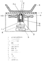
以下、本発明の実施例1について説明する。図1は本実施例の構成を示すブロック図である。図1において1は本実施例の誘導加熱調理器の本体である。6は加熱コイル、7はトッププレート、8は鍋である。
【0024】
2は鍋8の底面から放射されている赤外線の強さを検知するフォトダイオードであり、約1ミクロンから2.5ミクロンの波長の赤外線に対して感度が高く、その他の波長の赤外線に対しては感じないように設計されている。このフォトダイオードはもちろんPINフォトダイオードでも一向に差し支えない。2aはフォトダイオード2を支えるプリント基板である。3は熱伝導率の低い樹脂でできた円筒状の鏡筒であり、筒の内面3aは赤外線をよく反射するようにアルミメッキ加工されている。
【0025】
また、鏡筒3の内径はフォトダイオード2に比べて大きくしている。これは鏡筒3の上端がトッププレート7に近いため、調理時は鏡筒3は高温になる。鏡筒3の内径をフォトダイオード2よりも大きくしておくことでフォトダイオード2が鏡筒3の温度の影響を受けにくくしている。
【0026】
9はアルミでできた円筒であり、加熱コイル6から出されている高周波磁界が鏡筒3の内側に悪影響を与えないよう遮蔽するものである。10は鏡筒3の上端とトッププレート7の下面との間に挟みこんでいるリング状のパッキンであり、油煙やゴミが鏡筒3の内部に入り込み、フォトダイオード2の受光窓につかないようにしている。この鏡筒3の上端部だけの内径を細くすることも油煙等の侵入を防ぐには有効である。図2はこの鏡筒3の上端部だけの内径を細くした場合の一実施例を示す構成図である。図2において図1と同じ構成物には同じ番号を付している。
【0027】
さらに、図1において4は温度算出手段であり、フォトダイオード2の出力信号から鍋8の温度を算出する。制御手段5は温度算出手段4の出力に応じて加熱コイル6に供給する電力を制御する。
【0028】
11はサーミスタなどの温度検知素子であり、フォトダイオード2の温度を測定するためのものである。一般にフォトダイオードは受光していなくても暗電流というわずかな電流が流れてしまう。そして、この暗電流は温度が高くなると増大するという性質がある。鍋の温度が低く受光赤外線エネルギーが少ない時のフォトダイオード2にも同じく暗電流が発生するが、そのときのフォトダイオード2の温度によって暗電流の大きさは異なる。サーミスタ11は絶対に必要なものではないが、フォトダイオード2の温度を検知し、鍋の温度が低いときに生じる暗電流の温度による変化を補償するために用いている。
【0029】
次に動作について説明する。図示していない電源を投入し、操作スイッチで所定の温度を設定すると、制御手段5が加熱コイル6に約20kHzの高周波電力を供給する。加熱コイル6に高周波電力が供給されると、加熱コイル6から誘導磁界が発せられ、トッププレート7上の鍋8に誘導電流が流れジュール熱によって鍋底が加熱される。
【0030】
一般に物体の放射する赤外線エネルギーはその物体の絶対温度の4乗に比例するというステファン・ボルツマンの法則があり、温度が高くなればなるほど加速度的に大きなエネルギーを赤外線として放射する。フォトダイオード2は受光した赤外線のエネルギーに比例した電流を出力するもので、インジウムとガリウムと砒素などの化合物半導体を用いて製造されている。このため、鍋8の温度が上昇すると鍋底からの赤外線放射強度も強くなり、フォトダイオード2が受光する赤外線エネルギー量が増え、フォトダイオード2の出力電流も多くなる。温度算出手段4にはフォトダイオード2の信号電流を電圧に変換する電流電圧変換回路も組み込まれている。
【0031】
また、温度算出手段4はフォトダイオード2の出力信号から鍋8の温度を算出し、制御手段5に送る。制御手段5は、この温度信号に応じて加熱コイル6に供給する高周波電力を制御して、所定の鍋温度になるように制御する。
【0032】
トッププレート7は結晶化ガラスでできており、鍋から放射される赤外線のうち最もエネルギーの強い5ミクロン以上の波長の赤外線は透過しない。しかし、フォトダイオード2が敏感に検知できる2.5ミクロン以下の波長の赤外線は非常に良く透過する性質を持つ。
【0033】
一方、トッププレート7は5ミクロン以上の長い波長の赤外線は透過しないが、この波長の赤外線を自身の温度に相当する強度で放射する。しかし、フォトダイオード2は2.5ミクロン以下の赤外線にしか敏感に反応しないためトッププレート7からの長波長の赤外線放射に邪魔されず高精度に鍋底からの2.5ミクロン以下の短波長の赤外線を検知することができる。
【0034】
また、高温になるトッププレート7からフォトダイオード2を遠ざける必要があるが、加熱コイル6よりも下に配置すると今度は加熱コイル6からの赤外線を受けてしまう。鏡筒3を用いることで鏡筒3の上端から点線B、B’で示した視野角度で鍋8の底面を見るようにすることができ、加熱コイル6からの赤外線を受けないようにすることができる。
【0035】
また、磁気遮蔽用のアルミでできた円筒9は、円筒内部への磁気の侵入を阻止する代わりに、加熱コイル6からの高周波磁界の影響で高周波電流が流れジュール熱によって発熱する。しかし、このアルミ製の円筒9と鏡筒3との間に空気層ができるように隙間を開けて配置することで空気断熱ができ、鏡筒3およびその内部のフォトダイオード2に円筒9の温度が影響を与えるということを防ぐことができる。
【0036】
このように鍋底の温度をトッププレート7を介して測定しているが、2.5ミクロン以下の赤外線を検知できるフォトダイオードを用いることでトッププレートからの赤外線放射の影響を受けずにトッププレートを透過してきた鍋底からの赤外線を検知でき正確に鍋底温度を算出することが可能である。
【0037】
また、鏡筒を用いることで鏡筒の上端から鍋底を見るようにすることができ、加熱コイルからの赤外線を受けないようにすることができる。
【0038】
また、鏡筒とフォトダイオードを接しないように配置し空気で断熱することでフォトダイオードが鏡筒の温度の影響を受けにくくすることができる。
【0039】
また、鏡筒の内径をフォトダイオードに比べて大きくすれば、フォトダイオードが鏡筒の温度の影響を受けにくくすることが容易にできる。
【0040】
また、鏡筒の上端とトッププレートの下面との間にリング状のパッキンを挟むことで、油煙やゴミが鏡筒の内部に入り込みフォトダイオードの受光窓を曇らせることが無いようにできる。
【0041】
また、鏡筒を熱伝導率の低い樹脂で構成し、円筒の内面をアルミメッキするか、円筒の内面にアルミ箔のテープを貼ることで、トッププレートの温度をフォトダイオードの近くにまで伝えにくい鏡筒を構成することができる。
【0042】
また、鏡筒の外周に金属製円筒を配置し加熱コイルからの誘導磁界が鏡筒の内部に影響しないよう遮蔽する構成にすることでフォトダイオードが誘導磁界の影響を受けて出力信号に誤りを生じるというようなことを防ぐことができる。
【0043】
また、フォトダイオードの温度を検知する温度検知素子をフォトダイオードの近傍に配置することで、鍋温度が低いため受光赤外線エネルギーが少ない時にフォトダイオードの暗電流の温度変化を補償することができる。
【0044】
また、鏡筒の外側に配置した磁気遮蔽用の金属製円筒と鏡筒との間に断熱層を設けることでフォトダイオードを熱的に安定させ、より高精度な温度測定ができる。
【0045】
また、鏡筒の上端部の内径を鏡筒の下部の内径よりも細くすることで、鏡筒がフォトダイオードに接することなく、熱的に結合させない構造にするとともに、油煙などが鏡筒内部に入り込み難くい構成を実現できる。
【0046】
【発明の効果】
以上のように本発明によれば、フォトダイオードでトッププレートを透過してくる鍋底からの短波長の赤外線だけを検知し、トッププレートから放射される大きなエネルギー量の長波長の赤外線には影響を受けず、さらに、赤外線検知の原理が量子型であるため、熱型の原理で動作するサーモパイル等の赤外線センサにくらべサーモパイル等のように赤外線センサ自身の温度を測定する必要も無く、また、周囲温度の変化にも影響を受け難いため、高精度に温度検知が行える誘導加熱調理器を実現できるものである。
【図面の簡単な説明】
【図1】本発明の実施例1における誘導加熱調理器を示すブロック図
【図2】本発明の実施例1における先端部内径が細い鏡筒の場合の誘導加熱調理器を示すブロック図
【図3】従来における第1の誘導加熱調理器を示すブロック図
【図4】従来における第2の誘導加熱調理器を示すブロック図
【符号の説明】
1 本体
2 赤外線センサ
2a プリント基板
3 鏡筒
3a アルミメッキ
4 温度算出手段
5 制御手段
6 加熱コイル
7 トッププレート
8 鍋
9 円筒
10 パッキン
11 温度検知素子[0001]
TECHNICAL FIELD OF THE INVENTION
The present invention relates to an induction heating cooker that can accurately detect the temperature of a pan on a top plate.
[0002]
[Prior art]
In a conventional induction heating cooker, the temperature of the bottom of the pot is detected by a thermosensitive element such as a thermistor brought into contact with a top plate on which the pot is placed. In addition, there is an apparatus that detects infrared rays emitted from the bottom of the pan with an infrared sensor through a top plate to detect the temperature of the bottom of the pan (for example, see Patent Document 1).
[0003]
Further, there is also a method in which a temperature of a pot bottom and a temperature change gradient are detected by using both a thermosensitive element in contact with a top plate and an infrared sensor (for example, see Patent Document 2).
[0004]
FIG. 3 is a configuration diagram of a conventional infrared sensor induction heating cooker. The
[0005]
[Patent Document 1]
JP 03-184295 A [Patent Document 2]
Japanese Patent Application Laid-Open No. 03-208288
[Problems to be solved by the invention]
The induction heating cooker having the conventional configuration shown in FIG. 3 detects infrared rays emitted from the
[0007]
The inventors have repeatedly used thermopiles as infrared sensors and incorporated them in induction heating cookers. Since the thermopile is a thermal infrared sensor, when the temperature of the light receiving surface rises due to the effect of increasing the temperature of the received infrared light, a voltage is generated from multiple thermocouples arranged on the minute light receiving surface, which is amplified and amplified. Is to detect the temperature. Therefore, in order to use the thermopile effectively, it is necessary to irradiate infrared rays having a wavelength region (5 μm or more) excellent in temperature raising effect.
[0008]
However, as described above, the infrared ray that best passes through the top plate has a wavelength of 2.5 μm or less, and only the infrared ray whose temperature change on the light receiving surface of the thermopile hardly appears is passed. For this reason, it was necessary to connect an amplifier having a large amplification factor of 100,000 or more to the output of the thermopile.
[0009]
Further, since the thermopile is a thermal sensor, the temperature of the object is calculated from the voltage obtained from the light receiving surface based on the temperature of the sensor itself. Therefore, if the temperature of the sensor itself is not stable, the temperature of the target object cannot be accurately calculated. Particularly, in the induction heating cooker, the temperature around the sensor starts to rise as soon as cooking starts, so that it is extremely difficult to measure the pot bottom temperature stably. For this reason, the thermopile is placed downward to separate it from the
[0010]
In addition, the thermopile has a wide range of infrared wavelengths to be detected, and the wavelength of infrared rays radiated from the top plate to the lower surface is broad, including infrared rays of 5 microns or more, which have the highest energy, and penetrates the top plate from the bottom of the pot. The energy of the infrared radiation emitted from the top plate toward the lower surface is much stronger than the infrared radiation coming. To suppress this problem, the inventors have tried placing a filter on the thermopile that cuts infrared rays having a wavelength longer than 5 microns of infrared rays emitted from the top plate toward the lower surface. However, since the long-wavelength infrared rays are radiated from the long-wavelength cut filter due to its own temperature, the cause of the measurement error is eventually increased.
[0011]
On the other hand, the inventors have attempted to make a hole in the top plate and embed an infrared transmitting material that transmits infrared light having a long wavelength well in the hole. Artificial sapphire or the like is suitable for this infrared transmitting material. Since this artificial sapphire is expensive, it has been avoided to make a large hole so that the artificial sapphire can be used in a small amount. Since the viewing angle of the thermopile is wide and the light receiving sensitivity is almost all over 180 °, when the diameter of the hole formed in the top plate is reduced, as shown in FIG. It was necessary to narrow the field of view of the thermopile using a
[0012]
[Means for Solving the Problems]
The present invention provides a heating coil that heats a pan, a top plate on which the pan is placed above the heating coil, a photodiode that is placed on the lower surface of the top plate and detects the intensity of infrared radiation emitted from the bottom of the pan, Temperature calculating means for calculating the temperature of the bottom of the pot from the output of the photodiode, and control means for controlling the power supplied to the heating coil according to the output of the temperature calculating means, transmitted through the top plate by the photodiode It reacts only to short-wave infrared rays from the bottom of the pot, does not react to long-wave infrared rays with a large amount of energy radiated from the top plate.Furthermore, since the principle of infrared detection is quantum type, thermal type There is no need to measure the temperature of the infrared sensor itself, such as a thermopile, as compared to an infrared sensor such as a thermopile, which operates on the principle of Since hardly affected changes in ambient temperature, but that the induction heating cooker capable of performing temperature detection with high accuracy.
[0013]
BEST MODE FOR CARRYING OUT THE INVENTION
According to the first aspect of the present invention, a heating coil for heating the pan, a top plate on which the pan is placed above the heating coil, and an infrared intensity radiated from the bottom of the pan placed on the lower surface of the top plate are detected. A photodiode, temperature calculating means for calculating the temperature of the bottom surface of the pot from the output of the photodiode, control means for controlling the power supplied to the heating coil according to the output of the temperature calculating means, and blocking transmission of light. A lens barrel formed of a material and formed in a substantially cylindrical shape, wherein the lens barrel is arranged to limit light incident on the photodiode, and the photodiode is transmitted through the top plate. Responds to infrared rays coming from the bottom of the pot, but does not respond to long-wavelength infrared rays with a large amount of energy radiated from the top plate. In order to detect well, quantum type infrared detection is used, and the photodiode reacts only to infrared light from the bottom of the pot that penetrates the top plate with the photodiode. Is to detect only infrared rays from the bottom of the pot by not reacting.In addition, since the principle of infrared detection is a quantum type, infrared rays such as thermopiles operate in comparison with infrared sensors such as thermopiles that operate on the principle of heat type. It is not necessary to correct the calculated temperature by measuring the temperature of the sensor itself, and it is hardly affected by changes in the ambient temperature, so it is an induction heating cooker that can measure the pot temperature with high accuracy. .
[0014]
According to the second aspect of the present invention, it is possible to dispose the photodiode away from the top plate or the heating coil which becomes high temperature by disposing the lens barrel for limiting the field of view of the photodiode in the first aspect of the invention. The induction heating cooker described above.
[0015]
According to the third aspect of the present invention, an induction heating cooker having a structure provided with a means for reducing heat conduction from a lens barrel to a photodiode is provided, so that temperature can be measured more thermally. Is what it is.
[0016]
According to a fourth aspect of the present invention, in the third aspect, the inner diameter of the lens barrel is larger than the outer diameter of the photodiode, so that the lens barrel does not contact the photodiode and is not thermally coupled. The induction heating cooker is capable of performing temperature measurement while being thermally stable.
[0017]
According to a fifth aspect of the present invention, there is provided a packing structure for preventing air from flowing into the inside of the lens barrel according to the second to fourth aspects of the present invention, which is disposed between the lower surface of the top plate and the upper end of the lens barrel. Is an induction heating cooker in which the light-receiving window of the photodiode does not fog into the inside of the lens barrel.
[0018]
The invention described in
[0019]
According to a seventh aspect of the present invention, in the second to sixth aspects of the present invention, a metal cylinder is arranged on the outer periphery of the lens barrel to shield the magnetic field induced from the heating coil from affecting the inside of the lens barrel. It is an induction heating cooker.
[0020]
According to an eighth aspect of the present invention, there is provided the temperature detecting element for detecting the temperature of the photodiode in the first to seventh aspects of the present invention, and the temperature change of the dark current of the photodiode when the received infrared ray energy is small is compensated. It is an induction heating cooker.
[0021]
According to a ninth aspect of the present invention, in the invention according to the seventh or eighth aspect, a heat insulating layer is provided between the lens barrel and the outer metal cylinder to thermally stabilize the photodiode, thereby achieving more accurate temperature control. It is an induction heating cooker that can measure.
[0022]
According to a tenth aspect of the present invention, in the inventions of the second to ninth aspects, the inside diameter of the upper end portion of the lens barrel is made smaller than the inside diameter of the lower portion of the lens barrel, so that oil smoke and the like hardly enter the inside of the lens barrel. It is an induction heating cooker.
[0023]
【Example】
(Example 1)
Hereinafter,
[0024]
[0025]
The inner diameter of the
[0026]
[0027]
Further, in FIG. 1,
[0028]
[0029]
Next, the operation will be described. When a power supply (not shown) is turned on and a predetermined temperature is set by an operation switch, the control means 5 supplies a high-frequency power of about 20 kHz to the
[0030]
Generally, there is Stefan-Boltzmann's law that the infrared energy emitted by an object is proportional to the fourth power of the absolute temperature of the object, and the higher the temperature, the more energy is radiated as infrared rays at an accelerated rate. The
[0031]
Further, the temperature calculating means 4 calculates the temperature of the
[0032]
The
[0033]
On the other hand, the
[0034]
Further, it is necessary to keep the
[0035]
In addition, the
[0036]
As described above, the temperature at the bottom of the pot is measured via the
[0037]
In addition, by using the lens barrel, the bottom of the pot can be seen from the upper end of the lens barrel, so that infrared rays from the heating coil can be prevented.
[0038]
Further, by disposing the barrel and the photodiode so as not to be in contact with each other and insulating the photodiode with air, the photodiode can be hardly affected by the temperature of the barrel.
[0039]
Further, if the inner diameter of the lens barrel is made larger than that of the photodiode, it is easy to make the photodiode less affected by the temperature of the lens barrel.
[0040]
Further, by sandwiching the ring-shaped packing between the upper end of the lens barrel and the lower surface of the top plate, it is possible to prevent oil smoke and dust from entering the inside of the lens barrel and fogging the light receiving window of the photodiode.
[0041]
In addition, it is difficult to transmit the temperature of the top plate to the vicinity of the photodiode by forming the lens barrel with a resin with low thermal conductivity and plating the inner surface of the cylinder with aluminum or attaching aluminum foil tape to the inner surface of the cylinder. A lens barrel can be configured.
[0042]
In addition, a metal cylinder is placed around the outer periphery of the lens barrel to shield the induced magnetic field from the heating coil from affecting the inside of the lens barrel. That can be prevented.
[0043]
Further, by disposing the temperature detecting element for detecting the temperature of the photodiode near the photodiode, it is possible to compensate for the temperature change of the dark current of the photodiode when the received infrared energy is small due to the low pot temperature.
[0044]
Further, by providing a heat insulating layer between the metal cylinder for magnetic shielding disposed outside the lens barrel and the lens barrel, the photodiode is thermally stabilized, and more accurate temperature measurement can be performed.
[0045]
In addition, by making the inner diameter of the upper end of the lens barrel smaller than the inner diameter of the lower part of the lens barrel, the lens barrel does not come into contact with the photodiode and is not thermally coupled. A configuration that is difficult to enter can be realized.
[0046]
【The invention's effect】
As described above, according to the present invention, the photodiode detects only short-wavelength infrared rays from the bottom of the pot that pass through the top plate, and has an effect on long-wavelength infrared rays with a large amount of energy emitted from the top plate. No, and because the principle of infrared detection is of the quantum type, there is no need to measure the temperature of the infrared sensor itself, unlike a thermopile or the like, which operates based on the principle of thermal type. Since it is hardly affected by a change in temperature, it is possible to realize an induction heating cooker that can perform temperature detection with high accuracy.
[Brief description of the drawings]
FIG. 1 is a block diagram illustrating an induction heating cooker according to a first embodiment of the present invention. FIG. 2 is a block diagram illustrating an induction heating cooker according to a first embodiment of the present invention in the case of a lens barrel having a small tip inside diameter. 3 is a block diagram showing a conventional first induction heating cooker. FIG. 4 is a block diagram showing a conventional second induction heating cooker.
DESCRIPTION OF
Claims (10)
Priority Applications (1)
| Application Number | Priority Date | Filing Date | Title |
|---|---|---|---|
| JP2003015864A JP2004227976A (en) | 2003-01-24 | 2003-01-24 | Induction heating cooker |
Applications Claiming Priority (1)
| Application Number | Priority Date | Filing Date | Title |
|---|---|---|---|
| JP2003015864A JP2004227976A (en) | 2003-01-24 | 2003-01-24 | Induction heating cooker |
Related Child Applications (2)
| Application Number | Title | Priority Date | Filing Date |
|---|---|---|---|
| JP2007308486A Division JP4277927B2 (en) | 2007-11-29 | 2007-11-29 | Induction heating cooker |
| JP2009159671A Division JP2009224340A (en) | 2009-07-06 | 2009-07-06 | Induction heating cooking device |
Publications (1)
| Publication Number | Publication Date |
|---|---|
| JP2004227976A true JP2004227976A (en) | 2004-08-12 |
Family
ID=32903499
Family Applications (1)
| Application Number | Title | Priority Date | Filing Date |
|---|---|---|---|
| JP2003015864A Pending JP2004227976A (en) | 2003-01-24 | 2003-01-24 | Induction heating cooker |
Country Status (1)
| Country | Link |
|---|---|
| JP (1) | JP2004227976A (en) |
Cited By (16)
| Publication number | Priority date | Publication date | Assignee | Title |
|---|---|---|---|---|
| JP2007227135A (en) * | 2006-02-23 | 2007-09-06 | Matsushita Electric Ind Co Ltd | Induction heating device |
| JP2007323887A (en) * | 2006-05-31 | 2007-12-13 | Matsushita Electric Ind Co Ltd | Induction heating device |
| JP2008181899A (en) * | 2008-04-21 | 2008-08-07 | Matsushita Electric Ind Co Ltd | Induction heating cooker |
| WO2008155922A1 (en) * | 2007-06-21 | 2008-12-24 | Panasonic Corporation | Induction heating cooker |
| WO2009001538A1 (en) * | 2007-06-22 | 2008-12-31 | Panasonic Corporation | Induction cooker |
| JP2009252633A (en) * | 2008-04-09 | 2009-10-29 | Toshiba Corp | Induction heating cooking device |
| JP2009259608A (en) * | 2008-04-17 | 2009-11-05 | Hitachi Appliances Inc | Induction cooker |
| JP2009259835A (en) * | 2009-05-25 | 2009-11-05 | Hitachi Appliances Inc | Induction cooker |
| JP2009259836A (en) * | 2009-05-25 | 2009-11-05 | Hitachi Appliances Inc | Induction cooker |
| WO2010100697A1 (en) * | 2009-03-04 | 2010-09-10 | パナソニック株式会社 | Induction heating device |
| WO2011132614A1 (en) * | 2010-04-21 | 2011-10-27 | 三菱電機株式会社 | Induction cooker |
| JP2013062188A (en) * | 2011-09-14 | 2013-04-04 | Toshiba Corp | Induction heating cooker |
| JP2013101835A (en) * | 2011-11-09 | 2013-05-23 | Hitachi Appliances Inc | Induction heating cooker |
| EP2775787A1 (en) * | 2013-03-04 | 2014-09-10 | Miele & Cie. KG | Cooking device |
| CN109282330A (en) * | 2018-11-09 | 2019-01-29 | 杭州老板电器股份有限公司 | Infrared measurement of temperature electromagnetic stove |
| EP3515154A1 (en) * | 2013-03-04 | 2019-07-24 | Miele & Cie. KG | Cooking device |
-
2003
- 2003-01-24 JP JP2003015864A patent/JP2004227976A/en active Pending
Cited By (22)
| Publication number | Priority date | Publication date | Assignee | Title |
|---|---|---|---|---|
| JP2007227135A (en) * | 2006-02-23 | 2007-09-06 | Matsushita Electric Ind Co Ltd | Induction heating device |
| JP2007323887A (en) * | 2006-05-31 | 2007-12-13 | Matsushita Electric Ind Co Ltd | Induction heating device |
| WO2008155922A1 (en) * | 2007-06-21 | 2008-12-24 | Panasonic Corporation | Induction heating cooker |
| JP2009004212A (en) * | 2007-06-21 | 2009-01-08 | Panasonic Corp | Induction-heating cooker |
| US8203106B2 (en) | 2007-06-22 | 2012-06-19 | Panasonic Corporation | Induction heating appliance for cooking |
| WO2009001538A1 (en) * | 2007-06-22 | 2008-12-31 | Panasonic Corporation | Induction cooker |
| JP2009252633A (en) * | 2008-04-09 | 2009-10-29 | Toshiba Corp | Induction heating cooking device |
| JP2009259608A (en) * | 2008-04-17 | 2009-11-05 | Hitachi Appliances Inc | Induction cooker |
| JP4497225B2 (en) * | 2008-04-21 | 2010-07-07 | パナソニック株式会社 | Induction heating cooker |
| JP2008181899A (en) * | 2008-04-21 | 2008-08-07 | Matsushita Electric Ind Co Ltd | Induction heating cooker |
| WO2010100697A1 (en) * | 2009-03-04 | 2010-09-10 | パナソニック株式会社 | Induction heating device |
| JP2010205575A (en) * | 2009-03-04 | 2010-09-16 | Panasonic Corp | Induction heating device |
| US9414443B2 (en) | 2009-03-04 | 2016-08-09 | Panasonic Intellectual Property Management Co., Ltd. | Induction heating device |
| JP2009259835A (en) * | 2009-05-25 | 2009-11-05 | Hitachi Appliances Inc | Induction cooker |
| JP2009259836A (en) * | 2009-05-25 | 2009-11-05 | Hitachi Appliances Inc | Induction cooker |
| JP5340479B2 (en) * | 2010-04-21 | 2013-11-13 | 三菱電機株式会社 | Induction heating cooker |
| WO2011132614A1 (en) * | 2010-04-21 | 2011-10-27 | 三菱電機株式会社 | Induction cooker |
| JP2013062188A (en) * | 2011-09-14 | 2013-04-04 | Toshiba Corp | Induction heating cooker |
| JP2013101835A (en) * | 2011-11-09 | 2013-05-23 | Hitachi Appliances Inc | Induction heating cooker |
| EP2775787A1 (en) * | 2013-03-04 | 2014-09-10 | Miele & Cie. KG | Cooking device |
| EP3515154A1 (en) * | 2013-03-04 | 2019-07-24 | Miele & Cie. KG | Cooking device |
| CN109282330A (en) * | 2018-11-09 | 2019-01-29 | 杭州老板电器股份有限公司 | Infrared measurement of temperature electromagnetic stove |
Similar Documents
| Publication | Publication Date | Title |
|---|---|---|
| JP4277927B2 (en) | Induction heating cooker | |
| JP2004227976A (en) | Induction heating cooker | |
| JP2002075624A (en) | Induction heating cooker | |
| JP5286140B2 (en) | Induction heating cooker | |
| JP4123036B2 (en) | Cooker | |
| JP5517720B2 (en) | Induction heating cooker | |
| JP2011216323A (en) | Induction heating cooker | |
| JP2004095314A (en) | Induction heating cooker | |
| JP4089444B2 (en) | Cooker | |
| JP5244861B2 (en) | Induction heating cooker | |
| JP2004095313A (en) | Induction heating cooker | |
| JP5537505B2 (en) | Induction heating cooker | |
| JP2003317920A (en) | Induction heating cooking device | |
| JP6512689B2 (en) | Induction cooker | |
| TWI524819B (en) | Induction cooktop | |
| JP5341385B2 (en) | Induction heating cooker | |
| JP2006292439A (en) | Temperature detection device | |
| JP4178966B2 (en) | Cooker | |
| JP2009224340A (en) | Induction heating cooking device | |
| JP2010244999A (en) | Induction heating cooker | |
| JP5868483B2 (en) | Induction heating cooker | |
| JP6506568B2 (en) | Induction cooker | |
| JP5677263B2 (en) | Induction heating cooker | |
| JP5135386B2 (en) | Induction heating cooker | |
| JP2017216191A (en) | Induction heating cooker |
Legal Events
| Date | Code | Title | Description |
|---|---|---|---|
| A621 | Written request for application examination |
Free format text: JAPANESE INTERMEDIATE CODE: A621 Effective date: 20051115 |
|
| RD01 | Notification of change of attorney |
Free format text: JAPANESE INTERMEDIATE CODE: A7421 Effective date: 20051213 |
|
| A977 | Report on retrieval |
Free format text: JAPANESE INTERMEDIATE CODE: A971007 Effective date: 20070702 |
|
| A131 | Notification of reasons for refusal |
Free format text: JAPANESE INTERMEDIATE CODE: A131 Effective date: 20071009 |
|
| A521 | Written amendment |
Free format text: JAPANESE INTERMEDIATE CODE: A523 Effective date: 20071129 |
|
| A131 | Notification of reasons for refusal |
Free format text: JAPANESE INTERMEDIATE CODE: A131 Effective date: 20080610 |
|
| A02 | Decision of refusal |
Free format text: JAPANESE INTERMEDIATE CODE: A02 Effective date: 20090407 |
|
| A521 | Written amendment |
Free format text: JAPANESE INTERMEDIATE CODE: A523 Effective date: 20090706 |
|
| A911 | Transfer of reconsideration by examiner before appeal (zenchi) |
Free format text: JAPANESE INTERMEDIATE CODE: A911 Effective date: 20090714 |
|
| A912 | Removal of reconsideration by examiner before appeal (zenchi) |
Free format text: JAPANESE INTERMEDIATE CODE: A912 Effective date: 20090918 |