EP2772357B1 - Fluid injection device - Google Patents
Fluid injection device Download PDFInfo
- Publication number
- EP2772357B1 EP2772357B1 EP14163529.2A EP14163529A EP2772357B1 EP 2772357 B1 EP2772357 B1 EP 2772357B1 EP 14163529 A EP14163529 A EP 14163529A EP 2772357 B1 EP2772357 B1 EP 2772357B1
- Authority
- EP
- European Patent Office
- Prior art keywords
- flow passage
- fluid
- inlet flow
- fluid chamber
- inlet
- Prior art date
- Legal status (The legal status is an assumption and is not a legal conclusion. Google has not performed a legal analysis and makes no representation as to the accuracy of the status listed.)
- Active
Links
- 239000012530 fluid Substances 0.000 title claims description 236
- 238000002347 injection Methods 0.000 title claims description 43
- 239000007924 injection Substances 0.000 title claims description 43
- 238000012856 packing Methods 0.000 claims description 13
- 230000002093 peripheral effect Effects 0.000 description 36
- 230000003014 reinforcing effect Effects 0.000 description 34
- 238000007789 sealing Methods 0.000 description 14
- 238000010276 construction Methods 0.000 description 13
- 230000037237 body shape Effects 0.000 description 11
- 238000003780 insertion Methods 0.000 description 11
- 230000037431 insertion Effects 0.000 description 11
- 230000037452 priming Effects 0.000 description 11
- 238000000034 method Methods 0.000 description 10
- 230000008569 process Effects 0.000 description 8
- 230000008859 change Effects 0.000 description 7
- 239000007788 liquid Substances 0.000 description 6
- 238000005530 etching Methods 0.000 description 5
- 239000000853 adhesive Substances 0.000 description 4
- 230000001070 adhesive effect Effects 0.000 description 4
- 230000008901 benefit Effects 0.000 description 3
- 238000009792 diffusion process Methods 0.000 description 3
- 238000007599 discharging Methods 0.000 description 3
- 238000003825 pressing Methods 0.000 description 3
- 230000009467 reduction Effects 0.000 description 3
- 230000003252 repetitive effect Effects 0.000 description 3
- 239000007787 solid Substances 0.000 description 3
- 238000001356 surgical procedure Methods 0.000 description 3
- 238000003466 welding Methods 0.000 description 3
- 238000009825 accumulation Methods 0.000 description 2
- 230000009471 action Effects 0.000 description 2
- 238000001574 biopsy Methods 0.000 description 2
- 230000015556 catabolic process Effects 0.000 description 2
- 238000005520 cutting process Methods 0.000 description 2
- 238000006731 degradation reaction Methods 0.000 description 2
- 238000010586 diagram Methods 0.000 description 2
- 230000000694 effects Effects 0.000 description 2
- 238000004519 manufacturing process Methods 0.000 description 2
- 229910000679 solder Inorganic materials 0.000 description 2
- FAPWRFPIFSIZLT-UHFFFAOYSA-M Sodium chloride Chemical compound [Na+].[Cl-] FAPWRFPIFSIZLT-UHFFFAOYSA-M 0.000 description 1
- 210000004556 brain Anatomy 0.000 description 1
- 239000012141 concentrate Substances 0.000 description 1
- 230000008030 elimination Effects 0.000 description 1
- 238000003379 elimination reaction Methods 0.000 description 1
- 238000009434 installation Methods 0.000 description 1
- 230000003993 interaction Effects 0.000 description 1
- 238000005304 joining Methods 0.000 description 1
- 238000002844 melting Methods 0.000 description 1
- 238000012986 modification Methods 0.000 description 1
- 230000004048 modification Effects 0.000 description 1
- 238000007747 plating Methods 0.000 description 1
- 238000003672 processing method Methods 0.000 description 1
- 230000002787 reinforcement Effects 0.000 description 1
- 238000004659 sterilization and disinfection Methods 0.000 description 1
- XLYOFNOQVPJJNP-UHFFFAOYSA-N water Substances O XLYOFNOQVPJJNP-UHFFFAOYSA-N 0.000 description 1
Images


Classifications
-
- B—PERFORMING OPERATIONS; TRANSPORTING
- B05—SPRAYING OR ATOMISING IN GENERAL; APPLYING FLUENT MATERIALS TO SURFACES, IN GENERAL
- B05B—SPRAYING APPARATUS; ATOMISING APPARATUS; NOZZLES
- B05B1/00—Nozzles, spray heads or other outlets, with or without auxiliary devices such as valves, heating means
- B05B1/02—Nozzles, spray heads or other outlets, with or without auxiliary devices such as valves, heating means designed to produce a jet, spray, or other discharge of particular shape or nature, e.g. in single drops, or having an outlet of particular shape
- B05B1/08—Nozzles, spray heads or other outlets, with or without auxiliary devices such as valves, heating means designed to produce a jet, spray, or other discharge of particular shape or nature, e.g. in single drops, or having an outlet of particular shape of pulsating nature, e.g. delivering liquid in successive separate quantities ; Fluidic oscillators
- B05B1/083—Nozzles, spray heads or other outlets, with or without auxiliary devices such as valves, heating means designed to produce a jet, spray, or other discharge of particular shape or nature, e.g. in single drops, or having an outlet of particular shape of pulsating nature, e.g. delivering liquid in successive separate quantities ; Fluidic oscillators the pulsating mechanism comprising movable parts
- B05B1/086—Nozzles, spray heads or other outlets, with or without auxiliary devices such as valves, heating means designed to produce a jet, spray, or other discharge of particular shape or nature, e.g. in single drops, or having an outlet of particular shape of pulsating nature, e.g. delivering liquid in successive separate quantities ; Fluidic oscillators the pulsating mechanism comprising movable parts with a resiliently deformable element, e.g. sleeve
-
- A—HUMAN NECESSITIES
- A61—MEDICAL OR VETERINARY SCIENCE; HYGIENE
- A61B—DIAGNOSIS; SURGERY; IDENTIFICATION
- A61B17/00—Surgical instruments, devices or methods, e.g. tourniquets
- A61B17/32—Surgical cutting instruments
- A61B17/3203—Fluid jet cutting instruments
-
- A—HUMAN NECESSITIES
- A61—MEDICAL OR VETERINARY SCIENCE; HYGIENE
- A61B—DIAGNOSIS; SURGERY; IDENTIFICATION
- A61B10/00—Other methods or instruments for diagnosis, e.g. instruments for taking a cell sample, for biopsy, for vaccination diagnosis; Sex determination; Ovulation-period determination; Throat striking implements
- A61B10/02—Instruments for taking cell samples or for biopsy
-
- B—PERFORMING OPERATIONS; TRANSPORTING
- B05—SPRAYING OR ATOMISING IN GENERAL; APPLYING FLUENT MATERIALS TO SURFACES, IN GENERAL
- B05B—SPRAYING APPARATUS; ATOMISING APPARATUS; NOZZLES
- B05B17/00—Apparatus for spraying or atomising liquids or other fluent materials, not covered by the preceding groups
- B05B17/04—Apparatus for spraying or atomising liquids or other fluent materials, not covered by the preceding groups operating with special methods
- B05B17/06—Apparatus for spraying or atomising liquids or other fluent materials, not covered by the preceding groups operating with special methods using ultrasonic or other kinds of vibrations
- B05B17/0607—Apparatus for spraying or atomising liquids or other fluent materials, not covered by the preceding groups operating with special methods using ultrasonic or other kinds of vibrations generated by electrical means, e.g. piezoelectric transducers
- B05B17/0653—Details
-
- B—PERFORMING OPERATIONS; TRANSPORTING
- B26—HAND CUTTING TOOLS; CUTTING; SEVERING
- B26F—PERFORATING; PUNCHING; CUTTING-OUT; STAMPING-OUT; SEVERING BY MEANS OTHER THAN CUTTING
- B26F3/00—Severing by means other than cutting; Apparatus therefor
- B26F3/004—Severing by means other than cutting; Apparatus therefor by means of a fluid jet
-
- B—PERFORMING OPERATIONS; TRANSPORTING
- B41—PRINTING; LINING MACHINES; TYPEWRITERS; STAMPS
- B41J—TYPEWRITERS; SELECTIVE PRINTING MECHANISMS, i.e. MECHANISMS PRINTING OTHERWISE THAN FROM A FORME; CORRECTION OF TYPOGRAPHICAL ERRORS
- B41J2/00—Typewriters or selective printing mechanisms characterised by the printing or marking process for which they are designed
- B41J2/005—Typewriters or selective printing mechanisms characterised by the printing or marking process for which they are designed characterised by bringing liquid or particles selectively into contact with a printing material
- B41J2/01—Ink jet
- B41J2/17—Ink jet characterised by ink handling
- B41J2/175—Ink supply systems ; Circuit parts therefor
- B41J2/17596—Ink pumps, ink valves
-
- B—PERFORMING OPERATIONS; TRANSPORTING
- B41—PRINTING; LINING MACHINES; TYPEWRITERS; STAMPS
- B41J—TYPEWRITERS; SELECTIVE PRINTING MECHANISMS, i.e. MECHANISMS PRINTING OTHERWISE THAN FROM A FORME; CORRECTION OF TYPOGRAPHICAL ERRORS
- B41J2/00—Typewriters or selective printing mechanisms characterised by the printing or marking process for which they are designed
- B41J2/005—Typewriters or selective printing mechanisms characterised by the printing or marking process for which they are designed characterised by bringing liquid or particles selectively into contact with a printing material
- B41J2/01—Ink jet
- B41J2/17—Ink jet characterised by ink handling
- B41J2/19—Ink jet characterised by ink handling for removing air bubbles
-
- B—PERFORMING OPERATIONS; TRANSPORTING
- B65—CONVEYING; PACKING; STORING; HANDLING THIN OR FILAMENTARY MATERIAL
- B65D—CONTAINERS FOR STORAGE OR TRANSPORT OF ARTICLES OR MATERIALS, e.g. BAGS, BARRELS, BOTTLES, BOXES, CANS, CARTONS, CRATES, DRUMS, JARS, TANKS, HOPPERS, FORWARDING CONTAINERS; ACCESSORIES, CLOSURES, OR FITTINGS THEREFOR; PACKAGING ELEMENTS; PACKAGES
- B65D83/00—Containers or packages with special means for dispensing contents
-
- A—HUMAN NECESSITIES
- A61—MEDICAL OR VETERINARY SCIENCE; HYGIENE
- A61B—DIAGNOSIS; SURGERY; IDENTIFICATION
- A61B17/00—Surgical instruments, devices or methods, e.g. tourniquets
- A61B2017/00017—Electrical control of surgical instruments
- A61B2017/00137—Details of operation mode
- A61B2017/00154—Details of operation mode pulsed
Description
- The present invention relates to a fluid injection device. More specifically, embodiments of the present invention relate to a fluid injection device of simple construction that injects stable and strong pulses of fluid.
- Conventional fluid injection device as disclosed in the Japanese Unexamined Patent Application, First Publication No.
2005-152127 - This fluid injection device includes a micro-pump, a connection flow passage, and a connection tube.
- The micro-pump changes the volume of the pump chamber and discharges the fluid.
- The outlet flow passage of the micro-pump is connected to one end of the connection flow passage, and an opening (nozzle) made smaller than the diameter of the outlet flow passage is formed at another end of the connection flow passage.
- The connection tube has a rigidity that is adequate to transmit the pulses of the fluid flowing from the micro-pump in which the connection flow passage to the opening is formed.
- The fluid flows in this fluid injection device by repetitive pulse wave trains and pauses, and is injected at high speed from the opening.
- In the Japanese Unexamined Patent Application, First Publication No.
2005-307743 - According to this art, the priming operation is performed at start when fluid has not entered the micro-pump, and the air in the pump chamber is compressed and removed after the start of operation.
- According to Japanese Unexamined Patent Application, First Publication No.
2005-152127 - While the ability to dissect tissues during surgery, for example, is high, the quantity of injection of pulsating fluid was low, and fluid rarely accumulated in the surgical field.
- Consequently, visibility was enhanced and the scattering of tissues was effectively prevented.
- This micro-pump required priming operation and elimination of air bubbles in the pump chamber at the start of operation based on the operating characteristics, and a construction with installation of the pump priming device as disclosed in the Japanese Unexamined Patent Application, First Publication No.
2005-307743 - However, even if a pump priming device is installed, the priming device is disconnected and removed after start, and when air bubbles are generated in the pump chamber, the drive operation may become unstable.
- Also, in the micro-pump according to the Japanese Unexamined Patent Applications, First Publication No.
2005-152127 2005-307743 - This check valve is extremely small, and its washability is poor. Also, the check valve may not be able to maintain adequate performance for long period use or repetitive use.
- Japanese Unexamined Patent Application, First Publication No.
2005-152127 - The invention provides a biological tissue incising device for injecting fluid to biological tissue, comprising: a fluid chamber, an inlet flow passage and an outlet flow passage that are connected to the fluid chamber; a connection flow passage configured to be connected to the outlet flow passage, having a fluid injection opening with a diameter smaller than the diameter of the outlet flow passage; and a pressure generation section configured to supply fluid to the inlet flow passage, characterised in that an inertance of the inlet flow passage is set greater than an inertance of the outlet flow passage.
- It is desirable to provide a fluid injection device in which it is.possible to realize a simple construction having high reliability, to eliminate degradation in performance due to accumulation of air bubbles during operation, and it is not necessary a priming device.
- As the pressure generation section, a pump discharging fluid at constant pressure may be used, for example.
- According to an embodiment of the invention, the fluid is supplied to the inlet flow passage at a constant pressure from the pressure generation section. Even if the drive of the pulse generation section is in the stop condition, fluid is supplied to the inlet flow passage and the fluid chamber. Therefore, priming operation is not required, and the initial operation can be started.
- Moreover, the fluid can be injected at high speed because fluid is injected from a fluid injection opening which has been made smaller than the diameter of the outlet flow passage.
- Furthermore, since the connection flow passage tube has adequate rigidity to transmit the pulses of the fluid flowing from the fluid chamber to the opening, the propagation of fluid pressure from the pulse generation section is not obstructed, and the desired pulse flow can be injected.
- In the fluid injection device of an embodiment of the invention, the inertance of the inlet flow passage is set greater than the inertance of the outlet flow passage.
- In this structure, by driving the pulse generation section, the pulse flow with inflow rate of fluid greater than that of the pulse flow from the inlet flow passage to the fluid chamber is generated in the outlet flow passage. The fluid in the pulsed state can be discharged into the connection flow passage tube.
- Consequently, there is no need to install a check valve on the inlet flow passage side, as in the Japanese Unexamined Patent Application, First Publication No.
2005-152127 - If the inertance of both the inlet flow passage and the outlet flow passage is set adequately great, and if the volume of the fluid chamber is abruptly reduced, then the pressure in the fluid chamber steeply increases.
- Thus, a pulse flow which is greater than that of the outlet flow passage can be generated.
- It is preferable that, in the fluid injection device, the pulse generation section includes a volume varying section for varying the volume of the fluid chamber, and the volume varying section include a piezoelectric element that expands or compresses the fluid chamber, and a diaphragm.
- If a piezoelectric element is used as to volume varying section, the structure can be simplified, and as a result the pulse generation section can be made smaller.
- The maximum frequency of change in volume of the fluid chamber can be set at greater than or equal to 1 kHz, which is ideal for injection of pulsed flow at high speed and at short repetitive periods.
- It is preferable that the fluid injection device further includes:
- a swirl flow generation section generating swirl flow of fluid around an axis of the fluid chamber. In this structure, the fluid chamber has a substantial rotating body shape, and includes an inner peripheral wall having a first end and a second end, a sealing surface sealing the first end of the inner peripheral wall, and a diaphragm sealing the second end of the inner peripheral wall. Also, in this structure, the outlet flow passage is formed at a portion which is closer to the axis of the substantial rotating body shape.
- The rotating body shape may be selected from cylindrical shape, conical shape, hemispherical shape, or the like.
- By generating a swirl flow in the fluid in the fluid chamber using the swirl flow generation section, the fluid is pushed toward the fluid chamber in the circumferential direction by centrifugal force. The air bubbles included in the fluid near the axis of the substantial rotating body shape accumulate at the center of the swirl flow. These air bubbles can be removed from the outlet flow passage formed at a portion which is closer to the axis of the substantial rotating body shape.
- As a result, the reduction in pressure amplitude due to the existence of air bubbles in the fluid chamber can be prevented. Also, the pulse generation section can be driven stably and continuously.
- It is preferable that, in the fluid injection device, the swirl flow generation section be formed by the inlet flow passage that connects the inner peripheral wall of the fluid chamber in a substantially tangential direction.
- In this structure, since the swirl flow generation section is formed by the inlet flow passage, swirl flow can be generated and there is no need to use a special swirl flow generation section.
- The inner peripheral wall of the fluid chamber is equivalent to the outer surface of the substantial rotating body shape.
- It is preferable that, in the fluid injection device, the inlet flow passage be formed on the peripheral edge of the fluid chamber.
- To form an inlet flow passage in this structure, a groove may be formed on the peripheral edge of the fluid chamber, for example, as the inlet flow passage.
- Consequently, inlet flow passage may be formed as the swirl flow generation section without increasing the number of parts.
- It is preferable that, in the fluid injection device, the swirl flow generation section be formed by a swirl flow generation plate that includes the inlet flow passage and the inner peripheral wall of the fluid chamber.
- By forming the swirl flow generation section by a swirl flow generation plate in this structure, the inlet flow passage and the inner peripheral wall may be easily formed by the pressing process, etching process, or the like.
- Moreover, if various types of swirl flow generation plate having different cross-sectional areas and lengths of the inlet flow passage are kept ready, then the desired inertance can be selectively set on the inlet flow passage side.
- It is preferable that, in the fluid injection device, the swirl flow generation plate and the diaphragm be stacked and attached in intimate contact as an integral body.
- The swirl flow generation plate is made of thin plate. An opening having the inner peripheral wall of the fluid chamber and the inlet flow passage is formed on the swirl flow generation plate.
- The structural strength to resist high pressure addition within the fluid chamber is likely to be inadequate. In this structure, by making the plate integral with the diaphragm, adequate structural strength can be obtained.
- Another advantage is that handling is easy during assembly.
- It is preferable that the fluid injection device further includes: a reinforcing plate that has an opening whose diameter is substantially equal to the diameter of the fluid chamber, and that is formed between the sealing surface on which the inlet flow passage is formed or the swirl flow generation plate, and the diaphragm.
- The inlet flow passage and an opening that forms inner peripheral wall of fluid chamber are formed in the swirl flow generation plate.
- In this case, the opening and inlet flow passage merge into a merged portion, which is in the shape of a notch.
- Since the diaphragm takes the periphery of the opening as the drive support point, stress concentration occurs in the merged portion.
- However, by providing the reinforcing plate, the diaphragm takes the periphery of the opening of the reinforcing plate as the support point. Thus, stress concentration does not occur easily, and the durability of the diaghragm can be enhanced.
- It is preferable that, in the fluid injection device, the swirl flow generation plate and the reinforcing plate be stacked and attached in intimate contact with each other as an integral body.
- In this structure, the swirl flow generation plate can be reinforced, and handling during assembly becomes easy.
- It is preferable that, in the fluid injection device, the diaphragm and the reinforcing plate be stacked and attached in intimate contact with each other as an integral body.
- In this structure, the swirl flow generation plate can be indirectly reinforced, and handling during assembly becomes easy.
- It is preferable that the fluid injection device further includes: a fluid basin that be formed at the connection between the second connection flow passage on the inlet side supplying fluid to the inlet flow passage from the pressure generation section and the inlet flow passage, that collects fluid.
- The direction of flow of fluid and the cross-sectional area of the flow passage change at the connection of the second connection flow passage on the inlet side and the inlet flow passage. The characteristics of the second connection flow passage on the inlet side are considered to affect the characteristics of the inlet flow passage.
- By installing a fluid basin at the connection, the velocity head in the second connection flow passage on the inlet side becomes extremely small; thus the influence on the inlet flow passage due to the second connection flow passage on the inlet side can be inhibited.
- It is preferable that, in the fluid injection device, the inlet flow passage be formed by a tubular member that passes through the fluid chamber and an exterior of the pulse generation section.
- If the inlet flow passage is formed by a tubular member, the cross-sectional shape of the flow passage can be made circular, and the resistance elements in the flow passage can be reduced.
- The inside diameter and length of the tubular member can be easily set. Moreover, the cross-sectional area of the inlet flow passage and the length of the flow passage can be easily set to match the inertance setting on the inlet flow passage side.
- It is preferable that the fluid injection device further includes: a ring-shaped packing separately disposed at a position in the circumferential direction of the diaphragm.
- The diaphragm is a member that seals a part of the fluid chamber.
- As mentioned above, since the internal parts of the fluid chamber is at high pressure, fluid may leak at the connection of the diaphragm.
- If fluid leaks from the fluid chamber, the pressure does not rise to the desired level.
- By providing a packing, the fluid leakage can be prevented, and the rise of pressure in the fluid chamber is not hindered.
- In order that the invention will be more readily understood, embodiments thereof will now be described, given by way of example only, in relation to the drawings, and in which:-
-
FIG. 1 is an explanatory schematic diagram of a configuration of a fluid injection device of a first embodiment of the invention; -
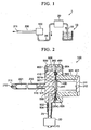
FIG. 2 is a cross-sectional view of a configuration of a pulse generation section of the first embodiment of the invention; -
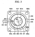
FIG. 3 is a plan view of an inlet flow passage of the first embodiment of the invention; -
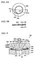
FIG. 4 is a plan view of a swiri flow generation plate of a second embodiment of the invention; -
FIG. 5 is a cross-sectional view of the pulse generation section in which the swirl flow generation plate is assembled of the second embodiment of the invention; -
FIG. 6 is a plan view of a diaphragm connected to the swirl flow generation plate of a third embodiment of the invention; -
FIG. 7 is a cross-section view taken along the line A-A shown inFIG. 6 ; -
FIG. 8A is a plan view showing the connected state of the reinforcing plate and the swirl flow generation plate of a fourth embodiment of the invention; -
FIG. 8B is a cross-sectional view taken along the line B-B shown inFIG. 8A ; -
FIG. 9 is a cross-sectional view of the pulse generation section of the fourth embodiment of the invention; -
FIG. 10 is a cross-sectional view of the pulse generation section of a fifth embodiment of the invention taken along the line C-C shown inFIG. 11 ; and -
FIG. 11 is a plan view showing the condition of the upper case related to the fifth embodiment of the invention observed from the lower case side. - The fluid injection device according to embodiments of the invention may be used for dissecting or cutting out biopsy tissue.
- Consequently, the fluid used in the embodiment is water or saline solution.
-
FIG. 1 is an explanatory schematic diagram of the configuration of the fluid injection device related to the first embodiment of the invention. - In
FIG. 1 , the fluid injection device 1 includes afluid container 10 containing the fluid as the basic configuration, apump 20 as the pressure generation section, and apulse generation section 100 generating a pulse flow of the fluid supplied from thepump 20. - A slender tubular shaped connection flow passage tube 1200 is connected to the
pulse generation section 100. - A
nozzle 211 with its flow passage compressed is inserted in the front end of the connectionflow passage tube 200. - The flow of the fluid in the fluid injection device 1 is described below in a simple manner.
- The fluid contained in the
fluid container 10 is drawn in by thepump 20 through aconnection tube 15, and is supplied to thepulse generation section 100 at constant pressure through aconnection tube 25. - As shown in
FIG. 2 , thepulse generation section 100 includes afluid chamber 501, and a volume varying section of thisfluid chamber 501. Thepulse generation section 100 drives the volume varying section and generates pulses, and injects the fluid at high speed through the connectionflow passage tube 200 and thenozzle 211. - Detailed explanations on the
pulse generation section 100 are given later referring toFIGS. 2 and3 . - The pressure generation section is not limited to pump 20; a liquid transport bag maintained at a position higher than the
pulse generation section 100 by a stand or the like may be used. - Accordingly, the advantages are: the
pump 20 is not necessary, the configuration becomes simpler, and disinfection is easy. - The discharge pressure of the
pump 20 is set at lower than or equal to 0.3 atmosphere (0.03 MPa). - If the liquid transport bag is used, the difference in height of the liquid upper surface of the
pulse generation section 100 and the liquid transport bag becomes the pressure. - If the liquid transport bag is used, it is preferable that the difference in height be set such that the pressure is in the range of 0.1 to 0.15 atmosphere (0.01 to 0.15 MPa).
- When performing surgery using the fluid injection device 1, the surgeon grasps the
pulse generation section 100. - Consequently, it is preferable that the
connection tube 25 from thepump 20 to thepulse generation section 100 be as flexible as possible. - For this reason, it is preferable that the tube be flexible and thin, and the fluid in the
pulse generation section 100 be at low pressure within the pumpable range. - Also, when a fault in the equipment may lead to a major accident, as in brain surgery, the discharge of fluid at high pressure due to a cut in the
connection tube 25 must be avoided; for this reason also, the fluid must be at low pressure. - Next, the construction of the
pulse generation section 100 according to the first embodiment is described here. -
FIG. 2 is a cross-sectional view of the configuration of thepulse generation section 100 of the first embodiment. - As shown
FIG. 2 , thepulse generation section 100 includes a pulse generating device for generating pulse in the fluid. The connectionflow passage tube 200 having a connection flow passage (first connection flow passage) 201 for discharging fluid is connected to thepulse generation section 100. - The
pulse generation section 100 is joined at the surfaces opposite to anupper case 500 and alower case 301 respectively. Theupper case 500 and thelower case 301 are screwed in with four securing screws 600 (not shown in the drawings). - The
lower case 301 is a cylindrical member having a collar. A portion of thelower case 301 opposite to theupper case 500 is sealed by thebase plate 311. - A
piezoelectric element 401 is disposed in the space within thelower case 301. - The
piezoelectric element 401 is a stacked-type piezoelectric element and constitutes an actuator. - The first end of the
piezoelectric element 401 is fixed todiaphragm 400 throughupper plate 411, and the second end of thepiezoelectric element 401 is fixed to theupper surface 312 of thebase plate 311. - Also, the
diaphragm 400 is made of a disc-shaped thin metallic plate. The peripheral edge in thegroove 303 of thelower case 301 is fixed in intimate contact with the bottom surface of thegroove 303. - When a drive signal is input to the
piezoelectric element 401 used as the volume varying section, the volume of thefluid chamber 501 changes through thediaphragm 400 with the extension and shrinkage of thepiezoelectric element 401. - A reinforcing
plate 410 made of disc-shaped thin metallic plate having an opening at the center is stacked and disposed on the upper surface of thediaphragm 400. - A groove is formed at the central part of the surface of the
upper case 500 opposite to thelower case 301. Afluid chamber 501 in the shape of a rotating body and filled with fluid is made of this groove and thediaphragm 400. - That is, the
fluid chamber 501 includes a space enclosed by the sealingsurface 505 of the groove of theupper case 500, the innerperipheral wall 501a, and thediaphragm 400. - An outlet
flow passage tube 510 is formed to protrude from the end face of theupper case 500 opposite to thelower case 301. - An
outlet flow passage 511 is formed at substantially the center of thefluid chamber 501. - The
outlet flow passage 511 is a through passage from thefluid chamber 501 to the end of the outletflow passage tube 510. - The connection between the sealing
surface 505 and theoutlet flow passage 511 is smoothly rounded to reduce the fluid resistance. - As shown
FIG. 2 , thefluid chamber 501 described above in the first embodiment has a substantially cylindrical and sealed shape at the two ends, but when viewed from the side, the surface has no limitation. As the shape, conical, trapezoidal or hemispherical may be adopted. - For example, if the connection between the
outlet flow passage 511 and the sealingsurface 505 is made in the shape of a funnel, air bubbles in thefluid chamber 501 mentioned later, can be easily removed. - A connection
flow passage tube 200 is connected to theoutlet flow passage 510. - A
connection flow passage 201 is formed in the connectionflow passage tube 200. The diameter of theconnection flow passage 201 is grater than the diameter of theoutlet flow passage 511. - The thickness of the tubing portion of the connection
flow passage tube 200 is kept within a range such that the connectionflow passage tube 200 has adequate rigidity yet does not absorb the pressure pulses of the fluid. - A
nozzle 211 attached by insertion to the front end of the connectionflow passage tube 200. - A fluid injection opening 212 is formed in this
nozzle 211. Thus, the fluid injection opening 212 is formed at the end portion of theconnection flow passage 201. - The diameter of the fluid injection opening 212 is smaller than the diameter of the
connection flow passage 201. - An inlet
flow passage tube 502 is formed to protrude from the side face of theupper case 500. The inletflow passage tube 502 is inserted into theconnection tube 25. The inletflow passage tube 502 supplies fluid from thepump 20. - A connection flow passage (second connection flow passage) 504 is formed on the side of the inlet flow passage in the inlet
flow passage tube 502. - An
inlet flow passage 503 is connected with theconnection flow passage 504. - The
inlet flow passage 503 is formed in a groove shape in the peripheral edge of the sealingsurface 505 of thefluid chamber 501, and is connected with thefluid chamber 501. - At a position which is separated from the
diaphragm 400 in the circumferential direction, and on the connection surface between theupper case 500 and thelower case 301, apacking box 304 is formed on the side of thelower case 301 and apacking box 506 is formed on the side of theupper case 500, and a ring-shapedpacking 450 is attached in the space formed by the packingboxes - When assembling the
upper case 500 and thelower case 301, the peripheral edge of thediaphragm 400 and the peripheral edge of the reinforcingplate 410 are brought into close contact by the bottom surface of thegroove 303 of thelower case 301 and the peripheral edge of the sealingsurface 505 of theupper case 500. - In this case, the packing 450 is pressed by the
upper case 500 and thelower case 301, and fluid leakage from thefluid chamber 501 is prevented. - When the pressure inside the
fluid chamber 501 increases to a high pressure above 30 atmospheres (3 MPa) when fluid is discharged, a small amount of fluid could leak in the connections of thediaphragm 400, reinforcingplate 410,upper case 500,lower case 301, respectively, but this leak is prevented by the packing 450. - When packing 450 is disposed as shown in
FIG. 2 , the pressure of fluid that leaks at high pressure from thefluid chamber 501 compresses the packing 450, and the walls in thepacking box - As a result, the rise in high pressure in the
fluid chamber 501 can be maintained during the operation. - Next, the
inlet flow passage 503 formed in theupper case 500 is described in further detail referring to the drawings. -
FIG. 3 is a plan view of theinlet flow passage 503, and indicates the state when theupper case 500 is viewed from the side of the connecting face with thelower case 301. - The
inlet flow passage 503 inFIG. 3 is formed in the shape of a peripheral edge groove of the sealingsurface 505 of theupper case 500. - The
inlet flow passage 503 connects with thefluid chamber 501 at the first end of theinlet flow passage 503. Theinlet flow passage 503 connects with theconnection flow passage 504 at the second end of theinlet flow passage 503. - A
fluid basin 507 is formed at the connection between theinlet flow passage 503 and theconnection flow passage 504. - The fluid resistance is reduced by smoothly rounding the connection between the
fluid basin 507 and theinlet flow passage 503. - The
inlet flow passage 503 is connected with thefluid chamber 501 in the substantially tangential direction to the innerperipheral wall 501a of thefluid chamber 501. - As shown in
FIG. 1 , the fluid supplied at constant pressure from thepump 20 flows along the innerperipheral wall 501a (direction shown by arrow inFIG. 3 ), and generates a swirl flow in thefluid chamber 501. - The swirl flow presses against the side of the inner
peripheral wall 501 a due to centrifugal force because of the swirling motion, and the air bubbles included in thefluid chamber 501 concentrate at the center of the swirl flow. - The air bubbles that have collected at the center are removed from the
outlet flow passage 511. - Thus, it is preferable that the
outlet flow passage 511 be installed near the center of the swirl flow. It is preferable that theoutlet flow passage 511 be installed at the center of the axis of the rotating shape body. - Consequently, the
inlet flow passage 503 is a swirl flow generation section in the first embodiment. - In
FIG. 3 , theinlet flow passage 503 is curved in a plane form. - The
inlet flow passage 503 may be connected thefluid chamber 501 in a straight line. In order to obtain the desired inertance in a narrow space, theinlet flow passage 503 is curved. Because it is necessary to make the flow passage length of theinlet flow passage 503 long. - As shown in
FIG. 2 , a reinforcingplate 410 is disposed between thediaphragm 400 and the peripheral edge of the sealingsurface 505 in which theinlet flow passage 503 is formed. - The reinforcing
plate 410 is installed to enhance the durability of thediaphragm 400. - Since a
connection opening 509 is formed in notch shape in the connection between theinlet flow passage 503 and thefluid chamber 501, stress concentration occurs near theconnection opening 509 and fatigue failure may occur, when thediaphragm 400 is driven at a high frequency. - Therefore, a reinforcing
plate 410 with a continuous opening and no notch is disposed so that stress concentration does not occur in thediaphragm 400. -
Screw holes 500a are formed at four locations at the corners of the outer periphery of theupper case 500. Theupper case 500 and thelower case 301 are screwed together and connected at these screw hole positions. - The reinforcing
plate 410 and thediaphragm 400 may be connected and may be stacked fixed together to form an integral body, although this arrangement is not shown in the drawings. - As fixing structure, adhesive may be used to attach the items, or solid state diffusion bonding, welding or the like may be used. It is preferable that the reinforcing
plate 410 and thediaphragm 400 be in close contact at the connecting face. - Next, the operation of the first embodiment is described here referring to
FIGS. 1 to 3 . - The fluid discharge of the
pulse generation section 100 of the first embodiment is performed according to the difference between the inertance L1 (synthesized inertance L1 may sometimes be called) on the inlet flow passage side and the inertance L2 on the outlet flow passage side (synthesized inertance L2 may sometimes be called). - Inertance is first described below.
- The inertance L may be expressed by L = ρ × h/S, where density of fluid is p, cross-sectional area of flow passage is S, and the length of the flow passage is h.
- If the differential pressure in the flow passage is taken as ΔP, and the flow rate of fluid flowing in the flow passage as Q, then the equation of motion in the flow passage using inertance L may be modified to obtain the relationship ΔP=L × dQ/dt.
- That is, the inertance L indicates the influence level on the change with time of flow rate. The greater the inertance L, the smaller is the change with time of the flow rate; the smaller the inertance L, the greater is the change with time of the flow rate.
- The synthesized inertance related to parallel connections of a plurality of flow passages or direct connections of a plurality of flow passages with varying shapes can be calculated by combining the inertance of individual flow passages, similar to parallel connections or direct connections of inductance in an electric circuit.
- For the inertance L1 on the inlet flow passage side, since the diameter of the
connection flow passage 504 is set adequately greater than that of theinlet flow passage 503, the inertance L1 can be calculated in the range of theinlet flow passage 503. - In this case, since the connection tube connecting the
pump 20 and the inlet flow passage has flexibility, the connection tube may not be considered in the calculation of inertance L1. - In case of the inertance L2 on the outlet flow passage side, the diameter of the
connection flow passage 201 is much greater than the outlet flow passage, and the thickness of the tube portion (tube wall) of the connectionflow passage tube 200 is small, therefore the influence on the inertance L2 is negligible. - Consequently, the inertance L2 on the outlet flow passage side may be replaced with the inertance of the
outlet flow passage 511. - The thickness of the tube wall of the connection
flow passage tube 200 is such that it has adequate rigidity to transmit the fluid pressure. - In the first embodiment, the length and cross-sectional area of the flow passage of the
inlet flow passage 503, and the length and cross-sectional area of the flow passage of theoutlet flow passage 511 are set such that the inertance L1 on the side of the inlet flow passage becomes greater than the inertance L2 on the side of the outlet flow passage. - Next, the operation of the
pulse generation section 100 is described here. - Fluid is supplied at constant pressure at all times in the
inlet flow passage 503 by thepump 20. - As the result, when the
piezoelectric element 401 does not operate, the fluid flows into thefluid chamber 501 because of the difference in the value of the fluid resistance of the entire inlet flow passage and the discharge pressure of thepump 20. - Here, if the drive signal is input to the
piezoelectric element 401, and if thepiezoelectric element 401 extends rapidly, the pressure in thefluid chamber 501 rises sharply and reaches several tens of atmospheres if the inertance L1 and L2 on the side of the inlet flow passage and outlet flow passage are adequately high. - This pressure is much higher than the pressure due to pump 20 applied on the
inlet flow passage 503. Thus, the inflow of fluid to thefluid chamber 501 from the side of the inlet flow passage reduces according to this pressure, and the outflow from theoutlet flow passage 511 increases. - Consequently, a check valve installed on the inlet flow passage side, as in the fluid injection device according to the Japanese Unexamined Patent Application, First Publication No.
2005-152127 - However, inertance L1 of the
inlet flow passage 503 is greater than the inertance L2 of theoutlet flow passage 511; therefore, the increase in fluid discharged from the outlet flow passage is greater than the decrease in the inflow of the fluid to thefluid chamber 501 from theinlet flow passage 503. So the flow discharge in pulse form is generated to theconnection flow passage 201, that is a pulsed flow is generated. - The pressure variation at the time of this discharge is transmitted to within the connection
flow passage tube 200; that is, fluid is injected from the fluid injection opening 212 of thenozzle 211 at the front end. - Here, since the diameter of the fluid injection opening 212 of the
nozzle 211 is smaller than the diameter of theoutlet flow passage 511, the fluid is injected at a higher pressure as high speed droplets in pulse form. - On the other hand, the
fluid chamber 501 is in a vacuum state immediately after rise in pressure because of the mutual interaction between the reduction in fluid inflow rate from theinlet flow passage 503 and the increase in fluid outflow from theoutlet flow passage 511. - As the result, after a fixed period of time, the fluid in the
inlet flow passage 503 returns to the flow toward thefluid chamber 501 at the same speed as before the action of thepiezoelectric element 401 because of both pressure of thepump 20 and the vacuum state within thefluid chamber 501. - If the
piezoelectric element 401 extends after the flow of fluid in theinlet flow passage 503 is restored, the pulse flow from thenozzle 211 can be continued and fluid can be injected. - Next, the action of removal of air bubbles in the
fluid chamber 501 is described here. - During the operation of the
pulse generation section 100 described above, swirl flow occurs in thefluid chamber 501, and the air bubbles included in the fluid are discharged outside theoutlet flow passage 511 immediately. Because thefluid chamber 501 has a substantial rotating body shape and includes theinlet flow passage 503 as a swirl flow generation section, and also because theoutlet flow passage 511 is formed in an open condition near the rotating axis of the substantial rotating body shape. - Accordingly, even during a very small volume change in the
fluid chamber 501 due to thepiezoelectric element 401, pressure variation is not hindered by air bubbles, and adequate rise in pressure can be obtained. - Consequently, according to the first embodiment 1, the initial operation can be started without priming operation because fluid is supplied to the
inlet flow passage 503 at constant pressure from thepump 20 and because fluid is supplied to theinlet flow passage 503 and thefluid chamber 501 even when the drive of thepulse generation section 100 is in the stopped state. - Moreover, the liquid pressure increases above that in the
outlet flow passage 511 since fluid is discharged from the fluid injection opening 212, which is smaller than the diameter of theoutlet flow passage 511; therefore, high speed fluid injection can be attained. - Furthermore, the connection
flow passage tube 200 possesses adequate rigidity to transmit the pulses of the fluid flowing from thefluid chamber 501 to thefluid injection opening 212. Thus, the pressure propagation of fluid from thepulse generation section 100 is not hindered, and the desired pulse flow can be injected. - Since the inertance of the
inlet flow passage 503 is set greater than the inertance of theoutlet flow passage 511, an increase occurs in theoutlet flow passage 511 in the outflow rate that is greater than the decrease in the inflow rate of the fluid to thefluid chamber 501 from theinlet flow passage 503, and fluid in pulse state can be discharged into the connectionflow passage tube 200. - Therefore, advantageous effects can be obtained such as: a check valve need not be installed on the side of the
inlet flow passage 503 as in the Japanese Unexamined Patent Application, First Publication No.2005-152127 pulse generation section 100 can be simplified, internal parts can be cleaned easily, and the concern about durability when using a check valve is eliminated. - By setting the inertance of both the
inlet flow passage 503 and theoutlet flow passage 511 adequately great, and by abruptly reducing the volume of thefluid chamber 501, the pressure in thefluid chamber 501 can be increased steeply. - The construction can also be simplified by using
piezoelectric element 401 anddiaphragm 400 as the volume varying section, which can result in further miniaturization of the device. - The maximum frequency of for volume change of the
fluid chamber 501 can be made greater than or equal to 1 kHz, which is ideal for injection at high speed pulse flow. - By generating swirl flow in the fluid in the
fluid chamber 501 by the swirl flow generation section, the fluid presses against the fluid chamber in the circumferential direction because of the centrifugal force of the fluid, and the air bubbles included in the fluid near the axis of the substantial rotating body shape become concentrated at the central part of the swirl flow, and these air bubbles can be removed from theoutlet flow passage 511 formed at a portion which is closer to the axis of the substantial rotating body shape. - As a result, the reduction in pressure amplitude due to accumulation of air bubbles in the
fluid chamber 501 can be prevented, and stable operation of thepulse generation section 100 can be continued. - Moreover, since the swirl flow generation section is formed by the
inlet flow passage 503, swirl flow can be generated without using a special swirl flow generation section. - Also, a groove-shaped
inlet flow passage 503 is formed on the peripheral edge of the sealingsurface 505 of thefluid chamber 501, aninlet flow passage 503 can be formed as the swirl flow generation section without increasing the number of parts. - Moreover, since a reinforcing
plate 410 is formed on the upper surface of thediaphragm 400, and since the diaphragm is driven taking the periphery of the opening of the reinforcingplate 410 as the support point, stress concentration does not occur easily, and the durability of thediaphragm 400 can be enhanced. - If the corners of the joining surface of the reinforcing
plate 410 and thediaphragm 400 are rounded, the stress concentration of thediaphragm 400 can be further relaxed. - If the reinforcing
plate 410 and thediaphragm 400 are stacked and fixed as an integral body, the assembly of thepulse generation section 100 can be improved, and the reinforcement of the peripheral edge of thediaphragm 400 can also be made more effective. - The influence of the inertance of the
connection flow passage 504 on theinlet flow passage 503 can be suppressed by providingfluid basin 507 for collecting the fluid at the connection of theinlet flow passage 503 and theconnection flow passage 504 on the inlet side supplying fluid from thepump 20. - Moreover, since a ring-shaped
packing 450 is separately disposed at a position in the circumferential direction of thediaphragm 400 on the connection surface between theupper case 500 and thelower case 301, the leakage of fluid from thefluid chamber 501 is prevented, and the pressure drop in thefluid chamber 501 can also be prevented. - Next, the pulse generation section related to the second embodiment of the invention is described here referring to the drawings of the same.
- The second embodiment has a swirl flow generation plate including the inner peripheral wall of a fluid chamber and inlet flow passage as the swirl flow generation section.
- Other than the swirl flow generation section, the construction is similar to that of the first embodiment described above, so the explanations are omitted here. The same reference numerals as in the first embodiment are attached to the functional members that are the same in the first embodiment.
-
FIG. 4 is a plan view of the swirlflow generation plate 550, andFIG. 5 is a cross-sectional view of thepulse generation section 100 in which the swirlflow generation plate 550 is assembled. - In
FIG. 4 , the swirlflow generation plate 550 has an opening formed at its central part; however, the peripheral part of this opening has the innerperipheral wall 551 a of thefluid chamber 551 formed therein. - Also, the
inlet flow passage 558 is formed as the swirl flow generation section in thefluid chamber 551, and afluid basin 557 is formed in the part connecting theconnection flow passage 504 on the inlet side. - The shape of the
inlet flow passage 558,fluid basin 557 and innerperipheral wall 551a conform to the shape of theinlet flow passage 503, thefluid basin 507, and the innerperipheral wall 501a (seeFIG. 3 ) described in the first embodiment above. - The swirl flow
generation plate 550 may be formed by processing methods such as pressing process, etching process, or electric discharging process. - As shown in
FIG. 5 , the swirlflow generation plate 550 is stacked and disposed on the upper surface of thediaphragm 400, and is pressed and brought into contact with the peripheral face of the sealingsurface 505 of theupper case 500 and thelower case 301. - Consequently, according to second embodiment mentioned above, by forming the swirl flow generation section by the swirl
flow generation plate 550, theinlet flow passage 558, the innerperipheral wall 551 a and thefluid basin 557 can be formed by the same manufacturing process; thus, the mutual positional accuracy can be enhanced. - Also, the swirl
flow generation plate 550 is a single body, and can be formed by the pressing process, etching process or electric discharge process. The manufacturing method may be arbitrarily selected to suit the desired size such as flow passage length, width, thickness, and other shape conditions. - Moreover, if a swirl flow generation plate having cross-sectional area of inlet flow passage and flow passage length of a plurality of types of passages are available and by selecting swirl flow generation plate, the desired inertance of the inlet flow passage can be easily selected.
- Next, the third embodiment of the invention is described here referring to the drawings.
- The third embodiment has a swirl flow generation plate and diaphragm stacked and attached in intimate contact as an integral body.
- Other than the swirl flow generation section, the construction is similar to that of the second embodiment described above, so the explanations are omitted here. The same reference numerals as in the second embodiment are attached to the functional members that are the same in the second embodiment also.
-
FIG. 6 is a plan view of the swirlflow generation plate 550 and theconnected diaphragm 400 related to the third embodiment.FIG. 7 is a cross-section view taken along the line A-A shown inFIG. 6 . - The swirl flow
generation plate 550 is attached in intimate contact as an integral body with thediaphragm 400 inFIGS. 6 and 7 . - The swirl flow
generation plate 550 and thediaphragm 400 may be attached to each other by attaching structure such as bonding using adhesive, by solid state diffusion bonding, welding or the like. It is preferable that the swirlflow generation plate 550 and thediaphragm 400 be in close contact at the connecting face. - According to this third embodiment, the swirl
flow generation plate 550 is made from a thin plate. An opening that forms the innerperipheral wall 551 a of thefluid chamber 551 and theinlet flow passage 558 is provided. - Slender peninsular-shaped members are formed in the
connection 559 at which the opening and theinlet flow passage 558 are connected. - Since the high pressure state and the vacuum state occur repetitively in the
fluid chamber 551, the structural strength of the slender peninsular-shaped members mentioned above may be inadequate. - However, adequate structural strength can be obtained by integrating the
diaphragm 400 and the swirlflow generation plate 550. - Another advantage is that handling is easy during assembly.
- Next, the fourth embodiment of the invention is described here referring to the drawings.
- In the fourth embodiment, an additional reinforcing plate is formed to further strengthen the structure of the second embodiment mentioned above.
- Other than the additional reinforcing plate in the swirl flow generation section, the construction is similar to that of the second embodiment described above, so the explanations are omitted here. The same reference numerals as in the second embodiment are attached to the functional members that are the same in the second embodiment also.
-
FIG. 8A is a plan view of the connected state between the swirlflow generation plate 550 and the reinforcingplate 410 related to the fourth embodiment. -
FIG. 8B is a cross-sectional view taken along the line B-B shown inFIG. 8A . - In
FIG. 8A and 8B , the swirlflow generation plate 550 has a similar shape as that in the second and third embodiments. The reinforcingplate 410 has a similar shape as that in the first embodiment. Both members are stacked, and are attached in intimate contact with each other as an integral body by fixing structure such as an adhesive, solid state diffusion bonding, welding or the like at the connecting face. - The swirl flow
generation plate 550 and the reinforcingplate 410 is assembled in thepulse generation section 100 in the attached and intimate contact state. -
FIG. 9 is a cross-sectional view of the assembled state of the joined swirlflow generation plate 550 and the reinforcingplate 410 in thepulse generation section 100. - In
FIG. 9 , the swirlflow generation plate 550 and the reinforcingplate 410 are disposed in the integrated state on the upper surface of thediaphragm 400. - Also, the swirl
flow generation plate 550 and the reinforcingplate 410 are pressed and brought into contact with the peripheral face of the sealingsurface 505 of theupper case 500 and thelower case 301. - After preparing plate members that constitute the swirl
flow generation plate 550 and the reinforcingplate 410, the plate member constituting the swirlflow generation plate 550 is joined to the plate member constituting the reinforcingplate 410, and theinlet flow passage 558,fluid basin 557 and innerperipheral wall 551 of the swirlflow generation plate 550 may be formed by half-etching, and the innerperipheral wall 410a of the reinforcingplate 410 may be formed by etching. - Even if the
diaphragm 400 and reinforcingplate 410 are joined, and the swirlflow generation plate 550 is assembled and constructed as a single structure, thediaphragm 400, the reinforcingplate 410 and the swirlflow generation plate 550 may be stacked, and attached in intimate contact with each other. - Consequently, according to the fourth embodiment mentioned above, by stacking and attaching the swirl
flow generation plate 550 and the reinforcingplate 410 in intimate contact with each other to form an integral body, the swirlflow generation plate 550 can be reinforced, and handling during assembly also becomes easy. - Also, by stacking and attaching the
diaphragm 400 and the reinforcingplate 410 as an integral body, or by stacking and attaching thediaphragm 400, the reinforcingplate 410 and the swirlflow generation plate 550 in intimate contact with each other, the effects of the embodiments of the invention mentioned above work well. - Next, the pulse generating device related to the fifth embodiment of the invention is described here referring to the drawings of the same.
- According to the fifth embodiment, the inlet flow passage is formed by tubular member that penetrates the fluid chamber and an exterior of the pulse generation section. The construction of the inlet flow passage is mainly described here.
- With respect to other functional members, the same reference numerals as in the first embodiment are affixed and described here.
-
FIG. 10 is a cross-sectional view of thepulse generation section 100 related to the fifth embodiment taken along the line C-C shown inFIG. 11 , whileFIG. 11 is a plan view of theupper case 500 as viewed from the side of thelower case 301. - In
FIGS. 10 and 11 , the inletflow passage tube 520 is to attach by insertion into theupper case 500 toward thefluid chamber 501. - The inlet
flow passage tube 520 is made from a metallic tubular member, penetrates the outside of theupper case 500, and passes through up to thefluid chamber 501. - Accordingly, the
inlet flow passage 521 formed in the inletflow passage tube 520 connects with thefluid chamber 501. - When the
inlet flow passage 521 is configured with the same conditions for thepulse generation section 100 and the inertance L1 of the inlet side shown in the first embodiment above, the cross-sectional area and the flow passage length are set the same as for theinlet flow passage 503 as shown inFIG. 3 . - Here, the construction of attachment by insertion of the inlet
flow passage tube 520 is described. - An insertion hole guide portion for inlet
flow passage tube 514 is formed in theupper case 500 into which the inletflow passage tube 520 is attached by insertion. - Inlet flow passage tube insertion holes 512 and 513 are formed in a substantially perpendicular direction from the surface of this insertion hole guide portion for inlet
flow passage tube 514 toward thefluid chamber 501. - Low-melting point silver solder plating is provided on the inlet
flow passage tube 520. After insertion in the inlet flow passagetube insertion hole 513, it is heated and fused by the silver solder. The inletflow passage tube 520 and theupper case 500 are attached in intimate contact with each other, and the leakage of fluid from thefluid chamber 501 is prevented. - The front end of the inlet
flow passage tube 520 is cut such that it does not protrude into thefluid chamber 501. - The method of attaching the inlet
flow passage tube 520 may be selected from using adhesive, by press-fitting or the like. A method that can resist the pressure in thefluid chamber 501 and that does not generate leakage of fluid is preferable. - The
fluid chamber 501 includes a groove formed at the connection of thelower case 301 with theupper case 500. Thefluid chamber 501 has a substantial rotating body shape. - The
inlet flow passage 503 is installed in a substantially tangential direction with respect to the innerperipheral wall 501 a of thefluid chamber 501 as shown inFIG. 11 . - Accordingly, a swirl flow can be generated in the
fluid chamber 501. - A
connection tube 25 connecting the pump 20 (seeFIG. 1 ) is connected to the end in the outward direction of the inletflow passage tube 520. - The
end 25a of theconnection tube 25 extends up to the inside of the inlet flow passagetube insertion hole 512. To minimize the clearance to the radial direction of theend 25a and the inlet flow passagetube insertion hole 512, the inletflow passage tube 520 can be reinforced - Although not illustrated, if the part of the inlet
flow passage tube 520 protruding outside theupper case 500 is bent, the direction of connection of theconnection tube 25 can be set arbitrarily, and the operability of thepulse generation section 100 can be improved. - Consequently, according to the fifth embodiment described above, if the
inlet flow passage 521 is formed by the inletflow passage tube 520, the cross-sectional shape of theinlet flow passage 521 can be made circular, and the resistance elements in the flow passage can be reduced. - Also, the cross-sectional area and the length of the tubular member can be easily set. Also, if various types of tubular members are kept ready beforehand, the cross-sectional area and the flow passage length of the
inlet flow passage 521 can be easily set to match the settings of inertance on the side of theinlet flow passage 521. - The claimed invention is not limited to the embodiments mentioned above; changes and modifications within the scope of the claimed invention are included.
- Consequently, according to the first to the fifth embodiments described above, in the fluid injection device, a priming device (priming operation) is not necessary, performance degradation due to air accumulating in the fluid chamber during the operation is eliminated, and a simple construction with no check valve and with high reliability can be offered.
Claims (3)
- A biological tissue incising device for injecting fluid to biological tissue, comprising:a fluid chamber (501, 551),an inlet flow passage (503, 521, 558) and an outlet flow passage (511) that are connected to the fluid chamber;a connection flow passage (201) configured to be connected to the outlet flow passage, having a fluid injection opening (212) with a diameter smaller than the diameter of the outlet flow passage; anda pressure generation section (20) configured to supply fluid to the inlet flow passage,characterised in that an inertance of the inlet flow passage is set greater than an inertance of the outlet flow passage.
- The biological tissue incising device according to claim 1, further comprising:a volume varying section (400, 401) configured to vary a volume of the fluid chamber, the volume varying section including a piezoelectric element configured to expand or compress the fluid chamber; anda diaphragm (400).
- The biological tissue incising device according to claim 2, further comprising a ring-shaped packing (450) separately disposed at a position in a circumferential direction of the diaphragm (400).
Applications Claiming Priority (2)
| Application Number | Priority Date | Filing Date | Title |
|---|---|---|---|
| JP2006261114A JP5082049B2 (en) | 2006-09-26 | 2006-09-26 | Fluid ejecting apparatus and surgical tool |
| EP07018804.0A EP1905590B1 (en) | 2006-09-26 | 2007-09-25 | Fluid injection device |
Related Parent Applications (1)
| Application Number | Title | Priority Date | Filing Date |
|---|---|---|---|
| EP07018804.0A Division EP1905590B1 (en) | 2006-09-26 | 2007-09-25 | Fluid injection device |
Publications (2)
| Publication Number | Publication Date |
|---|---|
| EP2772357A1 EP2772357A1 (en) | 2014-09-03 |
| EP2772357B1 true EP2772357B1 (en) | 2015-08-12 |
Family
ID=38804263
Family Applications (2)
| Application Number | Title | Priority Date | Filing Date |
|---|---|---|---|
| EP14163529.2A Active EP2772357B1 (en) | 2006-09-26 | 2007-09-25 | Fluid injection device |
| EP07018804.0A Active EP1905590B1 (en) | 2006-09-26 | 2007-09-25 | Fluid injection device |
Family Applications After (1)
| Application Number | Title | Priority Date | Filing Date |
|---|---|---|---|
| EP07018804.0A Active EP1905590B1 (en) | 2006-09-26 | 2007-09-25 | Fluid injection device |
Country Status (3)
| Country | Link |
|---|---|
| US (5) | US7901374B2 (en) |
| EP (2) | EP2772357B1 (en) |
| JP (1) | JP5082049B2 (en) |
Families Citing this family (80)
| Publication number | Priority date | Publication date | Assignee | Title |
|---|---|---|---|---|
| JP4311483B2 (en) * | 2007-08-10 | 2009-08-12 | セイコーエプソン株式会社 | Liquid ejecting apparatus and surgical instrument using the same |
| JP5050982B2 (en) * | 2008-04-24 | 2012-10-17 | セイコーエプソン株式会社 | Fluid ejection device and surgical scalpel |
| JP2010051430A (en) * | 2008-08-27 | 2010-03-11 | Seiko Epson Corp | Pulse generating mechanism, connection flow channel tube, fluid ejection apparatus |
| JP2010057531A (en) * | 2008-09-01 | 2010-03-18 | Seiko Epson Corp | Fluid jetting apparatus, method of controlling the same and surgical apparatus |
| JP2010059792A (en) * | 2008-09-01 | 2010-03-18 | Seiko Epson Corp | Fluid injection device, fluid injection unit, control device, method of controlling fluid injection device and operating device |
| JP5277802B2 (en) * | 2008-09-05 | 2013-08-28 | セイコーエプソン株式会社 | Fluid ejection device and surgical scalpel |
| JP5293031B2 (en) | 2008-09-16 | 2013-09-18 | セイコーエプソン株式会社 | Fluid ejecting apparatus and surgical instrument |
| JP4752892B2 (en) * | 2008-09-30 | 2011-08-17 | セイコーエプソン株式会社 | Fluid ejecting apparatus and surgical instrument |
| JP5267020B2 (en) * | 2008-09-30 | 2013-08-21 | セイコーエプソン株式会社 | Fluid ejecting apparatus, driving method of fluid ejecting apparatus, and surgical instrument |
| JP2010082306A (en) | 2008-10-01 | 2010-04-15 | Seiko Epson Corp | Fluid ejection device, driving method for fluid ejection device, and operating instrument |
| JP4666094B2 (en) | 2009-07-10 | 2011-04-06 | セイコーエプソン株式会社 | PULSE FLOW GENERATION DEVICE, MEDICAL DEVICE, AND METHOD OF CONTROLLING PULSE FLOW GENERATION DEVICE |
| JP4952754B2 (en) * | 2009-08-12 | 2012-06-13 | セイコーエプソン株式会社 | Liquid ejecting apparatus, scalpel for operation, and method for controlling liquid ejecting apparatus |
| JP4788809B2 (en) * | 2009-08-17 | 2011-10-05 | セイコーエプソン株式会社 | Fluid injection method |
| JP4655163B1 (en) | 2009-08-26 | 2011-03-23 | セイコーエプソン株式会社 | Fluid ejecting apparatus and method for controlling fluid ejecting apparatus |
| JP5573064B2 (en) * | 2009-09-17 | 2014-08-20 | アイシン精機株式会社 | Human body local cleaning equipment |
| JP5360690B2 (en) * | 2009-09-25 | 2013-12-04 | セイコーエプソン株式会社 | Fluid ejecting apparatus and method for controlling fluid ejecting apparatus |
| JP5509766B2 (en) * | 2009-09-25 | 2014-06-04 | セイコーエプソン株式会社 | Fluid ejection device and treatment device |
| JP2011143145A (en) * | 2010-01-18 | 2011-07-28 | Seiko Epson Corp | Liquid-jet device |
| JP5540760B2 (en) | 2010-02-22 | 2014-07-02 | セイコーエプソン株式会社 | Liquid ejector |
| JP2011177330A (en) | 2010-03-01 | 2011-09-15 | Seiko Epson Corp | Excision device and air-bubble detecting method |
| JP2011177407A (en) | 2010-03-03 | 2011-09-15 | Seiko Epson Corp | Fluid injection device |
| JP5609194B2 (en) | 2010-03-23 | 2014-10-22 | セイコーエプソン株式会社 | Liquid ejector |
| JP5636811B2 (en) * | 2010-08-20 | 2014-12-10 | セイコーエプソン株式会社 | Liquid ejecting apparatus and medical device using liquid ejecting apparatus |
| JP5565464B2 (en) * | 2010-08-20 | 2014-08-06 | 株式会社村田製作所 | Stop valve, fuel cell system |
| JP5614170B2 (en) | 2010-08-23 | 2014-10-29 | セイコーエプソン株式会社 | Liquid ejecting apparatus and surgical instrument using the liquid ejecting apparatus |
| JP5212440B2 (en) * | 2010-09-03 | 2013-06-19 | セイコーエプソン株式会社 | Laser pulse scalpel and medical equipment |
| JP5549489B2 (en) * | 2010-09-06 | 2014-07-16 | セイコーエプソン株式会社 | Fluid injection method |
| JP5803354B2 (en) * | 2010-10-08 | 2015-11-04 | セイコーエプソン株式会社 | Fluid ejecting apparatus and medical device |
| JP5585369B2 (en) * | 2010-10-12 | 2014-09-10 | セイコーエプソン株式会社 | Fluid ejecting apparatus and medical device |
| JP5083399B2 (en) * | 2010-10-25 | 2012-11-28 | セイコーエプソン株式会社 | Fluid ejecting apparatus and surgical instrument |
| US8794931B2 (en) * | 2010-12-24 | 2014-08-05 | Seiko Epson Corporation | Fluid ejection device and medical device |
| JP5870565B2 (en) * | 2011-09-08 | 2016-03-01 | セイコーエプソン株式会社 | Liquid ejector |
| JP5668485B2 (en) * | 2011-01-18 | 2015-02-12 | セイコーエプソン株式会社 | Liquid container, liquid ejecting section, and liquid ejecting apparatus |
| CN102602142B (en) * | 2011-01-18 | 2016-03-02 | 精工爱普生株式会社 | Liquid injection apparatus |
| JP5862020B2 (en) | 2011-02-28 | 2016-02-16 | セイコーエプソン株式会社 | Fluid ejection device |
| JP5742317B2 (en) | 2011-03-11 | 2015-07-01 | セイコーエプソン株式会社 | Fluid ejection device |
| JP5776246B2 (en) * | 2011-03-22 | 2015-09-09 | セイコーエプソン株式会社 | Liquid ejector |
| CN102734140B (en) * | 2011-04-12 | 2016-03-09 | 深圳市华简泵业科技有限公司 | Piezoelectric pump and its pipe arrangement |
| JP5776447B2 (en) | 2011-08-30 | 2015-09-09 | セイコーエプソン株式会社 | Control device and excision device used in connection with fluid ejection device for excising biological tissue by ejected fluid |
| US9243619B2 (en) | 2011-09-13 | 2016-01-26 | Seiko Epson Corporation | Liquid feed pump and circulation pump with detection units to detect operating states of the pumps |
| JP2014005755A (en) * | 2012-06-22 | 2014-01-16 | Seiko Epson Corp | Liquid feeding pump and circulating device |
| JP5903816B2 (en) * | 2011-09-16 | 2016-04-13 | セイコーエプソン株式会社 | Control device for pulsation generator and liquid ejecting apparatus |
| JP5845798B2 (en) | 2011-10-17 | 2016-01-20 | セイコーエプソン株式会社 | Control device, liquid ejecting apparatus, medical device and program |
| JP5286476B2 (en) | 2011-12-08 | 2013-09-11 | 株式会社メトラン | Pump unit, breathing assistance device |
| JP5874503B2 (en) | 2012-02-17 | 2016-03-02 | セイコーエプソン株式会社 | Liquid ejector system and medical device |
| JP5636555B2 (en) * | 2012-04-02 | 2014-12-10 | 株式会社メトラン | Pump unit, breathing assistance device |
| CN103417265A (en) | 2012-05-15 | 2013-12-04 | 精工爱普生株式会社 | Medical apparatus |
| JP5408324B2 (en) * | 2012-10-15 | 2014-02-05 | セイコーエプソン株式会社 | Fluid ejecting apparatus and medical device |
| US9746506B2 (en) | 2012-12-18 | 2017-08-29 | Nucleus Scientific Inc. | Nonlinear system identification for optimization of wireless power transfer |
| JP6186798B2 (en) | 2013-03-28 | 2017-08-30 | セイコーエプソン株式会社 | Fluid ejecting apparatus and medical device |
| JP2014188240A (en) | 2013-03-28 | 2014-10-06 | Seiko Epson Corp | Fluid jetting device, and medical equipment |
| JP6229286B2 (en) | 2013-03-29 | 2017-11-15 | セイコーエプソン株式会社 | Liquid ejector, medical equipment |
| JP2014206088A (en) * | 2013-04-12 | 2014-10-30 | セイコーエプソン株式会社 | Liquid injection device and medical equipment |
| JP5682654B2 (en) * | 2013-05-07 | 2015-03-11 | セイコーエプソン株式会社 | Fluid ejecting apparatus and surgical instrument |
| EP2804151B1 (en) | 2013-05-16 | 2020-01-08 | Hexagon Technology Center GmbH | Method for rendering data of a three-dimensional surface |
| JP2014013040A (en) * | 2013-07-17 | 2014-01-23 | Seiko Epson Corp | Fluid jetting device, fluid jetting surgical instrument and fluid jetting method |
| JP2015033508A (en) | 2013-08-09 | 2015-02-19 | セイコーエプソン株式会社 | Medical instrument holding apparatus |
| JP2015058169A (en) | 2013-09-19 | 2015-03-30 | セイコーエプソン株式会社 | Liquid jet device and medical equipment |
| JP2015058234A (en) * | 2013-09-20 | 2015-03-30 | セイコーエプソン株式会社 | Medical liquid injection device |
| JP2015058233A (en) * | 2013-09-20 | 2015-03-30 | セイコーエプソン株式会社 | Medical liquid injection device |
| JP5737365B2 (en) * | 2013-11-08 | 2015-06-17 | セイコーエプソン株式会社 | Fluid ejection device and surgical scalpel |
| JP5800042B2 (en) * | 2014-01-30 | 2015-10-28 | セイコーエプソン株式会社 | Fluid ejecting apparatus and surgical instrument |
| JP6264550B2 (en) * | 2014-03-04 | 2018-01-24 | セイコーエプソン株式会社 | Channel member, liquid ejecting head, and liquid ejecting apparatus |
| JP5907203B2 (en) * | 2014-04-03 | 2016-04-26 | セイコーエプソン株式会社 | Nozzle part for fluid ejecting mechanism, fluid ejecting apparatus, and surgical apparatus |
| JP2015198762A (en) | 2014-04-08 | 2015-11-12 | セイコーエプソン株式会社 | Fluid injection device |
| JP2015198861A (en) * | 2014-04-10 | 2015-11-12 | セイコーエプソン株式会社 | Fluid injection device, and fluid injection method |
| JP2014223313A (en) * | 2014-05-19 | 2014-12-04 | セイコーエプソン株式会社 | Nozzle part for fluid jet mechanism, fluid jet device, and surgical device |
| JP2016000067A (en) | 2014-06-11 | 2016-01-07 | セイコーエプソン株式会社 | Cellular tissue transecting method, and liquid injection device |
| JP5924385B2 (en) * | 2014-09-02 | 2016-05-25 | セイコーエプソン株式会社 | Control device and liquid ejecting apparatus |
| JP2015037607A (en) * | 2014-10-29 | 2015-02-26 | セイコーエプソン株式会社 | Nozzle unit for fluid ejection device, piezoelectric element unit for fluid ejection device, fluid ejection device, and surgical scalpel |
| JP2016176457A (en) * | 2015-03-23 | 2016-10-06 | セイコーエプソン株式会社 | Actuator unit for liquid injection device and hand piece for liquid injection device |
| JP6015805B2 (en) * | 2015-04-21 | 2016-10-26 | セイコーエプソン株式会社 | Drive control device |
| DE102016206902A1 (en) * | 2016-04-22 | 2017-10-26 | Technische Universität Bergakademie Freiberg | Device for modulating at least one liquid jet |
| JP6222322B2 (en) * | 2016-09-26 | 2017-11-01 | セイコーエプソン株式会社 | Medical equipment |
| JP2018103139A (en) * | 2016-12-28 | 2018-07-05 | セイコーエプソン株式会社 | Fluid discharge device |
| CN108266367A (en) * | 2016-12-30 | 2018-07-10 | 亚申科技研发中心(上海)有限公司 | Fluid delivery system |
| CN106885120B (en) * | 2017-03-21 | 2018-09-07 | 哈尔滨工业大学 | A kind of micro injection lubricating arrangement of diaphragm seal formula Piezoelectric Driving |
| CN107246377B (en) * | 2017-06-20 | 2019-04-30 | 江苏大学 | A kind of unidirectional vortex tube structure Valveless piezoelectric pump and control method |
| US10531883B1 (en) | 2018-07-20 | 2020-01-14 | Syntheon 2.0, LLC | Aspiration thrombectomy system and methods for thrombus removal with aspiration catheter |
| JP2022000338A (en) * | 2020-06-17 | 2022-01-04 | セイコーエプソン株式会社 | Flow channel member, liquid jetting head, liquid jetting device, and method for manufacturing flow channel member |
Family Cites Families (25)
| Publication number | Priority date | Publication date | Assignee | Title |
|---|---|---|---|---|
| US3810465A (en) * | 1971-01-27 | 1974-05-14 | J Lambert | Pulsating syringe |
| US4727378A (en) * | 1986-07-11 | 1988-02-23 | Tektronix, Inc. | Method and apparatus for purging an ink jet head |
| JPS63176679A (en) | 1987-01-17 | 1988-07-20 | Fuji Electric Co Ltd | Piezo-electric pump |
| WO1988010192A1 (en) * | 1987-06-25 | 1988-12-29 | Siemens Aktiengesellschaft | Ink printing head with tangential-feed pressure chambers |
| EP0407517B1 (en) | 1988-12-29 | 1995-08-09 | Chang, Ann Lois | Diaphragm pump |
| US5591184A (en) * | 1994-10-13 | 1997-01-07 | Sentinel Medical, Inc. | Fluid jet surgical cutting instrument |
| US5591344A (en) * | 1995-02-13 | 1997-01-07 | Aksys, Ltd. | Hot water disinfection of dialysis machines, including the extracorporeal circuit thereof |
| IE960927A1 (en) * | 1996-12-31 | 1998-07-01 | Elan Med Tech | A device for generating a pulsatile fluid drug flow |
| JPH11107925A (en) * | 1997-10-08 | 1999-04-20 | Nissan Motor Co Ltd | Bellows pump |
| WO1999061191A1 (en) * | 1998-05-28 | 1999-12-02 | Mitsubishi Denki Kabushiki Kaisha | Wire electric discharge machine |
| JP2000145649A (en) | 1998-11-13 | 2000-05-26 | Sugino Mach Ltd | Fluid jetting device |
| JP3761754B2 (en) * | 1999-11-29 | 2006-03-29 | 日本ピラー工業株式会社 | Fluid equipment such as pumps and accumulators |
| JP2002130135A (en) * | 2000-10-26 | 2002-05-09 | Matsushita Electric Ind Co Ltd | Diaphragm and pump device therewith |
| JP3757173B2 (en) * | 2002-02-18 | 2006-03-22 | 旭サナック株式会社 | Diaphragm pump |
| US7094040B2 (en) * | 2002-03-27 | 2006-08-22 | Minolta Co., Ltd. | Fluid transferring system and micropump suitable therefor |
| US6899290B2 (en) * | 2002-06-24 | 2005-05-31 | Delphi Technologies, Inc. | Fuel swirler plate for a fuel injector |
| JP2004116327A (en) * | 2002-09-25 | 2004-04-15 | Fuji Electric Holdings Co Ltd | Microdispenser |
| JP2004162547A (en) * | 2002-11-11 | 2004-06-10 | Seiko Epson Corp | Pump |
| JP2004180841A (en) | 2002-12-02 | 2004-07-02 | Univ Waseda | Blood pump unit |
| JP4266788B2 (en) * | 2003-11-21 | 2009-05-20 | セイコーエプソン株式会社 | Fluid ejection device |
| JP4479306B2 (en) * | 2004-03-30 | 2010-06-09 | セイコーエプソン株式会社 | pump |
| JP2005307743A (en) * | 2004-04-16 | 2005-11-04 | Seiko Epson Corp | Pump priming device |
| JP4346562B2 (en) * | 2005-01-28 | 2009-10-21 | 東レエンジニアリング株式会社 | Liquid transfer pump |
| JP4677933B2 (en) * | 2005-04-14 | 2011-04-27 | セイコーエプソン株式会社 | Pump and fluid system |
| JP4355722B2 (en) * | 2005-11-17 | 2009-11-04 | セイコーエプソン株式会社 | Fluid transport device |
-
2006
- 2006-09-26 JP JP2006261114A patent/JP5082049B2/en active Active
-
2007
- 2007-09-25 US US11/902,766 patent/US7901374B2/en active Active
- 2007-09-25 EP EP14163529.2A patent/EP2772357B1/en active Active
- 2007-09-25 EP EP07018804.0A patent/EP1905590B1/en active Active
-
2011
- 2011-02-02 US US13/019,575 patent/US8337452B2/en active Active
-
2012
- 2012-11-13 US US13/675,640 patent/US8652091B2/en active Active
-
2014
- 2014-02-14 US US14/180,875 patent/US9073069B2/en active Active
-
2015
- 2015-06-04 US US14/730,850 patent/US9555423B2/en active Active
Also Published As
| Publication number | Publication date |
|---|---|
| US20140163417A1 (en) | 2014-06-12 |
| JP2008082202A (en) | 2008-04-10 |
| US7901374B2 (en) | 2011-03-08 |
| US9555423B2 (en) | 2017-01-31 |
| EP1905590A2 (en) | 2008-04-02 |
| US20130079707A1 (en) | 2013-03-28 |
| US9073069B2 (en) | 2015-07-07 |
| EP1905590A3 (en) | 2013-03-27 |
| US20110125086A1 (en) | 2011-05-26 |
| US20080086077A1 (en) | 2008-04-10 |
| US8337452B2 (en) | 2012-12-25 |
| US20150266035A1 (en) | 2015-09-24 |
| EP1905590B1 (en) | 2014-04-09 |
| EP2772357A1 (en) | 2014-09-03 |
| JP5082049B2 (en) | 2012-11-28 |
| US8652091B2 (en) | 2014-02-18 |
Similar Documents
| Publication | Publication Date | Title |
|---|---|---|
| EP2772357B1 (en) | Fluid injection device | |
| US8857734B2 (en) | Fluid injection device | |
| EP2022418B1 (en) | Fluid jet device | |
| US20100054960A1 (en) | Pulsation generating mechanism, connecting flow channel tube, and fluid ejecting apparatus | |
| CN102648866B (en) | Operation device | |
| JP2010084564A (en) | Fluid injection device, method for controlling fluid injection device, and surgical appliance | |
| JP5320906B2 (en) | Fluid ejection surgical instrument and fluid ejection method | |
| JP5277802B2 (en) | Fluid ejection device and surgical scalpel | |
| JP2010059792A (en) | Fluid injection device, fluid injection unit, control device, method of controlling fluid injection device and operating device | |
| JP2009299690A (en) | Pulse generator and fluid injection device | |
| JP2010051896A (en) | Fluid jetting device, fluid jetting surgical device, and fluid jetting method | |
| JP2010059939A (en) | Fluid injection device, method of controlling fluid injection device, and surgical device | |
| JP2011193949A (en) | Fluid injection apparatus | |
| JP5782763B2 (en) | Fluid ejection device | |
| JP2013056016A (en) | Liquid ejecting apparatus | |
| JP2010084566A (en) | Fluid ejection device and surgical appliance | |
| JP2013163044A (en) | Fluid jet device and surgical scalpel | |
| JP2015037607A (en) | Nozzle unit for fluid ejection device, piezoelectric element unit for fluid ejection device, fluid ejection device, and surgical scalpel | |
| JP2013056014A (en) | Liquid ejecting apparatus | |
| JP2012152265A (en) | Liquid ejecting apparatus |
Legal Events
| Date | Code | Title | Description |
|---|---|---|---|
| PUAI | Public reference made under article 153(3) epc to a published international application that has entered the european phase |
Free format text: ORIGINAL CODE: 0009012 |
|
| 17P | Request for examination filed |
Effective date: 20140404 |
|
| AC | Divisional application: reference to earlier application |
Ref document number: 1905590 Country of ref document: EP Kind code of ref document: P |
|
| AK | Designated contracting states |
Kind code of ref document: A1 Designated state(s): DE FR GB |
|
| RIN1 | Information on inventor provided before grant (corrected) |
Inventor name: TAKAYAMA, KAZUYOSHI Inventor name: HOSSEINT, SEYED HAMID REZA Inventor name: SETO, TAKESHI Inventor name: KAWASUMI, KAZUO |
|
| R17P | Request for examination filed (corrected) |
Effective date: 20150107 |
|
| RBV | Designated contracting states (corrected) |
Designated state(s): DE FR GB |
|
| GRAP | Despatch of communication of intention to grant a patent |
Free format text: ORIGINAL CODE: EPIDOSNIGR1 |
|
| RIC1 | Information provided on ipc code assigned before grant |
Ipc: B41J 2/03 20060101AFI20150216BHEP Ipc: A61B 17/3203 20060101ALI20150216BHEP Ipc: B41J 2/19 20060101ALI20150216BHEP |
|
| INTG | Intention to grant announced |
Effective date: 20150309 |
|
| RIN1 | Information on inventor provided before grant (corrected) |
Inventor name: SETO, TAKESHI Inventor name: KAWASUMI, KAZUO Inventor name: TAKAYAMA, KAZUYOSHI Inventor name: HOSSEINI, SEYED HAMID REZA |
|
| GRAS | Grant fee paid |
Free format text: ORIGINAL CODE: EPIDOSNIGR3 |
|
| GRAA | (expected) grant |
Free format text: ORIGINAL CODE: 0009210 |
|
| AC | Divisional application: reference to earlier application |
Ref document number: 1905590 Country of ref document: EP Kind code of ref document: P |
|
| AK | Designated contracting states |
Kind code of ref document: B1 Designated state(s): DE FR GB |
|
| REG | Reference to a national code |
Ref country code: GB Ref legal event code: FG4D |
|
| REG | Reference to a national code |
Ref country code: DE Ref legal event code: R096 Ref document number: 602007042623 Country of ref document: DE |
|
| REG | Reference to a national code |
Ref country code: DE Ref legal event code: R097 Ref document number: 602007042623 Country of ref document: DE |
|
| PLBE | No opposition filed within time limit |
Free format text: ORIGINAL CODE: 0009261 |
|
| STAA | Information on the status of an ep patent application or granted ep patent |
Free format text: STATUS: NO OPPOSITION FILED WITHIN TIME LIMIT |
|
| 26N | No opposition filed |
Effective date: 20160513 |
|
| REG | Reference to a national code |
Ref country code: FR Ref legal event code: PLFP Year of fee payment: 10 |
|
| REG | Reference to a national code |
Ref country code: FR Ref legal event code: PLFP Year of fee payment: 11 |
|
| REG | Reference to a national code |
Ref country code: FR Ref legal event code: PLFP Year of fee payment: 12 |
|
| PGFP | Annual fee paid to national office [announced via postgrant information from national office to epo] |
Ref country code: GB Payment date: 20230803 Year of fee payment: 17 |
|
| PGFP | Annual fee paid to national office [announced via postgrant information from national office to epo] |
Ref country code: FR Payment date: 20230808 Year of fee payment: 17 Ref country code: DE Payment date: 20230802 Year of fee payment: 17 |