EP2772074B1 - Systeme und verfahren zur dynamischen stummschaltung in funkfrequenzvorrichtungen - Google Patents
Systeme und verfahren zur dynamischen stummschaltung in funkfrequenzvorrichtungen Download PDFInfo
- Publication number
- EP2772074B1 EP2772074B1 EP12844451.0A EP12844451A EP2772074B1 EP 2772074 B1 EP2772074 B1 EP 2772074B1 EP 12844451 A EP12844451 A EP 12844451A EP 2772074 B1 EP2772074 B1 EP 2772074B1
- Authority
- EP
- European Patent Office
- Prior art keywords
- hailing
- channel
- data
- channels
- noise floor
- Prior art date
- Legal status (The legal status is an assumption and is not a legal conclusion. Google has not performed a legal analysis and makes no representation as to the accuracy of the status listed.)
- Not-in-force
Links
Images


Classifications
-
- H—ELECTRICITY
- H04—ELECTRIC COMMUNICATION TECHNIQUE
- H04W—WIRELESS COMMUNICATION NETWORKS
- H04W24/00—Supervisory, monitoring or testing arrangements
- H04W24/04—Arrangements for maintaining operational condition
-
- H—ELECTRICITY
- H04—ELECTRIC COMMUNICATION TECHNIQUE
- H04W—WIRELESS COMMUNICATION NETWORKS
- H04W56/00—Synchronisation arrangements
- H04W56/001—Synchronization between nodes
-
- H—ELECTRICITY
- H04—ELECTRIC COMMUNICATION TECHNIQUE
- H04B—TRANSMISSION
- H04B17/00—Monitoring; Testing
- H04B17/30—Monitoring; Testing of propagation channels
- H04B17/309—Measuring or estimating channel quality parameters
- H04B17/318—Received signal strength
-
- H—ELECTRICITY
- H04—ELECTRIC COMMUNICATION TECHNIQUE
- H04W—WIRELESS COMMUNICATION NETWORKS
- H04W16/00—Network planning, e.g. coverage or traffic planning tools; Network deployment, e.g. resource partitioning or cells structures
- H04W16/24—Cell structures
- H04W16/32—Hierarchical cell structures
-
- H—ELECTRICITY
- H04—ELECTRIC COMMUNICATION TECHNIQUE
- H04W—WIRELESS COMMUNICATION NETWORKS
- H04W4/00—Services specially adapted for wireless communication networks; Facilities therefor
- H04W4/70—Services for machine-to-machine communication [M2M] or machine type communication [MTC]
-
- H—ELECTRICITY
- H04—ELECTRIC COMMUNICATION TECHNIQUE
- H04B—TRANSMISSION
- H04B17/00—Monitoring; Testing
- H04B17/30—Monitoring; Testing of propagation channels
- H04B17/309—Measuring or estimating channel quality parameters
- H04B17/345—Interference values
Definitions
- the present disclosure generally relates to the operation of radio frequency devices, and more particularly relates to synchronizing data communications between radio frequency devices.
- utility meters e.g., gas meters, water meters, and electricity meters
- Manual meter reading represents a significant cost to a typical utility provider.
- utility providers have sought methods and systems for remote reading of water meters and/or remote control of water supply valves.
- Advanced Metering Infrastructure or Advanced Metering Management
- AMI Advanced Metering Infrastructure
- AMM Advanced Metering Management
- the advanced metering devices combine internal data measurements with continuously available remote communications, enabling the metering devices to transmit and receive data through the AMI network.
- an advanced metering device such as an advanced water meter, measures and collects usage data, such as water usage data, at a customer's location.
- the metering device uses a built-in communication interface to transmit data to a parent node up the network, often in response to the parent's request for such information. In this way, utility providers may remotely "read" customer usage data for billing purposes.
- An exemplary method includes: listening for a first hailing signal to be received on at least one hailing channel selected from a plurality of hailing channels, selecting at least one hailing channel based upon a system time and a node identification; determining a noise floor for the at least one hailing channel; and upon receiving a noise signal on the at least one hailing channel, adjusting the noise floor in response to the noise signal.
- the present disclosure describes systems and methods for operating radio frequency (RF) devices such as Advanced Metering Infrastructure devices (AMI) using frequency-hopping spread spectrum technology. More particularly, the systems and methods disclosed herein relate to time-based hailing of radio frequency devices.
- RF radio frequency
- AMI Advanced Metering Infrastructure devices
- FHSS frequency-hopping spread spectrum
- the advanced metering devices Because of the remote placement nature of the advanced metering devices, it is desired to maximize battery life of the metering devices in order to reduce down time and to reduce the amount of maintenance that must be performed on the metering devices. Similarly, it is desired to maximize responsiveness in communications between the advanced metering devices and the utility provider network while complying with FCC rules and regulations. It is also desired to reduce interference and background noise that may cause communication failures and that may further decrease battery life of the advanced meters.
- a MASTER state device As used herein, a MASTER state device, a device in MASTER state, or a master device is a device that is attempting to send data to another device.
- a SLAVE state device, a device in SLAVE state, a slave device, or a target device is a device to which the master is attempting to send data.
- “parent” and “child” nodes should not be confused with “MASTER state” and "SLAVE state” devices.
- MASTER state and SLAVE state are merely states/modes for each device.
- a child node such as devices 112, 114, 116 in FIG. 1 is further up the hierarchy in relation to the utility provider 102 than a child node such as devices 112, 114, 116 in FIG. 1 ).
- a child node such as devices 112, 114, 116 in FIG. 1
- a single parent may be paired with a single child.
- child nodes may represent individual customers' utility meters while a parent node may represent a primary data collection device responsible for collecting date from and sending data to each child device. This configuration requires that the parent device's system time be highly accurate.
- Utility companies must periodically determine customer usage by taking meter readings. To facilitate this process and to reduce costs to the utility companies, utility meters in the present disclosure may transmit usage data wirelessly through a network, such as a mesh network, back to the utility provider. To reduce costs further while increasing reliability, it is an object of the present disclosure to increase battery life while increasing data transmission reliability and reducing system response times. To do this, each of the utility company's AMI RF devices is in one of 3 states: SLEEP state used to conserve battery life; SLAVE state used for responding to and receiving data from a MASTER state device; and MASTER state used to initiate communications with ( i.e., "hail") and send data to a SLAVE state device.
- SLEEP state used to conserve battery life
- SLAVE state used for responding to and receiving data from a MASTER state device
- MASTER state used to initiate communications with (i.e., "hail" and send data to a SLAVE state device.
- SLEEP state In SLEEP state, a device partially awakens and briefly listens for a "hailing" signal on a hailing channel from another device in MASTER state. If the device in SLEEP state fails to detect a hailing signal, the device remains in SLEEP state and periodically partially awakens to listen for a hailing signal.
- the SLEEP state device changes hailing channels based on a predefined pseudorandom hailing channel frequency set dependent upon a system time. Once the SLEEP state device is "hailed" by a MASTER state device, it fully awakens and begins listening for data messages from the MASTER state device on a predefined data channel selected from the predefined pseudorandom data channel frequency set, the data channel being indicated by the MASTER state device. In other words, the SLEEP state device exits SLEEP state and enters SLAVE state.
- a device listens for and receives data messages on a data channel selected from the predefined pseudorandom data channel frequency set.
- the MASTER state device indicates which data channel to use by sending a data channel pointer to the target device during the hailing process.
- the SLAVE state device After receiving each message from the MASTER state device, the SLAVE state device sends an acknowledgement (ACK) message to the MASTER state device, indicating a successfully received data message.
- ACK acknowledgement
- the SLAVE state device and the MASTER state device then switch to the next data channel in the data channel frequency set and continue communications until all data messages have been sent.
- a device In MASTER state, a device "hails" a SLEEP state device by sending a hailing signal on a hailing channel to the targeted SLEEP state device.
- the MASTER state device selects which hailing channel to use based on: 1) the SLEEP state device's predefined pseudorandom hailing channel frequency set, 2) a system time corresponding to the hailing channel frequency set, and 3) a unique serial number (the "nodeID") of the SLAVE state device.
- the system time on the MASTER state device and the system time on the SLAVE state device are substantially in synchronization.
- the MASTER state device Upon successfully "hailing" the sleeping device (which upon hailing becomes a SLAVE state device), the MASTER state device begins sending data messages on a data channel to the SLAVE state device.
- the data channel is selected from the SLAVE state device's predefined pseudorandom data channel set based on the system time.
- the data channel frequency set is common to the MASTER state device and the SLAVE state device.
- the MASTER state device may indicate to the SLAVE state device during the hailing procedure what the next available data channel is by sending to the SLAVE state device a data channel pointer.
- Hailing channels and data channels are selected from the 902-928 MHz industrial, scientific, and medical (ISM) bandwidth.
- ISM industrial, scientific, and medical
- one hundred (100) channels are chosen with a minimum channel spacing of 100 kHz each.
- Fifty (50) of the channels are randomly assigned to the pseudorandom data channel frequency set, and fifty (50) different channels are randomly assigned to the hailing channel frequency set.
- the set of fifty (50) hailing channels are used during the MASTER and SLEEP states to send and receive hailing requests while the set of fifty (50) data channels are used during the MASTER and SLAVE states to send and receive data messages.
- a particular radio frequency device selects an initial subset of two (2) consecutive channels (i.e ., a channel group) from its predefined pseudorandom hailing channel frequency set to be used while in the SLEEP state (by first calculating a channel offset based on its unique assigned serial number (the "nodeID")). This offset is added to a hailing channel pointer.
- the hailing channel pointer points to one of the fifty (50) available hailing channels, and increments to the next set of two (2) channels every, for example, 18 seconds so that each device will continuously "hop" through all of the fifty (50) available hailing channels at a system hopping rate. In this manner, hailing channel usage is spread across the predefined hailing channel.
- the hailing channel usage may be substantially equal manner such that each channel within the hailing channel frequency set is used for substantially the same amount of time or for substantially the same number of times. In one embodiment, the hailing channel usage might be skewed to use hailing channels with less interference more frequently while using hailing channels with more interference less frequently.
- the devices hop through the data channel frequency set to assure that, on average, all data channels are used equally.
- the present disclosure utilizes two pseudorandom frequency sets: a predefined pseudorandom hailing channel frequency set and a predefined pseudorandom data channel frequency set.
- Hailing channels and data channels are randomly selected from the 902-928 MHz ISM radio bandwidth.
- one hundred (100) channels are chosen having a minimum channel spacing of 100 kHz each.
- Fifty (50) of the channels are randomly assigned to the hailing channel frequency set, and fifty (50) different channels are randomly assigned to the data channel frequency set.
- a different number of total channels, a different number of hailing channels, and/or a different number of data channels may be used.
- the data channels and the hailing channels are mutually exclusive (i.e., every data channel is different from every hailing channel).
- a subset of the data channels and the hailing channels may be the same, while other data channels and other hailing channels may be different.
- the set of data channels and hailing channels may be the same.
- the channel spacing may be greater or less than the 100 kHz spacing discussed above.
- a non-limiting, exemplary set of 50 hailing channels includes the following frequencies: Ch. Freq. Ch. Freq. Ch. Freq. Ch. Freq. 0 926.8 MHz 1 922.96 MHz 2 925.48 MHz 3 922.72 MHz 4 922 MHz 5 925.96 MHz 6 922.84 MHz 7 922.48 MHz 8 923.32 MHz 9 925 MHz 10 923.2 MHz 11 924.52 MHz 12 925.12 MHz 13 922.6 MHz 14 923.68 MHz 15 925.36 MHz 16 924.16 MHz 17 927.76 MHz 18 927.88 MHz 19 927.4 MHz 20 924.76 MHz 21 924.28 MHz 22 926.92 MHz 23 926.44 MHz 24 927.16 MHz 25 922.63 MHz 26 924.04 MHz 27 923.92 MHz 28 923.56 MHz 29 923.08
- these hailing channels may be grouped into hailing channel groups.
- hailing channel group 0 may include hailing channels 0 and 1 (908.15 MHz and 919.8 MHz in the above example), while hailing channel group 1 may include hailing channels 2 and 3 (922.65 MHz and 902.65 MHz in the above example), continuing through hailing channel group 24.
- hailing channel group “n” may include hailing channel “x” and hailing channel "x+1" where "x" represents a hailing channel.
- hailing channel groups may include a different number or combination of hailing channels.
- a non-limiting, exemplary set of 50 data channels (beginning with data channel 0 and continuing through data channel 49) includes the following frequencies: Ch. Freq. Ch. Freq. Ch. Freq. Ch. Freq. 0 922.94 MHz 1 922.1 MHz 2 923.78 MHz 3 922.46 MHz 4 926.9 MHz 5 927.26 MHz 6 922.82 MHz 7 923.3 MHz 8 927.86 MHz 9 927.5 MHz 10 923.9 MHz 11 926.42 MHz 12 925.46 MHz 13 927.38 MHz 14 926.3 MHz 15 925.7 MHz 16 925.1 MHz 17 926.18 MHz 18 925.94 MHz 19 924.02 MHz 20 927.98 MHz 21 926.66 MHz 22 924.98 MHz 23 927.62 MHz 24 924.74 MHz 25 925.22 MHz 26 925.34 MHz 27 924.62 MHz 28 924.5 MHz 29 926.54
- these data channels may be grouped into data channel groups.
- data channel group 0 may include data channels 0 and 1 (922 MHz and 904.5 MHz in the above example), while data channel group 1 may include data channels 2 and 3 (908 MHz and 925 MHz in the above example), continuing through data channel group 24.
- data channel group “p” may include data channel “y” and data channel "y+1" where "y" represents a data channel.
- data channel groups may include a different number or combination of data channels.
- the data channels are not grouped.
- the hailing channel frequency set and the data channel frequency set are unique to each device/node within the system.
- the hailing channel frequency set and the data channel frequency set may be the same or contain a portion of the same frequency channels.
- Each device/node has a "nodeID" which identifies it within the network.
- a device wishing to send a communication to a target device utilizes the target device's "nodeID” to identify the correct hailing channel frequency set and data channel frequency set to use for that particular target device.
- the "nodeID" is an identifier, such as an alphabetic and/or numeric string, associated with and unique to a device.
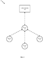
- FIG. 1 is an exemplary block diagram of the network topology of an AMI mesh network, including utility provider 102 and AMI devices including RF devices 110, 112, 114, 116.
- the RF devices discussed herein may also be referred to as "AMI devices,” “nodes,” or “devices.”
- the configuration of AMI devices shown in FIG. 1 is merely one configuration, and additional devices or alternative configurations may be used. As such, the configuration of AMI devices shown in FIG. 1 should not be seen as limiting but instead as merely exemplary.
- the dashed lines of FIG. 1 represent wireless communication links between the devices 110,112,114,116 and the utility provider 102, which may be active during some periods of time and which may not be active during other periods of time, as will become clear throughout the present disclosure.
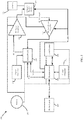
- an RF circuit 200 may be included in any of the AMI devices shown in FIG. 1 , such as RF devices 110, 112, 114, 116.
- RF circuit 200 within each RF device 110, 112, 114, 116 enables the devices to communicate wirelessly with one another.
- Battery 205 powers a transceiver integrated circuit (IC) 210, a microprocessor 220, an RF power amplifier 230, an RF low noise amplifier 240, and flash memory 250.
- Crystal oscillators 215,225 are connected to transceiver IC 210 and microprocessor 220, respectively.
- the circuit 200 includes a transmit/receive switch 260 and antenna 270.
- flash memory 250 is specified, any type of memory such as RAM, ROM, flash memory, etc. may be used with RF circuit 200, as understood by those having skill in the art.
- a data line connects antenna 270 to the transmit/receive switch 260.
- RF received data from antenna 270 is fed into RF low noise amplifier 240 and then to transceiver IC 210.
- Transceiver IC 210 is connected to microprocessor 220 and to RF power amplifier 230. If RF transmission data is to be sent to antenna 270 and, thereby, to another remotely located communicator (for example, from RF device 110 to RF device 112 of FIG. 1 ), it is transmitted to the RF power amplifier 230 where it is amplified and transmitted to transmit/receive switch 260 and on to antenna 270 for communication.
- meter data is wirelessly received and transmitted to and from a host and remotely located meter nodes connected to water meters.
- Microprocessor 220 and transceiver IC 210 include both a two-way data and a two-way control line.
- Microprocessor 220 includes a control line to each of RF low noise amplifier 240 and transmit/receive switch 260.
- Microprocessor 220 is also connected to flash memory 250 by both a two-way data line and by a battery status line, the battery line included so that flash memory 250 may notify microprocessor 220 of its power and battery status.
- microprocessor 220 is connected to a device circuit 280.
- device circuit 280 may include a utility meter such as a water meter or an electricity meter.
- device circuit 280 may be a reporting and testing device, such as a water or gas leak detection device.
- RF circuit 200 may be configured on various radio topologies in various embodiments, including point-to-point, point-to-multipoint, mesh networking, and Star, among others. RF circuit 200 may be configured to communicate in multiple topologies or in one of multiple topologies.
- RF devices such as those shown in FIG. 1 (devices 110, 112, 114, 116) and FIG. 2 may be in one of 3 states at any given time: SLEEP state used to conserve battery life; SLAVE state used for responding to and receiving data from a MASTER state device; and MASTER state used to initiate communications with (i.e., "hail") and to send data to a SLAVE state device.
- a device initiating a communication is referred to herein as the "master” or the "MASTER state device” and the device which is the target of the communication is the "target,” the “target device,” the “slave” or the "SLAVE state device.”
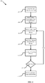
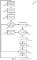
- FIG. 3 is an exemplary flow diagram 300 of the SLEEP state of an RF device.
- Some AMI devices e.g., RF devices 110, 112, 114, 116) are battery powered. To maximize the life of the device batteries, these devices are normally in SLEEP state until it is time to transmit and/or to receive data messages. In this state, the AMI device, such as RF device 112, is in a "deep sleep" (i.e ., very low power mode) and wakes up once every 0.75 seconds to listen for a hailing signal from a device in MASTER state, for example, such as RF device 110 in FIG. 1 .
- a "deep sleep" i.e ., very low power mode
- the device listens to its currently-defined hailing channel group consisting of two (2) hailing channels from the hailing channel frequency set. While a two hailing channel configuration is disclosed, single channel or other multi-channel configurations may be used. If radio frequency power (e.g., a hailing signal) is detected on one of the hailing channels, the AMI device then tries to decode a hailing message on that channel, the hailing message containing a pointer to a particular data channel (the data channel pointer). Once a device in SLEEP state has received a hailing message, the device then synchronizes with the transmitting device (i.e.
- the master through any remaining channels of the two hailing channel set and then switches to the proper data channel, as indicated by the data channel pointer.
- the SLAVE state device waits for a data channel message from the master. Once the data channel message is received, the target device responds with an acknowledgement message (ACK message) on the same channel and then switches to the next data channel in the data channel frequency set.
- ACK message acknowledgement message
- a device such as RF device 112 of FIG. 1 , which may be battery powered, enters SLEEP state upon the termination of a prior data transmission at block 302.
- the device waits for a period of time known as the "sleepTime" before proceeding to block 306.
- the AMI device listens for a hailing signal on a first hailing channel. Selection of hailing channels is discussed above in the Pseudorandom Frequency Sets section, and an exemplary hailing channel frequency set and data channel frequency set are shown.
- the present disclosure may determine whether to enter SLAVE state (enter data mode) at block 500 after listening on each hailing channel individually.
- the AMI device After listening on the first hailing channel, the AMI device then listens for a hailing signal on a second hailing channel at block 310 (and any subsequent hailing channels if more hailing channels are present in the hailing channel group). If a hailing signal is detected (block 312) on the second hailing channel, the AMI device enters SLAVE state for receiving data at block 500, as discussed below. If no hailing signal is detected (block 312) on the second hailing channel, the AMI device then prepares to enter the deep sleep during which the AMI device does not attempt to detect a hailing signal. To enter this deep sleep, the AMI device increments its wait time counter (block 314), then determines whether the total hailing time (e.g.
- sleepTime ⁇ n) is less than the total channelPeriod (block 316).
- the total channelPeriod is the amount of time the AMI device utilizes one hailing channel or group of hailing channels before moving on to the next. If so, the AMI device enters the deep sleep and waits a duration of sleepTime before attempting to detect a hailing signal again.
- the sleepTime may be approximately 750 milliseconds; however this time may be adjusted depending on the number of hailing channels used during each cycle.
- the AMI device increments its hailing channel counters at block 318 such that the first hailing channel becomes a third hailing channel and the second hailing channel becomes the fourth hailing channel, the hailing channels being determined from the hailing channel frequency set.
- the channelPeriod may be approximately 18 seconds, which would result in every hailing channel-for example, 50 hailing channels when used two-at-a-time-being used over a 7.5 minute period.
- a different channelPeriod and/or a different sleepTime may be advantageous.
- an AMI device such as RF device 112 of FIG. 1 may be a line powered device that does not need to conserve power and can therefore utilize a more aggressive channel monitoring procedure than a battery powered RF device.
- Line powered AMI devices may continuously sample all 50 of its hailing channels without waiting a sleepTime between sampling.
- the sampling method is similar to the battery operated device method shown in FIG. 3 , but sampling is continuous. That is, both methods sample the RF power in each channel.
- the unit When RF power is detected in one of the hailing channels, the unit will then try to decode a hailing message on that channel. When a hailing message is successfully decoded, it contains a data channel pointer to a particular data channel.
- the AMI device then synchronizes with the transmitter through any remaining channels of the two channel set.
- the AMI device then switches to the indicated data channel and waits for a data channel message from the master. Once the data channel message is received, the AMI device responds with an ACK message on the same channel. The device then switches to the next data channel in the data channel frequency set to continue receiving the data message.
- a target device in SLAVE state such as RF device 112 of FIG. 1 is awake after having synchronized successfully through being hailed by a device in MASTER state, discussed below, such as RF device 110 of FIG. 1 .
- the target AMI device waits for data transmission from the AMI device in MASTER state (block 404).
- the target AMI device determines which data channel selected from its data channel frequency set to use based on the data channel pointer sent during the hailing procedure by the MASTER state device.
- the SLAVE state device When data messages are received (block 406), the SLAVE state device responds to the MASTER state device by transmitting an ACK message on the same data channel (block 408) back to the MASTER state device. After sending the ACK message (block 408), the SLAVE state device switches to the next data channel in the data channel frequency set (block 410) to wait for more data from the MASTER state device (block 412). If the MASTER state device has additional data to transmit, it sends the additional data on the next data channel. The cycle continues until the MASTER state device has no more data to transmit. Once the last data message has been received and the final ACK message has been sent (or the device times out waiting for a message), the SLAVE state device will return to the SLEEP state (block 414).
- an AMI device in MASTER state such as RF device 110 of FIG. 1 is in one of two modes of operation: hailing mode for hailing and synchronizing with an AMI device in SLEEP state using the hailing channel frequency set; and data mode for transmitting data to and receiving data from a device in SLAVE state using the data channel frequency set.
- the AMI device in MASTER state uses hailing mode to synchronize communications with and to connect to the AMI device that is in SLEEP state.
- the device exits SLEEP state and enters MASTER state for synchronizing with and sending data to another AMI device.
- the MASTER state device sends a hailing message on the hailing channel(s) currently being sampled (as determined from the hailing channel frequency set, system timer, and nodeID) by the device that is in SLEEP state (block 506).
- Each hailing message contains a data channel pointer indicating which sequentially next data channel to use from the data channel frequency set. If the hailing attempt is unsuccessful (block 508), the MASTER device attempts additional hailing attempts after waiting a delay period (block 507) and retries the hailing procedure as discussed herein with particular reference to FIG. 9 .
- the MASTER state device After successfully hailing the SLEEP state device (which then enters SLAVE state) and synchronizing communications, the MASTER state device will switch to the indicated data channel (block 510) and send a data message to the target device (block 512). If an ACK message is received (block 514) from the SLAVE state device, the MASTER state device switches to the next data channel (as determined from the predefined pseudorandom data channel frequency set) and continues sending data. If no ACK message is received (block 514) by the MASTER state device from the SLAVE state device, the MASTER state device switches to the next set of hailing channels and retries hailing and synchronization (block 504). In one embodiment, the total occupancy of any channel will be less than 400 milliseconds within a 20 second period.
- the MASTER state device sends data in each of its data channels, switching channels only after receiving an ACK message from the SLAVE state device, until all data has been sent.
- the data length is variable depending on the amount of data to be transmitted.
- Each new data transmission begins on the sequentially next channel in the MASTER state device's normal data hopping sequence as determined from the data channel frequency set.
- data channel usage is therefore spread across the data channel frequency set substantially equally to minimize the channel occupancy and assure that, on average, all channels in the data channel frequency set are used substantially equally.
- both the MASTER state device and the SLAVE state device return to SLEEP state.
- scheduled communications (uploads from a MASTER state device to other devices) have a minimum random delay time added to the start of hailing of, for example, at least 7.5 minutes. The random delay time ensures that, on average, all of the hailing channels are used equally by beginning the hailing process at different channels on a random basis.
- the following describes the operating mode and settings for radio frequency enabled nodes/devices.
- the biggest drain on the projected battery life is caused by the periodic "sniffing" of hailing channels and the time spent transmitting.
- the sniffing rate on the receiving side should be balanced with the amount of hailing that needs to be sent from the transmitting side.
- an optimum system performance for minimum battery drain is a "sniffing" rate of approximately 800 milliseconds and a hailing transmission of approximately 800 milliseconds (this equates to two hail messages).
- the timers within the processor operate it may be necessary in some embodiments to reduce the sniff rate to, for example, approximately 750 milliseconds.
- other sniffing rates and/or hailing transmission times may be required depending on hardware specifications and environmental factors.
- FIG. 6 shows a graph 600 of power usage in an exemplary system of the present disclosure.
- “WoR PWR” represents the average rate of current draw in milliamps ("ma").
- the current draw occurs in periodic pulses.
- a pulse may be 10 milliamps for 10 milliseconds, and that pulse may repeat at a rate of once every 1000 milliseconds.
- the current draw between pulses may be less, for example 1 milliamp, during the 990 millisecond period between pulses.
- FIG. 6 shows the plot of the average power for the WoR, the average power used in the hailing process, and the sum of these two values.
- the optimum number of hailing channels required to minimize the average current draw on the battery may be determined.
- the number of hailing channels sniffed increases, but these channels are "sniffed” less frequently.
- “Hail PWR” represents the average milliamps used for one hailing attempt in a day. The power increases with the total number of channels used in the hailing attempt. TotalPWR is the sum of Hail PWR and WoR PWR.
- the MASTER state device and the SLEEP state device must know which hailing channels to use at any given time. As discussed, each device has a hailing channel frequency set.
- the MASTER state device selects a channel from the SLEEP state device's hailing channel frequency set based on a system time and the SLEEP state device's nodeID, which is known to the MASTER state device. That is, the MASTER state device and the SLEEP state device share a common system time, and the hailing channel to be used is selected from the hailing channel frequency dependent upon the system time.
- the system clock (“sysClock”) may be the only time reference kept by a device. By itself, the sysClock time has no meaning relative to wall clock time. Rather, it merely tracks the elapse of real time. In one embodiment, the sysClock may be in synchronization with wall clock time.
- the sysClock is a counter maintained by the firmware within each device and is based on a periodic signal generated by each devices' hardware (such as by oscillator 225 and microprocessor 220 in FIG. 2 ).
- the firmware is responsible for configuring the hardware of each device such that a periodic interrupt (the "sysTimer interrupt”) is generated, for example, every approximately 750 milliseconds in one embodiment.
- the "sysTimer interrupt may vary in frequency, as recognized by those having skill in the art.
- the sysTimer interrupt is derived from a crystal and hardware based prescaler. These crystals typically have an accuracy of 20ppm ⁇ 100ppm. However, to ensure reliability within the system, an accuracy of 5ppm or less is preferred. For this reason, a more precise value for the sysTimer interrupt may be required, although other precision levels may be advantageous depending on the particular embodiment as recognized by those of ordinary skill in the art.
- the value of the sysClock is incremented each time the sysTimer interrupt is processed. The value of the increase is determined by the firmware calibration procedures described below in the Firmware Calibration section.
- a device may contain a hardware real-time clock (RTC) chip.
- the RTC chip is not used as the wall clock reference time, but instead, the RTC chip serves as a backup to the sysClock. Since the sysClock is much more accurate than the RTC, the RTC is set from the sysClock reference at the start of each upload. If a unit with an RTC chip is reset, for example following a power failure, it then determines if the value contained in the RTC is valid and if so, the device loads its sysClock counter from the RTC chip. If the RTC chip time is not valid, then the sysClock will restart from 0.
- RTC hardware real-time clock
- the time drift between any two nodes should be, for example, approximately one second per day or less.
- Many of the current commercially available products have hardware not capable of supplying the required accuracy; therefore, a firmware calibration may be needed to alter the sysClock to achieve the desired accuracy and reliability.
- the firmware calibration process should be executed periodically to maintain the required accuracy.
- a firmware calibration may be performed by comparing a high-accuracy clock reference generated from a radio frequency temperature-compensated crystal oscillator (TCXO) (for example, crystal oscillator 225 in FIG. 2 ) with an accuracy of approximately 2ppm (known as "ref clock") to the sysClock used to produce the sysTimer.
- TCXO radio frequency temperature-compensated crystal oscillator
- the sampling time and ref clock may include: 1 ref _ clock _ freq sample _ time * 10 6 ⁇ 5 ppm where "ref_clock_freq” is the frequency of the reference clock derived from the TCXO and "sample time” is based on a number of sysTimer interrupts.
- the sysTimer interrupt is derived from the hardware crystal oscillator within the RF device (for example, crystal oscillator 225 in FIG. 2 ), its accuracy is the same as the crystal oscillator, which may be, for example, approximately 100ppm.
- the value of the sysClock is then increased by the true interrupt value each time the interrupt is processed.
- UTC Time - Coordinated Universal Time is calculated by adding a utcTimeOffSet variable to the current sysClock time.
- the utcTimeOffSet variable is stored, in one embodiment, in EPROM. As those skilled in the art recognize, other types of memory may be used.
- the value of the utcTimeOffSet is the difference between the local sysClock and the UTC time received from a device in MASTER state during the hailing procedure as described herein.
- the utcTimeOffSet variable is updated periodically (e.g., at least once per day at the start of an upload attempt).
- UTC Time is defined as timeSync plus the utcTimeOffSet:
- UTCtime sysClock + utcTimeOffSet
- Timesync - Timesync data contains a four-byte value that represents the source UTC time (e.g., which RF device sent the UTC time).
- Timesync information is always included in both a ping message (sent by the MASTER state device) and a pong ACK message (sent by the SLAVE state device).
- both the MASTER state device and the SLAVE state device exchange timesync information as part of the hailing procedure.
- Each device only uses timesync information if it is sourced from one of its "parent" nodes. Otherwise, the timesync information is discarded by the "child” node unless the child node has no parents. In this case, the received timesync information is used by the child node regardless of the source of the timesync.
- the parent node is the master clock and hailing timer source for all of its children.
- the parent must have a stable timing reference that allows only minimal timer shifts to propagate through the network via its children. This can be achieved using the same firmware calibration procedure described in the Firmware Calibration section above.
- the parent may utilize the standard simple network time protocol (SNTP) to retrieve time information from a remote data source such as the Internet. The parent may update its time once per day, for example, or on some other periodic schedule.
- SNTP simple network time protocol
- FIG. 7 is a flow diagram showing the process 700 relating to a device receiving a timesync from another device.
- the device (such as RF device 112 shown in FIG. 1 ) polls to determine whether it receives a timesync (block 702). If not, the device continues to poll (block 702). If the device does detect a received timesync at block 702, the device determines whether it has a parent device (such as RF device 110 shown in FIG. 1 ) (block 704). If the device does have a parent as determined at block 704-or multiple parents in one embodiment-the device then determines whether the timesync was sent by its parent (or one of its parents) (block 706).
- a parent device such as RF device 110 shown in FIG. 1
- the device updates its utcTimeOffSet to equal the received timesync from its parent (block 708).
- the device Upon updating its utcTimeOffSet, the device returns to polling for a new timesync (block 702).
- the device rejects the timesync and continues polling for a new timesync (block 702). If the device has no parents, however, it accepts any received timesync and updates its utcTimeOffSet to equal the received timesync (block 708).
- the device Upon updating its utcTimeOffSet, the device returns to polling for a new timesync (block 702).
- the device may not poll and instead timesync information is received via the hailing signal, which may include the timesync information.
- the AMI device verifies that the UTC time is valid first by checking to see if the oscillator stop flag ("OSF") (such as for oscillator 225 shown in FIG. 2 ) is set in the device. If the OSF is set, then the UTC time in the device is not valid. If this is the case, the device uses data from the RTC chip to recreate the sysClock and verify that the resulting UTC time calculation returns a date after the stored firmware release date.
- the present disclosure utilizes the firmware release date, which represents the date that the firmware load was released to production from the manufacturer, to verify the system time.
- the value of the RTC chip may show a time many years in the past.
- the firmware release date provides a reference date for comparing to the system clock to ensure that the new system time is reasonable. If the date is before the firmware release date then the time is invalid. If a device cannot restore a valid sysClock from an UTC device, then it may request a valid timesync from a parent device.
- the system hailing timer is a virtual timer within each RF device that operates continuously.
- the system hailing timer period is a 450 second timer; however, other timer values may be desirable as those of reasonable skill in the art can appreciate.
- the local nodeID is used to calculate the offset.
- the target SLEEP state device's nodeID is used to calculate the offset. The resulting value will point to one of the hailing channels selected from the hailing channel frequency set. This timer is common between nodes and controls the selection of both transmitting and monitoring/receiving hailing channels.
- FIG. 8 shows a diagram of an exemplary hailing sequence using a 450 second system hailing timer period.
- the hailing timer period is broken into 25 hailing channel time periods of 18 seconds each.
- the 50 hailing channels from the hailing channel frequency set are paired into 25 channel pairs.
- Each hailing channel pair is assigned to a hailing channel time (e.g., hailing channel time 0, hailing channel time 1, ... , hailing channel time 24).
- Each hailing channel time is 18 seconds long in one embodiment, meaning that a SLEEP state device will attempt to detect a hailing signal on only these two channels periodically for a period of 18 seconds.
- the hailing method is further described herein and shown, in particular, in exemplary flow diagram 300 of the SLEEP state in FIG. 3 .
- Super Sniffing Mode In one embodiment, whenever a device receives a new timesync, regardless of the source, and the resulting time shift is more than a predefined threshold, for example, 7 seconds, the device enters "super sniffing mode." During super sniffing mode, the device attempts to detect a hailing signal on all 50 of its hailing channels sequentially with no waiting period between attempts, rather than using the hailing method disclosed for SLEEP state hailing. This embodiment enables the device to apply a new timesync from its parent more quickly and prevents the device from being disconnected from its own children. This embodiment further enables faster testing and debugging of the network when a valid timesync from a parent is unavailable, for example, during maintenance.
- a predefined threshold for example, 7 seconds
- the device When the source of the time shift is a parent of the device, the device stays in super sniffing mode for an extended period, for example, 24 hours. In other cases, the device stays in super sniffing mode for a significantly shorter period, for example, 20 minutes. Upon completion of super sniffing mode, the device returns to SLEEP state and normal hailing presumes.
- a parent node such as device 110 in FIG. 1 may be responsible for hundreds or even thousands of child nodes such as devices 112, 114, 116, etc. of FIG. 1 .
- parent and “child” nodes should not be confused with “MASTER state” and “SLAVE state” devices. MASTER state and SLAVE state are merely states/modes for each device.
- Parent and "child "nodes have a predefined relationship based on hierarchy ( i.e., a parent node such as device 110 in FIG. 1 is further up the hierarchy in relation to the utility provider 102 than a child node such as devices 112, 114, 116 in FIG. 1 ).
- a single parent may be paired with a single child.
- child nodes may represent individual customers' utility meters while a parent node may represent a primary data collection device responsible for collecting date from and sending data to each child device. This configuration requires that the parent device's system time be highly accurate.
- a parent is assumed to have a more accurate time than its children.
- the parent therefore becomes a "time master" for the entire cell, the cell including the parent and each of its children, in one embodiment.
- the parent device runs the same calibration algorithm as described above on its radio as described herein.
- a device includes two processors; however, as those of reasonable skill in the art recognize, different numbers of processors may be advantageous depending upon the desired implementation.
- a first processor e.g., a "rabbit" processor
- a second processor e.g., the radio processor
- network communications between parent and child devices, such as those described herein between MASTER state, SLAVE state, and SLEEP state devices.
- the rabbit processor Upon initialization, the rabbit processor sets the radio processor's time if the rabbit processor knows the time. The rabbit processor further sets the radio processor's time once per day.
- the rabbit processor may include a double battery back-up clock which maintains time across extended power failures.
- accuracy of the rabbit processor may be limited to a 32 kHz crystal, which is approximately 20ppm ⁇ 100ppm.
- the rabbit processor may use the standard SNTP protocol, as discussed above, to retrieve time from the Internet. In another embodiment, other protocols may be used as known in the art.
- the Rabbit updates its time, for example once per hour or after a system reset. Time updates may be immediately applied or delayed.
- the rabbit system time is limited in one embodiment to shifting no more than, for example, 9 seconds after each new Internet time update unless its internal time is invalid, in which case it will apply the full time shift regardless of the time shifting limit. In this way, bad time shifting settings that would disrupt the network, for example a large shift in time such as minutes or hours, may be prevented.
- a parent may automatically push the time information (timesync) to its children when hailing, causing the children to update their time information (timesync). If the parent does not know the time, it will clear the pong timestamp in its hailing messages to notify the children not to update their clocks.
- certain parents for example, parents closer to the utility provider in the network hierarchy may have their automatic time-syncing disabled and may only be time-synced when required, not automatically.
- a hailing channel group is, for example, a set of two contiguous channels from the hailing channel set. In a configuration using 50 hailing channels, there are 25 channel groups that are non-overlapping and contiguous. For example, channels 0 & 1 represent group 0, channels 2 & 3 are group 2 and so on until the last two channels 48 & 49 are used to make group 24. Referring now to FIG.
- “hailing channel time 0" represents the hailing channel time for group 0 ( i.e., channels 0 and 1)
- “hailing channel time 1” represents the hailing channel time for group 1 ( i.e., channels 2 and 3)
- “hailing channel time 24” represents the hailing channel time for group 24 ( i.e., channels 48 and 49).
- different channel groupings such as, for example, 3 channels per group
- different numbers of total channels may be advantageous in other embodiments.
- a device in SLEEP STATE monitors each hailing channel group (monitored for an incoming hailing signal from a MASTER state device) for 18 seconds, for example.
- Each RF device determines a starting channel group based on its nodeld.
- the device Whenever the hailing timer wraps back to channel group 0 (i.e ., channels 0 and 1), the device begins monitoring its starting channel group. Each channel group is monitored for 18 seconds, for example. Upon completion of each monitoring period, the device begins monitoring the next sequential channel group (shown as "channel time" in FIG. 8 ). After the device monitors channel group 24, the device monitors channel group 0. In an embodiment having 25 channels groupings of 2 channels per group, with each channel group being monitored for 18 seconds, it takes 450 seconds (7.5 minutes) to cycle through all 25 channel groups. In embodiments with other numbers of channels and/or channel groupings or with differing amounts of monitoring time, the total time to cycle through the entire channel grouping will vary accordingly. It is therefore possible to determine which channel group a device is monitoring based on the value of the hailing timer (sysTimer).
- a device i.e ., a device in MASTER state or a master device
- the master device determines it is time to send information (i.e., a data message) to another device in the network (i.e., a target device, which is in SLEEP state)
- the master device first "hails" the desired device using the hailing method described herein. In this way, the devices achieve channel hopping alignment or become synchronized.
- the device initiating the communication is the "master” and the device which is the target of the communication is the "slave.”
- any periodic communication between nodes may have a random start delay applied to the first hailing attempt.
- the random start delay may range from 0 to 13 minutes.
- Asynchronous messages such as on-demand utility meter readings do not require additional random delay and hailing can begin immediately.
- the master device To hail a slave device, the master device first determines which hailing channel group the slave is monitoring. It does this by using the slave's nodeId to determine what the slave's starting channel group is. Next the master calculates which, for example, 18 second window the system hailing timer represents and adds that value to the slave device's starting channel group. Once the master has determined which hailing channel the slave is using, it sends its first hail attempt, which consists of one hailing message sent on each of the hailing channels in the hailing channel group. The transmission of a single hailing message occupies, for example, approximately 395 milliseconds in a two-channel-per-group configuration, so the pair of hailing messages will occupy, for example, approximately 790 milliseconds.
- This hailing attempt spans the entire sniffing window of the slave ( i.e. approximately 750 milliseconds, as discussed in the Slave State and Sleep State sections above). In this way, the slave device will always have performed a channel sniff during a hail attempt. This helps ensure that, with the exception of local interference and/or background noise, it is reasonably certain that the slave device will detect the master device's hail attempt.
- the first hailing attempt should not start in the first 2 seconds or last 2 seconds of the hailing window. This allows for a 1 to 2 second difference between devices, which can be caused by drift or delays in passing time sync information.
- the hailing message contains a pointer to the master device's next channel selected from the data channel frequency set. After sending the hailing message, the master device switches to the selected data channel and sends a synchronize (ping) message. It then waits for a response acknowledgement (ACK or pong) message from the target device. If no response is received, the master retries the hail request. In one embodiment, this retry occurs during the next 18 second hailing window using the next hailing channel group. If the slave again fails to respond, the master device may continue attempting to hail the target device.
- the master If after a predetermined number of retries (for example, 3 retries) the master still has not received an ACK from the target device, it performs a "back-off and retry" procedure described in the Hailing Back-Off and Retry section below with reference to FIG. 9 . If the master device receives an ACK message response from the target device, it first processes any timesync information, then switches to the next data channel and begins normal data communications. In one embodiment, a battery powered master device returns to the SLEEP state between each hailing attempt to conserve battery life. In an embodiment with a continuously powered master device, the master may not return to SLEEP state between each hailing attempt because no battery life conservation is necessary.
- a predetermined number of retries for example, 3 retries
- the master device may perform additional back-off and retry attempts.
- a total number of retry attempts may be set (for example, 5 retry attempts). In this case, upon reaching the total of retry attempts, the master device will cease trying to contact that target device for a period of time (for example, 24 hours).
- the master device may send an alert message with the particular target device's nodeID to the utility provider that it was unable to establish communications with that particular target device.
- an RF device has multiple parents
- the above process of hailing, hailing retries and back-off, and retries is attempted for each configured parent until either all configured parents have been tried or successful contact is established with a parent.
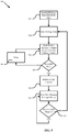
- FIG. 9 depicts a flow diagram of an exemplary embodiment of the hailing and retry process used by an RF device in MASTER state as described herein.
- the device determines whether it is time to upload data and sets its retry counter to zero. If it is not time to upload, the device continues to determine whether it is time to upload at block 902. If it is time to upload, the device determines whether it is time to perform hailing and sets the hailing counter (HailCnt) to zero (block 904). If not, the device continues polling whether it is time to perform hailing (block 904). However, if it is time to hail, the device jumps to the first hailing channel selected from the hailing channel frequency set at block 906.
- the device sends a hailing message to the target device and proceeds to the next hailing channel (block 910).
- the devices sends another hailing message to the target device and hops to the appropriate data channel selected from the hailing channel frequency set (block 914).
- the master device sends to the target device a "ping" message (block 916). If the target device successfully receives the ping message and returns an ACK ("pong") message, which is received by the master device, the master device processes any necessary timesync information, as described herein, (block 928) and then proceeds to complete the data transmission (block 930).
- the master device attempts a re-hailing of the target device if the HailCnt is less than a maximum hailing attempt value, for example, 3 hailing attempts (block 920). If the HailCnt is less than the maximum hailing attempt value, the master device waits until the next hailing time (block 922) and begins the hailing process again on the next hailing channel (block 906). However, if the HailCnt is equal to or greater than the maximum hailing attempt value, the master device will restart the entire upload attempt beginning at block 902 for a predetermined number of retry attempts (for example, 3 retry attempts) (block 924). Once the total number of retry attempts has been exceeded, the master device will wait a random delay period (for example, 2 minutes to 13 minutes as discussed above) (block 926) and begin the process again.
- a maximum hailing attempt value for example, 3 hailing attempts
- the master does not know what hailing channel or hailing channel group a slave may be sniffing at any given time.
- the master may send a hailing message on all of the hailing channels, starting with the master's next hailing channel. Due to the additional time required to send 50 hails, the hail message contains an indication so that the slave will be aware of the additional hailing.
- the master After a hailing message has been sent on all hailing channels in the hailing channel frequency set, the master hops to the indicated data channel and sends a sync request (ping) message to the slave.
- the slave responds with an ACK message (pong) on the same data channel then hops to the next data channel in the data channel frequency set to begin data communications.
- This process of "hunting" for a slave device uses a significant amount of battery power, so limiting the use of hunting as much as possible is desired. Hunting is only used for system requests and only after a set of normal hailing attempts has failed. It is also used when a particular device declares an extended outage as described below. Hunting causes one of the most significant network delays as well as causing a substantial drain on the battery life.
- each RF device maintains in memory a setting for how many days must pass without communicating with any parent after which the device enters into an extended outage mode. For example, this time period may be 10 days, although in other embodiments that duration may be shorter or longer, as persons having ordinary skill in the art can appreciate. If a device has failed to hail successfully its configured parent(s) for more than the extended outage period, it then assumes that it has lost time synchronization with its parent(s), causing the device to enter the extended outage mode.
- the device When in the extended outage mode, the device no longer attempts any automated messaging (i.e., uploads, alerts, etc.) with its parent(s). The device does continue to hunt for its primary parent once, for example, every 5 days until the device successfully hails its parent. Once this occurs, the device exits extended outage mode. Battery-powered devices that experience frequent extended communications failures also experience reduced battery life because the hunting process requires significant battery power.
- a device such as device 110 of FIG. 1 may receive an asynchronous data message (such as, for example, an installation related message or an on-demand meter read request) from a source farther up the hierarchy, for example, from utility provider 102, with instructions to relay that data message to another device, for example, device 112.
- a device attempts to forward an asynchronous relayed message, the device first performs a hailing attempt with the target device and, if unsuccessful, a hailing retry. If the target device responds to any of the hailing attempts, then the device forwards the relayed data message to the target device. Once the data message is sent to the target device and the target device sends the ACK message back to the sending device, the sending device returns to the SLEEP state.
- the sending device initiates a "hunting" attempt as described in the Hunting section above. In one embodiment, the sending device initiates the hunting attempt immediately. However, in another embodiment, the target device may wait a predetermined or random amount of time before initiating the hunting attempt. If the hunting attempt fails, the sending device returns an indication of failure (NACK) to the source of the relayed message. If a device is successful in contacting the target device, it forwards the relay message to the target device and waits for a reply (i.e., an ACK message).
- NACK indication of failure
- the target device If a device that receives a relayed message (i.e ., the target device) is unable to process the request (such as because of a low battery), the target device returns a negative acknowledgement ("NACK") message to the sending device indicating that an error has occurred and, in one embodiment, specifying the cause of the error. Otherwise, upon the successful receipt of the relayed message, the target device responds with the ACK message to the sending device and then forwards the message as necessary or process the message itself if it is the final intended target of the message.
- NACK negative acknowledgement
- the following per synchronization delays may be expected: Number of Hailing Attempts Sync Time (seconds) Min Max 1 1 4 1+1 retry 11 25 1+2 retry 29 43 1+3 retry 49 61 1+3 retry + hunt 70 81
- a parent device may be configured by an installation technician using a field radio. Since the device does not have a parent initially assigned, the device accepts and immediately applies a timesync message received from the field radio operated by a technician.
- the installed device attempts to contact its assigned parents, which may occur at preconfigured upload times. If a parent has already been installed with a valid timesync, then the installed device begins receiving and using timesync information from its parent. If the parent is not available, the installed device performs periodic attempts to contact the parent. In one embodiment, if the number of days without contacting the installed device's parent reaches the configured extended outage threshold, it begins a hunting procedure, described above in the Hunting section, for its parent. Once communication with the parent has been establish, the parent will send timesync information to the child (the installed device) and normal network communications may then follow.
- FIG. 10 depicts a block diagram of a simple network infrastructure stemming from utility provider 1010 having a plurality of nodes 1001, 1002, 1003, 1004, 1005, 1006, 1007, 1008.
- node 1001 is a parent to node 1002
- node 1002 is a parent to nodes 1003, 1004
- node 1003 is a parent to nodes 1005, 1006
- node 1004 is a parent to nodes 1007, 1008.
- the following are examples of some common actions which may be performed within a network implementing the systems and methods disclosed herein. As these are merely examples, they are not intended to be limiting. As persons of ordinary skill in the art will recognize, other configurations may be possible or otherwise advantageous.
- node 1002 has stopped functioning and needed to be replaced by a technician.
- new node 1002 When new node 1002 is placed into the network, its sysClock may not be in synchronization with the rest of the network.
- nodes 1003, 1004 it is also possible that the sysClocks of node 1002's children (nodes 1003, 1004) as well as their respective children are no longer in synchronization with one another or with node 1001.
- new node 1002 accepts timesync information from any node.
- the device can be configured from utility provider 1010 through the network or locally using a field radio. Either way it is configured, it is assumed that the timesync that the child device receives will be in synchronization with the network time and, therefore, in synchronization with the sysClock of node 1001.
- Nodes 1003 and 1004 may also need to update their parents also. In one embodiment, this could be accomplished through a system message from utility provider 1010 routed through nodes 1001 and 1002. In another embodiment, this may be accomplished through a message routed from a field radio through new node 1002. In either case, new node 1002 may perform a hunting procedure as described above to connect to its children (nodes 1003 and 1004). In the case of node 1003, as soon as the hunt is successful, node 1003 receives timesync information from node 1002, its parent. If the time shift is substantial, node 1003 enters into super sniffing mode, as disclosed herein, which enables its children (nodes 1005 and 1006) to continue to connect to it.
- node 1004 is hunted. Nodes 1005, 1006, 1007, and 1008 will all get the new timesync on their next upload. This procedure ensures that, upon completion of replacing node 1002 with new node 1002, all nodes should be able to upload virtually immediately.
- node 1002 in the sample network shown in FIG. 10 is unable to communicate with any other node in the system for a period of time. At the time that node 1002 recovers, its sysClock may not be in synchronization with the rest of the network. It is also possible that, if the node was out for an extended period of time (for example, more than 10 days), nodes 1003 and 1004 and their respective children are also out of timesync relative to node 1001. When this occurs, if node 1002 has a hunting delay set to zero, then node 1002 requires assistance from an external device in order to rejoin the network.
- an extended period of time for example, more than 10 days
- node 1002 attempts a hunting procedure to connect with its primary parent (in this example, node 1001) at it programmed interval. If the fault is clear, the hunting procedure results in node 1002 receiving a valid timesync from its primary parent (node 1001). This terminates the extended outage and clears the corresponding error. Node 1002 then begins its normal uploading procedure.
- node 1002 If node 1002 was out for less than the expected period of time (for example, 10 days or less), the hunting procedure is not necessary because the sysClock of nodes 1001 and 1002 are aligned sufficiently to enable a normal hailing procedure between the nodes to establish connection when necessary. As soon as node 1002 re-connects to node 1001, node 1002 receives an updated timesync from node 1001. If the new timesync causes a significant time shift (for example, a time shift greater than 7 seconds), node 1002 enters super sniffing mode ( i.e., node 1002 begins sampling all of its hailing channels for an extended period of time).
- the expected period of time for example, 10 days or less
- nodes 1003 and 1004 This same process occurs between node 2 and its children (nodes 1003 and 1004). Since the children of nodes 1003 and 1004 (nodes 1005,1006, 1007, and 1008 respectively) did not experience a loss of connection to their parents, these nodes are not in the extended outage mode and use the normal hailing procedure to upload data messages, as disclosed herein. If the time shift passed from node 1002 to its child nodes is small (for example, 1-2 seconds), then the child nodes' sysClocks may be aligned closely enough for the nodes to connect without issue ( i.e ., the nodes may continue to use the normal hailing procedures).
- node 1002 samples all of its hailing channels. Again, the child nodes have no trouble connecting and uploading their data. All nodes in the network should be able to upload their data as soon as the outage clears.
- the present disclosure further provides a controlled method to balance battery life against receiver sensitivity. Generally, this is done by adjusting a "noise floor" to control the "false break rate" as described below.
- a "noise floor” to control the "false break rate” as described below.
- Background noise may come from many sources such as cordless telephones, baby monitors, garage door opening devices, and any device operating on the RF spectrum. Background noise varies depending on the frequency/channel. The "noise floor" and the “break level” should therefore be maintained for each channel separately. The method of the present disclosure further minimizes the number of false breaks due to transient interferers, which are noise sources present for a relatively short period of time. These transient interferers cause the measured radio frequency power on a particular channel to increase above the noise floor.
- An example of a transient interferer is a cordless phone, which may be in use for shorts durations of a few minutes to an hour or so at different and variable times.
- the break level described herein quickly adjusts to eliminate this interferer from causing excessive "false breaks" on the RF devices of the present disclosure. As soon as the interfering device has ceased causing interference on a particular channel/frequency (e.g., the cordless telephone is no longer active because a call has ended), the method of the present disclosure returns the RF devices to the desired sensitivity level or noise floor.
- battery-operated radio frequency devices periodically wake up and listen on one or more hailing channels while in SLEEP state (block 1102). While attempting to detect a hailing signal on a selected hailing channel, the microprocessor of the RF device requests a Receive Signal Strength Indicator (RSSI) measurement from the RF device's chip set for the selected hailing channel (block 1104).
- RSSI Receive Signal Strength Indicator
- the RSSI measurement is an indication of how much energy is present in the selected hailing channel.
- One RSSI measurement is requested for each currently-monitored hailing channel, which in a preferred embodiment may be two channels selected from the hailing channel frequency set but may be a different number of channels in other embodiments as recognized by those of ordinary skill in the art.
- a device fully awakens i.e ., the device enters SLAVE state to listen for a data communication from a MASTER state device
- the reported RSSI measurement exceeds the calculated break level (blocks 1106 and 1108).
- a "false break” occurs when a device fully awakens ( i.e ., enters SLAVE state) (block 1110) due to the reported RSSI measurement on a particular hailing channel, but there is no actual network traffic ( i.e ., no data to receive) on that particular hailing channel (i.e., no MASTER state device is attempting a data transmission to or requesting information from the SLAVE state device) (block 1112). In this case, a "false break” occurs (block 1114).
- False breaks are mainly caused by background noise existing in the environment around the RF devices of the present disclosure. Following a false break, the RF device returns to SLEEP state. Excessive "false breaks" unnecessarily decrease battery life of the RF device.
- the noise floor calculation may be adjusted downwardly at block 1118. Continually monitoring the RSSI value allows the RF device to track and know the long-term noise level on each channel in order to adjust the noise floor accordingly, thereby maximizing sensitivity once a transient interfere has subsided.
- the RSSI measurements are used to calculate a noise floor level and a break level for each hailing channel.
- the number of RSSI measurements required for each RF device depends on the total number of hailing channels used. In a preferred embodiment having 50 hailing channels in the hailing channel frequency set, a total of 50 measurements are necessary.
- the noise floor level and the break level are maintained in the RF device's memory for each hailing channel, even when a channel is not actively being sampled.
- the "noise floor” is based on the RSSI value measured for a particular channel.
- the RF device's microprocessor slowly adjusts the noise floor setting to achieve a programmable ratio of the number of times the squelch is broken (i.e., the number of false breaks) to the total number of times that the device checks to see if the RF device is being hailed.
- the long-term noise level in each channel may be known and tracked so that the "squelch” can be adjusted to substantially equal the noise floor for maximum sensitivity once a transient noise has subsided. Since the number of hailing attempts performed each day is known based on the system timing described herein, the ratio of false breaks to total hailing attempts can also be converted to a number of false breaks per day.
- the purpose of the noise floor is to maintain maximum sensitivity to incoming RF signals while concurrently minimizing the battery drain due to processing false wakes caused by background noise interference.
- a default noise floor ratio of approximately 800 false breaks per day is desirable. However, in other embodiments, a different default noise floor ratio may be desirable. If the noise floor is set too low, the RF device receives too many false breaks and wastes battery life by processing them unnecessarily. Conversely, if the noise floor is set too high, valid communications sent by a MASTER state device may be ignored because an RF device may not have enough power to exceed the noise floor level, effectively reducing the communication range between devices.
- the RSSI measurement is compared to a break level (i.e ., a "squelch level") for the associated hailing channel (block 1108). If the RSSI measurement is above the break level, then the unit fully awakens and attempts to process an incoming data message from a device in MASTER state (block 1130). If no data message is being sent, then the action is declared a false break (block 1114). The current break level for that channel is then set to the measured RSSI value (block 1116), and the noise floor calculation is adjusted (1118). The device then enters SLEEP state and resumes the hailing and dynamic squelching procedure disclosed herein (block 1120). This prevents short-term interferers that cause an RSSI measurement above the noise floor from causing multiple false breaks.
- a break level i.e ., a "squelch level”
- a fast-reacting dynamic squelch may aid in preventing a transient noise source from causing multiple false wakes (i.e ., prevent an RF device from continually waking up to listen on a hailing channel that does not contain valid information for the RF device).
- This fast-reacting dynamic squelch is set to the RSSI level measured by the RF devices microprocessor, as described above.
- the fast-reacting dynamic squelch level remains substantially constant until a higher RSSI level is detected, thereby causing a new false break, in which case the fast-moving dynamic squelch is set to the new RSSI level.
- the fast-reacting dynamic squelch remains substantially constant until the RSSI level is measured to be substantially equal to or below the noise floor. In this case, the fast-reacting dynamic squelch level is set to the noise floor level.
- a long-term interferer may be present near an RF device of the present disclosure.
- a long-term interferer unlike a transient interferer, may be an RF device that utilizes one or more of the channels used in the hailing process of the present disclosure, with such use continuing for extended periods of time.
- transient interferers which may only produce background noise or interference for short and/or sporadic periods
- the long-term interferers tend to produce background noise or interference for extended, and in some cases indefinite, periods of time.
- the long-term interferer can greatly affect battery life by continually causing false breaks to occur during the RF device's hailing process.
- the RF device every time the RF device listens for a hailing signal on the channel in which the long-term interferer is present, the RF device would wake-up to listen for a data message where no such data message is present ( i.e., a false break). To increase battery life of the RF device, it is necessary to eliminate the interference caused by the long-term interfere.
- the RF device When the RF device detects a long-term interferer through prolonged high RSSI values in a particular hailing channel, the RF device adjusts the noise floor so that the RF device will not detect any signals on the particular hailing channel.
- the RF device may include logic adapted to communicate to the other devices in its network not to use that particular channel any longer or to use a substitute hailing channel instead.
- conditional language such as, among others, "can,” “could,” “might,” or “may,” unless specifically stated otherwise, or otherwise understood within the context as used, is generally intended to convey that certain embodiments include, while other embodiments do not include, certain features, elements and/or steps. Thus, such conditional language is not generally intended to imply that features, elements and/or steps are in any way required for one or more particular embodiments or that one or more particular embodiments necessarily include logic for deciding, with or without user input or prompting, whether these features, elements and/or steps are included or are to be performed in any particular embodiment.
Landscapes
- Engineering & Computer Science (AREA)
- Computer Networks & Wireless Communication (AREA)
- Signal Processing (AREA)
- Quality & Reliability (AREA)
- Physics & Mathematics (AREA)
- Electromagnetism (AREA)
- Mobile Radio Communication Systems (AREA)
Claims (15)
- Verfahren zur Kommunikation mit einer Radiofrequenz (RF)-Vorrichtung (110, 112, 114, 116), wobei das Verfahren umfasst:teilweises Wecken einer Vorrichtung aus einem SLEEP-Zustand und Horchen nach einem ersten Grußsignal von einer Vorrichtung (110, 112, 114, 116) im MASTER-Zustand, das auf zumindest einem Grußkanal empfangen werden soll, der aus einer Mehrzahl von Grußkanälen ausgewählt ist, Auswählen zumindest eines Grußkanals durch die Vorrichtung (110, 112, 114, 116) im MASTER-Zustand, basierend auf einer vordefinierten pseudozufälligen Grußkanalfrequenzmenge, einer Systemzeit und einer Knotenidentifikation;Bestimmen eines Grundrauschens für den zumindest einen Grußkanal;und, bei Empfang eines Rauschsignals auf dem zumindest einen Grußkanal, Ändern des Grundrauschens in Erwiderung auf das Rauschsignal;dadurch gekennzeichnet, dass das Verfahren weiter umfasst:vollständiges Wecken der Vorrichtung aus dem SLEEP-Zustand und Eintreten in einen SLAVE-Zustand beim Empfangen eines Grußsignals;Horchen nach Datennachrichten von der Vorrichtung (110, 112, 114, 116) im MASTER-Zustand auf einem vordefinierten Datenkanal, der aus der vordefinierten pseudozufälligen Datenkanalfrequenzmenge ausgewählt ist, wobei der Datenkanal von der Vorrichtung (110, 112, 114, 116) im MASTER-Zustand angezeigt wird;Anzeigen von der Vorrichtung (110, 112, 114, 116) im MASTER-Zustand an die Vorrichtung (110, 112, 114, 116) im SLAVE-Zustand während des Grußablaufs, welcher der nächste verfügbare Datenkanal ist.
- Verfahren nach Anspruch 1, wobei das Bestimmen des Grundrauschens auf einem Signalstärkenindikator basiert.
- Verfahren nach Anspruch 1, wobei das Ändern des Grundrauschens umfasst:
Anheben des Grundrauschens um ein vordefiniertes Fehlunterbrechungsverhältnis einzuhalten. - Verfahren nach Anspruch 1, wobei das Ändern des Grundrauschens umfasst:
Absenken des Grundrauschens um ein vordefiniertes Fehlunterbrechungsverhältnis einzuhalten. - Verfahren nach Anspruch 3 oder 4, wobei das Fehlunterbrechungsverhältnis 800 Fehlunterbrechungen pro Tag beträgt.
- Verfahren nach einem der vorhergehenden Ansprüche, wobei das Verfahren weiter umfasst:Setzen einer ersten Sensitivitätsstufe für einen ersten Kanal, der aus einer Mehrzahl von Kanälen ausgewählt ist;Überwachen des ersten Kanals nach autorisierten Signalen und unautorisierten Signalen;und, in Erwiderung auf ein Detektieren eines unautorisierten Signals auf dem ersten Kanal, Verringern der ersten Sensitivitätsstufe auf eine zweite Sensitivitätsstufe.
- Verfahren nach Anspruch 6, wobei das Setzen der ersten Sensitivitätsstufe auf einem Signalstärkenindikator basiert.
- Verfahren nach Anspruch 7, weiter umfassend:
in Erwiderung auf ein Detektieren eines autorisierten Signals, Ermöglichen einer RF-Vorrichtung das autorisierte Signal zu empfangen, oder in Erwiderung auf ein Detektieren keines unautorisierten Signals auf dem ersten Kanal, Erhöhen der zweiten Sensitivitätsstufe auf eine dritte Sensitivitätsstufe. - Verfahren nach Anspruch 8, wobei die dritte Sensitivitätsstufe gleich der ersten Sensitivitätsstufe ist.
- Radiofrequenz (RF)-Vorrichtung zum Senden und Empfangen von drahtlosen Kommunikationen, wobei die RF-Vorrichtung weiter umfasst:einen Oszillator (225);einen Speicher (250), der ausgebildet ist, eine Grußkanalfrequenzmenge und eine Datenkanalfrequenzmenge zu speichern, wobei die Grußkanalfrequenzmenge eine Mehrzahl von Grußkanälen umfasst und die Datenkanalfrequenzmenge eine Mehrzahl von Datenkanälen umfasst; eine Antenne, die betriebsbereit ausgebildet ist um RF-Kommunikationen zu senden und zu empfangen;
undeinen Mikroprozessor (220), der betriebsbereit mit dem Oszillator (225), dem Speicher (250) und der Antenne (270) verbunden ist, wobei der Mikroprozessor (220) umfasst:Logik zum teilweisen Wecken einer Vorrichtung aus einem SLEEP-Zustand und Horchen nach einem ersten Grußsignal von einer Vorrichtung im MASTER-Zustand, das auf zumindest einem Grußkanal empfangen werden soll, der aus der Grußkanalfrequenzmenge ausgewählt ist, Auswählen des zumindest einen Grußkanals durch die Vorrichtung im MASTER-Zustand, basierend auf einer vordefinierten pseudozufälligen Grußkanalfrequenz, einer Systemzeit und einer Knotenidentifikation;Logik zum Horchen nach Datennachrichten von der Vorrichtung im MASTER-Zustand auf einem vordefinierten Datenkanal, der aus der vordefinierten pseudozufälligen Datenkanalfrequenzmenge ausgewählt ist, wobei der Datenkanal von der Vorrichtung (110, 112, 114, 116) im MASTER-Zustand angezeigt wird;Logik zum Bestimmen eines Grundrauschens für den zumindest einen Grußkanal;Logik zum Empfangen eines Rauschsignals auf dem zumindest einen Grußkanal; und Logik zum Ändern des Grundrauschens in Erwiderung auf das Rauschsignal;Logik zum vollständigen Wecken der Vorrichtung aus dem SLEEP-Zustand und Eintreten in einen SLAVE-Zustand beim Empfangen eines Grußsignals;Logik zum Empfangen einer Anzeige, welcher der nächste verfügbare Datenkanal ist während des Grußablaufs. - RF-Vorrichtung nach Anspruch 10, wobei das Grundrauschen auf einem Signalstärkenindikator basiert.
- RF-Vorrichtung nach Anspruch 11, wobei der Signalstärkenindikator ein Indikator für die Energiemenge ist, die in dem zumindest einen Grußkanal vorhanden ist.
- RF-Vorrichtung nach Anspruch 10, wobei die Logik zum Ändern des Grundrauschens umfasst:
Logik zum Anheben des Grundrauschens um ein vordefiniertes Fehlunterbrechungsverhältnis einzuhalten. - RF-Vorrichtung nach Anspruch 10, wobei die Logik zum Ändern des Grundrauschens umfasst:
Logik zum Absenken des Grundrauschens um ein vordefiniertes Fehlunterbrechungsverhältnis einzuhalten. - RF-Vorrichtung nach Anspruch 13 oder 14, wobei das das Fehlunterbrechungsverhältnis 800 Fehlunterbrechungen pro Tag beträgt.
Applications Claiming Priority (3)
| Application Number | Priority Date | Filing Date | Title |
|---|---|---|---|
| US13/283,526 US8660134B2 (en) | 2011-10-27 | 2011-10-27 | Systems and methods for time-based hailing of radio frequency devices |
| US13/339,655 US8855569B2 (en) | 2011-10-27 | 2011-12-29 | Systems and methods for dynamic squelching in radio frequency devices |
| PCT/US2012/022060 WO2013062613A1 (en) | 2011-10-27 | 2012-01-20 | Systems and methods for dynamic squelching in radio frequency devices |
Publications (3)
| Publication Number | Publication Date |
|---|---|
| EP2772074A1 EP2772074A1 (de) | 2014-09-03 |
| EP2772074A4 EP2772074A4 (de) | 2015-05-20 |
| EP2772074B1 true EP2772074B1 (de) | 2018-08-08 |
Family
ID=48168267
Family Applications (1)
| Application Number | Title | Priority Date | Filing Date |
|---|---|---|---|
| EP12844451.0A Not-in-force EP2772074B1 (de) | 2011-10-27 | 2012-01-20 | Systeme und verfahren zur dynamischen stummschaltung in funkfrequenzvorrichtungen |
Country Status (4)
| Country | Link |
|---|---|
| US (2) | US8855569B2 (de) |
| EP (1) | EP2772074B1 (de) |
| CA (2) | CA3036438C (de) |
| WO (1) | WO2013062613A1 (de) |
Cited By (3)
| Publication number | Priority date | Publication date | Assignee | Title |
|---|---|---|---|---|
| US10178617B2 (en) | 2017-05-01 | 2019-01-08 | Mueller International, Llc | Hail and acceptance for battery-powered devices |
| US10200947B2 (en) | 2016-07-11 | 2019-02-05 | Mueller International, Llc | Asymmetrical hail timing |
| US10267652B1 (en) | 2018-01-23 | 2019-04-23 | Mueller International, Llc | Node communication with unknown network ID |
Families Citing this family (32)
| Publication number | Priority date | Publication date | Assignee | Title |
|---|---|---|---|---|
| US7444401B1 (en) | 2002-11-18 | 2008-10-28 | Arkion Systems Llc | Method and apparatus for inexpensively monitoring and controlling remotely distributed appliances |
| US9202362B2 (en) | 2008-10-27 | 2015-12-01 | Mueller International, Llc | Infrastructure monitoring system and method |
| MX2011012383A (es) | 2009-05-22 | 2011-12-16 | Mueller Int Llc | Dispositivos, sistemas y metodos de monitoreo de infraestructura. |
| US10320635B2 (en) * | 2009-06-11 | 2019-06-11 | Talari Networks Incorported | Methods and apparatus for providing adaptive private network centralized management system timestamp correlation processes |
| CA3116787C (en) | 2010-06-16 | 2023-07-11 | Mueller International, Llc | Infrastructure monitoring devices, systems, and methods |
| US8833390B2 (en) | 2011-05-31 | 2014-09-16 | Mueller International, Llc | Valve meter assembly and method |
| US8855569B2 (en) | 2011-10-27 | 2014-10-07 | Mueller International, Llc | Systems and methods for dynamic squelching in radio frequency devices |
| US8660134B2 (en) * | 2011-10-27 | 2014-02-25 | Mueller International, Llc | Systems and methods for time-based hailing of radio frequency devices |
| US9584179B2 (en) * | 2012-02-23 | 2017-02-28 | Silver Spring Networks, Inc. | System and method for multi-channel frequency hopping spread spectrum communication |
| US10101789B2 (en) * | 2013-08-08 | 2018-10-16 | Honeywell International Inc. | Battery management in wireless mesh networks |
| US9559804B2 (en) * | 2013-10-07 | 2017-01-31 | Savari, Inc. | Connected vehicles adaptive security signing and verification methodology and node filtering |
| US10652844B1 (en) * | 2014-01-07 | 2020-05-12 | Marvell Asia Pte. Ltd. | Paging auto-acknowledgement |
| US9494249B2 (en) | 2014-05-09 | 2016-11-15 | Mueller International, Llc | Mechanical stop for actuator and orifice |
| US9565620B2 (en) | 2014-09-02 | 2017-02-07 | Mueller International, Llc | Dynamic routing in a mesh network |
| US10439674B2 (en) * | 2014-11-30 | 2019-10-08 | Integrated Silicon Solution Israel Ltd. | Domain establishment, registration and resignation via a push button mechanism |
| US10439908B2 (en) | 2014-12-23 | 2019-10-08 | Talari Networks Incorporated | Methods and apparatus for providing adaptive private network centralized management system time correlated playback of network traffic |
| US10070403B2 (en) | 2016-03-09 | 2018-09-04 | Mueller International, Llc | Time beacons |
| US10582347B2 (en) | 2016-04-14 | 2020-03-03 | Mueller International, Llc | SMS communication for cellular node |
| US10097411B2 (en) | 2016-05-23 | 2018-10-09 | Mueller International, Llc | Node migration |
| US10244532B2 (en) * | 2016-10-27 | 2019-03-26 | Itron, Inc. | Channel structure for communication in wireless networks |
| US10554369B2 (en) | 2016-12-30 | 2020-02-04 | Itron, Inc. | Group acknowledgement message efficiency |
| US10476763B2 (en) * | 2017-04-05 | 2019-11-12 | Ciena Corporation | Scaling operations, administration, and maintenance sessions in packet networks |
| CN109246774B (zh) * | 2017-06-16 | 2021-01-05 | 华为技术有限公司 | 通信方法及装置 |
| US10539480B2 (en) * | 2017-10-27 | 2020-01-21 | Mueller International, Llc | Frequency sub-band leak detection |
| US10715422B2 (en) | 2018-07-03 | 2020-07-14 | Cisco Technology, Inc. | Proactive reform of directed acyclic graph by accelerating parent advertisements |
| US11031938B2 (en) | 2019-10-25 | 2021-06-08 | Cisco Technology, Inc. | Radio frequency synchronization in low-power and lossy networks |
| US11438844B2 (en) | 2021-01-28 | 2022-09-06 | AMI Investments, LLC | Post-event modification of local clock values in water distribution system |
| JP7700474B2 (ja) * | 2021-03-04 | 2025-07-01 | オムロン株式会社 | 親機、子機、中継器、及び無線通信システム |
| KR20230113691A (ko) * | 2022-01-20 | 2023-08-01 | 구글 엘엘씨 | 초-광대역 전력 사용 최적화 |
| CA3194533A1 (en) * | 2022-03-31 | 2023-09-30 | Eaton Intelligent Power Limited | System and method for distributed communications and control for electric utility grid |
| US12455175B2 (en) | 2022-05-02 | 2025-10-28 | Aclara Technologies Llc | Systems and methods for orphaned sensor discovery and reporting |
| CN116318473B (zh) * | 2023-02-17 | 2025-07-22 | 厦门四信通信科技有限公司 | 一种LoRa信道动态调整方法、装置、设备及介质 |
Family Cites Families (422)
| Publication number | Priority date | Publication date | Assignee | Title |
|---|---|---|---|---|
| US1808212A (en) | 1931-06-02 | Meter | ||
| US691904A (en) | 1898-08-20 | 1902-01-28 | David Verner Hallbergh | Water-meter. |
| US1165429A (en) | 1915-01-15 | 1915-12-28 | Adolph Mass | Liquid-meter. |
| US1808209A (en) | 1923-12-21 | 1931-06-02 | Earl George Goodell | Fluid metering system and apparatus |
| US1788618A (en) | 1929-11-06 | 1931-01-13 | Berkey E Cover | Signal system |
| US2302529A (en) | 1939-03-07 | 1942-11-17 | Pittsburgh Equitable Meter Co | Dfpeating valve shutoff system |
| US3254660A (en) | 1963-12-19 | 1966-06-07 | Itt | Closure operator for valves |
| US3593957A (en) | 1969-08-15 | 1971-07-20 | Eaton Yale & Towne | Diaphragm assembly for pressure operated pilot controlled shutoff valve |
| US3705385A (en) | 1969-12-10 | 1972-12-05 | Northern Illinois Gas Co | Remote meter reading system |
| US3653261A (en) | 1970-03-06 | 1972-04-04 | Richard Ruben | Pressure demand meter for fluid flow measurement |
| US3672233A (en) | 1970-07-06 | 1972-06-27 | Clare & Co C P | Actuator mechanism |
| US3731534A (en) | 1970-11-18 | 1973-05-08 | Rockwell Mfg Co | Housing structure for meters |
| US3795144A (en) | 1972-02-17 | 1974-03-05 | R Marchesi | Tamper-proof water meter |
| US4126338A (en) | 1974-04-24 | 1978-11-21 | Badger Meter, Inc. | Threaded coupling |
| US4120031A (en) | 1976-07-19 | 1978-10-10 | Energy Conservation Systems, Inc. | Utility usage monitoring systems |
| US4093997A (en) | 1976-09-17 | 1978-06-06 | General Electric Company | Portable programmer for time-of-day metering register system and method of using same |
| US4291375A (en) | 1979-03-30 | 1981-09-22 | Westinghouse Electric Corp. | Portable programmer-reader unit for programmable time registering electric energy meters |
| SE425123B (sv) | 1979-08-21 | 1982-08-30 | Bjorn Gosta Erik Karlsson | Anleggning for central och automatisk avlesning och registrering av abonnenters energiforbrukning |
| US4388690A (en) | 1979-10-11 | 1983-06-14 | Ael Microtel Limited | Automatic meter reading transponder |
| GB2088105B (en) | 1980-11-17 | 1984-09-19 | British Gas Corp | Data recording apparatus |
| US4465970A (en) | 1981-02-26 | 1984-08-14 | General Electric Company | Method and apparatus for multiple rate metering of electrical energy |
| US4707852A (en) | 1981-10-09 | 1987-11-17 | Systems And Support, Incorporated | Utility usage data and event data acquisition system |
| US4516213A (en) | 1982-02-01 | 1985-05-07 | E. Grant Deans | Multiple rate metering system |
| US4542469A (en) | 1982-08-12 | 1985-09-17 | Duncan Electric Company, Inc. | Programmable demand register with two way communication through an optical port and external reading devices associated therewith |
| US4591988A (en) | 1983-07-13 | 1986-05-27 | Control Energy Corporation | Energy cost allocation method and system |
| US4881070A (en) | 1985-06-21 | 1989-11-14 | Energy Innovations, Inc. | Meter reading methods and apparatus |
| IL76324A0 (en) | 1985-09-08 | 1986-01-31 | Berger Benjamin | Pipeline connector for plastic instruments |
| US4833618A (en) | 1986-02-20 | 1989-05-23 | Net Laboratories, Inc. | System for automatically reading utility meters from a remote location |
| US4803632A (en) | 1986-05-09 | 1989-02-07 | Utility Systems Corporation | Intelligent utility meter system |
| JPS62295674A (ja) | 1986-06-16 | 1987-12-23 | 松下電工株式会社 | 防災監視制御システム |
| US4727900A (en) | 1986-12-11 | 1988-03-01 | Dooling Joseph S | Tamper-proof hydrant cover |
| US4792946A (en) | 1987-04-07 | 1988-12-20 | Spectrum Electronics, Inc. | Wireless local area network for use in neighborhoods |
| US5079715A (en) | 1987-12-28 | 1992-01-07 | Krishnan Venkataraman | Electronic data recorder for electric energy metering |
| US4940976A (en) | 1988-02-05 | 1990-07-10 | Utilicom Inc. | Automated remote water meter readout system |
| US4868566A (en) | 1988-05-03 | 1989-09-19 | Badger Meter, Inc. | Flexible piezoelectric switch activated metering pulse generators |
| JP2742792B2 (ja) | 1988-06-28 | 1998-04-22 | 清原 まさ子 | 電磁制御装置 |
| US4888400A (en) | 1989-01-17 | 1989-12-19 | General Electric Company | Preparation of branched thermoplastic polycarbonate from polycarbonate and polyhydric phenol |
| US4953403A (en) | 1989-03-15 | 1990-09-04 | Binks Manufacturing Company | Positive displacement flushable flow meter |
| US5075792A (en) | 1989-03-20 | 1991-12-24 | Hewlett-Packard Company | Low power optical transceiver for portable computing devices |
| US4901751A (en) | 1989-06-15 | 1990-02-20 | Systems Chemistry, Inc. | Fluid control valve and system with leak detection and containment |
| US5121344A (en) | 1989-07-03 | 1992-06-09 | The United States Of America As Represented By The Secretary Of The Interior | Method of locating underground mines fires |
| US6389010B1 (en) * | 1995-10-05 | 2002-05-14 | Intermec Ip Corp. | Hierarchical data collection network supporting packetized voice communications among wireless terminals and telephones |
| US4989830A (en) | 1990-01-26 | 1991-02-05 | Ratnik Industries, Inc. | Motorized hydrant |
| US5673252A (en) | 1990-02-15 | 1997-09-30 | Itron, Inc. | Communications protocol for remote data generating stations |
| US5056107A (en) | 1990-02-15 | 1991-10-08 | Iris Systems Inc. | Radio communication network for remote data generating stations |
| US5553094A (en) | 1990-02-15 | 1996-09-03 | Iris Systems, Inc. | Radio communication network for remote data generating stations |
| US5751797A (en) | 1990-04-13 | 1998-05-12 | Badger Meter, Inc. | Automatic meter reading system with multitasking control |
| US5239575A (en) | 1991-07-09 | 1993-08-24 | Schlumberger Industries, Inc. | Telephone dial-inbound data acquisition system with demand reading capability |
| US5261275A (en) | 1991-09-12 | 1993-11-16 | Davis Robert J | Water meter system |
| JPH05253316A (ja) | 1992-03-12 | 1993-10-05 | Senju Sprinkler Kk | 消火設備 |
| US5267587A (en) | 1992-04-07 | 1993-12-07 | Brown Geoffrey P | Utilities shutoff system |
| US5251480A (en) | 1992-06-02 | 1993-10-12 | Schlumberger Industries, Inc. | Frost-proof drive shaft for water meter |
| US5298894A (en) | 1992-06-17 | 1994-03-29 | Badger Meter, Inc. | Utility meter transponder/antenna assembly for underground installations |
| US5459459A (en) | 1992-12-28 | 1995-10-17 | General Electric Company | Method and apparatus for transmitting data from an energy meter |
| JPH06223279A (ja) | 1993-01-26 | 1994-08-12 | Nohmi Bosai Ltd | トンネル防災設備 |
| US5371734A (en) | 1993-01-29 | 1994-12-06 | Digital Ocean, Inc. | Medium access control protocol for wireless network |
| GB2305333B (en) | 1993-02-12 | 1997-07-09 | Ekstroem Ind Inc | Remote automatic meter reading apparatus |
| GB2292044B (en) | 1993-02-12 | 1997-07-09 | Ekstroem Ind Inc | Remote automatic meter reading apparatus and methods for metering alternating electric power consumption |
| US5381136A (en) | 1993-03-19 | 1995-01-10 | Northern Illinois Gas Company | Remote data collection and monitoring system for distribution line |
| US5631554A (en) | 1993-03-26 | 1997-05-20 | Schlumberger Industries, Inc. | Electronic metering device including automatic service sensing |
| JP3044967B2 (ja) | 1993-04-15 | 2000-05-22 | 松下電器産業株式会社 | 流量計測装置 |
| US5434911A (en) | 1993-06-04 | 1995-07-18 | M & Fc Holding Company, Inc. | Call in-bound remote reading and data collection system |
| US5438329A (en) * | 1993-06-04 | 1995-08-01 | M & Fc Holding Company, Inc. | Duplex bi-directional multi-mode remote instrument reading and telemetry system |
| US5594740A (en) | 1993-08-27 | 1997-01-14 | Axion Logistics Corporation | Wireless communications application specific enabling method and apparatus |
| US5617084A (en) | 1993-09-10 | 1997-04-01 | Sears; Lawrence M. | Apparatus for communicating utility usage-related information from a utility usage location to a utility usage registering device |
| US5437481A (en) | 1993-10-13 | 1995-08-01 | Spears Manufacturing Company | Durable plastic/metal transition fitting |
| US5451938A (en) | 1993-10-22 | 1995-09-19 | Schlumberger Industries, Inc. | RF meter reading system |
| JP3307480B2 (ja) | 1993-10-26 | 2002-07-24 | 能美防災株式会社 | スプリンクラ消火設備 |
| CN1190088C (zh) * | 1994-02-04 | 2005-02-16 | Ntt移动通信网株式会社 | 移动通信系统及其无线电信道分配方法 |
| JP3005931B2 (ja) | 1994-02-18 | 2000-02-07 | 東洋プロパン瓦斯株式会社 | 緊急通報ネットワークシステム |
| US5493287A (en) | 1994-03-07 | 1996-02-20 | Motorola, Inc. | Method of remotely reading a group of meters |
| US5519387A (en) | 1994-04-14 | 1996-05-21 | Motorola, Inc. | Utility meter assembly and remote module and mounting apparatus and assembly |
| US5481259A (en) | 1994-05-02 | 1996-01-02 | Motorola, Inc. | Method for reading a plurality of remote meters |
| US5926103A (en) | 1994-05-16 | 1999-07-20 | Petite; T. David | Personalized security system |
| US5714931A (en) | 1994-05-16 | 1998-02-03 | Petite; Thomas D. | Personalized security system |
| AU683987B2 (en) | 1994-07-11 | 1997-11-27 | State Industries, Inc. | Tank connector construction |
| US5594776A (en) * | 1994-09-14 | 1997-01-14 | Ericsson Inc. | Efficient paging system |
| WO1996013135A1 (en) | 1994-10-20 | 1996-05-02 | Ies Technologies, Inc. | Automated appliance control system |
| US5924051A (en) | 1994-12-16 | 1999-07-13 | General Electric Company | Demand meter having load profile recording capabilities |
| US5525898A (en) | 1994-12-16 | 1996-06-11 | General Electric Company | Programmable multi-channel load profile recorder and method of recording electrical energy metering quantities therein |
| JPH08178784A (ja) | 1994-12-22 | 1996-07-12 | Pacific Ind Co Ltd | タイヤ空気圧警報装置 |
| US5655299A (en) | 1995-06-07 | 1997-08-12 | State Industries, Inc. | Method of fabricating a tank and method of fabricating a tank connector therefor |
| US5509567A (en) | 1995-06-07 | 1996-04-23 | State Industries, Inc. | Tank connector construction |
| JP3543426B2 (ja) | 1995-07-06 | 2004-07-14 | 株式会社日立製作所 | 管路網管理方法およびシステム |
| US6208266B1 (en) | 1995-08-23 | 2001-03-27 | Scientific Telemetry Corporation | Remote data acquisition and processing system |
| JP2697705B2 (ja) * | 1995-09-13 | 1998-01-14 | 日本電気株式会社 | ダイナミックチャネル割り当て方式 |
| WO1997011445A1 (de) | 1995-09-20 | 1997-03-27 | Fraunhofer-Gesellschaft zur Förderung der angewandten Forschung e.V. | Verbrauchserfassungssystem zur fernablesung |
| US5774733A (en) | 1995-10-03 | 1998-06-30 | Microchip Technology Incorporated | Microcontroller with analog front-end for providing intelligent battery management |
| US6069571A (en) | 1995-10-06 | 2000-05-30 | Motorola, Inc. | Apparatus and method for collecting meter data |
| US6392538B1 (en) | 1995-11-13 | 2002-05-21 | Charles J. Shere | Advanced services interactive security system |
| US5986573A (en) | 1995-11-20 | 1999-11-16 | Water Savers, Inc. | Method and apparatus for metering building structures |
| US6195018B1 (en) | 1996-02-07 | 2001-02-27 | Cellnet Data Systems, Inc. | Metering system |
| US5767790A (en) | 1996-03-07 | 1998-06-16 | Jovellana; Bartolome D. | Automatic utility meter monitor |
| US5654692A (en) | 1996-05-24 | 1997-08-05 | Baxter, Jr.; John F. | Tracking buoy |
| JP3540510B2 (ja) | 1996-06-17 | 2004-07-07 | 富士通テン株式会社 | 消火栓表示システム及び消火栓及びナビゲーション装置 |
| US6058374A (en) | 1996-06-20 | 2000-05-02 | Northrop Grumman Corporation | Inventorying method and system for monitoring items using tags |
| US5801643A (en) | 1996-06-20 | 1998-09-01 | Northrop Grumman Corporation | Remote utility meter reading system |
| US5892441A (en) * | 1996-06-26 | 1999-04-06 | Par Government Systems Corporation | Sensing with active electronic tags |
| US5892758A (en) | 1996-07-11 | 1999-04-06 | Qualcomm Incorporated | Concentrated subscriber wireless remote telemetry system |
| US5748104A (en) | 1996-07-11 | 1998-05-05 | Qualcomm Incorporated | Wireless remote telemetry system |
| CN1088843C (zh) | 1996-07-22 | 2002-08-07 | 施鲁博格工业公司 | 带自动维护感测装置的电测仪表 |
| US5994892A (en) | 1996-07-31 | 1999-11-30 | Sacramento Municipal Utility District | Integrated circuit design automatic utility meter: apparatus & method |
| US5907491A (en) | 1996-08-23 | 1999-05-25 | Csi Technology, Inc. | Wireless machine monitoring and communication system |
| EP1019882A1 (de) | 1996-09-06 | 2000-07-19 | Innovatec Corporation | Datenübertragungssystem zum automatischen ablesen von verbraucherzählern |
| US6246677B1 (en) | 1996-09-06 | 2001-06-12 | Innovatec Communications, Llc | Automatic meter reading data communication system |
| RO120431B1 (ro) | 1996-10-22 | 2006-01-30 | Abb Power T & D Company Inc. | Dispozitiv electric de măsurare a energiei electrice |
| US6150955A (en) | 1996-10-28 | 2000-11-21 | Tracy Corporation Ii | Apparatus and method for transmitting data via a digital control channel of a digital wireless network |
| US5979863A (en) | 1996-11-14 | 1999-11-09 | Hunter Industries, Inc. | Irrigation control valve and screen |
| US7054271B2 (en) | 1996-12-06 | 2006-05-30 | Ipco, Llc | Wireless network system and method for providing same |
| US8982856B2 (en) | 1996-12-06 | 2015-03-17 | Ipco, Llc | Systems and methods for facilitating wireless network communication, satellite-based wireless network systems, and aircraft-based wireless network systems, and related methods |
| US6044062A (en) | 1996-12-06 | 2000-03-28 | Communique, Llc | Wireless network system and method for providing same |
| CH691932A5 (de) | 1996-12-27 | 2001-11-30 | Wagamet Ag | Armatur mit integrierbarer, permanenter Lecküberwachung. |
| US6900737B1 (en) | 1997-02-12 | 2005-05-31 | Elster Electricity, Llc | Remote access to electronic meters using the short message service |
| US7079810B2 (en) | 1997-02-14 | 2006-07-18 | Statsignal Ipc, Llc | System and method for communicating with a remote communication unit via the public switched telephone network (PSTN) |
| US6618578B1 (en) | 1997-02-14 | 2003-09-09 | Statsignal Systems, Inc | System and method for communicating with a remote communication unit via the public switched telephone network (PSTN) |
| US6233327B1 (en) | 1997-02-14 | 2001-05-15 | Statsignal Systems, Inc. | Multi-function general purpose transceiver |
| US5926531A (en) | 1997-02-14 | 1999-07-20 | Statsignal Systems, Inc. | Transmitter for accessing pay-type telephones |
| US6430268B1 (en) | 1997-09-20 | 2002-08-06 | Statsignal Systems, Inc. | Systems for requesting service of a vending machine |
| US6628764B1 (en) | 1997-02-14 | 2003-09-30 | Statsignal Systems, Inc. | System for requesting service of a vending machine |
| US7137550B1 (en) | 1997-02-14 | 2006-11-21 | Statsignal Ipc, Llc | Transmitter for accessing automated financial transaction machines |
| US5963557A (en) * | 1997-04-11 | 1999-10-05 | Eng; John W. | High capacity reservation multiple access network with multiple shared unidirectional paths |
| US6081204A (en) | 1997-05-30 | 2000-06-27 | General Electric Company | Automated communication of electricity meter data |
| US5852658A (en) | 1997-06-12 | 1998-12-22 | Knight; Nelson E. | Remote meter reading system |
| JPH1146254A (ja) | 1997-07-25 | 1999-02-16 | Toshiba Corp | ビル群監視システム |
| US6581458B1 (en) | 1997-08-07 | 2003-06-24 | Tuthill Corporation | Precalibrated flow meter with airflow compensator |
| US5877703A (en) | 1997-08-12 | 1999-03-02 | Badger Meter, Inc. | Utility meter transmitter assembly for subsurface installations |
| US6538577B1 (en) | 1997-09-05 | 2003-03-25 | Silver Springs Networks, Inc. | Electronic electric meter for networked meter reading |
| US5940009A (en) | 1997-09-08 | 1999-08-17 | Abb Power T&D Company Inc. | Apparatus and method to detect tampering with an electronic utility meter |
| US6006212A (en) | 1997-09-17 | 1999-12-21 | Itron, Inc. | Time-of-use and demand metering in conditions of power outage with a mobile node |
| US6028855A (en) | 1997-12-12 | 2000-02-22 | Philips Electronics North America Corp. | Circuit for synchronizing CDMA mobile phones |
| AU1935699A (en) | 1997-12-24 | 1999-07-19 | Abb Power T & D Company Inc. | Method and apparatus for detecting and reporting a power outage |
| JP3261573B2 (ja) | 1998-01-26 | 2002-03-04 | 株式会社ミヤタ | 消火栓 |
| US6031455A (en) | 1998-02-09 | 2000-02-29 | Motorola, Inc. | Method and apparatus for monitoring environmental conditions in a communication system |
| US5971011A (en) | 1998-02-21 | 1999-10-26 | Price; Stephen Jeffrey | Water shut-off valve and leak detection system |
| US6333975B1 (en) | 1998-03-03 | 2001-12-25 | Itron, Inc. | Method and system for reading intelligent utility meters |
| US6031466A (en) | 1998-03-23 | 2000-02-29 | D.S.P.C. Technologies Ltd. | Method for reducing power consumption in wait-mode |
| US6456197B1 (en) | 1998-03-25 | 2002-09-24 | Fmc Technologies, Inc. | Oil-in-water detector buoy arrangement |
| US6290908B1 (en) | 1998-03-30 | 2001-09-18 | Hitachi, Ltd. | Water quality meter and water monitoring system |
| US6618709B1 (en) | 1998-04-03 | 2003-09-09 | Enerwise Global Technologies, Inc. | Computer assisted and/or implemented process and architecture for web-based monitoring of energy related usage, and client accessibility therefor |
| US5960807A (en) | 1998-05-05 | 1999-10-05 | Reyman; Mark | Vibration and flow actuated valve shutoff system |
| US7123628B1 (en) * | 1998-05-06 | 2006-10-17 | Lg Electronics Inc. | Communication system with improved medium access control sub-layer |
| US6122603A (en) | 1998-05-29 | 2000-09-19 | Powerweb, Inc. | Multi-utility energy control system with dashboard |
| US6178816B1 (en) | 1998-06-17 | 2001-01-30 | Arad Dalia, Ltd. | Water meter |
| US6437692B1 (en) | 1998-06-22 | 2002-08-20 | Statsignal Systems, Inc. | System and method for monitoring and controlling remote devices |
| US6914533B2 (en) | 1998-06-22 | 2005-07-05 | Statsignal Ipc Llc | System and method for accessing residential monitoring devices |
| US6914893B2 (en) | 1998-06-22 | 2005-07-05 | Statsignal Ipc, Llc | System and method for monitoring and controlling remote devices |
| US6028522A (en) | 1998-10-14 | 2000-02-22 | Statsignal Systems, Inc. | System for monitoring the light level around an ATM |
| US6218953B1 (en) | 1998-10-14 | 2001-04-17 | Statsignal Systems, Inc. | System and method for monitoring the light level around an ATM |
| US6891838B1 (en) | 1998-06-22 | 2005-05-10 | Statsignal Ipc, Llc | System and method for monitoring and controlling residential devices |
| US5996608A (en) | 1998-07-31 | 1999-12-07 | Hunter Industries, Inc. | Diaphragm valve with filter screen and movable wiper element |
| US6317051B1 (en) | 1998-08-03 | 2001-11-13 | Jeffrey D. Cohen | Water flow monitoring system determining the presence of leaks and stopping flow in water pipes |
| WO2000021053A1 (en) | 1998-10-06 | 2000-04-13 | Slc Technologies, Inc. | Wireless home fire and security alarm system |
| US7103511B2 (en) | 1998-10-14 | 2006-09-05 | Statsignal Ipc, Llc | Wireless communication networks for providing remote monitoring of devices |
| US20020013679A1 (en) | 1998-10-14 | 2002-01-31 | Petite Thomas D. | System and method for monitoring the light level in a lighted area |
| JP2000131179A (ja) | 1998-10-22 | 2000-05-12 | Sonoda Engineering:Kk | 導管漏洩位置検出方法およびその装置 |
| US20010010032A1 (en) | 1998-10-27 | 2001-07-26 | Ehlers Gregory A. | Energy management and building automation system |
| US6424270B1 (en) | 1998-10-30 | 2002-07-23 | Schlumberger Resource Management Services, Inc. | Utility meter interface unit |
| IL127539A (en) | 1998-12-13 | 2006-10-05 | Benjamin Berger | Water control device |
| US6954701B2 (en) | 1998-12-17 | 2005-10-11 | Watereye, Inc. | Method for remote monitoring of water treatment systems |
| US6560543B2 (en) | 1998-12-17 | 2003-05-06 | Perlorica, Inc. | Method for monitoring a public water treatment system |
| US6675071B1 (en) | 1999-01-08 | 2004-01-06 | Siemens Transmission & Distribution. Llc | Power quality utility metering system having waveform capture |
| US6060994A (en) | 1999-01-20 | 2000-05-09 | Tempa Communication Inc. | Method for controlling united home security system |
| US7650425B2 (en) | 1999-03-18 | 2010-01-19 | Sipco, Llc | System and method for controlling communication between a host computer and communication devices associated with remote devices in an automated monitoring system |
| US20040183687A1 (en) | 1999-03-18 | 2004-09-23 | Petite Thomas D. | System and method for signaling a weather alert condition to a residential environment |
| US6747557B1 (en) | 1999-03-18 | 2004-06-08 | Statsignal Systems, Inc. | System and method for signaling a weather alert condition to a residential environment |
| US7263073B2 (en) | 1999-03-18 | 2007-08-28 | Statsignal Ipc, Llc | Systems and methods for enabling a mobile user to notify an automated monitoring system of an emergency situation |
| US6512463B1 (en) | 1999-03-30 | 2003-01-28 | American Meter Co. | Bi-directional protocol |
| JP3815915B2 (ja) | 1999-03-31 | 2006-08-30 | 大阪瓦斯株式会社 | 自動検針方法及び装置、自動検針システム並びに自動検針プログラムを記録した記録媒体 |
| US6163276A (en) | 1999-05-17 | 2000-12-19 | Cellnet Data Systems, Inc. | System for remote data collection |
| GB9912561D0 (en) | 1999-05-28 | 1999-07-28 | Fusion Meters Ltd | Meter |
| US6954814B1 (en) | 1999-06-10 | 2005-10-11 | Amron Technologies Inc. | Method and system for monitoring and transmitting utility status via universal communications interface |
| US6536469B2 (en) | 1999-06-29 | 2003-03-25 | Fisher Controls International, Inc. | Self-centering magnet assembly for use in a linear travel measurement device |
| EP1118003A4 (de) | 1999-06-30 | 2003-08-13 | Gen Electric | Verfahren und vorrichtung zur durchführung von messdatenberechnungen in einem elektronischen elektrizitätszähler |
| WO2001005186A1 (en) | 1999-07-13 | 2001-01-18 | Matsushita Electric Industrial Co., Ltd. | Household appliance control network system |
| US6152173A (en) | 1999-07-28 | 2000-11-28 | Val-Matic Valve And Manufacturing Corp. | Position indicating check valve |
| US20070008099A1 (en) | 1999-09-01 | 2007-01-11 | Nettalon Security Systems, Inc. | Method and apparatus for remotely monitoring a site |
| US6528957B1 (en) | 1999-09-08 | 2003-03-04 | Lutron Electronics, Co., Inc. | Power/energy management control system |
| US6288641B1 (en) | 1999-09-15 | 2001-09-11 | Nokia Corporation | Assembly, and associated method, for remotely monitoring a surveillance area |
| WO2001023704A1 (en) | 1999-09-30 | 2001-04-05 | In-Situ, Inc. | Tool assembly and monitoring applications using same |
| IT1309109B1 (it) | 1999-10-13 | 2002-01-16 | Merloni Elettrodomestici Spa | Sistema per il monitoraggio e controllo di un insieme di utenzeelettriche. |
| US7042368B2 (en) | 1999-10-16 | 2006-05-09 | Datamatic, Ltd | Automated meter reader device having optical sensor with automatic gain control |
| US20060028355A1 (en) | 1999-10-16 | 2006-02-09 | Tim Patterson | Automated meter reader having peak product delivery rate generator |
| US7315257B2 (en) | 1999-10-16 | 2008-01-01 | Datamatic, Ltd. | Automated meter reader having high product delivery rate alert generator |
| US6710721B1 (en) | 1999-10-16 | 2004-03-23 | Datamatic Inc. | Radio frequency automated meter reading device |
| EP1254513A4 (de) | 1999-11-29 | 2009-11-04 | Syfx | System und verfahren zur signalverarbeitung |
| US6405047B1 (en) | 1999-12-01 | 2002-06-11 | Samsung Electronics, Co., Ltd. | Device and method for tracking mobile station's position in mobile communication system |
| US7478108B2 (en) | 1999-12-06 | 2009-01-13 | Micro Strain, Inc. | Data collection using sensing units and separate control units with all power derived from the control units |
| KR100364078B1 (ko) | 1999-12-21 | 2002-12-12 | 주식회사 블루맥스 커뮤니케이션 | 적산 계량기의 무선 원격 검침시스템 및 무선 원격 검침방법 |
| US7526539B1 (en) | 2000-01-04 | 2009-04-28 | Pni Corporation | Method and apparatus for a distributed home-automation-control (HAC) window |
| US20010048030A1 (en) | 2000-01-07 | 2001-12-06 | Sharood John N. | Retrofit damper system |
| US6453247B1 (en) | 2000-01-14 | 2002-09-17 | National Research Council Of Canada | PC multimedia-based leak detection system for water transmission and distribution pipes |
| DE60103625T2 (de) | 2000-03-17 | 2005-06-09 | America Online, Inc. | Heimnetz |
| US6426027B1 (en) | 2000-05-17 | 2002-07-30 | Neptune Technology Group, Inc. | Method of injection molding for creating a fluid meter housing |
| US10684350B2 (en) | 2000-06-02 | 2020-06-16 | Tracbeam Llc | Services and applications for a communications network |
| JP4004211B2 (ja) | 2000-06-19 | 2007-11-07 | 三洋電機株式会社 | ネットワークサーバおよびネットワークシステム |
| US7072945B1 (en) | 2000-06-30 | 2006-07-04 | Nokia Corporation | Network and method for controlling appliances |
| US6836737B2 (en) | 2000-08-09 | 2004-12-28 | Statsignal Systems, Inc. | Systems and methods for providing remote monitoring of consumption for a utility meter |
| WO2002017560A2 (en) | 2000-08-18 | 2002-02-28 | Sage Systems, Inc. | Autonomous local area distributed network |
| WO2002025987A2 (en) | 2000-09-21 | 2002-03-28 | James Robert Orlosky | Automated meter reading, billing, and payment processing system |
| US6978210B1 (en) | 2000-10-26 | 2005-12-20 | Conocophillips Company | Method for automated management of hydrocarbon gathering systems |
| GB0026206D0 (en) | 2000-10-26 | 2000-12-13 | Koninkl Philips Electronics Nv | A method of receiving a signal and a receiver |
| US20020031101A1 (en) | 2000-11-01 | 2002-03-14 | Petite Thomas D. | System and methods for interconnecting remote devices in an automated monitoring system |
| US6493377B2 (en) | 2000-12-06 | 2002-12-10 | Linex Technologies, Inc. | Distributed network, spread-spectrum system |
| EP1217475B1 (de) | 2000-12-13 | 2005-10-26 | Lg Electronics Inc. | Vorrichtung und Verfahren zur Abstandssteuerung von Haushaltsgeräten |
| US20030046377A1 (en) | 2000-12-27 | 2003-03-06 | Wolfgang Daum | Method and apparatus for appliance service diagnostics |
| US6753792B2 (en) | 2001-01-09 | 2004-06-22 | Robert W. Beckwith | Distribution line capacitor monitoring and protection module |
| US6946972B2 (en) | 2001-01-25 | 2005-09-20 | Smartsynch, Inc. | Systems and methods for wirelessly transmitting data from a utility meter |
| US6847300B2 (en) | 2001-02-02 | 2005-01-25 | Motorola, Inc. | Electric power meter including a temperature sensor and controller |
| US20020159434A1 (en) * | 2001-02-12 | 2002-10-31 | Eleven Engineering Inc. | Multipoint short range radio frequency system |
| US6568416B2 (en) | 2001-02-28 | 2003-05-27 | Brian L. Andersen | Fluid flow control system, fluid delivery and control system for a fluid delivery line, and method for controlling pressure oscillations within fluid of a fluid delivery line |
| US6819292B2 (en) | 2001-03-09 | 2004-11-16 | Arad Measuring Technologies Ltd | Meter register |
| US20020130768A1 (en) | 2001-03-14 | 2002-09-19 | Hongyuan Che | Low voltage power line carrier communications at fundamental working frequency |
| JP2002310840A (ja) | 2001-04-10 | 2002-10-23 | Noriyuki Uto | 水道管の管理システム |
| US7616600B2 (en) | 2001-04-18 | 2009-11-10 | Trilliant Networks, Inc. | Wireless mesh network node |
| US6859197B2 (en) | 2001-05-02 | 2005-02-22 | Universal Electronics Inc. | Universal remote control with display and printer |
| KR100420510B1 (ko) | 2001-05-02 | 2004-03-02 | 엘지전자 주식회사 | 멀티 네트워크망을 가지는 가전기기 네트워킹 시스템 및그 방법 |
| DE60239675D1 (de) | 2001-05-02 | 2011-05-19 | Invensys Metering Systems North America Inc | Zusatzmodul für versorgungszähler |
| AR033319A1 (es) | 2001-05-04 | 2003-12-10 | Invensys Metering Systems Nort | Disposicion y metodo para comunicacion y control de lectura automatizada de medidores |
| US20020169643A1 (en) | 2001-05-11 | 2002-11-14 | Statsignal Systems, Inc. | System and method for remotely processing reservations |
| US7061924B1 (en) | 2001-05-24 | 2006-06-13 | Intel Corporation | Methods and apparatus for remote metering |
| JP2002352361A (ja) | 2001-05-29 | 2002-12-06 | Tokyo Business Service Co Ltd | 建築物管理方法及び建築物管理システム |
| KR100434270B1 (ko) | 2001-05-30 | 2004-06-04 | 엘지전자 주식회사 | 가전기기 네트워크 제어시스템 |
| KR100424297B1 (ko) | 2001-07-20 | 2004-03-24 | 엘지전자 주식회사 | 가전기기 제어시스템 및 그 동작방법 |
| KR100381170B1 (ko) | 2001-07-20 | 2003-04-18 | 엘지전자 주식회사 | 가전기기 제어시스템 및 그 동작방법 |
| US20030036810A1 (en) | 2001-08-15 | 2003-02-20 | Petite Thomas D. | System and method for controlling generation over an integrated wireless network |
| EP1529219A1 (de) | 2001-09-12 | 2005-05-11 | Daniul Smit | Elektronisches system und verfahren zum ablesen des meters |
| US7009530B2 (en) | 2001-09-13 | 2006-03-07 | M&Fc Holding, Llc | Modular wireless fixed network for wide-area metering data collection and meter module apparatus |
| KR20030024262A (ko) | 2001-09-17 | 2003-03-26 | 주식회사 플레넷 | 전력선을 이용한 통신망에서의 식별자중복사용을 검출하고조치하는 방법과, 그러한 통신망의 서브넷에 연결되는전기전자응용기기 및, 그러한 전기전자응용기기에이용되는 통신모듈 |
| US7385524B1 (en) | 2001-09-21 | 2008-06-10 | James Robert Orlosky | Automated meter reading, billing and payment processing system |
| US20030074109A1 (en) | 2001-10-12 | 2003-04-17 | Jeong Jong Min | Automatic control system using power line communication method |
| US20030076241A1 (en) | 2001-10-23 | 2003-04-24 | Middleton Frazer Neil | Apparatus and method of remote monitoring of utility usage |
| US7480501B2 (en) | 2001-10-24 | 2009-01-20 | Statsignal Ipc, Llc | System and method for transmitting an emergency message over an integrated wireless network |
| US7424527B2 (en) | 2001-10-30 | 2008-09-09 | Sipco, Llc | System and method for transmitting pollution information over an integrated wireless network |
| US6880567B2 (en) | 2001-11-01 | 2005-04-19 | Shell Oil Company | Over-pressure protection system |
| US6816072B2 (en) | 2001-12-07 | 2004-11-09 | Michael Zoratti | Fire hydrant anti-tamper device |
| US7002481B1 (en) | 2002-03-05 | 2006-02-21 | Aeromesh Corporation | Monitoring system and method |
| US20030174070A1 (en) | 2002-03-13 | 2003-09-18 | Garrod J. Kelly | Wireless supervisory control and data acquisition |
| KR100424318B1 (ko) | 2002-03-20 | 2004-03-25 | 엘지전자 주식회사 | 가전기기 네트워크 시스템 및 그 제어방법 |
| US7653003B2 (en) | 2002-03-21 | 2010-01-26 | Stine John A | Access protocol for wireless ad hoc networks using synchronous collision resolution |
| CN100357845C (zh) | 2002-03-27 | 2007-12-26 | 株式会社东芝 | 用于集中监控工厂的设备和方法 |
| KR100484804B1 (ko) | 2002-07-11 | 2005-04-22 | 엘지전자 주식회사 | 가전기기 원격제어시스템 및 그 동작방법 |
| US6972677B2 (en) | 2002-08-27 | 2005-12-06 | Coulthard John J | Monitoring system |
| US20040054747A1 (en) | 2002-09-12 | 2004-03-18 | International Business Machines Corporation | Pervasive home network appliance |
| US7272635B1 (en) | 2002-10-04 | 2007-09-18 | Domosys Corporation | Method of configuring and managing a network |
| JP4314038B2 (ja) | 2002-11-08 | 2009-08-12 | エネジン株式会社 | 流体搬送管網中の異常箇所を推定する方法 |
| US7444401B1 (en) | 2002-11-18 | 2008-10-28 | Arkion Systems Llc | Method and apparatus for inexpensively monitoring and controlling remotely distributed appliances |
| KR100550524B1 (ko) | 2002-12-06 | 2006-02-10 | 엘지전자 주식회사 | 홈 네트워크 시스템 및 그 동작방법 |
| US20040129312A1 (en) | 2003-01-03 | 2004-07-08 | Joseph Cuzzo | Water system tampering sensing device |
| US7304587B2 (en) | 2003-02-14 | 2007-12-04 | Energy Technology Group, Inc. | Automated meter reading system, communication and control network for automated meter reading, meter data collector program product, and associated methods |
| US6931445B2 (en) | 2003-02-18 | 2005-08-16 | Statsignal Systems, Inc. | User interface for monitoring remote devices |
| DE10306873B4 (de) | 2003-02-19 | 2006-05-04 | Hydrometer Gmbh | Wasserzähler mit nach aussen gedichtetem Messeinsatz |
| US7417557B2 (en) | 2003-05-07 | 2008-08-26 | Itron, Inc. | Applications for a low cost receiver in an automatic meter reading system |
| US7775422B2 (en) | 2003-06-13 | 2010-08-17 | Arad Measuring Technologies Ltd. | Meter register and remote meter reader utilizing a stepper motor |
| US7111817B2 (en) | 2003-08-01 | 2006-09-26 | Robert Teti | Municipal water delivery control systems |
| US8949037B2 (en) | 2003-08-20 | 2015-02-03 | Airdar Inc. | Method and system for detecting and monitoring emissions |
| US20050055432A1 (en) | 2003-09-08 | 2005-03-10 | Smart Synch, Inc. | Systems and methods for remote power management using 802.11 wireless protocols |
| US7174771B2 (en) | 2003-09-18 | 2007-02-13 | Michigan Aqua Tech | Leak detection system |
| US7429919B2 (en) | 2003-09-18 | 2008-09-30 | Silicon Constellations, Inc. | Multi-purpose wireless communication device |
| US7128091B2 (en) | 2003-09-25 | 2006-10-31 | Hydra—Shield Manufacturing, Inc. | Sexless coupling for fire hydrant-fire hose connection |
| US7346030B2 (en) | 2003-09-26 | 2008-03-18 | Itron, Inc. | Processing gain for wireless communication, such as in automatic data collection systems for public utility data collection |
| US7313164B1 (en) | 2003-09-30 | 2007-12-25 | Wilson Michael L | Method and system for switching and detecting PN codes for fast acquisition of burst signal |
| US7258836B2 (en) | 2003-10-20 | 2007-08-21 | Ut-Battelle, Llc | Freeze resistant buoy system |
| US7148803B2 (en) | 2003-10-24 | 2006-12-12 | Symbol Technologies, Inc. | Radio frequency identification (RFID) based sensor networks |
| US7089125B2 (en) | 2003-10-27 | 2006-08-08 | Itron, Inc. | Distributed asset optimization (DAO) system and method |
| US7155305B2 (en) | 2003-11-04 | 2006-12-26 | Universal Electronics Inc. | System and methods for home appliance identification and control in a networked environment |
| US7136709B2 (en) | 2003-11-04 | 2006-11-14 | Universal Electronics Inc. | Home appliance control system and methods in a networked environment |
| WO2005049928A1 (ja) | 2003-11-18 | 2005-06-02 | Kimura Corporation | 流量制御装置 |
| US20050121880A1 (en) | 2003-12-04 | 2005-06-09 | Anthony Santangelo | Receiver tube mounted trailer hitch cover |
| CA2455303A1 (en) | 2004-01-16 | 2005-07-16 | Catena Networks Canada, Inc. | Methods to aggregate atm cells transported in an atm bonding group |
| US7740024B2 (en) | 2004-02-12 | 2010-06-22 | Entegris, Inc. | System and method for flow monitoring and control |
| KR20050086180A (ko) | 2004-02-25 | 2005-08-30 | 엘지전자 주식회사 | 무선 단말기 연동형 홈 네트워크 시스템 및 그 제어 방법 |
| US7088239B2 (en) | 2004-03-02 | 2006-08-08 | Vann Basinger | Method and apparatus for all-purpose, automatic remote utility meter reading, utility shut off, and hazard warning and correction |
| US8031650B2 (en) | 2004-03-03 | 2011-10-04 | Sipco, Llc | System and method for monitoring remote devices with a dual-mode wireless communication protocol |
| US7756086B2 (en) | 2004-03-03 | 2010-07-13 | Sipco, Llc | Method for communicating in dual-modes |
| US7117051B2 (en) | 2004-03-15 | 2006-10-03 | Tmio, Llc | Appliance communication system and method |
| US7690393B2 (en) | 2004-03-19 | 2010-04-06 | Flow-Tech Industries, Inc. | Irrigation system external water supply shutoff |
| DE602004016115D1 (de) | 2004-04-08 | 2008-10-09 | Accenture Global Services Gmbh | Verfahren und Vorrichtung zur entfernten Überwachung eines Messgerät |
| EP1589698A1 (de) | 2004-04-19 | 2005-10-26 | Lg Electronics Inc. | Haus-Netzwerk System und Verfahren für dessen Betrieb |
| US7143645B2 (en) | 2004-04-26 | 2006-12-05 | Badger Meter, Inc. | Meter housing assembly and method of assembly |
| JP2005315663A (ja) | 2004-04-27 | 2005-11-10 | Kyocera Corp | 漏水検出装置、電子装置及び漏水検出方法 |
| US7890116B2 (en) | 2004-05-05 | 2011-02-15 | Nokia Corporation | Adaptive beacon period in a distributed network |
| US20060041655A1 (en) | 2004-05-06 | 2006-02-23 | Marty Holloway | Bi-directional remote control for remotely controllable apparatus |
| JP2005321935A (ja) | 2004-05-07 | 2005-11-17 | Toyo Seikan Kaisha Ltd | Icタグ内蔵キャップ |
| US7249000B2 (en) | 2004-05-07 | 2007-07-24 | Sensicore, Inc. | Fluid monitoring systems and methods with data communication to interested parties |
| US7142107B2 (en) | 2004-05-27 | 2006-11-28 | Lawrence Kates | Wireless sensor unit |
| US7423985B1 (en) | 2004-06-03 | 2008-09-09 | Jason Lester Hill | System for large area telemetry data collection networks |
| US20060012491A1 (en) | 2004-07-14 | 2006-01-19 | Mahowald Peter H | Utility meter reading system |
| JP2006062414A (ja) | 2004-08-24 | 2006-03-09 | Honda Motor Co Ltd | センサユニット |
| US7429936B2 (en) | 2004-08-26 | 2008-09-30 | Massachusetts Institute Of Technology | Parasitic mobility in dynamically distributed sensor networks |
| JP2006062716A (ja) | 2004-08-27 | 2006-03-09 | Nec Tokin Corp | キャップ型rf−id及びそれを用いたrf−idシステム |
| US7228726B2 (en) | 2004-09-23 | 2007-06-12 | Lawrence Kates | System and method for utility metering and leak detection |
| US7267014B2 (en) | 2004-09-23 | 2007-09-11 | Arad Measuring Technologies Ltd. | Meter register having an encoder |
| US7453373B2 (en) | 2004-10-29 | 2008-11-18 | Itron, Inc. | Integrated meter module and utility metering system |
| US7008239B1 (en) | 2004-11-12 | 2006-03-07 | Ted Ju | Socket mounted on printed circuit board |
| US7843379B2 (en) | 2004-11-15 | 2010-11-30 | Nanotron Technologies Gmbh | Symmetrical multi-path method for determining the distance between two transmitter-receivers |
| US7980317B1 (en) | 2007-03-15 | 2011-07-19 | F.C. Patents | Smart monitor for fire hydrants |
| US7283063B2 (en) | 2005-07-07 | 2007-10-16 | Mars Company | Above ground antenna and transmitter for utility meters |
| ATE379900T1 (de) | 2004-12-09 | 2007-12-15 | Research In Motion Ltd | VORRICHTUNG UND VERFAHREN FÜR ZWEI ODER MEHRERE ßDELIVERY TRAFFIC INDICATION MESSAGE (DTIM)ß PERIODEN IN DRAHTLOSEN NETZEN |
| WO2006069067A2 (en) * | 2004-12-20 | 2006-06-29 | Sensicast Systems | Method for reporting and accumulating data in a wireless communication network |
| WO2006081206A1 (en) | 2005-01-25 | 2006-08-03 | Sipco, Llc | Wireless network protocol systems and methods |
| US7443313B2 (en) | 2005-03-04 | 2008-10-28 | Hunt Technologies, Inc. | Water utility meter transceiver |
| US7588049B2 (en) | 2005-03-14 | 2009-09-15 | Peter Compton Blyth | Polymeric fire hydrant |
| JP4704790B2 (ja) | 2005-03-31 | 2011-06-22 | 綜合警備保障株式会社 | 警備システム、警備装置及び警備方法 |
| US8428558B2 (en) | 2005-04-22 | 2013-04-23 | Axiometric, Llc | System and method for routing in a wireless mesh network |
| US8351409B2 (en) | 2005-04-22 | 2013-01-08 | Axiometric, Llc | Timing synchronization in wireless mesh networks |
| US8126488B2 (en) | 2005-04-22 | 2012-02-28 | Axiometric Llc | Wireless communication system and related methods |
| US7099781B1 (en) | 2005-04-25 | 2006-08-29 | Heidl Jeremy N | Portable hydrant meter and system of use thereof |
| JP4763334B2 (ja) | 2005-04-28 | 2011-08-31 | ルネサスエレクトロニクス株式会社 | 無線アドホック通信システム及び無線アドホック通信システムにおける通信端末の同期化方法 |
| US7696940B1 (en) | 2005-05-04 | 2010-04-13 | hField Technologies, Inc. | Wireless networking adapter and variable beam width antenna |
| US7292143B2 (en) | 2005-05-20 | 2007-11-06 | Drake David A | Remote sensing and communication system |
| US9007954B2 (en) | 2005-05-26 | 2015-04-14 | Nokia Corporation | Beacon transmission for wireless networks |
| EP1729458A1 (de) | 2005-06-01 | 2006-12-06 | Thomson Licensing | Verfahren zur Bestimmung der Verbindungsstruktur eines Hausnetzes |
| US20070063866A1 (en) | 2005-06-02 | 2007-03-22 | Andisa Technologies, Inc. | Remote meter monitoring and control system |
| US7336168B2 (en) | 2005-06-06 | 2008-02-26 | Lawrence Kates | System and method for variable threshold sensor |
| US7880641B2 (en) | 2006-12-21 | 2011-02-01 | Parris Earl H | Configurable smart utility meter box |
| US20060284784A1 (en) | 2005-06-17 | 2006-12-21 | Norman Smith | Universal antenna housing |
| US7564826B2 (en) | 2005-07-13 | 2009-07-21 | Texas Instruments Incorporated | Apparatus for and method of synchronization and beaconing in a WLAN mesh network |
| JP2007047139A (ja) | 2005-08-05 | 2007-02-22 | Ripuro:Kk | 標示杭 |
| US8731542B2 (en) | 2005-08-11 | 2014-05-20 | Seven Networks International Oy | Dynamic adjustment of keep-alive message intervals in a mobile network |
| US7535378B2 (en) | 2005-09-09 | 2009-05-19 | Itron, Inc. | RF meter reading system |
| US7714735B2 (en) | 2005-09-13 | 2010-05-11 | Daniel Rockwell | Monitoring electrical assets for fault and efficiency correction |
| US7301455B2 (en) | 2005-09-20 | 2007-11-27 | Vulano Group, Inc. | Self-configuring emergency event alarm network |
| US7817063B2 (en) | 2005-10-05 | 2010-10-19 | Abl Ip Holding Llc | Method and system for remotely monitoring and controlling field devices with a street lamp elevated mesh network |
| US8644192B2 (en) | 2005-10-21 | 2014-02-04 | Honeywell International Inc. | Wireless transmitter initiated communication methods |
| US7533693B2 (en) | 2005-10-31 | 2009-05-19 | Ga Industries, Llc | Side-mounted position indicator for flapper check valve |
| US7962101B2 (en) * | 2005-11-17 | 2011-06-14 | Silver Spring Networks, Inc. | Method and system for providing a routing protocol for wireless networks |
| US7604216B2 (en) | 2006-01-18 | 2009-10-20 | Innovative Technology Concepts, Inc. | Remotely activated manifold shut-off |
| US7412882B2 (en) | 2006-02-14 | 2008-08-19 | Badger Meter, Inc. | Meter with integral register having no visual display of consumption |
| BRPI0708836B1 (pt) | 2006-04-03 | 2018-02-06 | Vonroll Infratec | Disposição de sensor de vibração, e, uso da disposição de sensor de vibração |
| EP2044584A4 (de) | 2006-05-04 | 2017-11-22 | Capstone Mobile Technologies, LLC | System und verfahren zur fernüberwachung und -steuerung eines wasserzählers |
| US8279080B2 (en) | 2006-06-08 | 2012-10-02 | Fairfax County Water Authority | Systems and methods for remote utility metering and meter monitoring |
| US7613156B2 (en) | 2006-06-08 | 2009-11-03 | Motorola, Inc. | Method for energy efficient prospective peer discovery in an ad hoc network |
| US7825793B1 (en) | 2006-06-21 | 2010-11-02 | Sunrise Technologies, Inc. | Remote monitoring and control system |
| US7668513B2 (en) | 2006-06-26 | 2010-02-23 | Microsoft Corporation | Platform for enterprise wireless network management applications |
| US7694934B2 (en) | 2006-08-04 | 2010-04-13 | Rain Bird Corporation | Diaphragm valve for irrigation systems |
| US20080189056A1 (en) | 2006-08-08 | 2008-08-07 | Heidl Jeremy N | Portable hydrant meter and system of use thereof |
| US7496078B2 (en) | 2006-08-15 | 2009-02-24 | Cisco Technology, Inc. | Route tree building in a wireless mesh network |
| JP4822990B2 (ja) | 2006-09-07 | 2011-11-24 | 株式会社東芝 | 漏水監視システム |
| WO2008033349A2 (en) | 2006-09-11 | 2008-03-20 | Gigavac, Inc. | Sealed contactor |
| US7609056B2 (en) | 2006-09-11 | 2009-10-27 | Fisher Controls International Llc | Apparatus to determine the position of an actuator |
| US7843834B2 (en) | 2006-09-15 | 2010-11-30 | Itron, Inc. | Use of minimal propagation delay path to optimize a mesh network |
| US8194636B1 (en) | 2006-10-05 | 2012-06-05 | Dust Networks, Inc. | Adaptive timing synchronization for mesh networks |
| US7580547B2 (en) | 2006-10-24 | 2009-08-25 | Iteris, Inc. | Electronic traffic monitor |
| EP2097794B2 (de) | 2006-11-03 | 2017-03-08 | Air Products and Chemicals, Inc. | System und verfahren zur prozessüberwachung |
| KR101090615B1 (ko) | 2006-12-04 | 2011-12-08 | 인터디지탈 테크날러지 코포레이션 | 다중 대역 전송을 가능하게 하는 방법 및 장치 |
| US20080149180A1 (en) | 2006-12-21 | 2008-06-26 | Parris Earl H | Method of associating a water utility service line to a customer service line |
| US20080169910A1 (en) | 2007-01-05 | 2008-07-17 | Powercast Corporation | Implementation of a wireless power transmitter and method |
| JP5072372B2 (ja) | 2007-01-16 | 2012-11-14 | 株式会社東芝 | 遠隔監視・診断システム |
| KR100902873B1 (ko) * | 2007-01-29 | 2009-06-16 | 강릉원주대학교산학협력단 | 양방향 데이터 통신이 가능한 선형 구조를 갖는 무선 센서네트워크 및 그 방법 |
| EP2115397B1 (de) | 2007-02-02 | 2017-08-09 | Aztech Associates Inc. | Versorgungs-überwachungseinrichtung, system und verfahren |
| JP5046676B2 (ja) | 2007-02-15 | 2012-10-10 | Necインフロンティア株式会社 | 家屋内異常検出方法、装置、そのためのプログラム |
| US8111684B2 (en) * | 2007-03-30 | 2012-02-07 | Cisco Technology, Inc. | Path shortening in a wireless mesh network |
| US7917324B2 (en) | 2007-05-07 | 2011-03-29 | Hurley Lyndon J | Flow testing system for fluid networks |
| US7806382B1 (en) | 2007-05-21 | 2010-10-05 | Hunter Industries, Inc. | Co-axial solenoid and pressure regulator for diaphragm valve |
| US7768426B2 (en) | 2007-05-21 | 2010-08-03 | Innovapark, Llc | Parking system employing rem techniques |
| US20100105146A1 (en) | 2007-07-17 | 2010-04-29 | Meeusen Richard A | Apparatus and Method for Measuring Water Quality in a Water Distribution System |
| US7597113B2 (en) | 2007-07-23 | 2009-10-06 | Rodolfo Garcia | Adaptable water connection for fire fighting equipment and connection device |
| CA2703546A1 (en) | 2007-10-25 | 2009-04-30 | Trilliant Networks, Inc. | Gas meter having ultra-sensitive magnetic material retrofitted onto meter dial and method for performing meter retrofit |
| WO2009057214A1 (ja) | 2007-11-01 | 2009-05-07 | Renesas Technology Corp. | 自動車制御システムおよびバルブ |
| US20100026517A1 (en) | 2008-01-04 | 2010-02-04 | Itron, Inc. | Utility data collection and reconfigurations in a utility metering system |
| CA2650174C (en) | 2008-01-18 | 2012-07-24 | Hersey Meters Co., Llc | Plastic water meter with metal threads |
| USD583692S1 (en) | 2008-01-18 | 2008-12-30 | Hersey Meter Company | Water meter housing |
| CA2652731A1 (en) | 2008-02-07 | 2009-08-07 | Mark Iv Industries Corp. | Real-time location systems and methods |
| US8051723B2 (en) | 2008-04-11 | 2011-11-08 | Performance Meter, Inc. | Encoder-type register for an automatic water meter reader |
| US7930069B2 (en) | 2008-04-24 | 2011-04-19 | Telsco Industries, Inc. | Irrigation flow converter, monitoring system and intelligent water management system |
| US20090268652A1 (en) | 2008-04-29 | 2009-10-29 | Nokia Corporation | Power management mode aware mesh beacon collision avoidance and information update mechanism |
| US8843241B2 (en) * | 2008-05-20 | 2014-09-23 | LiveMeters, Inc. | Remote monitoring and control system comprising mesh and time synchronization technology |
| US20100076835A1 (en) | 2008-05-27 | 2010-03-25 | Lawrence Silverman | Variable incentive and virtual market system |
| US8020579B2 (en) | 2008-06-04 | 2011-09-20 | Jack Ruhs | Fire hydrant security cap closure system |
| JP5163318B2 (ja) | 2008-06-30 | 2013-03-13 | オムロン株式会社 | 電磁石装置 |
| US8014791B2 (en) * | 2008-06-30 | 2011-09-06 | Intelligent Sciences, Ltd. | Method and system for determining position of a wireless electronic device within a volume |
| JP2010068017A (ja) | 2008-09-08 | 2010-03-25 | Hitachi Kokusai Electric Inc | 可搬型通信装置のカバー |
| US8155099B2 (en) | 2008-10-03 | 2012-04-10 | Robert Bosch Gmbh | Method of operating an event-driven, delay-critical wireless sensor network |
| AU2014259545B2 (en) | 2008-10-27 | 2015-08-06 | Mueller International Llc | Infrastructure monitoring system and method |
| US9202362B2 (en) | 2008-10-27 | 2015-12-01 | Mueller International, Llc | Infrastructure monitoring system and method |
| US8670435B2 (en) | 2009-01-30 | 2014-03-11 | Texas Instruments Incorporated | Access and power management for centralized networks |
| WO2010100392A1 (en) | 2009-03-06 | 2010-09-10 | Utility Metering Services Limited | Utility meter and method of operation |
| US8525642B2 (en) | 2009-05-08 | 2013-09-03 | Icontrol, Inc. | Methods and systems for communication protocol for distributed asset management |
| MX2011012383A (es) | 2009-05-22 | 2011-12-16 | Mueller Int Llc | Dispositivos, sistemas y metodos de monitoreo de infraestructura. |
| US8375134B2 (en) | 2009-06-08 | 2013-02-12 | Microsoft Corporation | Determining an efficient keep-alive interval for a network connection |
| US8387454B2 (en) | 2009-06-11 | 2013-03-05 | Arad Ltd. | Flow meter casing having segmented external ring structure |
| US20110018762A1 (en) * | 2009-07-24 | 2011-01-27 | John Walley | Method and system for calibrating a local gnss clock using non-gnss system clocks in a gnss enabled mobile device |
| GB0914463D0 (en) | 2009-08-19 | 2009-09-30 | Sev Trent Water Ltd | Leak detector |
| US8230934B2 (en) | 2009-10-02 | 2012-07-31 | Baker Hughes Incorporated | Apparatus and method for directionally disposing a flexible member in a pressurized conduit |
| US8471723B2 (en) | 2009-12-10 | 2013-06-25 | Badger Meter, Inc. | Apparatus and method for establishing communication from remote sites in a fixed meter reading network |
| US20110152970A1 (en) | 2009-12-23 | 2011-06-23 | Medtronic Minimed, Inc. | Location-based ranking and switching of wireless channels in a body area network of medical devices |
| WO2011098123A1 (en) | 2010-02-11 | 2011-08-18 | Nokia Siemens Networks Oy | Device management |
| CN103026447B (zh) | 2010-03-15 | 2016-06-22 | 欧姆龙株式会社 | 线圈端子 |
| SG188377A1 (en) * | 2010-06-04 | 2013-04-30 | Univ Texas | Methods and apparatuses for relaying data in a wireless communications system |
| CA3116787C (en) | 2010-06-16 | 2023-07-11 | Mueller International, Llc | Infrastructure monitoring devices, systems, and methods |
| US8473989B2 (en) | 2010-06-24 | 2013-06-25 | Microsoft Corporation | Enabling white space networks independent of low-threshold sensing |
| US8525625B2 (en) | 2010-09-21 | 2013-09-03 | Remy Technologies Llc | Starter solenoid with spool for retaining coils |
| US8477001B2 (en) | 2010-09-21 | 2013-07-02 | Remy Technologies Llc | Starter solenoid with rectangular coil winding |
| US8892115B2 (en) * | 2010-11-04 | 2014-11-18 | Interdigital Patent Holdings, Inc. | Method and apparatus for establishing peer-to-peer communication |
| US8873520B2 (en) | 2011-02-08 | 2014-10-28 | Toumaz Uk Limited | TDMA-based wireless networks |
| US8833390B2 (en) | 2011-05-31 | 2014-09-16 | Mueller International, Llc | Valve meter assembly and method |
| US9001698B2 (en) * | 2011-09-09 | 2015-04-07 | Landis+Gyr Innovations, Inc. | Systems and methods for optimizing the distribution of point-to-point and broadcast messages in a layered mesh network |
| EP2579007B1 (de) | 2011-10-06 | 2018-08-22 | Itron Global SARL | Flüssigkeitszähler, insbesondere für Wasser |
| US8948229B2 (en) * | 2011-10-13 | 2015-02-03 | Cisco Technology, Inc. | Dynamic hopping sequence computation in channel hopping communication networks |
| US8855569B2 (en) | 2011-10-27 | 2014-10-07 | Mueller International, Llc | Systems and methods for dynamic squelching in radio frequency devices |
| US8660134B2 (en) | 2011-10-27 | 2014-02-25 | Mueller International, Llc | Systems and methods for time-based hailing of radio frequency devices |
| US8737378B2 (en) | 2011-10-31 | 2014-05-27 | Itron, Inc. | Synchronization of nodes in a network |
| US8693453B2 (en) | 2011-12-15 | 2014-04-08 | Microsoft Corporation | Mobile node group formation and management |
| US9179502B2 (en) | 2012-06-17 | 2015-11-03 | Broadcom Corporation | Multiple delivery traffic indication map (DTIM) per device within single user, multiple user, multiple access, and/or MIMO wireless communications |
| US9756089B2 (en) | 2012-08-28 | 2017-09-05 | Facebook, Inc. | Maintain persistent connections between servers and mobile clients |
| US9801157B2 (en) | 2012-10-31 | 2017-10-24 | Qualcomm, Incorporated | System and method of identifying a lower power paging mode |
| SG11201503618TA (en) | 2012-11-09 | 2015-06-29 | Agency Science Tech & Res | Access points, radio communication devices, methods for controlling an access point, and method for controlling a radio communication device |
| US20140314003A1 (en) | 2013-04-19 | 2014-10-23 | Qualcomm Incorporated | Access point discovery channel |
| US20140328234A1 (en) | 2013-05-02 | 2014-11-06 | Qualcomm Incorporated | Systems and methods for power save during initial link setup |
| US10003642B2 (en) | 2013-06-28 | 2018-06-19 | Apple Inc. | Operating a cluster of peer-to-peer devices |
| IN2013MU03014A (de) | 2013-09-18 | 2015-07-03 | Turakhia Bhavin | |
| US20150103818A1 (en) | 2013-10-11 | 2015-04-16 | Qualcomm Incorporated | Transport and error compensation of a globally synchronized time-base |
| US9743458B2 (en) | 2013-11-06 | 2017-08-22 | Google Technology Holdings LLC | Adaptive crowdsourced keep-alive interval determination |
| JP6300606B2 (ja) | 2014-04-02 | 2018-03-28 | オリンパス株式会社 | 顕微鏡システム |
| US9565620B2 (en) | 2014-09-02 | 2017-02-07 | Mueller International, Llc | Dynamic routing in a mesh network |
| US9736855B2 (en) | 2015-02-19 | 2017-08-15 | Qualcomm Incorporated | System and method for multiple station camping channels in a wireless communication network |
| US10142821B2 (en) | 2015-03-10 | 2018-11-27 | Regents Of The University Of Minnesota | Wireless communication between devices that use different wireless protocols |
| US10051346B2 (en) | 2015-06-17 | 2018-08-14 | Mueller International, Llc | Data communication using a private preamble |
| US10070403B2 (en) | 2016-03-09 | 2018-09-04 | Mueller International, Llc | Time beacons |
| US10582347B2 (en) | 2016-04-14 | 2020-03-03 | Mueller International, Llc | SMS communication for cellular node |
| US10097411B2 (en) | 2016-05-23 | 2018-10-09 | Mueller International, Llc | Node migration |
| US10200947B2 (en) | 2016-07-11 | 2019-02-05 | Mueller International, Llc | Asymmetrical hail timing |
-
2011
- 2011-12-29 US US13/339,655 patent/US8855569B2/en active Active
-
2012
- 2012-01-20 EP EP12844451.0A patent/EP2772074B1/de not_active Not-in-force
- 2012-01-20 CA CA3036438A patent/CA3036438C/en active Active
- 2012-01-20 CA CA2850059A patent/CA2850059C/en active Active
- 2012-01-20 WO PCT/US2012/022060 patent/WO2013062613A1/en not_active Ceased
-
2014
- 2014-09-18 US US14/490,081 patent/US10039018B2/en active Active
Non-Patent Citations (1)
| Title |
|---|
| None * |
Cited By (3)
| Publication number | Priority date | Publication date | Assignee | Title |
|---|---|---|---|---|
| US10200947B2 (en) | 2016-07-11 | 2019-02-05 | Mueller International, Llc | Asymmetrical hail timing |
| US10178617B2 (en) | 2017-05-01 | 2019-01-08 | Mueller International, Llc | Hail and acceptance for battery-powered devices |
| US10267652B1 (en) | 2018-01-23 | 2019-04-23 | Mueller International, Llc | Node communication with unknown network ID |
Also Published As
| Publication number | Publication date |
|---|---|
| US20150003227A1 (en) | 2015-01-01 |
| EP2772074A4 (de) | 2015-05-20 |
| US8855569B2 (en) | 2014-10-07 |
| US10039018B2 (en) | 2018-07-31 |
| CA3036438A1 (en) | 2013-05-02 |
| CA3036438C (en) | 2020-10-13 |
| EP2772074A1 (de) | 2014-09-03 |
| CA2850059C (en) | 2021-01-12 |
| WO2013062613A1 (en) | 2013-05-02 |
| US20130109319A1 (en) | 2013-05-02 |
| CA2850059A1 (en) | 2013-05-02 |
Similar Documents
| Publication | Publication Date | Title |
|---|---|---|
| EP2772074B1 (de) | Systeme und verfahren zur dynamischen stummschaltung in funkfrequenzvorrichtungen | |
| US8660134B2 (en) | Systems and methods for time-based hailing of radio frequency devices | |
| CA2877416C (en) | Transmitting data within a mesh network | |
| EP2378822B1 (de) | Synchronisierung drahtloser Vorrichtungen | |
| US9423273B2 (en) | High traffic data transmission | |
| US8861486B2 (en) | Wireless communication system and wireless communication apparatus | |
| US9047756B2 (en) | High traffic data transmission | |
| CN110610600B (zh) | 用于传输数据的方法 | |
| KR101939379B1 (ko) | 저 전력 모드를 구비한 무선통신 장치 및 방법 | |
| EP3841675B1 (de) | Sicherheitsüberwachungssystem und knoten dafür | |
| US20190306897A1 (en) | Apparatus and method for establishing a connection between nodes of a wireless network | |
| US10419832B2 (en) | Detecting an error condition by monitoring a resource flow at a premises | |
| JP4522934B2 (ja) | 遠隔監視装置 | |
| CA3037733A1 (en) | Apparatus and method for establishing a connection between nodes of a wireless network | |
| HK40012622A (en) | A method for transmitting data | |
| HK40012622B (zh) | 用於传输数据的方法 | |
| JP2016189092A (ja) | 通信装置と通信方法と通信システム並びにプログラム |
Legal Events
| Date | Code | Title | Description |
|---|---|---|---|
| PUAI | Public reference made under article 153(3) epc to a published international application that has entered the european phase |
Free format text: ORIGINAL CODE: 0009012 |
|
| 17P | Request for examination filed |
Effective date: 20140313 |
|
| AK | Designated contracting states |
Kind code of ref document: A1 Designated state(s): AL AT BE BG CH CY CZ DE DK EE ES FI FR GB GR HR HU IE IS IT LI LT LU LV MC MK MT NL NO PL PT RO RS SE SI SK SM TR |
|
| DAX | Request for extension of the european patent (deleted) | ||
| REG | Reference to a national code |
Ref country code: DE Ref legal event code: R079 Ref document number: 602012049634 Country of ref document: DE Free format text: PREVIOUS MAIN CLASS: H04W0004000000 Ipc: H04B0017318000 |
|
| RA4 | Supplementary search report drawn up and despatched (corrected) |
Effective date: 20150421 |
|
| RIC1 | Information provided on ipc code assigned before grant |
Ipc: H04B 17/318 20150101AFI20150415BHEP Ipc: H04W 24/04 20090101ALI20150415BHEP Ipc: H04W 56/00 20090101ALI20150415BHEP Ipc: H04W 16/32 20090101ALI20150415BHEP Ipc: H04W 4/00 20090101ALI20150415BHEP Ipc: H04B 17/345 20150101ALI20150415BHEP |
|
| GRAP | Despatch of communication of intention to grant a patent |
Free format text: ORIGINAL CODE: EPIDOSNIGR1 |
|
| STAA | Information on the status of an ep patent application or granted ep patent |
Free format text: STATUS: GRANT OF PATENT IS INTENDED |
|
| INTG | Intention to grant announced |
Effective date: 20180430 |
|
| RIN1 | Information on inventor provided before grant (corrected) |
Inventor name: GRADY, ROBERT H. Inventor name: SPLITZ, DAVID E. Inventor name: SHOESMITH, WILLIAM C. |
|
| GRAS | Grant fee paid |
Free format text: ORIGINAL CODE: EPIDOSNIGR3 |
|
| GRAA | (expected) grant |
Free format text: ORIGINAL CODE: 0009210 |
|
| STAA | Information on the status of an ep patent application or granted ep patent |
Free format text: STATUS: THE PATENT HAS BEEN GRANTED |
|
| AK | Designated contracting states |
Kind code of ref document: B1 Designated state(s): AL AT BE BG CH CY CZ DE DK EE ES FI FR GB GR HR HU IE IS IT LI LT LU LV MC MK MT NL NO PL PT RO RS SE SI SK SM TR |
|
| REG | Reference to a national code |
Ref country code: GB Ref legal event code: FG4D |
|
| REG | Reference to a national code |
Ref country code: CH Ref legal event code: EP Ref country code: AT Ref legal event code: REF Ref document number: 1028228 Country of ref document: AT Kind code of ref document: T Effective date: 20180815 |
|
| REG | Reference to a national code |
Ref country code: IE Ref legal event code: FG4D |
|
| REG | Reference to a national code |
Ref country code: DE Ref legal event code: R096 Ref document number: 602012049634 Country of ref document: DE |
|
| REG | Reference to a national code |
Ref country code: NL Ref legal event code: MP Effective date: 20180808 |
|
| REG | Reference to a national code |
Ref country code: LT Ref legal event code: MG4D |
|
| REG | Reference to a national code |
Ref country code: AT Ref legal event code: MK05 Ref document number: 1028228 Country of ref document: AT Kind code of ref document: T Effective date: 20180808 |
|
| PG25 | Lapsed in a contracting state [announced via postgrant information from national office to epo] |
Ref country code: SE Free format text: LAPSE BECAUSE OF FAILURE TO SUBMIT A TRANSLATION OF THE DESCRIPTION OR TO PAY THE FEE WITHIN THE PRESCRIBED TIME-LIMIT Effective date: 20180808 Ref country code: GR Free format text: LAPSE BECAUSE OF FAILURE TO SUBMIT A TRANSLATION OF THE DESCRIPTION OR TO PAY THE FEE WITHIN THE PRESCRIBED TIME-LIMIT Effective date: 20181109 Ref country code: BG Free format text: LAPSE BECAUSE OF FAILURE TO SUBMIT A TRANSLATION OF THE DESCRIPTION OR TO PAY THE FEE WITHIN THE PRESCRIBED TIME-LIMIT Effective date: 20181108 Ref country code: NL Free format text: LAPSE BECAUSE OF FAILURE TO SUBMIT A TRANSLATION OF THE DESCRIPTION OR TO PAY THE FEE WITHIN THE PRESCRIBED TIME-LIMIT Effective date: 20180808 Ref country code: RS Free format text: LAPSE BECAUSE OF FAILURE TO SUBMIT A TRANSLATION OF THE DESCRIPTION OR TO PAY THE FEE WITHIN THE PRESCRIBED TIME-LIMIT Effective date: 20180808 Ref country code: AT Free format text: LAPSE BECAUSE OF FAILURE TO SUBMIT A TRANSLATION OF THE DESCRIPTION OR TO PAY THE FEE WITHIN THE PRESCRIBED TIME-LIMIT Effective date: 20180808 Ref country code: NO Free format text: LAPSE BECAUSE OF FAILURE TO SUBMIT A TRANSLATION OF THE DESCRIPTION OR TO PAY THE FEE WITHIN THE PRESCRIBED TIME-LIMIT Effective date: 20181108 Ref country code: IS Free format text: LAPSE BECAUSE OF FAILURE TO SUBMIT A TRANSLATION OF THE DESCRIPTION OR TO PAY THE FEE WITHIN THE PRESCRIBED TIME-LIMIT Effective date: 20181208 Ref country code: FI Free format text: LAPSE BECAUSE OF FAILURE TO SUBMIT A TRANSLATION OF THE DESCRIPTION OR TO PAY THE FEE WITHIN THE PRESCRIBED TIME-LIMIT Effective date: 20180808 Ref country code: LT Free format text: LAPSE BECAUSE OF FAILURE TO SUBMIT A TRANSLATION OF THE DESCRIPTION OR TO PAY THE FEE WITHIN THE PRESCRIBED TIME-LIMIT Effective date: 20180808 Ref country code: PL Free format text: LAPSE BECAUSE OF FAILURE TO SUBMIT A TRANSLATION OF THE DESCRIPTION OR TO PAY THE FEE WITHIN THE PRESCRIBED TIME-LIMIT Effective date: 20180808 |
|
| PG25 | Lapsed in a contracting state [announced via postgrant information from national office to epo] |
Ref country code: LV Free format text: LAPSE BECAUSE OF FAILURE TO SUBMIT A TRANSLATION OF THE DESCRIPTION OR TO PAY THE FEE WITHIN THE PRESCRIBED TIME-LIMIT Effective date: 20180808 Ref country code: HR Free format text: LAPSE BECAUSE OF FAILURE TO SUBMIT A TRANSLATION OF THE DESCRIPTION OR TO PAY THE FEE WITHIN THE PRESCRIBED TIME-LIMIT Effective date: 20180808 Ref country code: AL Free format text: LAPSE BECAUSE OF FAILURE TO SUBMIT A TRANSLATION OF THE DESCRIPTION OR TO PAY THE FEE WITHIN THE PRESCRIBED TIME-LIMIT Effective date: 20180808 |
|
| PG25 | Lapsed in a contracting state [announced via postgrant information from national office to epo] |
Ref country code: RO Free format text: LAPSE BECAUSE OF FAILURE TO SUBMIT A TRANSLATION OF THE DESCRIPTION OR TO PAY THE FEE WITHIN THE PRESCRIBED TIME-LIMIT Effective date: 20180808 Ref country code: ES Free format text: LAPSE BECAUSE OF FAILURE TO SUBMIT A TRANSLATION OF THE DESCRIPTION OR TO PAY THE FEE WITHIN THE PRESCRIBED TIME-LIMIT Effective date: 20180808 Ref country code: CZ Free format text: LAPSE BECAUSE OF FAILURE TO SUBMIT A TRANSLATION OF THE DESCRIPTION OR TO PAY THE FEE WITHIN THE PRESCRIBED TIME-LIMIT Effective date: 20180808 Ref country code: IT Free format text: LAPSE BECAUSE OF FAILURE TO SUBMIT A TRANSLATION OF THE DESCRIPTION OR TO PAY THE FEE WITHIN THE PRESCRIBED TIME-LIMIT Effective date: 20180808 Ref country code: EE Free format text: LAPSE BECAUSE OF FAILURE TO SUBMIT A TRANSLATION OF THE DESCRIPTION OR TO PAY THE FEE WITHIN THE PRESCRIBED TIME-LIMIT Effective date: 20180808 |
|
| REG | Reference to a national code |
Ref country code: DE Ref legal event code: R097 Ref document number: 602012049634 Country of ref document: DE |
|
| PG25 | Lapsed in a contracting state [announced via postgrant information from national office to epo] |
Ref country code: SM Free format text: LAPSE BECAUSE OF FAILURE TO SUBMIT A TRANSLATION OF THE DESCRIPTION OR TO PAY THE FEE WITHIN THE PRESCRIBED TIME-LIMIT Effective date: 20180808 Ref country code: DK Free format text: LAPSE BECAUSE OF FAILURE TO SUBMIT A TRANSLATION OF THE DESCRIPTION OR TO PAY THE FEE WITHIN THE PRESCRIBED TIME-LIMIT Effective date: 20180808 Ref country code: SK Free format text: LAPSE BECAUSE OF FAILURE TO SUBMIT A TRANSLATION OF THE DESCRIPTION OR TO PAY THE FEE WITHIN THE PRESCRIBED TIME-LIMIT Effective date: 20180808 |
|
| PLBE | No opposition filed within time limit |
Free format text: ORIGINAL CODE: 0009261 |
|
| STAA | Information on the status of an ep patent application or granted ep patent |
Free format text: STATUS: NO OPPOSITION FILED WITHIN TIME LIMIT |
|
| 26N | No opposition filed |
Effective date: 20190509 |
|
| PG25 | Lapsed in a contracting state [announced via postgrant information from national office to epo] |
Ref country code: MC Free format text: LAPSE BECAUSE OF FAILURE TO SUBMIT A TRANSLATION OF THE DESCRIPTION OR TO PAY THE FEE WITHIN THE PRESCRIBED TIME-LIMIT Effective date: 20180808 Ref country code: SI Free format text: LAPSE BECAUSE OF FAILURE TO SUBMIT A TRANSLATION OF THE DESCRIPTION OR TO PAY THE FEE WITHIN THE PRESCRIBED TIME-LIMIT Effective date: 20180808 |
|
| REG | Reference to a national code |
Ref country code: CH Ref legal event code: PL |
|
| PG25 | Lapsed in a contracting state [announced via postgrant information from national office to epo] |
Ref country code: LU Free format text: LAPSE BECAUSE OF NON-PAYMENT OF DUE FEES Effective date: 20190120 |
|
| REG | Reference to a national code |
Ref country code: BE Ref legal event code: MM Effective date: 20190131 |
|
| REG | Reference to a national code |
Ref country code: IE Ref legal event code: MM4A |
|
| PG25 | Lapsed in a contracting state [announced via postgrant information from national office to epo] |
Ref country code: BE Free format text: LAPSE BECAUSE OF NON-PAYMENT OF DUE FEES Effective date: 20190131 |
|
| PG25 | Lapsed in a contracting state [announced via postgrant information from national office to epo] |
Ref country code: CH Free format text: LAPSE BECAUSE OF NON-PAYMENT OF DUE FEES Effective date: 20190131 Ref country code: LI Free format text: LAPSE BECAUSE OF NON-PAYMENT OF DUE FEES Effective date: 20190131 |
|
| PG25 | Lapsed in a contracting state [announced via postgrant information from national office to epo] |
Ref country code: IE Free format text: LAPSE BECAUSE OF NON-PAYMENT OF DUE FEES Effective date: 20190120 |
|
| PG25 | Lapsed in a contracting state [announced via postgrant information from national office to epo] |
Ref country code: TR Free format text: LAPSE BECAUSE OF FAILURE TO SUBMIT A TRANSLATION OF THE DESCRIPTION OR TO PAY THE FEE WITHIN THE PRESCRIBED TIME-LIMIT Effective date: 20180808 |
|
| PG25 | Lapsed in a contracting state [announced via postgrant information from national office to epo] |
Ref country code: PT Free format text: LAPSE BECAUSE OF FAILURE TO SUBMIT A TRANSLATION OF THE DESCRIPTION OR TO PAY THE FEE WITHIN THE PRESCRIBED TIME-LIMIT Effective date: 20181208 Ref country code: MT Free format text: LAPSE BECAUSE OF NON-PAYMENT OF DUE FEES Effective date: 20190120 |
|
| PG25 | Lapsed in a contracting state [announced via postgrant information from national office to epo] |
Ref country code: CY Free format text: LAPSE BECAUSE OF FAILURE TO SUBMIT A TRANSLATION OF THE DESCRIPTION OR TO PAY THE FEE WITHIN THE PRESCRIBED TIME-LIMIT Effective date: 20180808 |
|
| PG25 | Lapsed in a contracting state [announced via postgrant information from national office to epo] |
Ref country code: HU Free format text: LAPSE BECAUSE OF FAILURE TO SUBMIT A TRANSLATION OF THE DESCRIPTION OR TO PAY THE FEE WITHIN THE PRESCRIBED TIME-LIMIT; INVALID AB INITIO Effective date: 20120120 |
|
| PG25 | Lapsed in a contracting state [announced via postgrant information from national office to epo] |
Ref country code: MK Free format text: LAPSE BECAUSE OF FAILURE TO SUBMIT A TRANSLATION OF THE DESCRIPTION OR TO PAY THE FEE WITHIN THE PRESCRIBED TIME-LIMIT Effective date: 20180808 |
|
| REG | Reference to a national code |
Ref country code: DE Ref legal event code: R082 Ref document number: 602012049634 Country of ref document: DE Representative=s name: PAGE, WHITE & FARRER GERMANY LLP, DE Ref country code: DE Ref legal event code: R082 Ref document number: 602012049634 Country of ref document: DE Representative=s name: SCHWEIGER, MARTIN, DIPL.-ING. UNIV., DE |
|
| REG | Reference to a national code |
Ref country code: DE Ref legal event code: R082 Ref document number: 602012049634 Country of ref document: DE Representative=s name: PAGE, WHITE & FARRER GERMANY LLP, DE |
|
| P01 | Opt-out of the competence of the unified patent court (upc) registered |
Effective date: 20230804 |
|
| PGFP | Annual fee paid to national office [announced via postgrant information from national office to epo] |
Ref country code: GB Payment date: 20231120 Year of fee payment: 13 |
|
| PGFP | Annual fee paid to national office [announced via postgrant information from national office to epo] |
Ref country code: FR Payment date: 20231221 Year of fee payment: 13 |
|
| PGFP | Annual fee paid to national office [announced via postgrant information from national office to epo] |
Ref country code: DE Payment date: 20231220 Year of fee payment: 13 |
|
| REG | Reference to a national code |
Ref country code: DE Ref legal event code: R119 Ref document number: 602012049634 Country of ref document: DE |
|
| GBPC | Gb: european patent ceased through non-payment of renewal fee |
Effective date: 20250120 |
|
| PG25 | Lapsed in a contracting state [announced via postgrant information from national office to epo] |
Ref country code: DE Free format text: LAPSE BECAUSE OF NON-PAYMENT OF DUE FEES Effective date: 20250801 |
|
| PG25 | Lapsed in a contracting state [announced via postgrant information from national office to epo] |
Ref country code: GB Free format text: LAPSE BECAUSE OF NON-PAYMENT OF DUE FEES Effective date: 20250120 |
|
| PG25 | Lapsed in a contracting state [announced via postgrant information from national office to epo] |
Ref country code: FR Free format text: LAPSE BECAUSE OF NON-PAYMENT OF DUE FEES Effective date: 20250131 |