EP2771659B1 - Thermoelement - Google Patents
Thermoelement Download PDFInfo
- Publication number
- EP2771659B1 EP2771659B1 EP12743721.8A EP12743721A EP2771659B1 EP 2771659 B1 EP2771659 B1 EP 2771659B1 EP 12743721 A EP12743721 A EP 12743721A EP 2771659 B1 EP2771659 B1 EP 2771659B1
- Authority
- EP
- European Patent Office
- Prior art keywords
- thermocouple
- conductor
- conductors
- thick
- substrate
- Prior art date
- Legal status (The legal status is an assumption and is not a legal conclusion. Google has not performed a legal analysis and makes no representation as to the accuracy of the status listed.)
- Active
Links
- 239000004020 conductor Substances 0.000 claims description 129
- 239000000758 substrate Substances 0.000 claims description 50
- 238000005516 engineering process Methods 0.000 claims description 37
- 238000010438 heat treatment Methods 0.000 claims description 28
- 229910045601 alloy Inorganic materials 0.000 claims description 22
- 239000000956 alloy Substances 0.000 claims description 22
- 238000005259 measurement Methods 0.000 claims description 13
- 229910052742 iron Inorganic materials 0.000 claims description 9
- 229910052759 nickel Inorganic materials 0.000 claims description 9
- 229910052802 copper Inorganic materials 0.000 claims description 5
- 229910052748 manganese Inorganic materials 0.000 claims description 5
- 229910052710 silicon Inorganic materials 0.000 claims description 5
- 229910052804 chromium Inorganic materials 0.000 claims description 4
- 238000007650 screen-printing Methods 0.000 description 28
- 239000000463 material Substances 0.000 description 23
- 238000005245 sintering Methods 0.000 description 22
- 238000000034 method Methods 0.000 description 15
- 238000004519 manufacturing process Methods 0.000 description 12
- 239000000203 mixture Substances 0.000 description 11
- XEEYBQQBJWHFJM-UHFFFAOYSA-N iron Substances [Fe] XEEYBQQBJWHFJM-UHFFFAOYSA-N 0.000 description 7
- PXHVJJICTQNCMI-UHFFFAOYSA-N nickel Substances [Ni] PXHVJJICTQNCMI-UHFFFAOYSA-N 0.000 description 7
- 238000013461 design Methods 0.000 description 6
- 238000001514 detection method Methods 0.000 description 6
- 238000001035 drying Methods 0.000 description 6
- 239000007789 gas Substances 0.000 description 6
- 239000002923 metal particle Substances 0.000 description 6
- 229910052751 metal Inorganic materials 0.000 description 5
- 239000002184 metal Substances 0.000 description 5
- 238000010276 construction Methods 0.000 description 4
- 239000010949 copper Substances 0.000 description 4
- 230000007613 environmental effect Effects 0.000 description 4
- 230000002349 favourable effect Effects 0.000 description 4
- 239000011572 manganese Substances 0.000 description 4
- 239000002245 particle Substances 0.000 description 4
- 239000002904 solvent Substances 0.000 description 4
- LFQSCWFLJHTTHZ-UHFFFAOYSA-N Ethanol Chemical compound CCO LFQSCWFLJHTTHZ-UHFFFAOYSA-N 0.000 description 3
- XEKOWRVHYACXOJ-UHFFFAOYSA-N Ethyl acetate Chemical compound CCOC(C)=O XEKOWRVHYACXOJ-UHFFFAOYSA-N 0.000 description 3
- 239000011651 chromium Substances 0.000 description 3
- 230000007797 corrosion Effects 0.000 description 3
- 238000005260 corrosion Methods 0.000 description 3
- 238000009826 distribution Methods 0.000 description 3
- 239000011521 glass Substances 0.000 description 3
- 239000001257 hydrogen Substances 0.000 description 3
- 229910052739 hydrogen Inorganic materials 0.000 description 3
- 239000011261 inert gas Substances 0.000 description 3
- 238000009413 insulation Methods 0.000 description 3
- 230000003647 oxidation Effects 0.000 description 3
- 238000007254 oxidation reaction Methods 0.000 description 3
- TWNQGVIAIRXVLR-UHFFFAOYSA-N oxo(oxoalumanyloxy)alumane Chemical compound O=[Al]O[Al]=O TWNQGVIAIRXVLR-UHFFFAOYSA-N 0.000 description 3
- 239000000843 powder Substances 0.000 description 3
- 238000007639 printing Methods 0.000 description 3
- 238000012545 processing Methods 0.000 description 3
- 230000001681 protective effect Effects 0.000 description 3
- 230000002829 reductive effect Effects 0.000 description 3
- 238000006748 scratching Methods 0.000 description 3
- 230000002393 scratching effect Effects 0.000 description 3
- XKRFYHLGVUSROY-UHFFFAOYSA-N Argon Chemical compound [Ar] XKRFYHLGVUSROY-UHFFFAOYSA-N 0.000 description 2
- IJGRMHOSHXDMSA-UHFFFAOYSA-N Atomic nitrogen Chemical compound N#N IJGRMHOSHXDMSA-UHFFFAOYSA-N 0.000 description 2
- LYCAIKOWRPUZTN-UHFFFAOYSA-N Ethylene glycol Chemical compound OCCO LYCAIKOWRPUZTN-UHFFFAOYSA-N 0.000 description 2
- UFHFLCQGNIYNRP-UHFFFAOYSA-N Hydrogen Chemical compound [H][H] UFHFLCQGNIYNRP-UHFFFAOYSA-N 0.000 description 2
- XLOMVQKBTHCTTD-UHFFFAOYSA-N Zinc monoxide Chemical compound [Zn]=O XLOMVQKBTHCTTD-UHFFFAOYSA-N 0.000 description 2
- 239000000654 additive Substances 0.000 description 2
- 239000000919 ceramic Substances 0.000 description 2
- 238000000227 grinding Methods 0.000 description 2
- NUJOXMJBOLGQSY-UHFFFAOYSA-N manganese dioxide Chemical compound O=[Mn]=O NUJOXMJBOLGQSY-UHFFFAOYSA-N 0.000 description 2
- 239000000155 melt Substances 0.000 description 2
- 229910001092 metal group alloy Inorganic materials 0.000 description 2
- 150000002739 metals Chemical class 0.000 description 2
- 239000003960 organic solvent Substances 0.000 description 2
- 229920000642 polymer Polymers 0.000 description 2
- 239000002994 raw material Substances 0.000 description 2
- 239000000126 substance Substances 0.000 description 2
- 229910000851 Alloy steel Inorganic materials 0.000 description 1
- QPLDLSVMHZLSFG-UHFFFAOYSA-N Copper oxide Chemical class [Cu]=O QPLDLSVMHZLSFG-UHFFFAOYSA-N 0.000 description 1
- 101100453960 Drosophila melanogaster klar gene Proteins 0.000 description 1
- 239000001856 Ethyl cellulose Substances 0.000 description 1
- ZZSNKZQZMQGXPY-UHFFFAOYSA-N Ethyl cellulose Chemical compound CCOCC1OC(OC)C(OCC)C(OCC)C1OC1C(O)C(O)C(OC)C(CO)O1 ZZSNKZQZMQGXPY-UHFFFAOYSA-N 0.000 description 1
- FYYHWMGAXLPEAU-UHFFFAOYSA-N Magnesium Chemical compound [Mg] FYYHWMGAXLPEAU-UHFFFAOYSA-N 0.000 description 1
- PWHULOQIROXLJO-UHFFFAOYSA-N Manganese Chemical group [Mn] PWHULOQIROXLJO-UHFFFAOYSA-N 0.000 description 1
- 206010037660 Pyrexia Diseases 0.000 description 1
- 230000005678 Seebeck effect Effects 0.000 description 1
- VYPSYNLAJGMNEJ-UHFFFAOYSA-N Silicium dioxide Chemical compound O=[Si]=O VYPSYNLAJGMNEJ-UHFFFAOYSA-N 0.000 description 1
- WGLPBDUCMAPZCE-UHFFFAOYSA-N Trioxochromium Chemical compound O=[Cr](=O)=O WGLPBDUCMAPZCE-UHFFFAOYSA-N 0.000 description 1
- WZECUPJJEIXUKY-UHFFFAOYSA-N [O-2].[O-2].[O-2].[U+6] Chemical compound [O-2].[O-2].[O-2].[U+6] WZECUPJJEIXUKY-UHFFFAOYSA-N 0.000 description 1
- NHWNVPNZGGXQQV-UHFFFAOYSA-J [Si+4].[O-]N=O.[O-]N=O.[O-]N=O.[O-]N=O Chemical compound [Si+4].[O-]N=O.[O-]N=O.[O-]N=O.[O-]N=O NHWNVPNZGGXQQV-UHFFFAOYSA-J 0.000 description 1
- 239000000443 aerosol Substances 0.000 description 1
- WUOACPNHFRMFPN-UHFFFAOYSA-N alpha-terpineol Chemical compound CC1=CCC(C(C)(C)O)CC1 WUOACPNHFRMFPN-UHFFFAOYSA-N 0.000 description 1
- 229910052786 argon Inorganic materials 0.000 description 1
- 238000000149 argon plasma sintering Methods 0.000 description 1
- 238000005452 bending Methods 0.000 description 1
- 230000015572 biosynthetic process Effects 0.000 description 1
- 238000009529 body temperature measurement Methods 0.000 description 1
- 229910052810 boron oxide Inorganic materials 0.000 description 1
- 239000005388 borosilicate glass Substances 0.000 description 1
- 229910052799 carbon Inorganic materials 0.000 description 1
- 230000015556 catabolic process Effects 0.000 description 1
- 238000006243 chemical reaction Methods 0.000 description 1
- 229910001179 chromel Inorganic materials 0.000 description 1
- 229910000423 chromium oxide Inorganic materials 0.000 description 1
- IVMYJDGYRUAWML-UHFFFAOYSA-N cobalt(ii) oxide Chemical class [Co]=O IVMYJDGYRUAWML-UHFFFAOYSA-N 0.000 description 1
- 239000005331 crown glasses (windows) Substances 0.000 description 1
- 230000007547 defect Effects 0.000 description 1
- SQIFACVGCPWBQZ-UHFFFAOYSA-N delta-terpineol Natural products CC(C)(O)C1CCC(=C)CC1 SQIFACVGCPWBQZ-UHFFFAOYSA-N 0.000 description 1
- 238000011161 development Methods 0.000 description 1
- JKWMSGQKBLHBQQ-UHFFFAOYSA-N diboron trioxide Chemical compound O=BOB=O JKWMSGQKBLHBQQ-UHFFFAOYSA-N 0.000 description 1
- 150000002148 esters Chemical class 0.000 description 1
- 229920001249 ethyl cellulose Polymers 0.000 description 1
- 235000019325 ethyl cellulose Nutrition 0.000 description 1
- 239000005308 flint glass Substances 0.000 description 1
- 239000005329 float glass Substances 0.000 description 1
- 230000004927 fusion Effects 0.000 description 1
- 229910052732 germanium Inorganic materials 0.000 description 1
- GNPVGFCGXDBREM-UHFFFAOYSA-N germanium atom Chemical group [Ge] GNPVGFCGXDBREM-UHFFFAOYSA-N 0.000 description 1
- 239000007970 homogeneous dispersion Substances 0.000 description 1
- WGCNASOHLSPBMP-UHFFFAOYSA-N hydroxyacetaldehyde Natural products OCC=O WGCNASOHLSPBMP-UHFFFAOYSA-N 0.000 description 1
- 238000003780 insertion Methods 0.000 description 1
- 230000037431 insertion Effects 0.000 description 1
- 230000010354 integration Effects 0.000 description 1
- UQSXHKLRYXJYBZ-UHFFFAOYSA-N iron oxide Inorganic materials [Fe]=O UQSXHKLRYXJYBZ-UHFFFAOYSA-N 0.000 description 1
- 235000013980 iron oxide Nutrition 0.000 description 1
- VBMVTYDPPZVILR-UHFFFAOYSA-N iron(2+);oxygen(2-) Chemical class [O-2].[Fe+2] VBMVTYDPPZVILR-UHFFFAOYSA-N 0.000 description 1
- 230000007774 longterm Effects 0.000 description 1
- 229910052749 magnesium Inorganic materials 0.000 description 1
- 239000011777 magnesium Substances 0.000 description 1
- 239000007769 metal material Substances 0.000 description 1
- 238000012544 monitoring process Methods 0.000 description 1
- 229910000480 nickel oxide Inorganic materials 0.000 description 1
- 229910052757 nitrogen Inorganic materials 0.000 description 1
- 239000012811 non-conductive material Substances 0.000 description 1
- GNRSAWUEBMWBQH-UHFFFAOYSA-N oxonickel Chemical compound [Ni]=O GNRSAWUEBMWBQH-UHFFFAOYSA-N 0.000 description 1
- RVTZCBVAJQQJTK-UHFFFAOYSA-N oxygen(2-);zirconium(4+) Chemical compound [O-2].[O-2].[Zr+4] RVTZCBVAJQQJTK-UHFFFAOYSA-N 0.000 description 1
- 238000007649 pad printing Methods 0.000 description 1
- 239000004033 plastic Substances 0.000 description 1
- 229920003023 plastic Polymers 0.000 description 1
- 229910052702 rhenium Inorganic materials 0.000 description 1
- WUAPFZMCVAUBPE-UHFFFAOYSA-N rhenium atom Chemical compound [Re] WUAPFZMCVAUBPE-UHFFFAOYSA-N 0.000 description 1
- JPJALAQPGMAKDF-UHFFFAOYSA-N selenium dioxide Chemical compound O=[Se]=O JPJALAQPGMAKDF-UHFFFAOYSA-N 0.000 description 1
- 238000000926 separation method Methods 0.000 description 1
- 239000010703 silicon Substances 0.000 description 1
- 239000005361 soda-lime glass Substances 0.000 description 1
- 239000011877 solvent mixture Substances 0.000 description 1
- 210000002023 somite Anatomy 0.000 description 1
- 239000010935 stainless steel Substances 0.000 description 1
- 229910001220 stainless steel Inorganic materials 0.000 description 1
- 229940116411 terpineol Drugs 0.000 description 1
- 238000007751 thermal spraying Methods 0.000 description 1
- 229910000439 uranium oxide Inorganic materials 0.000 description 1
- 238000003466 welding Methods 0.000 description 1
- 239000011787 zinc oxide Substances 0.000 description 1
- 229910001928 zirconium oxide Inorganic materials 0.000 description 1
Images


Classifications
-
- G—PHYSICS
- G01—MEASURING; TESTING
- G01K—MEASURING TEMPERATURE; MEASURING QUANTITY OF HEAT; THERMALLY-SENSITIVE ELEMENTS NOT OTHERWISE PROVIDED FOR
- G01K7/00—Measuring temperature based on the use of electric or magnetic elements directly sensitive to heat ; Power supply therefor, e.g. using thermoelectric elements
- G01K7/02—Measuring temperature based on the use of electric or magnetic elements directly sensitive to heat ; Power supply therefor, e.g. using thermoelectric elements using thermoelectric elements, e.g. thermocouples
- G01K7/028—Measuring temperature based on the use of electric or magnetic elements directly sensitive to heat ; Power supply therefor, e.g. using thermoelectric elements using thermoelectric elements, e.g. thermocouples using microstructures, e.g. made of silicon
-
- G—PHYSICS
- G01—MEASURING; TESTING
- G01K—MEASURING TEMPERATURE; MEASURING QUANTITY OF HEAT; THERMALLY-SENSITIVE ELEMENTS NOT OTHERWISE PROVIDED FOR
- G01K7/00—Measuring temperature based on the use of electric or magnetic elements directly sensitive to heat ; Power supply therefor, e.g. using thermoelectric elements
- G01K7/02—Measuring temperature based on the use of electric or magnetic elements directly sensitive to heat ; Power supply therefor, e.g. using thermoelectric elements using thermoelectric elements, e.g. thermocouples
-
- H—ELECTRICITY
- H05—ELECTRIC TECHNIQUES NOT OTHERWISE PROVIDED FOR
- H05B—ELECTRIC HEATING; ELECTRIC LIGHT SOURCES NOT OTHERWISE PROVIDED FOR; CIRCUIT ARRANGEMENTS FOR ELECTRIC LIGHT SOURCES, IN GENERAL
- H05B3/00—Ohmic-resistance heating
- H05B3/40—Heating elements having the shape of rods or tubes
- H05B3/42—Heating elements having the shape of rods or tubes non-flexible
- H05B3/48—Heating elements having the shape of rods or tubes non-flexible heating conductor embedded in insulating material
Definitions
- the invention relates to a thermocouple for temperature detection according to the preamble of claim 1 and a hot runner nozzle according to claim 6.
- thermocouples Temperature detection by means of thermocouples in technical devices often represents a great challenge.
- the thermocouple should be arranged at a specific point in the device in order to record the temperature exactly at this point and to register temperature changes in this area of the device as quickly as possible can.
- the thermocouple should take up as little space as possible, which is either not available or is required for other technical facilities.
- thermocouples The measurement of temperature differences using thermocouples is generally known.
- Such a thermocouple usually has two electrical conductors made of different metallic alloys or metals which are brought into contact at a measuring point.
- the measurement of the temperature is based on the measurement of a thermal voltage. This arises from the conversion of thermal energy into electrical energy due to temperature differences at the measuring point in accordance with the Seebeck effect.
- Thermocouples are preferably used in sensors or temperature sensors and currently usually correspond to a standard according to DIN IEC 584.
- thermocouple sensors "Printed thick-film thermocouple sensors", ELECTRONICS LETTERS, IEE STEVENAGE, GB, Vol. 41, No. 6, March 17, 2005 (2005-03-17), pages 312-314, XP006023651, ISSN : 0013-5194, DOI: 10.1049 / EL20057988 each describe a thermocouple in which two conductors made in thick-film technology overlap in one measuring point.
- DE 199 41 038 A1 relates to a hot runner nozzle with a heating device.
- the heating device has resistance tracks produced in thick-film technology on a carrier substrate. The resistance tracks give off heat when the power source is connected.
- thermocouples are very sensitive to bending and kinking. The latter may even lead to inoperability.
- the space requirement of such thermocouples can be relatively small if they are drawn into wires with diameters of up to 0.5 mm in thickness.
- the thinner such a jacket thermocouple the lower the mechanical stability, so that the risk of mechanical deformation and thus of a defect increases.
- Larger diameters of the sheathed thermocouples lead to a greater thermal mass and therefore require a slower or longer response time, so that temperature changes can only be detected with a delay.
- the aim of the invention is to avoid these and other disadvantages of the prior art and to provide a thermocouple which allows an exact and always reliable detection of a temperature difference or a temperature with a small space requirement and which has a high mechanical stability with an inexpensive construction.
- the aim is also a simple and inexpensive method for producing such a thermocouple, which should be able to be applied to different materials.
- the thermocouple should also cover as large a temperature range as possible and be able to detect as large a voltage difference as possible with minimal temperature changes in the usable temperature range.
- thermocouple for detecting the temperature at a measuring point, with a first conductor which has a first end and a first connection end, and with a second conductor which has a second end and a second connection end, the first end of the first conductor and the second end of the second conductor is electrically contacted at the measuring point, and the first connection end of the first conductor and the second connection end of the second conductor can each be connected to a connection line
- the invention provides that the first conductor and the second conductor in Thick-film technology is applied to a substrate, the first end of the first conductor and the second end of the second conductor touching at the measuring point or at least partially overlapping.
- thermocouple has an extremely small space requirement due to the conductors applied to the substrate using thick-film technology, because the layer thickness of the conductors is only a few micrometers.
- the dimensions of the thermocouple are therefore largely determined by the substrate itself, i.e. The dimensions of the conductors are changed only slightly by the application of the thick-film technology, so that no additional space is required.
- the thermocouple has a high degree of stability due to the substrate, because the conductors applied to the substrate cannot be damaged even under great loads.
- the conductors can be applied to the substrate precisely and inexpensively using thick-film technology, which on the one hand has a favorable effect on the manufacturing costs and on the other hand ensures high measurement accuracy.
- the thermocouple according to the invention has extremely short response times, in particular due to its small mass, as a result of which temperatures can be determined directly on site and in real time. Even slight temperature fluctuations can be detected almost without delay.
- the thermocouple consequently covers a relatively large temperature range with the conductors formed in thick-film technology, a large voltage difference being generated within usable temperature ranges with minimal temperature changes.
- thermocouple according to the invention can be produced easily and inexpensively without high material consumption.
- thermocouple enable space-saving, accurate and selective measurement of the temperature in a wide temperature range. This means that there are numerous areas of application.
- the thermocouples can be used in plastics processing, especially in hot runner systems at temperatures between room temperature and 500 ° C, in that the thermocouple is applied directly to the heating of a hot runner nozzle or to its material pipe. Applications in the low temperature range down to -200 ° C and smaller and well over 500 ° C are also possible for the thermocouple according to the invention.
- the first conductor forms a positive contact and is made of an alloy consisting of 80 to 95% Ni, 3 to 20% Cr, 0 to 1% Fe and 0 to 1% Si.
- a composition of the above-mentioned alloys is also known under the brand name Chromel® or ISATHERM PLUS®.
- the second conductor forms a negative contact and is made from an alloy consisting of 40 to 58% Cu, 40 to 50% Ni, 1 to 5% Mn and 1 to 5% Fe.
- a composition of these alloys is known under the brand name ISA MINUS®.
- thermocouples enable constant and reproducible temperature measurements and the output of a DIN-compliant measurement signal. This means that the measured values obtained can be compared with other standardized temperature sensors. This is important because the different standardized thermocouples differ in their maximum contact voltage due to their different contact materials and thus in their critical temperature range. This is characteristic of the individual thermocouples and represents the area in which the thermocouples deliver stable thermal voltages without the contact materials being damaged due to the heat and thus preventing reproducible thermal voltage.
- the first connection line of the first conductor and the second connection line of the second conductor are preferably made of the same material as the respective conductors. This ensures a stable measurement signal.
- a further embodiment of the invention provides that an electrical insulating layer is arranged between an electrically conductive substrate and the conductors. This enables the thermocouple to be built up in layers on a metallic substrate without disturbing the thermocouple or changing the voltage. by allowing the current to flow through the metallic substrate. It is particularly advantageous if the insulating layer is a dielectric layer. This can be done easily and inexpensively using thick-film technology.
- a further advantage results if a covering layer is applied at least in sections over the conductors and the insulating layer, as a result of which the conductors are protected against external environmental influences, against damage such as scratching or oxidation.
- the cover layer expediently also consists of a dielectric.
- thermocouple Furthermore, it is possible, by overlapping the contacts of the thermocouple over the dielectric layer, to enable a conductive connection of the contacts of the thermocouple to the substrate in order to achieve an electrical grounding of the thermocouple.
- thermocouple is attached to a substrate.
- the substrate is made of a thermally conductive material so that the temperature change to be detected is largely passed on without delay and the temperature change can be determined quickly and precisely by the thermocouple.
- the substrate is a carrier element for the thermocouple. This gives the thermocouple the same stability as the substrate.
- a heater in thick-film technology is applied to the substrate. This means that the heating is applied using the same technology as the thermocouple, which means that the same production steps can be used. This reduces both the time and the manufacturing costs, not least because standardized production steps from thick-film technology can be used.
- the substrate is at least part of a hot runner nozzle in that the conductors of the thermocouple are applied to the nozzle or to its heating.
- the substrate of the thermocouple is either the hot runner nozzle itself or its heating.
- the substrate of the thermocouple according to the invention can be a material tube of the hot runner nozzle which conveys the melted material to the outlet opening of the hot runner nozzle.
- the material tube therefore serves to feed the material to be processed into a mold cavity, it being particularly important to keep the material at a constant temperature within the entire material tube. This can be determined with the thermocouple according to the invention exactly and without taking up much space.
- the substrate of the thermocouple is a heater or a heating element of the hot runner nozzle.
- the thermocouple is applied in thick-film technology directly under or over the heating of the hot runner nozzle. This makes it possible to directly record the temperature of the heater or its surroundings at defined points in order, for example, to be able to precisely determine and regulate the heating output of the heater. It is also possible to determine the temperature directly on the heater in order to be able to control it directly and precisely. It is advantageous if the conductors of the thermocouple are formed directly on the heating conductors or the heating conductor tracks.
- the latter can also be formed using thick-film technology, which has a favorable effect on the overall height of the heating system, which is not significantly changed either by the heating conductor tracks or by the conductors of the thermocouple.
- thick film technology has a favorable effect on the overall height of the heating system, which is not significantly changed either by the heating conductor tracks or by the conductors of the thermocouple.
- the manufacturing costs can be reduced because the thermocouple is applied using the same technology.
- miniaturization of the hot runner nozzle is possible because both the thick-film heating and the thermocouple require only little space and no additional assembly is required.
- the otherwise usual welding of an additional wire sensor for temperature determination is also eliminated because the thermocouple is applied directly to the hot runner nozzle and / or to its heating.
- thermocouple and the resistance tracks are separated from one another by mechanical slots or grooves. This ensures reliable thermal and electrical separation of the thermocouple from the active resistance tracks. It thus enables the temperature in the immediate vicinity of the Detect heating without measuring the temperature directly on, on or under the heater, which can be important for numerous applications.
- the insertion of the slots or grooves can be implemented inexpensively with simple means and has no influence on the space requirement of the thermocouple.
- thermocouple has proven to be a particularly advantageous embodiment of the invention, in which the first conductor is made of an alloy consisting of 89.1% Ni, 10% Cr, 0.5% Si and 0.4% Fe and in which the second Conductor made of an alloy consisting of 51% Cu, 45% Ni, 2% Mn and 2% Fe.
- the raw material used for the first conductor is available under the brand name ISATHERM PLUS® and was obtained from Isabellenbou Heusler GmbH & Co KG, Dillenburg, Germany, as was the raw material for the second conductor, which was sold under the brand name ISA MINUS ® is available.
- the chemical composition of the alloys is given in mass fractions (mass percent) of the respective element.
- the invention further provides a hot runner nozzle with a heater on which a thermocouple according to the invention is arranged or applied.
- a thermocouple according to the invention is arranged or applied.
- the thermocouple for determining the temperature can be attached in an extremely space-saving manner at a precisely defined measuring point, preferably at the tip of the hot runner nozzle. This enables exact temperature monitoring and control.
- thermocouple according to the invention has a very fast response time, it is possible to determine temperature changes at the hot runner nozzle in real time. This ensures an optimal processing temperature of the material inside the hot runner nozzle, which has an extremely favorable effect on the production conditions. Temperature detection in the vicinity of the heater also represents a preferred type of construction of the invention, because the power of the heater is therefore exactly above the actually prevailing temperature can be controlled, the temperature being determined by the thermocouple according to the invention.
- the invention further provides that the heater is a thick-film heater with resistance tracks, the thermocouple being arranged above the resistance tracks, below the resistance tracks or in the same plane as the resistance tracks.
- the heater is a thick-film heater with resistance tracks
- the thermocouple being arranged above the resistance tracks, below the resistance tracks or in the same plane as the resistance tracks.
- thermocouple An insulating layer provided between the heater and the thermocouple prevents falsified temperature detection due to voltage shifts that are possible due to the electric heater and different heating outputs of the heater.
- a covering layer provided over the heater protects both the thermocouple and the heater of the hot runner nozzle from damage or external environmental influences such as scratching, corrosion or oxidation.
- the cover layer acts as thermal insulation from the surroundings.
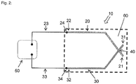
- Thermocouple is provided for measuring the temperature at a measuring point 40. It has a substrate 60 as a carrier element and two metallic conductors 20, 30 which are applied to the substrate 60 by means of thick-film technology, the two conductors 20, 30 at least partially or partially overlapping at the measuring point 40.
- the first conductor 20 has - how Fig. 2 shows - a first end 21 and a first connection end 22, while the second conductor 30 has a second end 31 and a second connection end 32, the first end 21 of the first conductor 20 and the second end 31 of the second conductor 30 at the measuring point 40 are electrically contacted by the two ends 21, 31 overlap.
- the first connection end 22 of the first conductor 20 and the second connection end 32 of the second conductor 30, are each connected to a connection line 23, 33, which lead to a control device 50, so that the circuit necessary for temperature detection is closed.
- the two conductors 20, 30 must consist of different metallic alloys.
- the first conductor 20 consists, for example, of an alloy consisting of 80 to 95% Ni, 3 to 20% Cr, 0 to 1% Fe and 0 to 1% Si, which is available under the brand name ISATHERM PLUS®.
- the second conductor 30 consists of an alloy consisting of 40 to 58% Cu, 40 to 50% Ni, 1 to 5% Mn and 1 to 5% Fe, which is available under the brand name ISA MINUS®.
- the connecting lines 23, 33 consist of the same material as the respectively associated conductors 20 and 30.
- thermocouple 10 detects constant voltage changes which are proportional to the temperature change at the measuring point 40. As a result, it can be concluded from the detected voltage change in the measuring point 40 that there is a relative change in the temperature. If the ambient temperature is additionally recorded as a reference value with the control device 50, for example with an internal separate temperature sensor, the absolute temperature change at the measuring point 40 can also be calculated and this can be displayed directly.
- thermocouple 10 requires only minimal space
- the metallic conductors 20, 30 are applied to the substrate 60 using thick-film technology.
- the conductors 20, 30 have a thickness of only a few micrometers, i.e. the actual dimensions of the entire thermocouple 10 are essentially predetermined by the dimensions of the substrate, which forms a stable support for the metallic conductors, which protects the thermocouple 10 from damage and enables the thermocouple 10 to be attached to an object to be measured.
- the metallic conductors 20, 30 are manufactured using thick-film technology, for example using screen printing technology.
- a first screen printing paste for the first conductor 20 is first produced from ISATHERM PLUS® and applied to the substrate 60 by means of screen printing in a defined area.
- a second screen printing paste for the second conductor 30 is produced from ISA MINUS® and also applied to the substrate 60 in a defined area by means of screen printing, the first end 21 of the first conductor 20 and the second end 31 of the second conductor 30 being on the Overlap measuring point 40 at least in sections.
- a powder is preferably first produced, the respective alloy being melted and then atomized with the supply of inert gas. A powder of metal particles is formed, from which the respective screen printing paste is then formed by adding a solvent.
- This method of preserving the screen printing pastes makes it possible to produce small metal particles with a homogeneous composition and distribution. It is also possible with this method to achieve a relatively uniform size distribution of the individual metal particles. In addition, atomized metal particles have a spherical conformation, whereby a good flow behavior in the subsequent screen printing and thus good screen printing results can be achieved.
- the particle size of the metallic powder should be as similar as possible and the deviations should ideally be in the range of 25%.
- the screen printing paste therefore consists of a mixture of a functional component, namely the respective alloy for the first or second conductor 20, 30 and an organic vehicle.
- the latter has the task of imparting the desired rheological properties to the screen printing paste. It must also ensure a long-term stable, homogeneous dispersion of the functional component in the screen printing paste.
- the solvent is preferably an organic solvent, which is a mixture of an alcohol and an ester, preferably a mixture of ethanol and ethyl acetate. This combination has the advantage that it is volatile.
- the use of an aqueous glycol mixture as a solvent is conceivable. Terpineol can also be used as a thinner.
- the solvent mixture is removed from the printed screen printing paste in a subsequent drying step.
- This drying step can be carried out after each screen printing of the respective screen printing paste, or together after both printing steps, but preferably before sintering, so that the organic solvent can evaporate before the sintering process is carried out.
- the drying process can be carried out at room temperature or accelerated at reduced pressure or elevated temperature, preferably between 50 and 250 ° C. Drying under an air stream is also feasible.
- a long-chain polymer is additionally admixed.
- This long-chain polymer for example ethyl cellulose ECT-10 0100 from Hercules, to the thinner or solvent ensures that the metal particles are always well dispersed within the screen printing paste.
- both conductors are sintered or baked in a subsequent process step at a defined temperature for a predetermined period of time.
- the sintering is advantageously carried out at a temperature of over 700 ° C., preferably at a temperature between 750 ° C. and 900 ° C., particularly preferably at a temperature between 800 ° C. and 875 ° C. It is important here that the sintering temperature is so high that the metal particles combine at least partially with one another and are advantageously baked on the substrate 60.
- the sintering is carried out under a protective gas or hydrogen atmosphere, because the screen printing pastes, which are made from the above-mentioned alloys, easily oxidizable metals such as e.g. Contain Ni, Cu and Fe, which oxidize quickly to the corresponding oxides at the temperatures used for sintering.
- Inert gases such as e.g. Argon or nitrogen can be used.
- hydrogen or gas mixtures such as nitrogen-hydrogen mixtures or air-protective gas mixtures are also used. Therefore, the gas atmosphere does not necessarily have to consist of pure inert gases or reductive gases. Rather, it can also contain air components.
- the time window for the sintering process is at least 150 min. Sintering is preferably carried out over a period of 160 to 200 min, particularly preferably over a period of 170 to 190 min, the latter in particular when the sintering temperature is to be kept low. In this way, the optimal fusion and baking of the screen printing paste on the substrate is made possible.
- both conductors 20, 30 it is possible to print both conductors 20, 30 at the same time and then to dry and burn them in. Alternatively, however, it is also possible to first print, dry and sinter the first conductor 20 and then to design the second conductor 30 in the same way.
- the separate sintering has the advantage that both conductors 20, 30 can be burned in or sintered at different temperatures.
- the substrate 60 is made, for example, of a ceramic or a metal. It must essentially have the desired mechanical properties in order to form a stable and easy-to-use carrier for the thermocouple. Furthermore, it must survive the temperatures required for the sintering processes without damage.
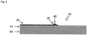
- Fig. 3 schematically shows the cross section of another embodiment of a thermocouple 10, which also has a substrate 60 and a first conductor 20 and a second conductor 30 in a layered arrangement.
- a thermocouple 10 also has a substrate 60 and a first conductor 20 and a second conductor 30 in a layered arrangement.
- the substrate 60 forms the carrier element for the layer-by-layer arrangement of the metallic conductors 20, 30 applied using thick-film technology, the insulating layer 70 also being applied using thick-film technology.
- the insulating layer 70 is therefore preferably a dielectric layer.
- the insulating layer 70 is first applied to the metallic substrate 60 using thick-film technology, dried and baked in a subsequent sintering process. Then, as already described above, the two metallic conductors 20, 30 are printed, dried and baked. It is important here that the sintering temperature for the two conductors 20, 30 is below the sintering temperature for baking the insulating layer 70.
- Fig. 4 shows the schematic partial cross-section of a thermal element 10 according to the invention with a thick-film heater 12.
- the thick-film heater 12 is usually used for heating a hot runner nozzle (not shown). It has a tubular carrier sleeve 60 ', on which an insulating layer 70 is applied using thick-film technology. Resistance tracks 13 are also formed on this in thick-film technology, which are arranged in a defined pattern in order to keep the melt guided in the hot runner nozzle at a temperature which is as uniform as possible over the entire length of the nozzle.
- the metallic conductors 20, 30 are applied to the insulating layer 70 using thick-film technology. The latter are therefore in the same plane as the resistance tracks 13, so that the overall height of the thick-film heater 12 is not increased by the application of the metallic conductors 20, 30. It can be seen that the carrier sleeve 60 ′ together with the insulating layer 70 form the carrier and therefore the substrate for the thermocouple 10. Because the conductors 20, 30 and the thick-film heater 12 are integrated, they do not have to be attached to the thick-film heater 12 as a separate component in a separate manufacturing or assembly step.
- the hot runner nozzle usually has a material tube (not shown), on the outer circumference of which the support sleeve 60 'of the thick-film heater 12 is pushed.
- a material tube not shown
- the resistance tracks 13 of the thick-film heater 12 and the metallic conductors 20, 30 can be printed and sintered simultaneously or in succession. If the resistor tracks 13 and the metallic conductors 20, 30 are sintered one after the other, there is the possibility of burning in the metallic conductors 20, 30 at a higher temperature than the resistor tracks 13 and vice versa. Alloys for the conductors 20, 30 that require significantly higher baking temperatures than the resistance tracks 13 of the thick-film heater 12 can thus also be used. It is also possible to reduce the baking time for the conductors 20, 30 by higher baking temperatures. In each of these cases, the process of forming the metallic conductors 20, 30 for the thermocouple 10 no longer has any influence on the manufacturing process of the thick-film heater 12, in particular the resistance tracks 13.
- the carrier sleeve 60 ' consists of a non-conductive material, for example aluminum oxide, zirconium oxide, silicon nitrite or another ceramic
- the metallic conductors 20, 30 for the thermocouple 10 and the resistance tracks 13 for the heating element 12 can be applied directly to the carrier sleeve 60'
- the insulating layer 70 is first applied and baked.
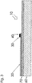
- Fig. 5 schematically shows another embodiment of the layered design of the thermocouple 10 according to the invention for a hot runner nozzle.
- the insulating layer 70 is first applied using thick-film technology.
- This also carries resistance tracks 13, which are formed in thick-film technology and are arranged in a defined pattern, in order to keep the melt guided in the hot runner nozzle at a temperature which is as uniform as possible over the entire length of the nozzle.
- a further insulating layer 70 ′ is applied over the resistance tracks 13 of the thick-film heater 12, which is also implemented using thick-film technology.
- the metallic conductors 20, 30, which overlap in the measuring point 40, are located above this further insulating layer 70 '.
- the thick-film heater 12 is first applied to the carrier sleeve 60 ′ using thick-film technology and baked in by means of a sintering process step.
- the layer structure is then provided with the further insulating layer 70 '.
- the two conductors 20, 30 are then printed on and likewise baked in a sintering process step on the further insulating layer 70 ′ above the thick-film heater 12.
- the sintering temperature for the heater 12 must be higher than for the two conductors 20, 30 that form the thermocouple 10 according to the invention.
- the carrier sleeve 60 ' can also be the material tube of a hot runner nozzle here, i.e. the thick film heater 12 and the thermocouple 10 are an integral part of the hot runner nozzle.
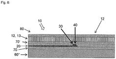
- Fig. 6 shows a schematic partial cross-section of a hot runner nozzle (not designated in any more detail) with a material tube 60 "and a thermocouple 10 according to the invention.
- the material tube 60" of the hot runner nozzle initially carries an insulating layer 70, preferably a dielectric layer, on which the metallic conductors 20, 30 are directly , The latter are covered and insulated by a further insulating layer 70 'in order to be able to apply the electrically conductive resistance tracks 13 of a thick-film heater 12 thereon.
- the resistance tracks 13 of the thick-film heater 12 are therefore arranged above the metallic conductors 20, 30. This makes it possible to use alloys for the metallic conductors 20, 30 which require higher baking temperatures than the resistance tracks 13. Likewise, higher baking temperatures can be used in order to reduce the baking times.
- the metallic conductors 20, 30 can also be formed here over the resistance tracks 13.
- All layers of these embodiments are implemented in thick-film technology, so that the outer dimensions of the material tube 60 "of the hot runner nozzle are only slightly increased by the thick-film heater 12 and the conductors 20, 30.
- a cover layer 80 is finally provided above the heater 12 using thick-film technology. This protects the layer structure from scratching, corrosion or other harmful environmental influences. In addition, this final cover layer 80 also acts as thermal insulation to the outside.
- This cover layer 80 is advantageously a glass, the glass being both a quartz glass, a borosilicate glass, a crown glass, a soda-lime glass, a float glass, a flint glass, etc., which may contain different additives, e.g. Zinc oxide, boron oxide or aluminum oxide and / or other additives such as e.g. May contain iron oxides, copper oxides, cobalt oxides, chromium oxide, uranium oxide, nickel oxide, selenium oxide and / or manganese (IV) oxide.
- This cover layer 80 has the task of protecting the conductors from corrosion and other damage or harmful environmental influences.
- the cover layer 80 is applied by means of screen printing.
- a screen printing paste is made from the material from which the covering layer is to be made and is printed, at least partially, onto the first and second conductors by means of screen printing.
- the cover layer 80 is sintered after the application.
- the covering layer 80 is burned onto the already existing layers and can protect them from external influences and possibly as an additional one Insulating layer act.
- sintering is carried out at a temperature of at least 450 ° C., preferably at a temperature of 500 ° C. to 580 ° C. and particularly preferably at a temperature of 525 ° C. to 560 ° C.
- sintering is advantageously carried out under a protective gas atmosphere. Glasses can also be used that require a significantly higher baking temperature.
- the covering layer 80 is sintered over a period of 7 to 12 minutes, preferably for a period of 10 minutes, in order to prevent possible damage to the layers which have already been applied and baked.
- the invention is not limited to one of the above-described embodiments, but can be modified in many ways.
- the metallic conductors 20, 30 can also consist of other alloy combinations.
- the conductors 20, 30 can consist of ISA MINUS® and ISA PLUS®, ISATHERM MINUS® and ISATHERM PLUS® or ISATHERM MINUS® and ISA PLUS®.
- the names of the above alloys are brand names of Isabellendazzling Heusler GmbH & Co KG, Dillenburg, Germany.
- thermocouple 10 Through a targeted contact of the metallic conductors 20, 30 with a metallically conductive substrate, it is possible to ground the thermocouple 10 electrically. The contact can be achieved either by having a breakdown in the insulating layer 70 or by a protrusion of the metallic conductors 20, 30 beyond the dielectric layer onto the substrate 60.
- screen printing, thermal spraying, pad printing, laser sintering or aerosol printing can be used as a method of thick-film technology.
Landscapes
- Physics & Mathematics (AREA)
- General Physics & Mathematics (AREA)
- Chemical & Material Sciences (AREA)
- Crystallography & Structural Chemistry (AREA)
- Measuring Temperature Or Quantity Of Heat (AREA)
- Resistance Heating (AREA)
Description
- Die Erfindung betrifft ein Thermoelement zur Temperaturerfassung gemäß dem Oberbegriff von Anspruch 1 sowie eine Heißkanaldüse gemäß Anspruch 6.
- Die Temperaturerfassung mittels Thermoelementen in technischen Vorrichtungen stellt häufig eine große Herausforderung dar. Zum einen soll das Thermoelement an einer bestimmten Stelle der Vorrichtung angeordnet sein, um die Temperatur an genau dieser Stelle exakt zu erfassen und um Temperaturänderungen in diesem Bereich der Vorrichtung möglichst zeitnah registrieren zu können. Zum anderen soll das Thermoelement möglichst wenig Raum in Anspruch nehmen, der entweder nicht vorhanden ist oder für andere technische Einrichtungen benötigt wird.
- Die Messung von Temperaturdifferenzen mittels Thermoelementen ist allgemein bekannt. Ein solches Thermoelement hat gewöhnlich zwei elektrische Leiter aus unterschiedlichen metallischen Legierungen oder Metallen, die an einer Messstelle in Kontakt gebracht werden. Die Messung der Temperatur beruht auf der Messung einer Thermospannung. Diese entsteht durch die Umwandlung von thermischer Energie in elektrische Energie aufgrund von Temperaturdifferenzen an der Messstelle gemäß dem Seebeck-Effekt. Thermoelemente werden bevorzugt in Sensoren oder Temperaturmessfühlern eingesetzt und entsprechen derzeit üblicherweise einem Standard nach DIN IEC 584.
-
WO 2008/101172 A2 und DUBY S ET AL: "Printed thick-film thermocouple sensors",ELECTRONICS LETTERS, IEE STEVENAGE, GB, Bd. 41, Nr. 6, 17. März 2005 (2005-03-17), Seiten 312-314, XP006023651,ISSN: 0013-5194, DOI: 10.1049/EL20057988 beschreiben jeweils ein Thermoelement, bei dem sich zwei in Dickschichttechnologie hergestellte Leiter in einer Messstelle überlappen. -
DE 199 41 038 A1 betrifft eine Heißkanaldüse mit einer Heizvorrichtung. Die Heizvorrichtung weist in Dickschichttechnologie hergestellte Widerstandsbahnen auf einem Trägersubstrat auf. Die Widerstandsbahnen geben bei angeschlossener Stromquelle Wärme ab. -
DE 198 14 106 A1 offenbart einen Träger, auf dem ein Thermopaar und ein Heizer mittels eines Dickfilmprozesses aufgebracht wird. -
DE 10 2005 009 927 A1 offenbart ein sogenanntes Mantelthermoelement. Dessen metallische Leiter befinden sich in einer Schutzhülle, die gewöhnlich aus Edelstahl besteht, wobei die beiden Leiter mittels einer Füllung aus Magnesium- oder Aluminiumoxid elektrisch isoliert sind. Von Nachteil hierbei ist, dass die Thermoelemente sehr empfindlich gegen Verbiegen und Verknicken sind. Letzteres kann gegebenenfalls sogar zur Funktionsunfähigkeit führen. Der Platzbedarf derartiger Thermoelemente kann zwar relativ gering sein, wenn diese zu Drähten mit Durchmessern von bis zu 0,5 mm Dicke gezogen werden. Je dünner ein solches Mantelthermoelement ist, desto geringer ist jedoch die mechanische Stabilität, so dass die Gefahr einer mechanischen Verformung und damit eines Defektes steigt. Größere Durchmesser der Mantelthermoelemente führen hingegen zu einer größeren thermischen Masse und bedingen dadurch eine trägere oder längere Ansprechzeit, so dass Temperaturänderungen nur verzögert erfasst werden können. - Ziel der Erfindung ist es, diese und weitere Nachteile des Standes der Technik zu vermeiden und ein Thermoelement zu schaffen, das bei geringem Platzbedarf eine exakte und stets zuverlässige Erfassung einer Temperaturdifferenz oder einer Temperatur ermöglicht und bei kostengünstigem Aufbau eine hohe mechanische Stabilität aufweist. Angestrebt wird ferner ein einfaches und kostengünstiges Verfahren zur Herstellung eines solchen Thermoelements, das auf unterschiedliche Materialien aufbringbar sein soll. Das Thermoelement soll überdies einen möglichst großen Temperaturbereich abdecken und im nutzbaren Temperaturbereich eine möglichst große Spannungsdifferenz bei möglichst minimalen Temperaturänderungen erfassen können.
- Hauptmerkmale der Erfindung sind im kennzeichnenden Teil von Anspruch 1 und in Anspruch 6 angegeben. Ausgestaltungen sind Gegenstand der Ansprüche 2 bis 5 und 7 bis 10.
- Bei einem Thermoelement zur Erfassung der Temperatur an einer Messstelle, mit einem ersten Leiter, der ein erstes Ende und ein erstes Anschlussende aufweist, und mit einem zweiten Leiter, der ein zweites Ende und ein zweites Anschlussende aufweist, wobei das erste Ende des ersten Leiters und das zweite Ende des zweiten Leiters an der Messstelle elektrisch miteinander kontaktiert sind, und wobei das erste Anschlussende des ersten Leiters und das zweite Anschlussende des zweiten Leiters jeweils mit einer Anschlussleitung verbindbar ist, sieht die Erfindung vor, dass der erste Leiter und der zweite Leiter in Dickschichttechnik auf einem Substrat aufgebracht sind, wobei sich das erste Ende des ersten Leiters und das zweite Ende des zweiten Leiters an der Messstelle berühren oder zumindest abschnittsweise überlappen.
- Ein solches Thermoelement hat aufgrund der in Dickschichttechnik auf dem Substrat aufgebrachten Leitern einen äußerst geringen Platzbedarf, weil die Schichtdicke der Leiter nur wenige Mikrometer beträgt. Die Abmessungen des Thermoelements werden daher maßgeblich von dem Substrat selbst vorgegeben, d.h. dessen Abmessungen werden durch das Aufbringen der Leiter in Dickschichttechnik nur unwesentlich verändert, so dass kein zusätzlicher Platzbedarf besteht. Zudem weist das Thermoelement durch das Substrat eine hohe Stabilität auf, weil die auf dem Substrat aufgebrachten Leiter selbst unter großen Belastungen nicht beschädigt werden können.
- Die Leiter lassen sich in Dickschichttechnik präzise und kostengünstig auf dem Substrat aufbringen, was sich zum einen günstig auf die Herstellkosten auswirkt und zum anderen eine hohe Messgenauigkeit gewährleistet. Das erfindungsgemäße Thermoelement weist insbesondere durch seine geringe Masse extrem kurze Ansprechzeiten auf, wodurch Temperaturen direkt vor Ort und in Echtzeit ermittelt werden können. Selbst geringfügige Temperaturschwankungen sind nahezu verzögerungsfrei detektierbar. Das Thermoelement deckt folglich mit den in Dickschichttechnik ausgebildeten Leitern einen relativ großen Temperaturbereich ab, wobei innerhalb nutzbarer Temperaturbereiche bei minimalen Temperaturänderungen eine große Spannungsdifferenz erzeugt wird.
- Die Ausgestaltung der Leiter auf dem Substrat in Dickschichttechnik ermöglicht ferner, die exakte Ausbildung eines Messpunktes, so dass die Möglichkeit besteht, die Temperatur an einem genau zu definierenden Punkt bestimmen zu können, wobei reproduzierbare und genaue Messergebnisse verzögerungsfrei geliefert werden. Weiterhin ist das erfindungsgemäße Thermoelement ohne hohen Materialverbrauch einfach und kostengünstig herstellbar.
- Die minimalen Abmessungen des erfindungsgemäßen Thermoelements ermöglichen eine platzsparende, genaue und punktuelle Messung der Temperatur in einem weiten Temperaturbereich. Damit bieten sich zahlreiche Einsatzbereiche an. Beispielsweise können die Thermoelemente in der Kunststoffverarbeitung, speziell in Heißkanalsystemen bei Temperaturen zwischen Raumtemperatur und 500 °C verwendet werden, indem das Thermoelement direkt auf die Heizung einer Heißkanaldüse oder auf dessen Materialrohr aufgebracht wird. Anwendungen im tiefen Temperaturbereich bis -200 °C und kleiner und weit über 500 °C sind jedoch für das erfindungsgemäße Thermoelement ebenso möglich.
- Erfindungsgemäß ist außerdem vorgesehen, dass der erste Leiter einen positiven Kontakt bildet und aus einer Legierung bestehend aus 80 bis 95 % Ni, 3 bis 20 % Cr, 0 bis 1 % Fe und 0 bis 1 % Si gefertigt ist. Eine Zusammensetzung der oben genannten Legierungen ist auch unter dem Markennamen Chromel® oder ISATHERM PLUS® bekannt. Weiterhin ist erfindungsgemäß vorgesehen, dass der zweite Leiter einen negativen Kontakt bildet und aus einer Legierung bestehend aus 40 bis 58 % Cu, 40 bis 50 % Ni, 1 bis 5 % Mn und 1 bis 5 % Fe gefertigt ist. Eine Zusammensetzung aus diesen Legierungen ist unter dem Markennamen ISA MINUS® bekannt.
- Mit diesen Legierungen werden konstante und reproduzierbare Temperaturmessungen und die Ausgabe eines DIN-konformen Messsignals ermöglicht. Dadurch werden die erhaltenen Messwerte mit anderen genormten Temperaturfühlern vergleichbar. Dies ist insoweit von Bedeutung, da die unterschiedlichen standardisierten Thermoelemente sich aufgrund ihrer unterschiedlichen Kontaktmaterialien in der maximal erzeugbaren Thermospannung und somit in ihrem kritischen Temperaturbereich unterscheiden. Dieser ist charakteristisch für die einzelnen Thermoelemente und stellt den Bereich dar, in welchem die Thermoelemente stabile Thermospannungen liefern, ohne dass die Kontaktmaterialien aufgrund der Hitze beschädigt werden und eine reproduzierbare Thermospannung so verhindert würde.
- Vorzugsweise sind die erste Anschlussleitung des ersten Leiters und die zweite Anschlussleitung des zweiten Leiters aus dem gleichen Material gefertigt, wie die jeweiligen Leiter. Dies gewährleistet ein stabiles Messsignal.
- Eine weitere Ausführungsform der Erfindung sieht vor, dass zwischen einem elektrisch leitenden Substrat und den Leitern eine elektrische Isolierschicht angeordnet ist. Diese ermöglicht einen schichtweisen Aufbau des Thermoelements auf einem metallischen Substrat, ohne dass eine Störung des Thermoelements oder der Spannungsänderung stattfinden kann, indem der Strom über das metallische Substrat abfließen kann. Von besonderem Vorteil ist es, wenn die Isolierschicht eine Dielektrikumsschicht ist. Eine solche lässt sich einfach und kostengünstig in Dickschichttechnik realisieren.
- Ein weiterer Vorteil ergibt sich, wenn über den Leitern und der Isolierschicht zumindest abschnittsweise eine Abdeckschicht aufgebracht ist, wodurch die Leiter vor äußeren Umwelteinflüssen, vor Beschädigung wie Verkratzen oder Oxidation geschützt werden. Zweckmäßig besteht auch die Abdeckschicht aus einem Dielektrikum.
- Ferner ist es möglich, durch Überlappung der Kontakte des Thermoelements über die Dielektrikumsschicht eine leitende Verbindung der Kontakte des Thermofühlers mit dem Substrat zu ermöglichen um dadurch eine elektrische Erdung des Thermoelements zu erreichen.
- Das Thermoelement ist auf einem Substrat angebracht. Erfindungsgemäß ist das Substrat aus einem wärmeleitfähigen Material gefertigt, damit die zu erfassende Temperaturänderung weitestgehend ohne Verzögerung weitergeleitet wird und die Temperaturänderung von dem Thermoelement rasch und präzise ermittelt werden kann. Bei dieser Gestaltung ist das Substrat ein Trägerelement für das Thermoelement. Dadurch erhält das Thermoelement die gleiche Stabilität, wie das Substrat.
- Weiterhin ist erfindungsgemäß vorgesehen, dass auf dem Substrat eine Heizung in Dickschichttechnologie aufgebracht ist. Damit wird die Heizung mit der gleichen Technologie aufgebracht wie das Thermoelement, wodurch die gleichen Produktionsschritte verwendet werden können. Dadurch reduzieren sich sowohl der Zeitaufwand als auch die Herstellungskosten, nicht zuletzt weil standardisierte Produktionsschritte aus der Dickschichttechnologie verwendet werden können.
- In einer andere Ausgestaltung der Erfindung ist das Substrat zumindest ein Teil einer Heißkanaldüse, indem die Leiter des Thermoelements auf der Düse oder auf deren Heizung aufgebracht werden. Dadurch wird es ermöglicht, eine Heißkanaldüse direkt mit einem Thermoelement zu versehen, womit die Temperatur an einem exakt definierten Punkt auf der Heißkanaldüse ohne jegliche Messverzögerung detektiert werden kann. Das Substrat des Thermoelements bildet in diesen Fällen entweder die Heißkanaldüse selbst oder deren Heizung. Durch das Aufbringen der Leiter des Thermoelements in Dickschichttechnik werden die Abmessungen der Heißkanaldüse oder deren Heizung nicht merklich verändert, so dass das Thermoelement selbst keinen nennenswerten Raum einnimmt. Darüber hinaus gewährleisten die in Dickschichttechnik aufgebrachten Leiter eine schnelle und exakte Temperaturbestimmung an einem genau definierten Messpunkt auf der Heißkanaldüse bzw. auf deren Heizung.
- Dementsprechend kann in einer Weiterbildung der Erfindung das Substrat des erfindungsgemäßen Thermoelements ein Materialrohr der Heißkanaldüse sein, welches das aufgeschmolzene Material zur Austrittsöffnung der Heißkanaldüse befördert. Das Materialrohr dient mithin der Zuführung des zu verarbeitenden Materials in ein Formnest, wobei es von besonderer Bedeutung, das Material innerhalb des gesamten Materialrohrs auf einer konstanten Temperatur zu halten. Diese kann mit dem erfindungsgemäßen Thermoelement exakt und ohne großen Platzbedarf ermittelt werden.
- Entsprechend einer weiteren Ausgestaltung der Erfindung ist das Substrat des Thermoelements eine Heizung oder ein Heizelement der Heißkanaldüse. Bei diesem Aufbau wird das Thermoelement in Dickschichttechnik direkt unter oder über der Heizung der Heißkanaldüse aufgebracht. Dadurch ist es möglich, an definierten Stellen unmittelbar die Temperatur der Heizung oder deren Umgebung zu erfassen, um beispielsweise die Heizleistung der Heizung exakt bestimmen und regeln zu können. Darüber hinaus ist es möglich, die Temperatur unmittelbar an der Heizung zu ermitteln, um diese dadurch direkt und präzise regeln zu können. Dabei ist es von Vorteil, wenn die Leiter des Thermoelements direkt auf den Heizleitern oder den Heizleiterbahnen ausgebildet sind. Letztere können gleichfalls in Dickschichttechnik ausgebildet sein, was sich günstig auf die Bauhöhe der Heizung auswirkt, die weder durch die Heizleiterbahnen noch durch die Leiter des Thermoelements wesentlich verändert wird. Auf diese Weise lassen sich die Vorteile der Dickschichtheizung mit dem in Dickschichttechnologie aufgebrachten Thermoelement vereinen. Die Herstellkosten lassen sich senken, weil das Thermoelement mit der gleichen Technologie aufgebracht wird. Weiterhin ist eine Miniaturisierung der Heißkanaldüse möglich, weil sowohl die Dickschichtheizung als auch das Thermoelement einen nur geringen Platzbedarf aufweisen und keine zusätzliche Baugruppe erforderlich ist. Auch das ansonsten übliche Anschweißen eines zusätzlichen Drahtfühlers zur Temperaturbestimmung entfällt, weil das Thermoelement direkt auf der Heißkanaldüse und/oder auf deren Heizung aufgebracht ist.
- Konstruktiv ist es günstig, wenn die Leiter des Thermoelements und die Widerstandsbahnen durch mechanische Schlitze oder Nuten voneinander getrennt sind. Dadurch wird eine zuverlässige thermische und elektrische Trennung des Thermoelements von den aktiven Widerstandsbahnen erreicht. Es wird somit ermöglicht, die Temperatur in direkter Nähe der Heizung zu erfassen, ohne dabei die Temperatur direkt an, auf oder unter der Heizung zu messen, was für zahlreiche Anwendungen wichtig sein kann. Das Einbringen der Schlitze oder Nuten lässt sich mit einfachen Mitteln kostengünstig realisieren und hat keinen Einfluss auf den Platzbedarf des Thermoelements.
- Als besonders vorteilhafte Ausgestaltung der Erfindung hat sich ein Thermoelement erwiesen, bei dem der erste Leiter aus einer Legierung bestehend aus 89,1 % Ni, 10 %Cr, 0,5 % Si und 0,4 % Fe gefertigt ist und bei dem der zweite Leiter aus einer Legierung bestehend aus 51 % Cu, 45 % Ni, 2 % Mn und 2 % Fe gefertigt ist. Das Rohmaterial, welches für den ersten Leiter benutzt wurde, ist unter dem Markennamen ISATHERM PLUS® erhältlich und wurde von der Isabellenhütte Heusler GmbH & Co KG, Dillenburg, Germany bezogen, ebenso wie das Rohmaterial für den zweiten Leiter, welches unter dem Markennamen ISA MINUS® erhältlich ist. Die chemische Zusammensetzung der Legierungen ist in Massenanteilen (Massenprozent) des jeweiligen Elements angegeben.
- Weiterhin sind auch Materialkombinationen der Legierungen ISA MINUS® mit ISA PLUS®, ISATHERM MINUS® mit ISATHERM PLUS® und ISATHERM MINUS® mit ISA PLUS® möglich, die ebenfalls von der Isabellenhütte Heusler GmbH & Co KG, Dillenburg, Germany bezogen wurden.
- Die Erfindung sieht ferner eine Heißkanaldüse mit einer Heizung vor, auf der ein erfindungsgemäßes Thermoelement angeordnet oder aufgebracht ist. Gerade bei einer Heißkanaldüse ist es wichtig, die Temperatur des zu verarbeitenden Materials genau bestimmen zu können, um eine optimale Verarbeitung der zu verarbeitenden Masse gewährleisten zu können. Bei dem erfindungsgemäßen Aufbau einer Heißkanaldüse kann das Thermoelement zur Bestimmung der Temperatur an einem genau definierten Messpunkt, bevorzugt an der Spitze der Heißkanaldüse, äußerst platzsparend angebracht werden. Dies ermöglicht eine exakte Überwachung und Regelung der Temperatur.
- Weil das erfindungsgemäße Thermoelement eine sehr schnelle Ansprechzeit hat, ist es möglich, Temperaturänderungen an der Heißkanaldüse in Echtzeit zu ermitteln. Dadurch kann eine optimale Verarbeitungstemperatur des Materials innerhalb der Heißkanaldüse gewährleistet werden, was sich äußerst günstig auf die Produktionsbedingungen auswirkt. Auch die Temperaturerfassung in der Nähe der Heizung stellt eine bevorzugte Bauart der Erfindung dar, weil somit die Leistung der Heizung exakt über die tatsächlich herrschende Temperatur geregelt werden kann, wobei die Temperatur von dem erfindungsgemäßen Thermoelement ermittelt wird.
- Dazu sieht die Erfindung weiter vor, dass die Heizung eine Dickschichtheizung mit Widerstandsbahnen ist, wobei das Thermoelement über den Widerstandsbahnen, unter den Widerstandsbahnen oder in der gleichen Ebene wie die Widerstandsbahnen angeordnet ist. Dies ermöglicht zahlreiche Ausgestaltungen der Heißkanaldüse, die problemlos an unterschiedliche Einsatzbedingungen angepasst werden kann. Die Widerstandsbahnen der Dickschichtheizung und die Leiter des Thermoelements lassen sich gleichzeitig oder in einer bestimmten Reihenfolge nacheinander bzw. voreinander aufbringen, was sich günstig auf das spätere Verhalten des Thermoelements auswirkt, insbesondere wenn letzteres vor den Widerstandsbahnen der Dickschichtheizung auf dem Substrat aufgebracht wird.
- Eine zwischen der Heizung und dem Thermoelement vorgesehene Isolierschicht verhindert eine verfälschte Temperaturerfassung durch Spannungsverschiebungen, die durch die elektrische Heizung und unterschiedliche Heizleistungen der Heizung möglich sind.
- Eine über der Heizung vorgesehene Abdeckschicht schützt sowohl das Thermoelement als auch die Heizung der Heißkanaldüse vor Beschädigungen oder äußeren Umwelteinflüssen wie Verkratzen, Korrosion oder Oxidation. Zudem wirkt die Abdeckschicht als thermische Isolierung gegenüber der Umgebung.
- Weitere Merkmale, Einzelheiten und Vorteile der Erfindung ergeben sich aus dem Wortlaut der Ansprüche sowie aus der folgenden Beschreibung von Ausführungsbeispielen anhand der Zeichnungen. Es zeigen:
- Fig. 1
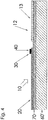
- ein schematischer Teil-Querschnitt eines Thermoelements;
- Fig. 2
- eine schematische Darstellung des Aufbaus eines Thermoelements, das über Anschlussleitungen mit einem Regelgerät verbunden ist;
- Fig. 3
- ein schematischer Teil-Querschnitt einer anderen Ausführungsform eines Thermoelements;
- Fig. 4
- ein schematischer Teil-Querschnitt eines erfindungsgemäßen Thermoelements;
- Fig. 5
- ein schematischer Teil-Querschnitt einer anderen Ausführungsform des erfindungsgemäßen Thermoelements; und
- Fig. 6
- ein schematischer Teil-Querschnitt einer Heißkanaldüse mit einem erfindungsgemäßen Thermoelement.
- Gleiche Bezugszeichen beziehen sich nachfolgend auf gleiche oder gleichartige Bauteile.
- Das in
Fig. 1 allgemein mit 10 bezeichnete Thermoelement ist für die Erfassung der Temperatur an einer Messstelle 40 vorgesehen. Es hat ein Substrat 60 als Trägerelement sowie zwei metallische Leiter 20, 30, die mittels Dickschichttechnik auf dem Substrat 60 aufgebracht sind, wobei sich die beiden Leiter 20, 30 an der Messstelle 40 zumindest abschnittsweise bzw. teilweise überlappen. - Der erste Leiter 20 hat - wie
Fig. 2 zeigt - ein erstes Ende 21 und ein erstes Anschlussende 22, während der zweite Leiter 30 ein zweites Ende 31 und ein zweites Anschlussende 32 aufweist, wobei das erste Ende 21 des ersten Leiters 20 und das zweite Ende 31 des zweiten Leiters 30 an der Messstelle 40 elektrisch miteinander kontaktiert sind, indem die beiden Enden 21, 31 sich überlappen. Das erste Anschlussende 22 des ersten Leiters 20 und das zweite Anschlussende 32 des zweiten Leiters 30 sind hingegen mit je einer Anschlussleitung 23, 33 verbunden, die zu einem Regelgerät 50 führen, damit der für die Temperaturerfassung notwendige Stromkreis geschlossen ist. - Um mit dem Thermoelement 10 Temperaturen erfassen zu können, müssen die beiden Leiter 20, 30 aus unterschiedlichen metallischen Legierungen bestehen.
- Der erste Leiter 20 besteht beispielsweise aus einer Legierung bestehend aus 80 bis 95 % Ni, 3 bis 20 % Cr, 0 bis 1 % Fe und 0 bis 1 % Si, die unter dem Markennamen ISATHERM PLUS® erhältlich ist. Der zweite Leiter 30 besteht aus einer Legierung bestehend aus 40 bis 58 % Cu, 40 bis 50 % Ni, 1 bis 5 % Mn und 1 bis 5 % Fe, die unter dem Markennamen ISA MINUS® erhältlich ist. Die Anschlussleitungen 23, 33 bestehen aus dem gleichen Material, wie die jeweils zugehörigen Leiter 20 bzw. 30.
- Ändert sich die Temperatur des Substrats 60, so entsteht an der Messstelle 40, an der die beiden Leiter 20 und 30 die Überlappung bilden, eine elektrische Spannung, die mit dem Regelgerät 50, das über die Anschlussleitungen 23, 33 mit den Leitern 20, 30 in elektrischem Kontakt steht, gemessen werden kann.
- Das erfindungsgemäße Thermoelement 10 erfasst konstante Spannungsänderungen, die proportional zur Temperaturänderung an der Messstelle 40 sind. Dadurch kann von der erfassten Spannungsänderung in der Messstelle 40 auf eine relative Änderung der Temperatur geschlossen werden. Erfasst man mit dem Regelgerät 50 zusätzlich die Umgebungstemperatur als Referenzwert, beispielsweise mit einem internen separaten Temperaturfühler, lässt sich zudem die absolute Temperaturänderung an der Messstelle 40 berechnen und es besteht die Möglichkeit, diese direkt anzuzeigen.
- Damit das Thermoelement 10 einen nur minimalen Platzbedarf benötigt, sind die metallischen Leiter 20, 30 in Dickschichttechnik auf das Substrat 60 aufgebracht. Dadurch weisen die Leiter 20, 30 eine Dicke von nur wenigen Mikrometern auf, d.h. die eigentlichen Abmessungen des gesamten Thermoelements 10 werden im Wesentlichen von den Abmessungen des Substrats vorgegeben, welches für die metallischen Leiter einen stabilen Träger bildet, der das Thermoelement 10 vor Beschädigungen schützt und das Anbringen des Thermoelements 10 an ein zu vermessendes Objekt ermöglicht.
- Die Herstellung der metallischen Leiter 20, 30 in Dickschichttechnik erfolgt beispielsweise mittels der Siebdrucktechnik. Dazu wird zunächst eine erste Siebdruckpaste für den ersten Leiter 20 aus ISATHERM PLUS® hergestellt und in einem definierten Bereich mittels Siebdruck auf das Substrat 60 aufgebracht. Anschließend wird eine zweite Siebdruckpaste für den zweiten Leiter 30 aus ISA MINUS® hergestellt und ebenfalls mittels Siebdruck in einem definierten Bereich auf dem Substrat 60 aufgetragen, wobei sich das erste Ende 21 des ersten Leiters 20 und das zweite Ende 31 des zweiten Leiters 30 an der Messstelle 40 zumindest abschnittsweise überlappen.
- Zur Herstellung der Siebdruckpasten für die Leiter 20, 30 wird vorzugsweise zunächst ein Pulver hergestellt, wobei die jeweilige Legierung aufgeschmolzen und anschließend unter Zuleitung von Inertgas verdüst wird. Dabei bildet sich ein Pulver aus Metallpartikeln, aus welchem anschließend durch Zugabe eines Lösungsmittels die jeweilige Siebdruckpaste gebildet wird.
- Diese Methode zum Erhalt der Siebdruckpasten ermöglicht es, kleine Metallpartikel mit einer homogenen Zusammensetzung und Verteilung zu erzeugen. Außerdem ist es mit dieser Methode möglich, eine relativ einheitliche Größenverteilung der einzelnen Metallpartikel zu erreichen. Darüber hinaus weisen verdüste Metallpartikel eine sphärische Konformation auf, wodurch sich ein gutes Fließverhalten im anschließenden Siebdruck und damit gute Siebdruckergebnisse erzielen lassen.
- Die Partikelgröße des metallischen Pulvers sollte möglichst ähnlich sein und die Abweichungen idealerweise im Bereich von 25 % liegen. Je geringer die Partikelgröße, desto niedriger können Sintertemperaturen und -zeiten gewählt werden. Vorteilhaft sind daher Partikelgrößen von 5 Mikrometern. Einsetzbar sind aber problemlos auch Partikelgrößen zwischen 20 bis 25 µm.
- Es sind auch andere Methoden für die Herstellung einer Siebdruckpaste vorstellbar wie z.B. das mechanische Zerkleinern der Legierungen z.B. durch einen Mahlvorgang.
- Die Siebdruckpaste besteht mithin aus einem Gemisch aus einer funktionellen Komponente, namentlich der jeweiligen Legierung für den ersten oder zweiten Leiter 20, 30 sowie einem organischen Vehikel. Letzteres hat die Aufgabe der Siebdruckpaste die gewünschten rheologischen Eigenschaften zu verleihen. Es muss zusätzliche eine langzeitstabile, homogene Dispersion der funktionellen Komponente in der Siebdruckpaste gewährleisten.
- Das Lösungsmittel ist bevorzugt ein organisches Lösungsmittel, wobei es sich um ein Gemisch aus einem Alkohol und einem Ester handelt, bevorzugt um ein Gemisch aus Ethanol und Essigsäureethylester. Diese Kombination bietet den Vorteil, dass es leicht flüchtig ist. Vorstellbar ist die Verwendung eines wässrigen Glykolgemisches als Lösungsmittel. Auch Terpineol kann als Verdünner eingesetzt werden.
- Das Lösungsmittelgemisch wird nach dem Siebdruck der Metallpasten in einem nachfolgenden Trocknungsschritt aus der gedruckten Siebdruckpaste entfernt. Dieser Trocknungsschritt kann nach jedem Siebdruck der jeweiligen Siebdruckpaste erfolgen, oder aber nach beiden Druckschritten gemeinsam, bevorzugt jedoch vor dem Sintern, damit das organische Lösungsmittel verdampfen kann, bevor der Sinterprozess durchgeführt wird. Der Trocknungsvorgang kann bei Raumtemperatur oder beschleunigt bei Unterdruck oder erhöhter Temperatur, bevorzugt zwischen 50 und 250 °C durchgeführt werden. Das Trocknen unter einem Luftstrom ist ebenfalls durchführbar.
- In einer vorteilhaften Ausgestaltung der Siebdruckpasten hat sich gezeigt, dass zusätzlich ein langkettiges Polymer zugemischt wird. Der Zusatz dieses langkettigen Polymers, beispielsweise Ethylzellulose ECT-10 0100 der Firma Hercules, zu dem Verdünner bzw. Lösungsmittel gewährleistet eine stets gute Dispersion der Metallpartikel innerhalb der Siebdruckpaste.
- Nach dem Aufdrucken der einzelnen Siebdruckpasten für den ersten Leiter 20 und den zweiten Leiter 30 auf dem Substrat 60 und nach dem anschließenden Trocknen des gedruckten Musters, werden beide Leiter in einem nachfolgenden Prozessschritt bei einer definierten Temperatur für einen vorgegebenen Zeitraum gesintert bzw. eingebrannt.
- Vorteilhafterweise wird das Sintern bei einer Temperatur von über 700 °C durchgeführt, bevorzugt bei einer Temperatur zwischen 750 °C und 900 °C, besonders bevorzugt bei einer Temperatur zwischen 800 °C und 875 °C. Wichtig hierbei ist, dass die Sintertemperatur so hoch liegt, dass die Metallpartikel sich zumindest teilweise miteinander verbinden und vorteilhafterweise auf dem Substrat 60 eingebrannt werden. Idealerweise wird das Sintern unter Schutzgas- oder Wasserstoffatmosphäre durchgeführt, weil die Siebdruckpasten, die aus den oben genannten Legierungen hergestellt sind, leicht oxidierbare Metalle wie z.B. Ni, Cu und Fe enthalten, die bei den zum Sintern verwendeten Temperaturen rasch zu den entsprechenden Oxiden oxidieren. Als Schutzgase sind Inertgase wie z.B. Argon oder Stickstoff verwendbar. Eingesetzt werden aber auch Wasserstoff oder Gasgemische wie Stickstoff-Wasserstoff-Gemische oder Luft-Schutzgas-Gemische. Mithin muss die Gasatmosphäre nicht notwendigerweise aus reinen Inertgasen oder reduktiven Gasen bestehen. Sie kann vielmehr auch Luftanteile enthalten.
- Das Zeitfenster für den Sinterprozess beträgt mindestens 150 min. Bevorzugt wird über einen Zeitraum von 160 bis 200 min gesintert, besonders bevorzugt über einen Zeitraum von 170 bis 190 min, letzteres insbesondere dann, wenn die Sintertemperatur niedrig gehalten werden soll. Auf diese Weise wird das optimale Verschmelzen und Einbrennen der Siebdruckpaste auf das Substrat ermöglicht.
- Insgesamt ist es möglich, beide Leiter 20, 30 gelichzeitig zu drucken und anschließend zu trocknen und einzubrennen. Alternativ ist es aber auch möglich, zunächst den ersten Leiter 20 aufzudrucken, zu trocknen und zu sintern und anschließend den zweiten Leiter 30 in gleicher Art und Weise auszuführen. Das getrennte Sintern hat den Vorteil, dass beide Leiter 20, 30 bei unterschiedlichen Temperaturen eingebrannt bzw. gesintert werden können.
- Das Substrat 60 ist beispielsweise aus einer Keramik oder einem Metall gefertigt. Es muss im Wesentlichen die gewünschten mechanischen Eigenschaften haben, um für das Thermoelement einen stabilen und einfach zu handhabenden Träger zu bilden. Ferner muss es die für die Sinterprozesse notwendigen Temperaturen unbeschadet überstehen.
-
Fig. 3 zeigt schematisch den Querschnitt einer anderen Ausführungsform eines Thermoelements 10, das ebenfalls in einer schichtweisen Anordnung ein Substrat 60 sowie einen ersten Leiter 20 und einen zweiten Leiter 30 aufweist. Zwischen dem Substrat 60 und den Leitern 20, 30 befindet sich jedoch eine zusätzliche Isolierschicht 70, welche das Substrat 60 und die Leiter 20, 30 elektrisch voneinander trennt. Damit ist es möglich, das Substrat 60 aus einem elektrisch leitenden Material, beispielsweise einem Metall zu fertigen. - Das Substrat 60 bildet auch hier das Trägerelement für die schichtweise Anordnung der in Dickschichttechnik aufgebrachten metallischen Leiter 20, 30, wobei auch die Isolierschicht 70 in Dickschichttechnik aufgebracht wird. Bei der Isolierschicht 70 handelt es sich daher bevorzugt um eine Dielektrikumsschicht.
- Bei der Herstellung des erfindungsgemäßen Thermoelements 10 wird zuerst die Isolierschicht 70 in Dickschichttechnik auf das metallische Substrat 60 aufgebracht, getrocknet und in einem anschließenden Sinterprozess eingebrannt. Anschließend werden - wie oben bereits beschrieben - die beiden metallischen Leiter 20, 30 aufgedruckt, getrocknet und eingebrannt. Wichtig hierbei ist, dass die Sintertemperatur für die beiden Leiter 20, 30 unterhalb der Sintertemperatur für das Einbrennen der Isolierschicht 70 liegt.
-
Fig. 4 zeigt den schematischen Teil-Querschnitt eines erfindungsgemäßen Thermolements 10 mit einer Dickschichtheizung 12. Die Dickschichtheizung 12 wird gewöhnlich zum Beheizen einer (nicht dargestellten) Heißkanaldüse verwendet. Sie hat eine rohrförmige Trägerhülse 60', auf dem in Dickschichttechnik eine Isolierschicht 70 aufgebracht ist. Auf dieser sind ebenfalls in Dickschichttechnik Widerstandsbahnen 13 ausgebildet, die in einem definierten Muster angeordnet sind, um die in der Heißkanaldüse geführte Schmelze über die gesamte Länge der Düse auf einer möglichst gleichmäßigen Temperatur zu halten. - Neben den Widerstandsbahnen 13 der Dickschichtheizung 12 sind auf der Isolierschicht 70 die metallischen Leiter 20, 30 in Dickschichttechnik aufgebracht. Letzter liegen damit in der gleichen Ebene wie die Widerstandsbahnen 13, so dass sich die Bauhöhe der Dickschichtheizung 12 durch das Aufbringen der metallischen Leiter 20, 30 nicht vergrößert. Man erkennt, dass die Trägerhülse 60' zusammen mit der Isolierschicht 70 den Träger und mithin das Substrat für das Thermoelement 10 bilden. Weil die Leiter 20, 30 und die Dickschichtheizung 12 integriert sind, müssen sie nicht in einem separaten Fertigungs- oder Montageschritt als separates Bauteil an der Dickschichtheizung 12 befestigt werden.
- Die Heißkanaldüse hat gewöhnlich ein (nicht gezeigtes) Materialrohr, auf dessen Außenumfang die Trägerhülse 60' der Dickschichtheizung 12 aufgeschoben ist. Alternativ ist es aber auch möglich, die Isolierschicht 70 und die Widerstandsbahnen der Dickschichtheizung 12 unmittelbar auf dem Materialrohr aufzubringen. Das gleiche gilt entsprechend für die metallischen Leiter 20, 30.
- Das Herstellen der Siebdruckpasten sowie das Aufdrucken der einzelnen Schichten und das anschließende Trocknen und Sintern erfolgt wie bereits oben beschrieben.
- Eine wichtige Option bei dieser Ausführungsform besteht jedoch darin, dass die Widerstandsbahnen 13 der Dickschichtheizung 12 und die metallischen Leiter 20, 30 gleichzeitig oder nacheinander gedruckt und gesintert werden können. Werden die Widerstandbahnen 13 und die metallischen Leiter 20, 30 nacheinander gesintert, besteht die Möglichkeit, die metallischen Leiter 20, 30 bei einer höheren Temperatur einzubrennen als die Widerstandsbahnen 13 und umgekehrt. Damit können auch Legierungen für die Leiter 20, 30 zum Einsatz kommen, die deutlich höhere Einbrenntemperaturen benötigen als die Widerstandsbahnen 13 der Dickschichtheizung 12. Möglich ist auch, durch höhere Einbrenntemperaturen für die Leiter 20, 30 deren Einbrennzeit zu verringern. In jedem dieser Fälle hat dann der Prozess der Ausbildung der metallischen Leiter 20, 30 für das Thermoelement 10 keinen Einfluss mehr auf den Fertigungsprozess der Dickschichtheizung 12, insbesondere der Widerstandsbahnen 13.
- Besteht die Trägerhülse 60' aus einem nicht leitenden Material, beispielsweise aus Aluminiumoxid, Zirkonoxid, Siliziumnitrit oder einer andere Keramik, können die metallischen Leiter 20, 30 für das Thermoelement 10 und die Widerstandsbahnen 13 für das Heizelement 12 direkt auf die Trägerhülse 60' aufgebracht werden. Besteht diese hingegen aus einem metallischen Material, so wird zunächst die Isolierschicht 70 aufgebracht und eingebrannt.
-
Fig. 5 zeigt schematisch eine andere Ausführungsform der schichtweisen Ausbildung des erfindungsgemäßen Thermoelements 10 für eine Heißkanaldüse. - Auf der meist aus einer Stahllegierung gefertigten Trägerhülse 60' ist zunächst die Isolierschicht 70 in Dickschichttechnik aufgebracht. Diese trägt ebenfalls in Dickschichttechnik ausgebildete Widerstandsbahnen 13, die in einem definierten Muster angeordnet sind, um die in der Heißkanaldüse geführte Schmelze über die gesamte Länge der Düse auf einer möglichst gleichmäßigen Temperatur zu halten. Über den Widerstandsbahnen 13 der Dickschichtheizung 12 ist eine weitere Isolierschicht 70' aufgebracht, die gleichfalls in Dickschichttechnik ausgeführt ist. Über dieser weiteren Isolierschicht 70' befinden sich die metallischen Leiter 20, 30, die sich in dem Messpunkt 40 überlappen.
- Zur Herstellung einer solchen Anordnung wird zuerst die Dickschichtheizung 12 in Dickschichttechnologie auf die Trägerhülse 60' aufgebracht und mittels eines Sinterprozessschritts eingebrannt. Anschließend wird der Schichtaufbau mit der weiteren Isolierschicht 70' versehen. Danach werden die beiden Leiter 20, 30 aufgedruckt und ebenfalls in einem Sinterprozessschritt auf der weiteren Isolierschicht 70' über der Dickschichtheizung 12 eingebrannt. Dabei ist zu beachten, dass die Sintertemperatur für die Heizung 12 höher sein muss, als für die beiden Leiter 20, 30, die das erfindungsgemäße Thermoelement 10 bilden. Die Trägerhülse 60' kann auch hier bereits das Materialrohr einer Heißkanaldüse sein, d.h. die Dickschichtheizung 12 und das Thermoelement 10 sind integraler Bestandteil der Heißkanaldüse.
-
Fig. 6 zeigt einen schematischen Teil-Querschnitt einer (nicht näher bezeichneten) Heißkanaldüse mit einem Materialrohr 60" und einem erfindungsgemäßen Thermoelement 10. Das Materialrohr 60" der Heißkanaldüse trägt zunächst eine Isolierschicht 70, vorzugsweise eine Dielektrikumsschicht, auf der unmittelbar die metallischen Leiter 20, 30 sind. Letztere werden von einer weiteren Isolierschicht 70' abgedeckt und isoliert, um auf dieser die elektrisch leitfähigen Widerstandsbahnen 13 einer Dickschichtheizung 12 aufbringen zu können. - In diesem Ausführungsbeispiel sind mithin die Widerstandsbahnen 13 der Dickschichtheizung 12 über den metallischen Leitern 20, 30 angeordnet. Dadurch ist es möglich, Legierungen für die metallischen Leiter 20, 30 zu verwenden, die höhere Einbrenntemperaturen benötigen als die Widerstandsbahnen 13. Ebenso sind höhere Einbrenntemperaturen einsetzbar, um die Einbrennzeiten zu verringern.
- Alternativ kann man die metallischen Leiter 20, 30 auch hier über den Widerstandsbahnen 13 ausbilden.
- Sämtliche Schichten dieser Ausführungsformen sind in Dickschichttechnik ausgeführt, so dass die Außenabmessungen des Materialrohrs 60" der Heißkanaldüse durch die Dickschichtheizung 12 und die Leiter 20, 30 nur unwesentlich vergrößert werden.
- Um sowohl die Dickschichtheizung 12 als auch die Leiter 20, 30 vor äußeren Einflüssen zu schützen und zu isolieren, ist abschließend in Dickschichttechnik eine Abdeckschicht 80 oberhalb der Heizung 12 vorgesehen. Dies schützt den Schichtaufbau vor Verkratzen, Korrosion oder sonstigen schädlichen Umwelteinflüssen. Zudem wirkt diese abschließende Abdeckschicht 80 auch als thermische Isolation nach außen.
- Diese Abdeckschicht 80 ist vorteilhafterweise ein Glas, wobei das Glas sowohl ein Quarzglas, ein Borsilikatglas, ein Kronglas, ein Kalk-Natron-Glas, ein Floatglas, ein Flintglas usw. sein kann, welches gegebenenfalls unterschiedliche Zuschlagstoffe, wie z.B. Zinkoxid, Boroxid oder Aluminiumoxid und/oder weitere Zusatzstoffe wie z.B. Eisenoxide, Kupferoxide, Cobaltoxide, Chromoxid, Uranoxid, Nickeloxid, Selenoxid und/oder Mangan(IV)oxid enthalten kann. Diese Abdeckschicht 80 hat die Aufgabe, die Leiter vor Korrosion und sonstigen Beschädigungen oder schädlichen Umwelteinflüssen zu schützen.
- Die Abdeckschicht 80 wird ebenso wie alle anderen Schichten mittels Siebdruck aufgebracht. Dazu wird eine Siebdruckpaste aus dem Material, aus dem die Abdeckschicht bestehen soll, angefertigt und mittels Siebdruck auf den ersten und zweiten Leiter, zumindest partiell, aufgedruckt. Alternativ ist es auch möglich, die Abdeckschicht auf eine aufliegende Heizung oder eine Isolierschicht aufzudrucken.
- Nach einem möglichen Trocknungsschritt wird die Abdeckschicht 80 nach dem Aufbringen gesintert. Dadurch wird die Abdeckschicht 80 auf die schon vorhandenen Schichten eingebrannt und kann diese vor äußeren Einflüssen schützen und eventuell als eine zusätzliche Isolierschicht wirken. Abschließend wird bei einer Temperatur von mindestens 450 °C gesintert, bevorzugt bei einer Temperatur von 500 °C bis 580 °C und besonders bevorzugt bei einer Temperatur von 525 °C bis 560 °C. Um die eventuell nicht abgedeckten Leiter 20, 30 vor Oxidation zu schützen, wird vorteilhafterweise unter Schutzgasatmosphäre gesintert. Es können auch Gläser zum Einsatz kommen, die eine wesentlich höhere Einbrenntemperatur benötigen. Um die Abdeckschicht 80 auf dem Substrat, dem Leiter, der Heizung oder der Isolierschicht einzubrennen, schließt sich ein letzter und sehr kurz gehaltener Sintervorgang an. Die Abdeckschicht 80 wird dazu über einen Zeitraum von 7 bis 12 min gesintert, bevorzugt für einen Zeitraum von 10 min, um so eine eventuelle Beschädigung der schon aufgebrachten und eingebrannten Schichten zu verhindern.
- Die Erfindung ist nicht auf eine der vorbeschriebenen Ausführungsformen beschränkt, sondern in vielfältiger Weise abwandelbar. So können die metallischen Leiter 20, 30 auch aus anderen Legierungskombinationen bestehen. Beispielsweise können die Leiter 20, 30 in einer Ausführungsform aus ISA MINUS® und ISA PLUS®, ISATHERM MINUS® und ISATHERM PLUS® oder ISATHERM MINUS® und ISA PLUS® bestehen. Die Bezeichnungen der oben genannten Legierungen sind Markennamen der Isabellenhütte Heusler GmbH & Co KG, Dillenburg, Germany.
- In den oben aufgeführten Legierungen könnte optional auch Silizium mit Germanium substituiert werden, oder Mangan mit Rhenium, da diese vergleichbare chemische Eigenschaften besitzen. Durch einen gezielten Kontakt der metallischen Leiter 20, 30 zu einem metallisch leitenden Substrat ist es möglich, das Thermoelement 10 elektrisch zu erden. Der Kontakt kann entweder dadurch erreicht werden, dass innerhalb der Isolierschicht 70 ein Durchbruch vorhanden ist oder durch eine Überstand der metallischen Leiter 20, 30 über die Dielektrikumsschicht hinaus auf das Substrat 60.
- Als Verfahren der Dickschichttechnik können - wie oben dargestellt - der Siebdruck, das thermische Spritzen, der Tampondruck, das Lasersintern oder das Aerosoldrucken verwendet werden.
- Die wesentlichen Vorteile der Erfindung stellen sich wie folgt dar:
- ▪ Kaum auf das Messobjekt aufbauende Geometrie (nur wenige Mikrometer);
- Dennoch mechanisch so stabil wie das Substrat auf das es gedruckt wird;
- ▪ Geringe thermische Masse, somit extrem schnelle Ansprechzeit;
- ▪ Bei Integration in einen Dickschichtheizer keine zusätzliche Baugruppe;
- ▪ DIN-Konformes bzw. ähnliches Messsignal (Abweichung kleiner +/-5%);
- ▪ Kleiner, klar definierter Messpunkt (vor allem bei Heizern mit inhomogener Leistungs- bzw.Temperaturverteilung vorteilhaft).
| 10 | Thermoelement | 31 | Zweites Ende |
| 11 | Heizung | 32 | Zweite Anschlussstelle |
| 12 | Dickschichtheizung | 33 | Zweite Anschlussleitung |
| 13 | Widerstandsbahnen | 34 | Zweite Kontaktstelle |
| 14 | Schlitze | 35 | Zweiter Leiter mit weitere Messstelle |
| 15 | Nuten | 40 | Messstelle |
| 20 | Erster Leiter | 50 | Regelgerät |
| 21 | Erstes Ende | 60 | Substrat |
| 22 | Erste Anschlussstelle | 60' | Trägerhülse |
| 23 | Erste Anschlussleitung | 70 | Isolierschicht |
| 24 | Erste Kontaktstelle | 70' | weitere Isolierschicht |
| 25 | Erster Leiter mit weiterer Messstelle | 80 | Abdeckschicht |
| 30 | Zweiter Leiter |
Claims (11)
- Thermoelement (10) zur Erfassung der Temperatur an einer Messstelle (40), mit einem ersten Leiter (20), der ein erstes Ende (21) und ein erstes Anschlussende (22) aufweist, und mit einem zweiten Leiter (30), der ein zweites Ende (31) und ein zweites Anschlussende (32) aufweist, wobei das erste Ende (21) des ersten Leiters (20) und das zweite Ende (31) des zweiten Leiters (30) an der Messstelle (40) elektrisch miteinander kontaktiert sind, und wobei das erste Anschlussende (22) des ersten Leiters (20) und das zweite Anschlussende (32) des zweiten Leiters (30) jeweils mit einer Anschlussleitung (23, 33) verbindbar ist, wobei der erste Leiter (20) und der zweite Leiter (30) in Dickschichttechnik auf einem Substrat (60) aufgebracht sind, wobei sich das erste Ende (21) des ersten Leiters (20) und das zweite Ende (31) des zweiten Leiters (30) an der Messstelle (40) zumindest abschnittsweise überlappen, dadurch gekennzeichnet, dass der erste Leiter (20) einen positiven Kontakt bildet und aus einer Legierung bestehend aus 80 bis 95 % Ni, 3 bis 20 % Cr, 0 bis 1 % Fe und 0 bis 1 % Si gefertigt ist, dass der zweite Leiter (30) einen negativen Kontakt bildet und aus einer Legierung bestehend aus 40 bis 58 % Cu, 40 bis 50 % Ni, 1 bis 5 % Mn und 1 bis 5 % Fe gefertigt ist, dass auf dem Substrat (60) eine Heizung in Dickschichttechnologie aufgebracht ist, und das Substrat (60) aus einem wärmeleitfähigen Material gefertigt ist.
- Thermoelement (10) nach Anspruch 1, dadurch gekennzeichnet, dass zwischen dem Substrat (60) und den Leitern (20, 30) eine elektrische Isolierschicht (70) angeordnet ist.
- Thermoelement (10) nach einem der vorhergehenden Ansprüche, dadurch gekennzeichnet, dass über den Leitern (20, 30) und der Isolierschicht (70) zumindest abschnittsweise eine Abdeckschicht (80) aufgebracht ist.
- Thermoelement (10) nach einem der vorhergehenden Ansprüche, dadurch gekennzeichnet, dass das Substrat (60) ein Trägerelement ist oder bildet.
- Thermoelement nach einem der vorhergehenden Ansprüche, dadurch gekennzeichnet, dass das Substrat (60) Teil einer Heißkanaldüse (90) ist.
- Heißkanaldüse (90) mit einem Thermoelement (10) gemäß einem der Ansprüche 1 bis 4.
- Thermoelement (10) nach einem der Ansprüche 1 bis 5, oder Heißkanaldüse (90) nach Anspruch 6, dadurch gekennzeichnet, dass die Heizung eine Dickschichtheizung (12) mit Widerstandsbahnen (13) ist.
- Heißkanaldüse nach Anspruch 7, dadurch gekennzeichnet, dass de Leiter (20, 30) über den Widerstandsbahnen (13), unter den Widerstandsbahnen (13) oder in der gleichen Ebene wie die Widerstandsbahnen (13) angeordnet ist.
- Heißkanaldüse nach Anspruch 8, dadurch gekennzeichnet, dass zwischen den Widerstandsbahnen (13) der Heizung und dem Thermoelement (10) eine Isolierschicht (70') vorgesehen ist.
- Heißkanaldüse nach einem der Ansprüche 7 bis 9, dadurch gekennzeichnet, dass über der Heizung eine Abdeckschicht (80) vorgesehen ist.
- Thermoelement (10) nach Anspruch 7, dadurch gekennzeichnet, dass die Leiter (20, 30) und die Widerstandsbahnen (13) durch mechanische Schlitze oder Nuten voneinander getrennt sind.
Priority Applications (2)
| Application Number | Priority Date | Filing Date | Title |
|---|---|---|---|
| PL12743721T PL2771659T3 (pl) | 2011-10-25 | 2012-08-02 | Termoelement |
| SI201231744T SI2771659T1 (sl) | 2011-10-25 | 2012-08-02 | Termoelement |
Applications Claiming Priority (2)
| Application Number | Priority Date | Filing Date | Title |
|---|---|---|---|
| DE102011054803.3A DE102011054803B4 (de) | 2011-10-25 | 2011-10-25 | Heißkanaldüse mit einer Heizung und mit einem Thermoelement |
| PCT/EP2012/065202 WO2013060496A2 (de) | 2011-10-25 | 2012-08-02 | Thermoelement |
Publications (2)
| Publication Number | Publication Date |
|---|---|
| EP2771659A2 EP2771659A2 (de) | 2014-09-03 |
| EP2771659B1 true EP2771659B1 (de) | 2020-02-26 |
Family
ID=46634136
Family Applications (1)
| Application Number | Title | Priority Date | Filing Date |
|---|---|---|---|
| EP12743721.8A Active EP2771659B1 (de) | 2011-10-25 | 2012-08-02 | Thermoelement |
Country Status (11)
| Country | Link |
|---|---|
| US (1) | US9958338B2 (de) |
| EP (1) | EP2771659B1 (de) |
| JP (1) | JP6255347B2 (de) |
| CN (1) | CN103890555B (de) |
| CA (1) | CA2852836A1 (de) |
| DE (1) | DE102011054803B4 (de) |
| ES (1) | ES2781479T3 (de) |
| PL (1) | PL2771659T3 (de) |
| PT (1) | PT2771659T (de) |
| SI (1) | SI2771659T1 (de) |
| WO (1) | WO2013060496A2 (de) |
Families Citing this family (10)
| Publication number | Priority date | Publication date | Assignee | Title |
|---|---|---|---|---|
| US20140370451A1 (en) * | 2013-06-18 | 2014-12-18 | Tokyo Ohka Kogyo Co., Ltd. | Heating apparatus and heating method |
| DE102013108791B3 (de) * | 2013-08-14 | 2014-12-11 | O-Flexx Technologies Gmbh | Verfahren zum Abscheiden von thermoelektrischem Material |
| DE102014227033A1 (de) | 2014-12-30 | 2016-06-30 | Siemens Aktiengesellschaft | Thermoelement und Verfahren zum Aufbringen eines solchen |
| DE102015219220B4 (de) * | 2015-10-06 | 2018-09-06 | Fraunhofer-Gesellschaft zur Förderung der angewandten Forschung e.V. | Verfahren zur Herstellung eines thermoelektrischen Elements |
| US20170191879A1 (en) * | 2015-12-30 | 2017-07-06 | Applied Electronic Materials, LLC | Temperature sensors with integrated sensing components |
| JP7087376B2 (ja) * | 2017-12-21 | 2022-06-21 | 株式会社デンソー | 熱交換器の異常検出装置 |
| US11313733B2 (en) * | 2018-06-06 | 2022-04-26 | Hakko Corp. | Sensor and sensor assemblies for a thermometer |
| DE102018116309A1 (de) | 2018-07-05 | 2020-01-09 | Endress + Hauser Wetzer Gmbh + Co. Kg | Thermometer mit Diagnosefunktion |
| JP7374589B2 (ja) * | 2019-02-06 | 2023-11-07 | 日東電工株式会社 | 温度センサフィルム、導電フィルムおよびその製造方法 |
| CN115321465A (zh) * | 2022-07-20 | 2022-11-11 | 中国航空工业集团公司北京航空精密机械研究所 | 一种具有引线封装的薄膜传感器及感测系统 |
Citations (1)
| Publication number | Priority date | Publication date | Assignee | Title |
|---|---|---|---|---|
| DE19814106A1 (de) * | 1997-03-31 | 1998-10-22 | Toyota Motor Co Ltd | Festelektrolyte ebenso wie Brennstoffzellen, Wasserstoffpumpen, Sauerstoffkonzentrationssensoren und Dampfkonzentrationssensoren, die die Festelektrolyte verwenden |
Family Cites Families (16)
| Publication number | Priority date | Publication date | Assignee | Title |
|---|---|---|---|---|
| US3099575A (en) * | 1959-10-20 | 1963-07-30 | Engelhard Ind Inc | Thermocouple |
| FR2382000A1 (fr) * | 1977-02-25 | 1978-09-22 | Auxitrol | Rampe thermocouples pour la mesure de la moyenne de plusieurs temperatures |
| FR2469807A1 (fr) * | 1979-11-07 | 1981-05-22 | Commissariat Energie Atomique | Procede de realisation d'une jonction entre deux fils metalliques de dimension tres reduite et dispositifs de mesure realises a partir de cette jonction |
| JPH06104494A (ja) * | 1992-09-18 | 1994-04-15 | Fujitsu Ltd | 薄膜熱電対素子とその製造方法 |
| JP2616476B2 (ja) * | 1995-01-19 | 1997-06-04 | 日本電気株式会社 | 温度測定用プローブ |
| US5772325A (en) * | 1995-11-20 | 1998-06-30 | Motorola, Inc. | Apparatus for providing surface images and method for making the apparatus |
| JPH1194863A (ja) * | 1997-09-12 | 1999-04-09 | Nikon Corp | カンチレバー及びその製造方法 |
| DE19806110C2 (de) * | 1997-10-10 | 2001-01-04 | Heraeus Electro Nite Int | Verfahren zur Ermittlung der Abgastemperatur und der Luft/Kraftstoff-Verhältniszahl Lambda und Sensoranordnung zur Durchführung des Verfahrens |
| DE19816941A1 (de) * | 1998-04-16 | 1999-10-21 | Viessmann Werke Kg | Temperatursensor und Verfahren zu seiner Herstellung |
| DE19941038A1 (de) | 1999-08-28 | 2001-03-01 | Guenther Heiskanaltechnik Gmbh | Elektrische Heizung für Heißkanalsysteme und Verfahren zur Herstellung einer solchen Heizung |
| DE102005009927B4 (de) | 2004-05-11 | 2006-11-23 | Türk & Hillinger GmbH | Mantelthermoelement mit Ausgleichsleitung |
| US7280750B2 (en) * | 2005-10-17 | 2007-10-09 | Watlow Electric Manufacturing Company | Hot runner nozzle heater and methods of manufacture thereof |
| DE102006005596B4 (de) * | 2006-02-06 | 2008-07-03 | O-Flexx Technologies Gmbh | Thermoelektrisches Element, Anordnung mit mehreren thermoelektrischen Elementen sowie Verfahren zur Herstellung eines thermoelektrischen Elements |
| DE102006049667A1 (de) * | 2006-10-18 | 2008-04-24 | Günther Heisskanaltechnik Gmbh | Elektrische Heizeinrichtung für Heißkanalsysteme |
| US20080200969A1 (en) * | 2007-02-16 | 2008-08-21 | Thermage, Inc. | Temperature sensing apparatus and methods for treatment devices used to deliver high frequency energy to tissue |
| DE202010011405U1 (de) * | 2010-08-13 | 2010-10-28 | Türk & Hillinger GmbH | Heizvorrichtung mit Temperaturfühler |
-
2011
- 2011-10-25 DE DE102011054803.3A patent/DE102011054803B4/de not_active Expired - Fee Related
-
2012
- 2012-08-02 JP JP2014537524A patent/JP6255347B2/ja not_active Expired - Fee Related
- 2012-08-02 ES ES12743721T patent/ES2781479T3/es active Active
- 2012-08-02 WO PCT/EP2012/065202 patent/WO2013060496A2/de not_active Ceased
- 2012-08-02 CN CN201280052309.4A patent/CN103890555B/zh not_active Expired - Fee Related
- 2012-08-02 CA CA 2852836 patent/CA2852836A1/en active Pending
- 2012-08-02 EP EP12743721.8A patent/EP2771659B1/de active Active
- 2012-08-02 PT PT127437218T patent/PT2771659T/pt unknown
- 2012-08-02 US US14/353,857 patent/US9958338B2/en active Active
- 2012-08-02 SI SI201231744T patent/SI2771659T1/sl unknown
- 2012-08-02 PL PL12743721T patent/PL2771659T3/pl unknown
Patent Citations (1)
| Publication number | Priority date | Publication date | Assignee | Title |
|---|---|---|---|---|
| DE19814106A1 (de) * | 1997-03-31 | 1998-10-22 | Toyota Motor Co Ltd | Festelektrolyte ebenso wie Brennstoffzellen, Wasserstoffpumpen, Sauerstoffkonzentrationssensoren und Dampfkonzentrationssensoren, die die Festelektrolyte verwenden |
Also Published As
| Publication number | Publication date |
|---|---|
| CN103890555A (zh) | 2014-06-25 |
| JP2015501542A (ja) | 2015-01-15 |
| PT2771659T (pt) | 2020-03-31 |
| ES2781479T3 (es) | 2020-09-02 |
| CN103890555B (zh) | 2016-11-09 |
| US20140334524A1 (en) | 2014-11-13 |
| DE102011054803B4 (de) | 2014-07-24 |
| PL2771659T3 (pl) | 2020-07-27 |
| WO2013060496A3 (de) | 2013-10-17 |
| WO2013060496A2 (de) | 2013-05-02 |
| US9958338B2 (en) | 2018-05-01 |
| EP2771659A2 (de) | 2014-09-03 |
| DE102011054803A1 (de) | 2013-04-25 |
| JP6255347B2 (ja) | 2017-12-27 |
| CA2852836A1 (en) | 2013-05-02 |
| SI2771659T1 (sl) | 2020-07-31 |
Similar Documents
| Publication | Publication Date | Title |
|---|---|---|
| EP2771659B1 (de) | Thermoelement | |
| DE112011102074B4 (de) | Temperatursensorelement, Verfahren zur Herstellung desselben und Temperatursensor | |
| DE69927433T2 (de) | Keramisches Heizelement und dasselbe benützender Sauerstoffühler | |
| DE10212908B4 (de) | Temperatursensor und Herstellungsverfahren dafür | |
| EP3566034B1 (de) | Vorrichtung und verfahren zur in situ kalibrierung eines thermometers | |
| EP2917712B1 (de) | Temperaturfühler und verfahren zur herstellung eines temperaturfühlers | |
| EP3108482B1 (de) | Ntc-bauelement und verfahren zu dessen herstellung | |
| DE102014011552A1 (de) | Sensoren sowie Verfahren zur Herstellung von Sensoren | |
| DE102014108356A1 (de) | Planares Heizelement mit einer PTC-Widerstandsstruktur | |
| DE112011101480T5 (de) | Temperatursensor mit einem wärmeempfindlichen Bauteil | |
| DE2314455A1 (de) | Thermistor | |
| EP2793008B1 (de) | Kalibrator zur Kalibrierung von Temperaturmesseinrichtungen | |
| EP1277215B1 (de) | Elektrisches bauelement, verfahren zu dessen herstellung und dessen verwendung | |
| DE102012110845A1 (de) | Temperaturfühler und Verfahren zur Herstellung eines Temperaturfühlers | |
| EP0435999B1 (de) | Temperatursensor und verfahren zu seiner herstellung | |
| DE102016116382A1 (de) | Elektrische Heizpatrone mit Temperaturüberwachung und elektrische Heizung mit Temperaturüberwachung | |
| DE112022001724T5 (de) | Sauerstoffsensorelement und verfahren zu seiner herstellung | |
| EP0498386B1 (de) | Temperaturfühler und Verfahren zu seiner Herstellung | |
| EP2917711A2 (de) | Temperatursensorsystem und verfahren zur herstellung eines temperatursensorsystems | |
| DE10030354A1 (de) | Thermoelektrisches Bauelement | |
| EP1701237A2 (de) | Heizelement | |
| DE3709201A1 (de) | Waermestrahlungssensor | |
| WO2010003519A1 (de) | Kompensiertes thermoelementsystem | |
| DE1489266A1 (de) | Mantelthermoelement fuer hohe Temperaturen | |
| DE102011054804B4 (de) | Verfahren zur Herstellung eines Thermoelements |
Legal Events
| Date | Code | Title | Description |
|---|---|---|---|
| PUAI | Public reference made under article 153(3) epc to a published international application that has entered the european phase |
Free format text: ORIGINAL CODE: 0009012 |
|
| 17P | Request for examination filed |
Effective date: 20140506 |
|
| AK | Designated contracting states |
Kind code of ref document: A2 Designated state(s): AL AT BE BG CH CY CZ DE DK EE ES FI FR GB GR HR HU IE IS IT LI LT LU LV MC MK MT NL NO PL PT RO RS SE SI SK SM TR |
|
| DAX | Request for extension of the european patent (deleted) | ||
| STAA | Information on the status of an ep patent application or granted ep patent |
Free format text: STATUS: EXAMINATION IS IN PROGRESS |
|
| 17Q | First examination report despatched |
Effective date: 20180208 |
|
| GRAP | Despatch of communication of intention to grant a patent |
Free format text: ORIGINAL CODE: EPIDOSNIGR1 |
|
| STAA | Information on the status of an ep patent application or granted ep patent |
Free format text: STATUS: GRANT OF PATENT IS INTENDED |
|
| INTG | Intention to grant announced |
Effective date: 20191031 |
|
| GRAS | Grant fee paid |
Free format text: ORIGINAL CODE: EPIDOSNIGR3 |
|
| GRAA | (expected) grant |
Free format text: ORIGINAL CODE: 0009210 |
|
| STAA | Information on the status of an ep patent application or granted ep patent |
Free format text: STATUS: THE PATENT HAS BEEN GRANTED |
|
| AK | Designated contracting states |
Kind code of ref document: B1 Designated state(s): AL AT BE BG CH CY CZ DE DK EE ES FI FR GB GR HR HU IE IS IT LI LT LU LV MC MK MT NL NO PL PT RO RS SE SI SK SM TR |
|
| RAP1 | Party data changed (applicant data changed or rights of an application transferred) |
Owner name: GUENTHER HEISSKANALTECHNIK GMBH |
|
| REG | Reference to a national code |
Ref country code: GB Ref legal event code: FG4D Free format text: NOT ENGLISH |
|
| REG | Reference to a national code |
Ref country code: CH Ref legal event code: EP |
|
| REG | Reference to a national code |
Ref country code: DE Ref legal event code: R096 Ref document number: 502012015810 Country of ref document: DE |
|
| REG | Reference to a national code |
Ref country code: AT Ref legal event code: REF Ref document number: 1238223 Country of ref document: AT Kind code of ref document: T Effective date: 20200315 |
|
| REG | Reference to a national code |
Ref country code: IE Ref legal event code: FG4D Free format text: LANGUAGE OF EP DOCUMENT: GERMAN |
|
| REG | Reference to a national code |
Ref country code: PT Ref legal event code: SC4A Ref document number: 2771659 Country of ref document: PT Date of ref document: 20200331 Kind code of ref document: T Free format text: AVAILABILITY OF NATIONAL TRANSLATION Effective date: 20200323 |
|
| REG | Reference to a national code |
Ref country code: NL Ref legal event code: FP |
|
| REG | Reference to a national code |
Ref country code: SK Ref legal event code: T3 Ref document number: E 34018 Country of ref document: SK |
|
| PG25 | Lapsed in a contracting state [announced via postgrant information from national office to epo] |
Ref country code: RS Free format text: LAPSE BECAUSE OF FAILURE TO SUBMIT A TRANSLATION OF THE DESCRIPTION OR TO PAY THE FEE WITHIN THE PRESCRIBED TIME-LIMIT Effective date: 20200226 Ref country code: NO Free format text: LAPSE BECAUSE OF FAILURE TO SUBMIT A TRANSLATION OF THE DESCRIPTION OR TO PAY THE FEE WITHIN THE PRESCRIBED TIME-LIMIT Effective date: 20200526 Ref country code: FI Free format text: LAPSE BECAUSE OF FAILURE TO SUBMIT A TRANSLATION OF THE DESCRIPTION OR TO PAY THE FEE WITHIN THE PRESCRIBED TIME-LIMIT Effective date: 20200226 |
|
| REG | Reference to a national code |
Ref country code: LT Ref legal event code: MG4D |
|
| PG25 | Lapsed in a contracting state [announced via postgrant information from national office to epo] |
Ref country code: HR Free format text: LAPSE BECAUSE OF FAILURE TO SUBMIT A TRANSLATION OF THE DESCRIPTION OR TO PAY THE FEE WITHIN THE PRESCRIBED TIME-LIMIT Effective date: 20200226 Ref country code: LV Free format text: LAPSE BECAUSE OF FAILURE TO SUBMIT A TRANSLATION OF THE DESCRIPTION OR TO PAY THE FEE WITHIN THE PRESCRIBED TIME-LIMIT Effective date: 20200226 Ref country code: SE Free format text: LAPSE BECAUSE OF FAILURE TO SUBMIT A TRANSLATION OF THE DESCRIPTION OR TO PAY THE FEE WITHIN THE PRESCRIBED TIME-LIMIT Effective date: 20200226 Ref country code: IS Free format text: LAPSE BECAUSE OF FAILURE TO SUBMIT A TRANSLATION OF THE DESCRIPTION OR TO PAY THE FEE WITHIN THE PRESCRIBED TIME-LIMIT Effective date: 20200626 Ref country code: GR Free format text: LAPSE BECAUSE OF FAILURE TO SUBMIT A TRANSLATION OF THE DESCRIPTION OR TO PAY THE FEE WITHIN THE PRESCRIBED TIME-LIMIT Effective date: 20200527 Ref country code: BG Free format text: LAPSE BECAUSE OF FAILURE TO SUBMIT A TRANSLATION OF THE DESCRIPTION OR TO PAY THE FEE WITHIN THE PRESCRIBED TIME-LIMIT Effective date: 20200526 |
|
| REG | Reference to a national code |
Ref country code: ES Ref legal event code: FG2A Ref document number: 2781479 Country of ref document: ES Kind code of ref document: T3 Effective date: 20200902 |
|
| PG25 | Lapsed in a contracting state [announced via postgrant information from national office to epo] |
Ref country code: LT Free format text: LAPSE BECAUSE OF FAILURE TO SUBMIT A TRANSLATION OF THE DESCRIPTION OR TO PAY THE FEE WITHIN THE PRESCRIBED TIME-LIMIT Effective date: 20200226 Ref country code: RO Free format text: LAPSE BECAUSE OF FAILURE TO SUBMIT A TRANSLATION OF THE DESCRIPTION OR TO PAY THE FEE WITHIN THE PRESCRIBED TIME-LIMIT Effective date: 20200226 Ref country code: SM Free format text: LAPSE BECAUSE OF FAILURE TO SUBMIT A TRANSLATION OF THE DESCRIPTION OR TO PAY THE FEE WITHIN THE PRESCRIBED TIME-LIMIT Effective date: 20200226 Ref country code: EE Free format text: LAPSE BECAUSE OF FAILURE TO SUBMIT A TRANSLATION OF THE DESCRIPTION OR TO PAY THE FEE WITHIN THE PRESCRIBED TIME-LIMIT Effective date: 20200226 Ref country code: DK Free format text: LAPSE BECAUSE OF FAILURE TO SUBMIT A TRANSLATION OF THE DESCRIPTION OR TO PAY THE FEE WITHIN THE PRESCRIBED TIME-LIMIT Effective date: 20200226 |
|
| PGFP | Annual fee paid to national office [announced via postgrant information from national office to epo] |
Ref country code: TR Payment date: 20200728 Year of fee payment: 9 Ref country code: SK Payment date: 20200730 Year of fee payment: 9 Ref country code: CZ Payment date: 20200803 Year of fee payment: 9 Ref country code: LU Payment date: 20200820 Year of fee payment: 9 |
|
| REG | Reference to a national code |
Ref country code: DE Ref legal event code: R097 Ref document number: 502012015810 Country of ref document: DE |
|
| PGFP | Annual fee paid to national office [announced via postgrant information from national office to epo] |
Ref country code: SI Payment date: 20200723 Year of fee payment: 9 Ref country code: BE Payment date: 20200826 Year of fee payment: 9 Ref country code: PL Payment date: 20200727 Year of fee payment: 9 |
|
| PLBE | No opposition filed within time limit |
Free format text: ORIGINAL CODE: 0009261 |
|
| STAA | Information on the status of an ep patent application or granted ep patent |
Free format text: STATUS: NO OPPOSITION FILED WITHIN TIME LIMIT |
|
| PGFP | Annual fee paid to national office [announced via postgrant information from national office to epo] |
Ref country code: ES Payment date: 20201023 Year of fee payment: 9 |
|
| 26N | No opposition filed |
Effective date: 20201127 |
|
| PG25 | Lapsed in a contracting state [announced via postgrant information from national office to epo] |
Ref country code: MC Free format text: LAPSE BECAUSE OF FAILURE TO SUBMIT A TRANSLATION OF THE DESCRIPTION OR TO PAY THE FEE WITHIN THE PRESCRIBED TIME-LIMIT Effective date: 20200226 |
|
| PG25 | Lapsed in a contracting state [announced via postgrant information from national office to epo] |
Ref country code: IE Free format text: LAPSE BECAUSE OF NON-PAYMENT OF DUE FEES Effective date: 20200802 |
|
| PGFP | Annual fee paid to national office [announced via postgrant information from national office to epo] |
Ref country code: NL Payment date: 20210819 Year of fee payment: 10 |
|
| PGFP | Annual fee paid to national office [announced via postgrant information from national office to epo] |
Ref country code: AT Payment date: 20210820 Year of fee payment: 10 Ref country code: FR Payment date: 20210819 Year of fee payment: 10 Ref country code: IT Payment date: 20210830 Year of fee payment: 10 |
|
| PGFP | Annual fee paid to national office [announced via postgrant information from national office to epo] |
Ref country code: GB Payment date: 20210820 Year of fee payment: 10 Ref country code: CH Payment date: 20210819 Year of fee payment: 10 |
|
| PGFP | Annual fee paid to national office [announced via postgrant information from national office to epo] |
Ref country code: PT Payment date: 20210722 Year of fee payment: 10 |
|
| REG | Reference to a national code |
Ref country code: BE Ref legal event code: MM Effective date: 20210831 |
|
| REG | Reference to a national code |
Ref country code: SK Ref legal event code: MM4A Ref document number: E 34018 Country of ref document: SK Effective date: 20210802 |
|
| PG25 | Lapsed in a contracting state [announced via postgrant information from national office to epo] |
Ref country code: MT Free format text: LAPSE BECAUSE OF FAILURE TO SUBMIT A TRANSLATION OF THE DESCRIPTION OR TO PAY THE FEE WITHIN THE PRESCRIBED TIME-LIMIT Effective date: 20200226 Ref country code: LU Free format text: LAPSE BECAUSE OF NON-PAYMENT OF DUE FEES Effective date: 20210802 Ref country code: CZ Free format text: LAPSE BECAUSE OF NON-PAYMENT OF DUE FEES Effective date: 20210802 Ref country code: CY Free format text: LAPSE BECAUSE OF FAILURE TO SUBMIT A TRANSLATION OF THE DESCRIPTION OR TO PAY THE FEE WITHIN THE PRESCRIBED TIME-LIMIT Effective date: 20200226 |
|
| PG25 | Lapsed in a contracting state [announced via postgrant information from national office to epo] |
Ref country code: MK Free format text: LAPSE BECAUSE OF FAILURE TO SUBMIT A TRANSLATION OF THE DESCRIPTION OR TO PAY THE FEE WITHIN THE PRESCRIBED TIME-LIMIT Effective date: 20200226 Ref country code: AL Free format text: LAPSE BECAUSE OF FAILURE TO SUBMIT A TRANSLATION OF THE DESCRIPTION OR TO PAY THE FEE WITHIN THE PRESCRIBED TIME-LIMIT Effective date: 20200226 |
|
| PG25 | Lapsed in a contracting state [announced via postgrant information from national office to epo] |
Ref country code: SK Free format text: LAPSE BECAUSE OF NON-PAYMENT OF DUE FEES Effective date: 20210802 Ref country code: BE Free format text: LAPSE BECAUSE OF NON-PAYMENT OF DUE FEES Effective date: 20210831 |
|
| REG | Reference to a national code |
Ref country code: ES Ref legal event code: FD2A Effective date: 20221003 |
|
| PG25 | Lapsed in a contracting state [announced via postgrant information from national office to epo] |
Ref country code: ES Free format text: LAPSE BECAUSE OF NON-PAYMENT OF DUE FEES Effective date: 20210803 |
|
| PGFP | Annual fee paid to national office [announced via postgrant information from national office to epo] |
Ref country code: DE Payment date: 20220831 Year of fee payment: 11 |
|
| REG | Reference to a national code |
Ref country code: CH Ref legal event code: PL |
|
| REG | Reference to a national code |
Ref country code: NL Ref legal event code: MM Effective date: 20220901 |
|
| REG | Reference to a national code |
Ref country code: AT Ref legal event code: MM01 Ref document number: 1238223 Country of ref document: AT Kind code of ref document: T Effective date: 20220802 |
|
| GBPC | Gb: european patent ceased through non-payment of renewal fee |
Effective date: 20220802 |
|
| PG25 | Lapsed in a contracting state [announced via postgrant information from national office to epo] |
Ref country code: PT Free format text: LAPSE BECAUSE OF NON-PAYMENT OF DUE FEES Effective date: 20230202 Ref country code: LI Free format text: LAPSE BECAUSE OF NON-PAYMENT OF DUE FEES Effective date: 20220831 Ref country code: CH Free format text: LAPSE BECAUSE OF NON-PAYMENT OF DUE FEES Effective date: 20220831 Ref country code: AT Free format text: LAPSE BECAUSE OF NON-PAYMENT OF DUE FEES Effective date: 20220802 |
|
| PG25 | Lapsed in a contracting state [announced via postgrant information from national office to epo] |
Ref country code: NL Free format text: LAPSE BECAUSE OF NON-PAYMENT OF DUE FEES Effective date: 20220901 |
|
| PG25 | Lapsed in a contracting state [announced via postgrant information from national office to epo] |
Ref country code: IT Free format text: LAPSE BECAUSE OF NON-PAYMENT OF DUE FEES Effective date: 20220802 Ref country code: FR Free format text: LAPSE BECAUSE OF NON-PAYMENT OF DUE FEES Effective date: 20220831 |
|
| PG25 | Lapsed in a contracting state [announced via postgrant information from national office to epo] |
Ref country code: GB Free format text: LAPSE BECAUSE OF NON-PAYMENT OF DUE FEES Effective date: 20220802 |
|
| REG | Reference to a national code |
Ref country code: DE Ref legal event code: R119 Ref document number: 502012015810 Country of ref document: DE |
|
| PG25 | Lapsed in a contracting state [announced via postgrant information from national office to epo] |
Ref country code: PL Free format text: LAPSE BECAUSE OF NON-PAYMENT OF DUE FEES Effective date: 20210802 |
|
| PG25 | Lapsed in a contracting state [announced via postgrant information from national office to epo] |
Ref country code: DE Free format text: LAPSE BECAUSE OF NON-PAYMENT OF DUE FEES Effective date: 20240301 |