EP2770106B1 - Organe de transmission de puissance électriquement isolant pour absorber les forces de traction et de pression et procédé de fabrication de celui-ci - Google Patents
Organe de transmission de puissance électriquement isolant pour absorber les forces de traction et de pression et procédé de fabrication de celui-ci Download PDFInfo
- Publication number
- EP2770106B1 EP2770106B1 EP13155982.5A EP13155982A EP2770106B1 EP 2770106 B1 EP2770106 B1 EP 2770106B1 EP 13155982 A EP13155982 A EP 13155982A EP 2770106 B1 EP2770106 B1 EP 2770106B1
- Authority
- EP
- European Patent Office
- Prior art keywords
- bar
- rod
- transfer member
- end piece
- force transfer
- Prior art date
- Legal status (The legal status is an assumption and is not a legal conclusion. Google has not performed a legal analysis and makes no representation as to the accuracy of the status listed.)
- Not-in-force
Links
Images


Classifications
-
- E—FIXED CONSTRUCTIONS
- E01—CONSTRUCTION OF ROADS, RAILWAYS, OR BRIDGES
- E01B—PERMANENT WAY; PERMANENT-WAY TOOLS; MACHINES FOR MAKING RAILWAYS OF ALL KINDS
- E01B5/00—Rails; Guard rails; Distance-keeping means for them
- E01B5/16—Distance keepers
-
- E—FIXED CONSTRUCTIONS
- E01—CONSTRUCTION OF ROADS, RAILWAYS, OR BRIDGES
- E01B—PERMANENT WAY; PERMANENT-WAY TOOLS; MACHINES FOR MAKING RAILWAYS OF ALL KINDS
- E01B21/00—Track superstructure adapted for tramways in paved streets
- E01B21/04—Special fastenings, joint constructions, or tie-rods
Definitions
- the invention relates to an electrically insulating force transmission member for receiving tensile and compressive forces, with a rod, wherein at least one end of the rod, an end piece for connection to a tensile and compressive force source is arranged.
- the invention also relates to a method for producing an electrically insulating power transmission member for receiving tensile and compressive forces.
- a tie rod serves to maintain a defined distance between the rails of the tracks, which run essentially parallel to one another. Due to the dynamics of a railway vehicle traveling on a track such a tie rod must be able to absorb tensile forces up to 150 kN.
- An inventive power transmission member has a rod on the one hand and an end piece on the other.
- the tail is used to connect to a tensile and compressive force source, such as the rail of a track.
- the end piece can have suitable connecting means, for example through-holes.
- the rod is designed as an elongate component. The longitudinal extent of the rod exceeds its Width clearly, for example by a factor of 10.
- the rod may be circular in cross-section, oval, rectangular and / or the like.
- the surface of the rod is composed of the lateral surface and two base surfaces.
- the rod has two longitudinally opposite end faces. The surface area of the end faces corresponds to the aforementioned base areas.
- the rod has a recess in the region of its lateral surface.
- the recess extends at right angles to the longitudinal extent of the rod in this.
- the recess extends radially to the rod.
- the recess is arranged in the region of one end of the rod.
- the area of the end of a bar is that area which, when used as intended, is inserted into the sleeve of the tail. This area of the end of the bar may also be referred to as a connection area.
- the mounting plate and the rod are not materially connected to each other, but positively.
- the connection between the rod and the mounting plate is therefore theoretically detachable. Due to the permanent connection between the mounting plate and the sleeve, however, the rod is captive and firmly held on the tail.
- the clou of the invention is that a permanent connection between the tail on the one hand and the rod on the other hand can be created without having to connect the rod itself cohesively with another component.
- the rod is in fact held only in the sleeve due to the positive connection with the mounting plate.
- This has the advantage that the materials used for the rod and the tail can basically be chosen arbitrarily and completely independently of each other. This is not the case with a cohesive connection between the end piece and the rod, for example a welded connection or an adhesive connection.
- the solution according to the invention therefore gives rise to new and hitherto unknown freedoms in the development of a generic power transmission element.
- the object is achieved in that in the lateral surface of a rod serving as a recess recess is formed, wherein a mounting plate is inserted into the recess, wherein the rod is then inserted into a sleeve of an end piece for connection to a tensile and compressive force source, and wherein then the mounting plate is non-detachably connected to the sleeve, so that the end piece is positively connected to the rod.
- the method steps are carried out automatically.
- the clou of this development is that, basically, the entire process for producing the device can proceed without human intervention. This allows the bars to be automated and set to the required level by machine.
- the recesses can be automated and machined.
- the subsequent insertion of the mounting plates in the recesses can also be carried out automatically, for example using a robot system.
- the subsequent insertion of the rod in the sleeve and connecting the sleeve with the mounting plate can also be automated, for example, using a welding robot, performed.
- laser welding, TIG welding and the like are also suitable.
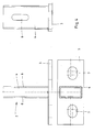
- Fig. 1 shows an embodiment of a force transmission member according to the invention in a perspective view.
- This device can be used for example as a tie rod for creasing tracks.
- the device comprises a rod 1 and two end pieces 2.
- the rod 1 is formed as an elongate, rectangular in cross section rod body.
- the end pieces 2 are each arranged at the end of the rod 1. For this purpose, the end pieces 2 are each pushed onto the rod 1.
- the rod 1 is formed of a glass fiber reinforced plastic.
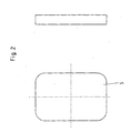
- Fig. 3 shows the rod 1 of the device according to Fig. 1 in detail.
- the rod 1 has a length which exceeds the width of the rod 1 by a factor of approximately 30.
- the rod 1 is rectangular in cross-section.
- the rod 1 has recesses 6 in the region of its two ends.
- the region of the ends of the rod 1 is that region which is inserted in the sleeve 4 when properly connected to a sleeve 4.
- the rod 1 has in the region of each end 2 recesses 6, which are arranged on opposite large surfaces of the rod 1.
- the rod 1 can thereby be connected either in any orientation with the sleeve 4, or it can be made a connection with the sleeve 4 at two points.
- the recesses 6 have a rectangular base.
- the recesses 6 extend into the rod 1 inside.
- the depth of the recesses 6 may amount to approximately one third of the thickness of the rod 1.
- Fig. 4 shows an embodiment of an end piece 2 according to the invention.
- This consists of the sleeve 4 on the one hand and the flange 3 on the other.
- the flange 3 serves to connect to a tensile and compressive force source.
- This may be, for example, the rail of a track.
- the flange 3 has bores 7, through which corresponding connecting means such as screws, bolts, rivets and the like can be guided.
Claims (15)
- Organe de transmission de puissance électriquement isolant et destiné à absorber les forces de traction et de pression, comprenant une barre (1), une pièce d'extrémité (2) destinée à être raccordée à une source de forces de traction et de pression étant disposée à l'au moins une extrémité de la barre (1), caractérisé en ce qu'au niveau de sa surface d'enveloppe, la barre (1) comprend un évidement (6) servant de cavité creusée, une plaque de fixation (5) étant insérée avec un engagement positif dans le dit évidement (6), et que la barre (1) introduite dans une gaine (4) de la pièce d'extrémité (2) est reliée à engagement positif à la pièce d'extrémité (2) par moyen d'une liaison inamovible entre la plaque de fixation (5), d'une part, et la gaine (4), d'autre part.
- Organe de transmission de puissance selon la revendication 1, caractérisé en ce que la barre (1), d'une part, et la pièce d'extrémité (2), d'autre part, sont constituées de matériaux différents.
- Organe de transmission de puissance selon l'une des revendications précédentes, caractérisé en ce que la barre (1) est constituée d'un matériau électriquement isolant.
- Organe de transmission de puissance selon l'une des revendications précédentes, caractérisé en ce que la pièce d'extrémité (2) et/ou la plaque de fixation (5) est constituée d'acier.
- Organe de transmission de puissance selon l'une des revendications précédentes, caractérisé en ce que la barre (1) est constituée de plastique ou d'un plastique renforcé par des fibres de verre.
- Organe de transmission de puissance selon l'une des revendications précédentes, caractérisé en ce que la barre (1) comprend une résistance électrique de 1 Ohm par 1 cm dans la direction de l'extension longitudinale de celle-ci.
- Organe de transmission de puissance selon l'une des revendications précédentes, caractérisé en ce qu'un boîtier (10) est disposé sur la pièce d'extrémité (2), lequel boîtier comprend des éléments de connexion électriques.
- Organe de transmission de puissance selon l'une des revendications précédentes, caractérisé en ce que la barre (1) comprend un conducteur électrique (11) disposé à l'intérieur de celle-ci dans la direction longitudinale et électriquement isolé par rapport à la pièce d'extrémité (2).
- Utilisation d'un membre de transmission de puissance selon l'une des revendications précédentes en tant que tringle d'écartement pour des rails rainurées.
- Procédé de fabrication d'un organe de transmission de puissance électriquement isolant et destiné à absorber des forces de traction et de pression, caractérisé en ce qu'un évidement (6) servant de cavité creusée est formé dans la surface d'enveloppe d'une barre (1), une plaque de fixation (5) étant insérée avec un engagement positif dans l'évidement (6), la barre (1) étant ensuite introduite dans une gaine (4) d'une pièce d'extrémité (2) pour être raccordée à une source de forces de traction et de pression, et la plaque de fixation (5) étant ensuite reliée de manière inamovible à la gaine (4), de sorte que la pièce d'extrémité (2) est relié par engagement positif à la barre (1).
- Procédé selon la revendication 10, caractérisé en ce que la plaque de fixation (5) est soudée, notamment soudée par laser à la gaine (4).
- Procédé selon l'une des revendications 10 ou 11, caractérisé en ce que l'évidement (6) est formé dans la barre (1) par usinage avec enlèvement de copeaux, notamment par fraisage.
- Procédé selon l'une des revendications 10 à 12, caractérisé en ce que la barre (1) est constituée de façon à être électriquement isolante.
- Procédé selon l'une des revendications 10 à 13, caractérisé en ce que la barre (1) est formée en matière plastique.
- Procédé selon l'une des revendications 10 à 14, caractérisé en ce que la pièce d'extrémité (2) et/ou la plaque de fixation (5) est formée en acier.
Priority Applications (1)
| Application Number | Priority Date | Filing Date | Title |
|---|---|---|---|
| EP13155982.5A EP2770106B1 (fr) | 2013-02-20 | 2013-02-20 | Organe de transmission de puissance électriquement isolant pour absorber les forces de traction et de pression et procédé de fabrication de celui-ci |
Applications Claiming Priority (1)
| Application Number | Priority Date | Filing Date | Title |
|---|---|---|---|
| EP13155982.5A EP2770106B1 (fr) | 2013-02-20 | 2013-02-20 | Organe de transmission de puissance électriquement isolant pour absorber les forces de traction et de pression et procédé de fabrication de celui-ci |
Publications (2)
| Publication Number | Publication Date |
|---|---|
| EP2770106A1 EP2770106A1 (fr) | 2014-08-27 |
| EP2770106B1 true EP2770106B1 (fr) | 2015-07-01 |
Family
ID=47779849
Family Applications (1)
| Application Number | Title | Priority Date | Filing Date |
|---|---|---|---|
| EP13155982.5A Not-in-force EP2770106B1 (fr) | 2013-02-20 | 2013-02-20 | Organe de transmission de puissance électriquement isolant pour absorber les forces de traction et de pression et procédé de fabrication de celui-ci |
Country Status (1)
| Country | Link |
|---|---|
| EP (1) | EP2770106B1 (fr) |
Families Citing this family (1)
| Publication number | Priority date | Publication date | Assignee | Title |
|---|---|---|---|---|
| CN108221514B (zh) * | 2018-01-10 | 2019-05-17 | 邢义军 | 一种铁轨及其轨距调整器 |
Family Cites Families (4)
| Publication number | Priority date | Publication date | Assignee | Title |
|---|---|---|---|---|
| GB113773A (fr) * | ||||
| DE813039C (de) * | 1949-02-10 | 1951-09-06 | Dortmunder Stadtwerke A G | Spurstange fuer Strassen- und Kleinbahnen |
| DE8526882U1 (de) * | 1985-09-20 | 1985-11-14 | Gutzeit, Klaus, 5064 Rösrath | Isolierte Spurstange für Bahngleise |
| DE19843375C2 (de) * | 1998-09-10 | 2003-02-13 | Sedra Asphalt Technik Biebrich | Isolierende Ummantelung für Spurstangen |
-
2013
- 2013-02-20 EP EP13155982.5A patent/EP2770106B1/fr not_active Not-in-force
Also Published As
| Publication number | Publication date |
|---|---|
| EP2770106A1 (fr) | 2014-08-27 |
Similar Documents
| Publication | Publication Date | Title |
|---|---|---|
| EP2441129B1 (fr) | Contact à insérer pour relier un composant électronique à une carte de circuits imprimés ainsi qu'outil d'insertion et procédé pour fabriquer un contact à insérer | |
| DE102012110098B4 (de) | Verfahren zur Herstellung elektrischer Durchführungen | |
| EP0945919A1 (fr) | Méthode de fixation d'un contact électrique permanent à la traverse d'un rail de chemin de fer et le contact correspondant | |
| EP3339633A1 (fr) | Procédé de fabrication d'une liaison équipotentielle sur une pale de rotor d'éolienne et pale de rotor d'éolienne comprenant une liaison équipotentielle | |
| EP3339632B1 (fr) | Unité de raccordement et de fixation pour un récepteur d'éclairs à intégrer dans une pale de rotor d'éolienne | |
| DE102013111963A1 (de) | Plattenelement mit Tiefziehbohrung für Einpresskontakte | |
| EP2770106B1 (fr) | Organe de transmission de puissance électriquement isolant pour absorber les forces de traction et de pression et procédé de fabrication de celui-ci | |
| DE102012222364A1 (de) | Steckverbinder und Vorrichtung mit einem solchen Steckverbinder | |
| DE202009017984U1 (de) | Einpressverbinder | |
| WO2009109481A2 (fr) | Composant comportant un insert de paroi | |
| DE202012012274U1 (de) | Temperaturmessanordnung | |
| DE2223892A1 (de) | Verfahren zum herstellen von elektrischen stromleiterplatten | |
| DE3709443C2 (fr) | ||
| DE102007050239A1 (de) | Verfahren zum Abisolieren eines Flachbandkabels an seinem freien Ende bzw. innerhalb des Flachbandkabels | |
| DE102014107491B4 (de) | Verfahren zur Herstellung eines Kabelschuhs | |
| DE102018117597A1 (de) | Verlorenes Bohrgestänge | |
| EP2607859A2 (fr) | Corps de support destiné à la réception d'un capteur | |
| EP2463080B1 (fr) | Elément de chauffage, procédé de soudage de composants en matière synthétique tubulaires avec un élément de chauffage et système constitué de composants tubulaires et d'un élément de chauffage | |
| EP2948687B1 (fr) | Filetage | |
| DE3516532A1 (de) | Verfahren und vorrichtung zum festlegen eines kontaktstifts im isolierkoerper eines steckverbinders und nach diesem verfahren hergestellter steckverbinder | |
| EP3342008A1 (fr) | Procédé de fabrication d'une connexion enfichable, procédé de renforcement d'une connexion enfichable et dispositif associé | |
| DE102022124222A1 (de) | Verfahren, Verbindungsanordnung und Verwendung einer Verbindungsanordnung für zumindest zwei Litzenleitungen | |
| WO2015165720A1 (fr) | Connecteur pour câbles électriques | |
| DE102022204275A1 (de) | Stromtragende Leistungselektronikanbindungsvorrichtung und Verfahren zum Herstellen einer derartigen Leistungselektronikanbindungsvorrichtung | |
| DE102010018059A1 (de) | Transformator |
Legal Events
| Date | Code | Title | Description |
|---|---|---|---|
| PUAI | Public reference made under article 153(3) epc to a published international application that has entered the european phase |
Free format text: ORIGINAL CODE: 0009012 |
|
| 17P | Request for examination filed |
Effective date: 20130803 |
|
| AK | Designated contracting states |
Kind code of ref document: A1 Designated state(s): AL AT BE BG CH CY CZ DE DK EE ES FI FR GB GR HR HU IE IS IT LI LT LU LV MC MK MT NL NO PL PT RO RS SE SI SK SM TR |
|
| AX | Request for extension of the european patent |
Extension state: BA ME |
|
| GRAP | Despatch of communication of intention to grant a patent |
Free format text: ORIGINAL CODE: EPIDOSNIGR1 |
|
| INTG | Intention to grant announced |
Effective date: 20150220 |
|
| GRAS | Grant fee paid |
Free format text: ORIGINAL CODE: EPIDOSNIGR3 |
|
| GRAA | (expected) grant |
Free format text: ORIGINAL CODE: 0009210 |
|
| AK | Designated contracting states |
Kind code of ref document: B1 Designated state(s): AL AT BE BG CH CY CZ DE DK EE ES FI FR GB GR HR HU IE IS IT LI LT LU LV MC MK MT NL NO PL PT RO RS SE SI SK SM TR |
|
| REG | Reference to a national code |
Ref country code: GB Ref legal event code: FG4D Free format text: NOT ENGLISH |
|
| REG | Reference to a national code |
Ref country code: AT Ref legal event code: REF Ref document number: 734041 Country of ref document: AT Kind code of ref document: T Effective date: 20150715 Ref country code: CH Ref legal event code: EP Ref country code: CH Ref legal event code: NV Representative=s name: E. BLUM AND CO. AG PATENT- UND MARKENANWAELTE , CH |
|
| REG | Reference to a national code |
Ref country code: IE Ref legal event code: FG4D Free format text: LANGUAGE OF EP DOCUMENT: GERMAN |
|
| REG | Reference to a national code |
Ref country code: DE Ref legal event code: R096 Ref document number: 502013000789 Country of ref document: DE |
|
| REG | Reference to a national code |
Ref country code: NL Ref legal event code: FP |
|
| REG | Reference to a national code |
Ref country code: LT Ref legal event code: MG4D |
|
| PG25 | Lapsed in a contracting state [announced via postgrant information from national office to epo] |
Ref country code: LV Free format text: LAPSE BECAUSE OF FAILURE TO SUBMIT A TRANSLATION OF THE DESCRIPTION OR TO PAY THE FEE WITHIN THE PRESCRIBED TIME-LIMIT Effective date: 20150701 Ref country code: NO Free format text: LAPSE BECAUSE OF FAILURE TO SUBMIT A TRANSLATION OF THE DESCRIPTION OR TO PAY THE FEE WITHIN THE PRESCRIBED TIME-LIMIT Effective date: 20151001 Ref country code: LT Free format text: LAPSE BECAUSE OF FAILURE TO SUBMIT A TRANSLATION OF THE DESCRIPTION OR TO PAY THE FEE WITHIN THE PRESCRIBED TIME-LIMIT Effective date: 20150701 Ref country code: FI Free format text: LAPSE BECAUSE OF FAILURE TO SUBMIT A TRANSLATION OF THE DESCRIPTION OR TO PAY THE FEE WITHIN THE PRESCRIBED TIME-LIMIT Effective date: 20150701 Ref country code: GR Free format text: LAPSE BECAUSE OF FAILURE TO SUBMIT A TRANSLATION OF THE DESCRIPTION OR TO PAY THE FEE WITHIN THE PRESCRIBED TIME-LIMIT Effective date: 20151002 |
|
| PG25 | Lapsed in a contracting state [announced via postgrant information from national office to epo] |
Ref country code: PL Free format text: LAPSE BECAUSE OF FAILURE TO SUBMIT A TRANSLATION OF THE DESCRIPTION OR TO PAY THE FEE WITHIN THE PRESCRIBED TIME-LIMIT Effective date: 20150701 Ref country code: IS Free format text: LAPSE BECAUSE OF FAILURE TO SUBMIT A TRANSLATION OF THE DESCRIPTION OR TO PAY THE FEE WITHIN THE PRESCRIBED TIME-LIMIT Effective date: 20151101 Ref country code: RS Free format text: LAPSE BECAUSE OF FAILURE TO SUBMIT A TRANSLATION OF THE DESCRIPTION OR TO PAY THE FEE WITHIN THE PRESCRIBED TIME-LIMIT Effective date: 20150701 Ref country code: ES Free format text: LAPSE BECAUSE OF FAILURE TO SUBMIT A TRANSLATION OF THE DESCRIPTION OR TO PAY THE FEE WITHIN THE PRESCRIBED TIME-LIMIT Effective date: 20150701 Ref country code: SE Free format text: LAPSE BECAUSE OF FAILURE TO SUBMIT A TRANSLATION OF THE DESCRIPTION OR TO PAY THE FEE WITHIN THE PRESCRIBED TIME-LIMIT Effective date: 20150701 Ref country code: HR Free format text: LAPSE BECAUSE OF FAILURE TO SUBMIT A TRANSLATION OF THE DESCRIPTION OR TO PAY THE FEE WITHIN THE PRESCRIBED TIME-LIMIT Effective date: 20150701 Ref country code: PT Free format text: LAPSE BECAUSE OF FAILURE TO SUBMIT A TRANSLATION OF THE DESCRIPTION OR TO PAY THE FEE WITHIN THE PRESCRIBED TIME-LIMIT Effective date: 20151102 |
|
| REG | Reference to a national code |
Ref country code: DE Ref legal event code: R097 Ref document number: 502013000789 Country of ref document: DE |
|
| PG25 | Lapsed in a contracting state [announced via postgrant information from national office to epo] |
Ref country code: DK Free format text: LAPSE BECAUSE OF FAILURE TO SUBMIT A TRANSLATION OF THE DESCRIPTION OR TO PAY THE FEE WITHIN THE PRESCRIBED TIME-LIMIT Effective date: 20150701 Ref country code: SK Free format text: LAPSE BECAUSE OF FAILURE TO SUBMIT A TRANSLATION OF THE DESCRIPTION OR TO PAY THE FEE WITHIN THE PRESCRIBED TIME-LIMIT Effective date: 20150701 Ref country code: EE Free format text: LAPSE BECAUSE OF FAILURE TO SUBMIT A TRANSLATION OF THE DESCRIPTION OR TO PAY THE FEE WITHIN THE PRESCRIBED TIME-LIMIT Effective date: 20150701 Ref country code: IT Free format text: LAPSE BECAUSE OF FAILURE TO SUBMIT A TRANSLATION OF THE DESCRIPTION OR TO PAY THE FEE WITHIN THE PRESCRIBED TIME-LIMIT Effective date: 20150701 Ref country code: CZ Free format text: LAPSE BECAUSE OF FAILURE TO SUBMIT A TRANSLATION OF THE DESCRIPTION OR TO PAY THE FEE WITHIN THE PRESCRIBED TIME-LIMIT Effective date: 20150701 |
|
| PLBE | No opposition filed within time limit |
Free format text: ORIGINAL CODE: 0009261 |
|
| STAA | Information on the status of an ep patent application or granted ep patent |
Free format text: STATUS: NO OPPOSITION FILED WITHIN TIME LIMIT |
|
| PG25 | Lapsed in a contracting state [announced via postgrant information from national office to epo] |
Ref country code: RO Free format text: LAPSE BECAUSE OF FAILURE TO SUBMIT A TRANSLATION OF THE DESCRIPTION OR TO PAY THE FEE WITHIN THE PRESCRIBED TIME-LIMIT Effective date: 20150701 |
|
| 26N | No opposition filed |
Effective date: 20160404 |
|
| PG25 | Lapsed in a contracting state [announced via postgrant information from national office to epo] |
Ref country code: SI Free format text: LAPSE BECAUSE OF FAILURE TO SUBMIT A TRANSLATION OF THE DESCRIPTION OR TO PAY THE FEE WITHIN THE PRESCRIBED TIME-LIMIT Effective date: 20150701 |
|
| PG25 | Lapsed in a contracting state [announced via postgrant information from national office to epo] |
Ref country code: MC Free format text: LAPSE BECAUSE OF FAILURE TO SUBMIT A TRANSLATION OF THE DESCRIPTION OR TO PAY THE FEE WITHIN THE PRESCRIBED TIME-LIMIT Effective date: 20150701 Ref country code: LU Free format text: LAPSE BECAUSE OF FAILURE TO SUBMIT A TRANSLATION OF THE DESCRIPTION OR TO PAY THE FEE WITHIN THE PRESCRIBED TIME-LIMIT Effective date: 20160220 |
|
| REG | Reference to a national code |
Ref country code: FR Ref legal event code: ST Effective date: 20161028 |
|
| REG | Reference to a national code |
Ref country code: IE Ref legal event code: MM4A |
|
| PG25 | Lapsed in a contracting state [announced via postgrant information from national office to epo] |
Ref country code: IE Free format text: LAPSE BECAUSE OF NON-PAYMENT OF DUE FEES Effective date: 20160220 Ref country code: FR Free format text: LAPSE BECAUSE OF NON-PAYMENT OF DUE FEES Effective date: 20160229 |
|
| PG25 | Lapsed in a contracting state [announced via postgrant information from national office to epo] |
Ref country code: MT Free format text: LAPSE BECAUSE OF FAILURE TO SUBMIT A TRANSLATION OF THE DESCRIPTION OR TO PAY THE FEE WITHIN THE PRESCRIBED TIME-LIMIT Effective date: 20150701 |
|
| GBPC | Gb: european patent ceased through non-payment of renewal fee |
Effective date: 20170220 |
|
| REG | Reference to a national code |
Ref country code: DE Ref legal event code: R082 Ref document number: 502013000789 Country of ref document: DE Representative=s name: RAUSCH WANISCHECK-BERGMANN BRINKMANN PARTNERSC, DE |
|
| PG25 | Lapsed in a contracting state [announced via postgrant information from national office to epo] |
Ref country code: GB Free format text: LAPSE BECAUSE OF NON-PAYMENT OF DUE FEES Effective date: 20170220 |
|
| PG25 | Lapsed in a contracting state [announced via postgrant information from national office to epo] |
Ref country code: SM Free format text: LAPSE BECAUSE OF FAILURE TO SUBMIT A TRANSLATION OF THE DESCRIPTION OR TO PAY THE FEE WITHIN THE PRESCRIBED TIME-LIMIT Effective date: 20150701 Ref country code: CY Free format text: LAPSE BECAUSE OF FAILURE TO SUBMIT A TRANSLATION OF THE DESCRIPTION OR TO PAY THE FEE WITHIN THE PRESCRIBED TIME-LIMIT Effective date: 20150701 Ref country code: HU Free format text: LAPSE BECAUSE OF FAILURE TO SUBMIT A TRANSLATION OF THE DESCRIPTION OR TO PAY THE FEE WITHIN THE PRESCRIBED TIME-LIMIT; INVALID AB INITIO Effective date: 20130220 |
|
| PG25 | Lapsed in a contracting state [announced via postgrant information from national office to epo] |
Ref country code: MK Free format text: LAPSE BECAUSE OF FAILURE TO SUBMIT A TRANSLATION OF THE DESCRIPTION OR TO PAY THE FEE WITHIN THE PRESCRIBED TIME-LIMIT Effective date: 20150701 Ref country code: TR Free format text: LAPSE BECAUSE OF FAILURE TO SUBMIT A TRANSLATION OF THE DESCRIPTION OR TO PAY THE FEE WITHIN THE PRESCRIBED TIME-LIMIT Effective date: 20150701 |
|
| PG25 | Lapsed in a contracting state [announced via postgrant information from national office to epo] |
Ref country code: BG Free format text: LAPSE BECAUSE OF FAILURE TO SUBMIT A TRANSLATION OF THE DESCRIPTION OR TO PAY THE FEE WITHIN THE PRESCRIBED TIME-LIMIT Effective date: 20150701 |
|
| PG25 | Lapsed in a contracting state [announced via postgrant information from national office to epo] |
Ref country code: AL Free format text: LAPSE BECAUSE OF FAILURE TO SUBMIT A TRANSLATION OF THE DESCRIPTION OR TO PAY THE FEE WITHIN THE PRESCRIBED TIME-LIMIT Effective date: 20150701 |
|
| PGFP | Annual fee paid to national office [announced via postgrant information from national office to epo] |
Ref country code: NL Payment date: 20190227 Year of fee payment: 7 |
|
| PGFP | Annual fee paid to national office [announced via postgrant information from national office to epo] |
Ref country code: CH Payment date: 20190320 Year of fee payment: 7 |
|
| PGFP | Annual fee paid to national office [announced via postgrant information from national office to epo] |
Ref country code: AT Payment date: 20190228 Year of fee payment: 7 Ref country code: BE Payment date: 20190227 Year of fee payment: 7 |
|
| PGFP | Annual fee paid to national office [announced via postgrant information from national office to epo] |
Ref country code: DE Payment date: 20190426 Year of fee payment: 7 |
|
| REG | Reference to a national code |
Ref country code: DE Ref legal event code: R119 Ref document number: 502013000789 Country of ref document: DE |
|
| REG | Reference to a national code |
Ref country code: CH Ref legal event code: PL |
|
| REG | Reference to a national code |
Ref country code: NL Ref legal event code: MM Effective date: 20200301 |
|
| REG | Reference to a national code |
Ref country code: AT Ref legal event code: MM01 Ref document number: 734041 Country of ref document: AT Kind code of ref document: T Effective date: 20200220 |
|
| REG | Reference to a national code |
Ref country code: BE Ref legal event code: MM Effective date: 20200229 |
|
| PG25 | Lapsed in a contracting state [announced via postgrant information from national office to epo] |
Ref country code: AT Free format text: LAPSE BECAUSE OF NON-PAYMENT OF DUE FEES Effective date: 20200220 Ref country code: LI Free format text: LAPSE BECAUSE OF NON-PAYMENT OF DUE FEES Effective date: 20200229 Ref country code: CH Free format text: LAPSE BECAUSE OF NON-PAYMENT OF DUE FEES Effective date: 20200229 |
|
| PG25 | Lapsed in a contracting state [announced via postgrant information from national office to epo] |
Ref country code: NL Free format text: LAPSE BECAUSE OF NON-PAYMENT OF DUE FEES Effective date: 20200301 |
|
| PG25 | Lapsed in a contracting state [announced via postgrant information from national office to epo] |
Ref country code: DE Free format text: LAPSE BECAUSE OF NON-PAYMENT OF DUE FEES Effective date: 20200901 |
|
| PG25 | Lapsed in a contracting state [announced via postgrant information from national office to epo] |
Ref country code: BE Free format text: LAPSE BECAUSE OF NON-PAYMENT OF DUE FEES Effective date: 20200229 |