EP0945919A1 - Méthode de fixation d'un contact électrique permanent à la traverse d'un rail de chemin de fer et le contact correspondant - Google Patents
Méthode de fixation d'un contact électrique permanent à la traverse d'un rail de chemin de fer et le contact correspondant Download PDFInfo
- Publication number
- EP0945919A1 EP0945919A1 EP98105145A EP98105145A EP0945919A1 EP 0945919 A1 EP0945919 A1 EP 0945919A1 EP 98105145 A EP98105145 A EP 98105145A EP 98105145 A EP98105145 A EP 98105145A EP 0945919 A1 EP0945919 A1 EP 0945919A1
- Authority
- EP
- European Patent Office
- Prior art keywords
- cylindrical sleeve
- recess
- electrical contact
- cover
- sleeve
- Prior art date
- Legal status (The legal status is an assumption and is not a legal conclusion. Google has not performed a legal analysis and makes no representation as to the accuracy of the status listed.)
- Granted
Links
Images


Classifications
-
- H—ELECTRICITY
- H01—ELECTRIC ELEMENTS
- H01R—ELECTRICALLY-CONDUCTIVE CONNECTIONS; STRUCTURAL ASSOCIATIONS OF A PLURALITY OF MUTUALLY-INSULATED ELECTRICAL CONNECTING ELEMENTS; COUPLING DEVICES; CURRENT COLLECTORS
- H01R4/00—Electrically-conductive connections between two or more conductive members in direct contact, i.e. touching one another; Means for effecting or maintaining such contact; Electrically-conductive connections having two or more spaced connecting locations for conductors and using contact members penetrating insulation
- H01R4/28—Clamped connections, spring connections
- H01R4/50—Clamped connections, spring connections utilising a cam, wedge, cone or ball also combined with a screw
- H01R4/5016—Clamped connections, spring connections utilising a cam, wedge, cone or ball also combined with a screw using a cone
-
- H—ELECTRICITY
- H01—ELECTRIC ELEMENTS
- H01R—ELECTRICALLY-CONDUCTIVE CONNECTIONS; STRUCTURAL ASSOCIATIONS OF A PLURALITY OF MUTUALLY-INSULATED ELECTRICAL CONNECTING ELEMENTS; COUPLING DEVICES; CURRENT COLLECTORS
- H01R4/00—Electrically-conductive connections between two or more conductive members in direct contact, i.e. touching one another; Means for effecting or maintaining such contact; Electrically-conductive connections having two or more spaced connecting locations for conductors and using contact members penetrating insulation
- H01R4/58—Electrically-conductive connections between two or more conductive members in direct contact, i.e. touching one another; Means for effecting or maintaining such contact; Electrically-conductive connections having two or more spaced connecting locations for conductors and using contact members penetrating insulation characterised by the form or material of the contacting members
- H01R4/64—Connections between or with conductive parts having primarily a non-electric function, e.g. frame, casing, rail
-
- H—ELECTRICITY
- H01—ELECTRIC ELEMENTS
- H01R—ELECTRICALLY-CONDUCTIVE CONNECTIONS; STRUCTURAL ASSOCIATIONS OF A PLURALITY OF MUTUALLY-INSULATED ELECTRICAL CONNECTING ELEMENTS; COUPLING DEVICES; CURRENT COLLECTORS
- H01R4/00—Electrically-conductive connections between two or more conductive members in direct contact, i.e. touching one another; Means for effecting or maintaining such contact; Electrically-conductive connections having two or more spaced connecting locations for conductors and using contact members penetrating insulation
- H01R4/28—Clamped connections, spring connections
- H01R4/30—Clamped connections, spring connections utilising a screw or nut clamping member
Definitions
- the above invention relates to a method for Production of a permanent, electrical contact on the bridge a railway track, under the provision of a Through hole in the bar of the rail and inserting a Sleeve of electrically conductive material with a Through hole.
- the invention further relates to a permanent, electrical Contact made with the method and from a a through-hole having sleeve, the on one end has a collar and made of electrically conductive Material exists.
- the displaced in a known manner material thus forms none Surface used for making an electrical contact would be suitable because this displaced during the drawing process Material is deposited irregularly at the web of the rail.
- the object of the above invention is to provide the abovementioned To avoid disadvantages of the prior art and a To propose method as well as a device that it allows for a permanent, electrical contact for electrical connections on both Sides of the bridge of a rail body is usable and at the same time excellent and constant, electric and having mechanical features.
- This object is achieved with a method for producing a permanent, electrical contact on the bridge of a Rail body achieved in that in the web of the Rail body is inserted through a through hole and in this through hole a cylindrical, with a Through hole provided sleeve, which is inserted one end has a contact flange, with one side the web of the rail body is in communication, the Method characterized in that on the Investment flange opposite side of the rail web, on free end of the cylindrical sleeve, a lid arranged which, on its side facing the sleeve, becomes one Has recess that the through hole of the cylindrical sleeve an expansion-pulling operation is subjected to and a displacement of a part of the Through hole limiting material takes place and the during the drawing process displaced material in the Recess of the lid is introduced and this Material accumulation on the walls of the recess to the plant is brought.
- the lid has an opening which is larger than the maximum diameter of the Drawing tool.
- the inner recess of the lid a undercut, by 10 ° with respect to the longitudinal axis of the lid inclined peripheral wall on.
- this is Lid made of a copper alloy, the very good electrical conductivity and increased mechanical Resistant.
- the lid and the cylindrical sleeve made of materials that the have the same coefficient of thermal expansion.
- cylindrical sleeve and the lid with a Coated tin layer.
- the bridge of the rail body is not excessive weakened and can be used safely take up.
- the different amounts of during the drawing process displaced and out of the through hole of the cylindrical Sleeve can absorb escaping material.
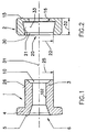
- Figures 1 and 2 is a cylindrical sleeve as well a lid attached to the free end of the sleeve is shown.
- the cylindrical sleeve 1 has a cylindrical piece 3.
- the cylindrical sleeve 1 has a molded flange 4 on, as a contact flange and as electrical contact is formed.
- the cylindrical sleeve 1 is in the axial direction of a Drilled hole 102.
- the flange 4 On the outside, the flange 4 has a slight crown trained area 5 on.
- the flange 4 of the cylindrical sleeve 1 has a Recess 6, which is suitable, the head of a To take drawing tool 7, with the pulling of the cylindrical sleeve 3 of the component 1 takes place ( Figure 4).
- the free end of the cylindrical sleeve 3 also has its front end a recess 10, the is suitable, the resulting during the drawing process Material wall record.
- the recess 10 has in an advantageous manner frustoconical shape.
- the end cover 2 has on one side a flat surface 15 on to create an electrical contact surface.
- the bore 16 of the lid 2 has a diameter which greater than the maximum cross section of the pulling head 7 is.
- the Lid 2 also has an internal recess 20.
- the inner recess 20 conical and is formed by a circumferential wall limited, which forms an undercut.
- the inlet 21 of the recess 26 has a diameter 22 on slightly larger than the 25th diameter cylindrical sleeve 3 is.
- the dimensions 22 of the entrance 21 of the inner recess 20 coincident with the Diameter 27 of the bore 28 is selected.
- these holes 28 is the cylindrical sleeve 3 of the part 1 for the Production of a permanent, electrical contact on the bridge used a rail track.
- the inner recess 20 has a peripheral wall 30 which inclined by about 10 ° relative to the axis 31 of the cover is.
- the inner recess 20 has a depth 32, the is sufficient to a chamber 33 inside the lid 2 limit.
- the chamber is designed so that they have a the largest possible amount of material during the drawing process the cylindrical sleeve 1 is displaced, can accommodate.
- the cylindrical sleeve 1 consists of electrically conductive Material, e.g. made of electrolytic copper.
- the lid 2 is made of an electrically conductive material manufactured having mechanical features that are sufficient to the pressure forces occurring during to record the drawing process.
- the lid 2 in an advantageous manner a copper alloy, e.g. Copper that with Beryllium, strontium, zirconium, nickel-silicon alloyed has been.
- a copper alloy e.g. Copper that with Beryllium, strontium, zirconium, nickel-silicon alloyed has been.
- cylindrical sleeve 1 and the lid 2 made using a material that has the same thermal expansion coefficient.
- cylindrical sleeve 1 and the cover of the second be coated with a tin layer.
- the providence of a tin layer prevents one unwanted oxidation process on parts of the electrical Contact.
- the first step in the process is to daS the web 40 of the rail body with a continuous Bore is provided. It is envisaged that the Diameter of the drilling tool slightly larger than the Dimensions 25 of the circumferential shell 26 of the cylindrical Sleeve 3 is.
- This caliber has a decent design and is together with the mounting device, not shown delivered.
- the calibrated head 7 of the drawing tool is in the Through hole 102 of the cylindrical sleeve 1 of the Side of the abutment flange 4 used.
- An extension of the calibrated head of the drawing tool 7 occurs after insertion into the through bore 102 of the sleeve 1 on the side opposite the bottle 4 side of the sleeve this one off.
- the inner recess 20 of the lid 2 is on the web 40 of the rail body directed (arrow 42).
- the cover 2 is in abutment with the web 40 of the Rail body held.
- the conical section 43 of Pulling head 7 brings during the expansion pulling the Sleeve 1 derenn outer jacket 26 in non-positive Connection with the wall of the bore 28, creating a excellent, lasting, electrical contact created becomes.
- the figure 6 can be seen that in an advantageous Way, using an electrical contact, one Arrangement on webs of rail bodies with different Thickness 100, 101 is possible.
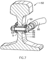
- the figure 7 and 8 can be taken as two electrical Ladder 50 with its connection shoes 51 on both sides of the Rail body 52 footbridge 40, using a single sleeve 1, to be mounted.
- both cable lugs are under Use a single screw 55 mounted and fixed braced.
Landscapes
- Insulating Bodies (AREA)
- Insulators (AREA)
- Near-Field Transmission Systems (AREA)
- Connections Effected By Soldering, Adhesion, Or Permanent Deformation (AREA)
- Machines For Laying And Maintaining Railways (AREA)
- Train Traffic Observation, Control, And Security (AREA)
Priority Applications (4)
| Application Number | Priority Date | Filing Date | Title |
|---|---|---|---|
| AT98105145T ATE315838T1 (de) | 1998-03-22 | 1998-03-22 | Verfahren zur herstellung eines elektrischen dauerkontaktes am steg einer eisenbahnschiene und mit dem verfahren hergestellter elektrischer dauerkontakt |
| EP98105145A EP0945919B1 (fr) | 1998-03-22 | 1998-03-22 | Méthode de fixation d'un contact électrique permanent à la traverse d'un rail de chemin de fer et le contact correspondant |
| DE59813339T DE59813339D1 (de) | 1998-03-22 | 1998-03-22 | Verfahren zur Herstellung eines elektrischen Dauerkontaktes am Steg einer Eisenbahnschiene und mit dem Verfahren hergestellter elektrischer Dauerkontakt |
| ES98105145T ES2256901T3 (es) | 1998-03-22 | 1998-03-22 | Procedimiento para establecer un contacto electrico permanente en el alma de un rail ferroviario y contacto electrico permanente obtenido con dicho procedimiento. |
Applications Claiming Priority (1)
| Application Number | Priority Date | Filing Date | Title |
|---|---|---|---|
| EP98105145A EP0945919B1 (fr) | 1998-03-22 | 1998-03-22 | Méthode de fixation d'un contact électrique permanent à la traverse d'un rail de chemin de fer et le contact correspondant |
Publications (2)
| Publication Number | Publication Date |
|---|---|
| EP0945919A1 true EP0945919A1 (fr) | 1999-09-29 |
| EP0945919B1 EP0945919B1 (fr) | 2006-01-11 |
Family
ID=8231632
Family Applications (1)
| Application Number | Title | Priority Date | Filing Date |
|---|---|---|---|
| EP98105145A Expired - Lifetime EP0945919B1 (fr) | 1998-03-22 | 1998-03-22 | Méthode de fixation d'un contact électrique permanent à la traverse d'un rail de chemin de fer et le contact correspondant |
Country Status (4)
| Country | Link |
|---|---|
| EP (1) | EP0945919B1 (fr) |
| AT (1) | ATE315838T1 (fr) |
| DE (1) | DE59813339D1 (fr) |
| ES (1) | ES2256901T3 (fr) |
Cited By (12)
| Publication number | Priority date | Publication date | Assignee | Title |
|---|---|---|---|---|
| EP1166951A1 (fr) * | 2000-06-26 | 2002-01-02 | Fatigue Technology, Inc. | Douilles à bride double et procédés d' assemblage |
| WO2006057592A1 (fr) * | 2004-11-26 | 2006-06-01 | Safetrack Infrasystems Sisab Ab | Methode et dispositif pour relier un conducteur electrique a une barre metallique, et outil pour fixer une bague dans un orifice de barre metallique |
| EP1779964A1 (fr) * | 2005-10-28 | 2007-05-02 | Fatigue Technology, Inc. | Douille à déplacement radial pour retenir un membre par rapport à une pièce structurale |
| WO2007127399A2 (fr) | 2006-04-27 | 2007-11-08 | Fatigue Technology, Inc. | Caractéristiques géométriques de décharge pour vague dans des éléments structuraux dilatables radialement à l'intérieur de pièces |
| FR2922370A1 (fr) * | 2007-10-15 | 2009-04-17 | Eldre Soc Par Actions Simplifi | Borne de connexion electrique. |
| WO2011072752A1 (fr) * | 2009-12-18 | 2011-06-23 | Cembre Ltd | Procédé et coffret pour l'application d'un contact électrique permanent dans l'âme d'un rail et similaire |
| ITMI20100329A1 (it) * | 2010-02-26 | 2011-08-27 | Cembre Spa | Dispositivo di tiro per tirare un punzone attraverso una bussola di contatto |
| WO2013086333A1 (fr) | 2011-12-07 | 2013-06-13 | Eldre Corporation | Appareil de traversée amovible de barre omnibus |
| ITMI20120406A1 (it) * | 2012-03-15 | 2013-09-16 | Cembre Spa | Contatto elettrico permanente applicabile sull'anima di rotaie e simili |
| US10010983B2 (en) | 2008-03-07 | 2018-07-03 | Fatigue Technology, Inc. | Expandable member with wave inhibitor and methods of using the same |
| CN109131438A (zh) * | 2018-08-27 | 2019-01-04 | 深圳市森博尔电力设备科技有限公司 | 一种铁路轨道回流系统 |
| CN109722950A (zh) * | 2019-01-14 | 2019-05-07 | 上海国爱电气有限公司 | 一种杂散电流均回流电缆专用35°角接线端子 |
Families Citing this family (13)
| Publication number | Priority date | Publication date | Assignee | Title |
|---|---|---|---|---|
| US7448652B2 (en) | 2003-07-31 | 2008-11-11 | Fatigue Technology Inc. | Tubular metal fitting expandable in a wall opening and method of installation |
| EP1803526B1 (fr) | 2005-12-28 | 2017-03-15 | Fatigue Technology, Inc. | Ensemble mandrin et procédé de son utilisation |
| US8568034B2 (en) | 2006-01-11 | 2013-10-29 | Fatigue Technology, Inc. | Bushing kits, bearings, and methods of installation |
| ATE536957T1 (de) | 2006-04-27 | 2011-12-15 | Fatigue Technology Inc | Ausrichtungsvorrichtung und anwendungsverfahren |
| US7958766B2 (en) | 2006-06-29 | 2011-06-14 | Fatigue Technology, Inc. | Self-aligning tools and a mandrel with retention sleeve |
| US8069699B2 (en) | 2006-08-28 | 2011-12-06 | Fatigue Technology, Inc. | Installation/processing systems and methods of using the same |
| EP2210001B1 (fr) | 2007-10-16 | 2017-08-02 | Fatigue Technology, Inc. | Ensemble attache expansible à collier déformé |
| US8506222B2 (en) | 2008-07-18 | 2013-08-13 | Fatigue Technology, Inc. | Nut plate assembly and methods of using the same |
| WO2010118366A1 (fr) | 2009-04-10 | 2010-10-14 | Fatigue Technology, Inc. | Ensemble apte à être installé comprenant un élément externe extensible et un dispositif de fixation avec un mandrin |
| EP2513499B1 (fr) | 2009-12-16 | 2015-04-08 | Fatigue Technology, Inc. | Ensemble plaque à écrou modulaires et procédés d'utilisation de celui-ci |
| WO2012167136A2 (fr) | 2011-06-03 | 2012-12-06 | Fatigue Technology, Inc. | Inhibiteurs de fissuration expansibles et leurs procédés d'utilisation |
| WO2012174215A2 (fr) | 2011-06-15 | 2012-12-20 | Fatigue Technology, Inc | Écrous d'ancrage modulaires avec ensembles écrous fermés |
| US10130985B2 (en) | 2012-01-30 | 2018-11-20 | Fatigue Technology, Inc. | Smart installation/processing systems, components, and methods of operating the same |
Citations (2)
| Publication number | Priority date | Publication date | Assignee | Title |
|---|---|---|---|---|
| EP0328946A2 (fr) * | 1988-02-18 | 1989-08-23 | CEMBRE S.p.A. | Contact électrique permanent applicable à un patin de rail pour équivalent |
| DE29712206U1 (de) * | 1997-07-11 | 1997-08-28 | Kabelkonfektionstechnik Kkt Gm | Vorrichtung zum Anschluß einer elektrischen Leitung an einem Eisenbahnschienensteg o.dgl. |
-
1998
- 1998-03-22 DE DE59813339T patent/DE59813339D1/de not_active Expired - Lifetime
- 1998-03-22 AT AT98105145T patent/ATE315838T1/de active
- 1998-03-22 ES ES98105145T patent/ES2256901T3/es not_active Expired - Lifetime
- 1998-03-22 EP EP98105145A patent/EP0945919B1/fr not_active Expired - Lifetime
Patent Citations (2)
| Publication number | Priority date | Publication date | Assignee | Title |
|---|---|---|---|---|
| EP0328946A2 (fr) * | 1988-02-18 | 1989-08-23 | CEMBRE S.p.A. | Contact électrique permanent applicable à un patin de rail pour équivalent |
| DE29712206U1 (de) * | 1997-07-11 | 1997-08-28 | Kabelkonfektionstechnik Kkt Gm | Vorrichtung zum Anschluß einer elektrischen Leitung an einem Eisenbahnschienensteg o.dgl. |
Cited By (29)
| Publication number | Priority date | Publication date | Assignee | Title |
|---|---|---|---|---|
| US7375277B1 (en) | 2000-06-26 | 2008-05-20 | Fatigue Technology, Inc. | Double flanged bushings and installation methods |
| US7100264B2 (en) | 2000-06-26 | 2006-09-05 | Fatigue Technology, Inc. | Method of installing double flanged bushings |
| EP1743732A2 (fr) * | 2000-06-26 | 2007-01-17 | Fatigue Technology, Inc. | Douilles à bride double et procédés d' assemblage |
| EP1743732A3 (fr) * | 2000-06-26 | 2007-03-28 | Fatigue Technology, Inc. | Douilles à bride double et procédés d' assemblage |
| EP1166951A1 (fr) * | 2000-06-26 | 2002-01-02 | Fatigue Technology, Inc. | Douilles à bride double et procédés d' assemblage |
| WO2006057592A1 (fr) * | 2004-11-26 | 2006-06-01 | Safetrack Infrasystems Sisab Ab | Methode et dispositif pour relier un conducteur electrique a une barre metallique, et outil pour fixer une bague dans un orifice de barre metallique |
| US7290334B2 (en) | 2004-11-26 | 2007-11-06 | Safetrack Infrasystems Sisab Ab | Method and device for connecting an electric conductor to a metal rail and a tool for attaching a bushing in an opening in a metal rail |
| EP1779964A1 (fr) * | 2005-10-28 | 2007-05-02 | Fatigue Technology, Inc. | Douille à déplacement radial pour retenir un membre par rapport à une pièce structurale |
| WO2007127399A3 (fr) * | 2006-04-27 | 2007-12-21 | Fatigue Technology Inc | Caractéristiques géométriques de décharge pour vague dans des éléments structuraux dilatables radialement à l'intérieur de pièces |
| WO2007127399A2 (fr) | 2006-04-27 | 2007-11-08 | Fatigue Technology, Inc. | Caractéristiques géométriques de décharge pour vague dans des éléments structuraux dilatables radialement à l'intérieur de pièces |
| US8526195B2 (en) * | 2007-10-15 | 2013-09-03 | Eldre | Electrical connection terminal |
| FR2922370A1 (fr) * | 2007-10-15 | 2009-04-17 | Eldre Soc Par Actions Simplifi | Borne de connexion electrique. |
| WO2009050170A1 (fr) * | 2007-10-15 | 2009-04-23 | Eldre | Borne de connexion électrique |
| US20100243322A1 (en) * | 2007-10-15 | 2010-09-30 | Eldre | Electrical connection terminal |
| JP2011501354A (ja) * | 2007-10-15 | 2011-01-06 | エルドール | 電気的接続端子 |
| US10010983B2 (en) | 2008-03-07 | 2018-07-03 | Fatigue Technology, Inc. | Expandable member with wave inhibitor and methods of using the same |
| WO2011072752A1 (fr) * | 2009-12-18 | 2011-06-23 | Cembre Ltd | Procédé et coffret pour l'application d'un contact électrique permanent dans l'âme d'un rail et similaire |
| US8851395B2 (en) | 2009-12-18 | 2014-10-07 | Cembre Ltd. | Method for the application of a permanent electrical contact to the web of rails |
| ITMI20100329A1 (it) * | 2010-02-26 | 2011-08-27 | Cembre Spa | Dispositivo di tiro per tirare un punzone attraverso una bussola di contatto |
| WO2013086333A1 (fr) | 2011-12-07 | 2013-06-13 | Eldre Corporation | Appareil de traversée amovible de barre omnibus |
| EP2789053A4 (fr) * | 2011-12-07 | 2015-08-12 | Eldre Corp | Appareil de traversée amovible de barre omnibus |
| US9209531B2 (en) | 2011-12-07 | 2015-12-08 | Eldre Corporation | Bus bar releasable bushing apparatus |
| ITMI20120406A1 (it) * | 2012-03-15 | 2013-09-16 | Cembre Spa | Contatto elettrico permanente applicabile sull'anima di rotaie e simili |
| EP2638981A1 (fr) * | 2012-03-15 | 2013-09-18 | CEMBRE S.p.A. | Contact électrique permanent pouvant être appliqué sur l'âme d'un rail |
| CN103311677A (zh) * | 2012-03-15 | 2013-09-18 | 塞母布雷有限公司 | 适用于导轨的腹板等的永久性电接触件及其制造方法 |
| US9142894B2 (en) | 2012-03-15 | 2015-09-22 | Cembre S.P.A. | Permanent electrical contact applicable to the web of rails and the like |
| CN103311677B (zh) * | 2012-03-15 | 2017-06-09 | 塞母布雷有限公司 | 适用于导轨的腹板等的永久性电接触件及其制造方法 |
| CN109131438A (zh) * | 2018-08-27 | 2019-01-04 | 深圳市森博尔电力设备科技有限公司 | 一种铁路轨道回流系统 |
| CN109722950A (zh) * | 2019-01-14 | 2019-05-07 | 上海国爱电气有限公司 | 一种杂散电流均回流电缆专用35°角接线端子 |
Also Published As
| Publication number | Publication date |
|---|---|
| ATE315838T1 (de) | 2006-02-15 |
| DE59813339D1 (de) | 2006-04-06 |
| ES2256901T3 (es) | 2006-07-16 |
| EP0945919B1 (fr) | 2006-01-11 |
Similar Documents
| Publication | Publication Date | Title |
|---|---|---|
| EP0945919A1 (fr) | Méthode de fixation d'un contact électrique permanent à la traverse d'un rail de chemin de fer et le contact correspondant | |
| EP3189561B1 (fr) | Contact a sertir | |
| DE102016105768B3 (de) | Elektrischer Leiter mit einer Reibschweißhülse | |
| EP0921328B1 (fr) | Douille avec une collerette médiane, son utilisation et son procédé de fabrication | |
| DE102017123864B3 (de) | Elektrische Leitungsanordnung mit Direktkontaktierung und Verfahren zu deren Herstellung | |
| DE2137990A1 (de) | Schutzeinrichtung fur elektrische Anlagen | |
| DE19735638A1 (de) | Verfahren zur Herstellung eines Kugelzapfens, sowie Kugelzapfen für ein Kugelgelenk | |
| DE3403459C2 (de) | Gleisstopfwerkzeug und Verfahren zu dessen Herstellung | |
| DE4340411A1 (de) | Kabelstecker | |
| DE102020106415B4 (de) | REIBSCHWEIßVERBINDER UND VERFAHREN ZU DESSEN HERSTELLUNG | |
| DE19520680A1 (de) | Hydraulisches Aggregat | |
| DE2726107C2 (de) | Verfahren zum Herstellen eines preßverbundenen Erzeugnisses aus mindestens zwei Metallteilen | |
| DE10215735A1 (de) | LWL-Stecker-Kabelanordnung | |
| EP2833007A1 (fr) | Liaison rotative | |
| EP0924442B1 (fr) | Coussinet et procédé de sa fabrication | |
| DE2404121A1 (de) | Verfahren zur herstellung von kugelgelenken | |
| DE102012221466A1 (de) | Bauteilverbund zwischen zwei der Stromführung dienenden Bauteilen und Verfahren zur Herstellung eines Bauteileverbunds | |
| EP2800205B1 (fr) | Broche creuse partiellement pleine | |
| DE202007016578U1 (de) | Steckerbrücke mit Steckerhohlstift | |
| DE202011110628U1 (de) | Kontaktstift | |
| DE102018115122B4 (de) | Kontaktstiftabdichtung mit thermoplastischem Elastomer | |
| DE1936422B2 (de) | Elektrische durchgangsleiter fuer eine schaltungplatte | |
| DE2940008C2 (fr) | ||
| DE102022124222A1 (de) | Verfahren, Verbindungsanordnung und Verwendung einer Verbindungsanordnung für zumindest zwei Litzenleitungen | |
| DE102020105103A1 (de) | Steckverbinder in einem Faserverbundbauteil |
Legal Events
| Date | Code | Title | Description |
|---|---|---|---|
| PUAI | Public reference made under article 153(3) epc to a published international application that has entered the european phase |
Free format text: ORIGINAL CODE: 0009012 |
|
| AK | Designated contracting states |
Kind code of ref document: A1 Designated state(s): AT BE CH DE DK ES FR GB IT LI NL PT SE |
|
| AX | Request for extension of the european patent |
Free format text: AL;LT;LV;MK;RO;SI |
|
| RTI1 | Title (correction) |
Free format text: METHOD FOR ESTABLISHING A PERMANENT ELECTRIC CONTACT TO THE WEB OF RAILS AND THE CORRESPONDING CONTACT |
|
| 17P | Request for examination filed |
Effective date: 19991115 |
|
| AKX | Designation fees paid |
Free format text: AT BE CH DE DK ES FR GB IT LI NL PT SE |
|
| GRAP | Despatch of communication of intention to grant a patent |
Free format text: ORIGINAL CODE: EPIDOSNIGR1 |
|
| GRAS | Grant fee paid |
Free format text: ORIGINAL CODE: EPIDOSNIGR3 |
|
| GRAA | (expected) grant |
Free format text: ORIGINAL CODE: 0009210 |
|
| AK | Designated contracting states |
Kind code of ref document: B1 Designated state(s): AT BE CH DE DK ES FR GB IT LI NL PT SE |
|
| REG | Reference to a national code |
Ref country code: CH Ref legal event code: EP |
|
| REF | Corresponds to: |
Ref document number: 59813339 Country of ref document: DE Date of ref document: 20060406 Kind code of ref document: P |
|
| PG25 | Lapsed in a contracting state [announced via postgrant information from national office to epo] |
Ref country code: DK Free format text: LAPSE BECAUSE OF FAILURE TO SUBMIT A TRANSLATION OF THE DESCRIPTION OR TO PAY THE FEE WITHIN THE PRESCRIBED TIME-LIMIT Effective date: 20060411 |
|
| REG | Reference to a national code |
Ref country code: CH Ref legal event code: NV Representative=s name: FREI PATENTANWALTSBUERO |
|
| REG | Reference to a national code |
Ref country code: SE Ref legal event code: TRGR |
|
| GBT | Gb: translation of ep patent filed (gb section 77(6)(a)/1977) |
Effective date: 20060420 |
|
| PG25 | Lapsed in a contracting state [announced via postgrant information from national office to epo] |
Ref country code: PT Free format text: LAPSE BECAUSE OF FAILURE TO SUBMIT A TRANSLATION OF THE DESCRIPTION OR TO PAY THE FEE WITHIN THE PRESCRIBED TIME-LIMIT Effective date: 20060612 |
|
| REG | Reference to a national code |
Ref country code: ES Ref legal event code: FG2A Ref document number: 2256901 Country of ref document: ES Kind code of ref document: T3 |
|
| ET | Fr: translation filed | ||
| PLBE | No opposition filed within time limit |
Free format text: ORIGINAL CODE: 0009261 |
|
| STAA | Information on the status of an ep patent application or granted ep patent |
Free format text: STATUS: NO OPPOSITION FILED WITHIN TIME LIMIT |
|
| 26N | No opposition filed |
Effective date: 20061012 |
|
| REG | Reference to a national code |
Ref country code: FR Ref legal event code: PLFP Year of fee payment: 19 |
|
| REG | Reference to a national code |
Ref country code: FR Ref legal event code: PLFP Year of fee payment: 20 |
|
| PGFP | Annual fee paid to national office [announced via postgrant information from national office to epo] |
Ref country code: SE Payment date: 20170323 Year of fee payment: 20 Ref country code: FR Payment date: 20170323 Year of fee payment: 20 Ref country code: CH Payment date: 20170323 Year of fee payment: 20 Ref country code: NL Payment date: 20170323 Year of fee payment: 20 |
|
| PGFP | Annual fee paid to national office [announced via postgrant information from national office to epo] |
Ref country code: BE Payment date: 20170220 Year of fee payment: 20 Ref country code: AT Payment date: 20170330 Year of fee payment: 20 Ref country code: GB Payment date: 20170323 Year of fee payment: 20 |
|
| PGFP | Annual fee paid to national office [announced via postgrant information from national office to epo] |
Ref country code: IT Payment date: 20170130 Year of fee payment: 20 |
|
| PGFP | Annual fee paid to national office [announced via postgrant information from national office to epo] |
Ref country code: DE Payment date: 20170403 Year of fee payment: 20 |
|
| PGFP | Annual fee paid to national office [announced via postgrant information from national office to epo] |
Ref country code: ES Payment date: 20170328 Year of fee payment: 20 |
|
| REG | Reference to a national code |
Ref country code: NL Ref legal event code: MK Effective date: 20180321 |
|
| REG | Reference to a national code |
Ref country code: DE Ref legal event code: R071 Ref document number: 59813339 Country of ref document: DE |
|
| REG | Reference to a national code |
Ref country code: CH Ref legal event code: PL |
|
| REG | Reference to a national code |
Ref country code: BE Ref legal event code: MK Effective date: 20180322 |
|
| REG | Reference to a national code |
Ref country code: GB Ref legal event code: PE20 Expiry date: 20180321 |
|
| PG25 | Lapsed in a contracting state [announced via postgrant information from national office to epo] |
Ref country code: GB Free format text: LAPSE BECAUSE OF EXPIRATION OF PROTECTION Effective date: 20180321 |
|
| REG | Reference to a national code |
Ref country code: SE Ref legal event code: EUG |
|
| REG | Reference to a national code |
Ref country code: AT Ref legal event code: MK07 Ref document number: 315838 Country of ref document: AT Kind code of ref document: T Effective date: 20180322 |
|
| REG | Reference to a national code |
Ref country code: ES Ref legal event code: FD2A Effective date: 20200721 |
|
| PG25 | Lapsed in a contracting state [announced via postgrant information from national office to epo] |
Ref country code: ES Free format text: LAPSE BECAUSE OF EXPIRATION OF PROTECTION Effective date: 20180323 |