EP2769111B1 - Vorrichtung zur steuerung eines kühl- und/oder schmierölstromes - Google Patents
Vorrichtung zur steuerung eines kühl- und/oder schmierölstromes Download PDFInfo
- Publication number
- EP2769111B1 EP2769111B1 EP12758484.5A EP12758484A EP2769111B1 EP 2769111 B1 EP2769111 B1 EP 2769111B1 EP 12758484 A EP12758484 A EP 12758484A EP 2769111 B1 EP2769111 B1 EP 2769111B1
- Authority
- EP
- European Patent Office
- Prior art keywords
- valve
- cooling
- oil
- lubricating
- actuator
- Prior art date
- Legal status (The legal status is an assumption and is not a legal conclusion. Google has not performed a legal analysis and makes no representation as to the accuracy of the status listed.)
- Not-in-force
Links
Images


Classifications
-
- F—MECHANICAL ENGINEERING; LIGHTING; HEATING; WEAPONS; BLASTING
- F16—ENGINEERING ELEMENTS AND UNITS; GENERAL MEASURES FOR PRODUCING AND MAINTAINING EFFECTIVE FUNCTIONING OF MACHINES OR INSTALLATIONS; THERMAL INSULATION IN GENERAL
- F16K—VALVES; TAPS; COCKS; ACTUATING-FLOATS; DEVICES FOR VENTING OR AERATING
- F16K31/00—Actuating devices; Operating means; Releasing devices
- F16K31/02—Actuating devices; Operating means; Releasing devices electric; magnetic
-
- F—MECHANICAL ENGINEERING; LIGHTING; HEATING; WEAPONS; BLASTING
- F16—ENGINEERING ELEMENTS AND UNITS; GENERAL MEASURES FOR PRODUCING AND MAINTAINING EFFECTIVE FUNCTIONING OF MACHINES OR INSTALLATIONS; THERMAL INSULATION IN GENERAL
- F16D—COUPLINGS FOR TRANSMITTING ROTATION; CLUTCHES; BRAKES
- F16D25/00—Fluid-actuated clutches
- F16D25/12—Details not specific to one of the before-mentioned types
- F16D25/123—Details not specific to one of the before-mentioned types in view of cooling and lubrication
-
- F—MECHANICAL ENGINEERING; LIGHTING; HEATING; WEAPONS; BLASTING
- F16—ENGINEERING ELEMENTS AND UNITS; GENERAL MEASURES FOR PRODUCING AND MAINTAINING EFFECTIVE FUNCTIONING OF MACHINES OR INSTALLATIONS; THERMAL INSULATION IN GENERAL
- F16D—COUPLINGS FOR TRANSMITTING ROTATION; CLUTCHES; BRAKES
- F16D13/00—Friction clutches
- F16D13/58—Details
- F16D13/72—Features relating to cooling
-
- F—MECHANICAL ENGINEERING; LIGHTING; HEATING; WEAPONS; BLASTING
- F16—ENGINEERING ELEMENTS AND UNITS; GENERAL MEASURES FOR PRODUCING AND MAINTAINING EFFECTIVE FUNCTIONING OF MACHINES OR INSTALLATIONS; THERMAL INSULATION IN GENERAL
- F16D—COUPLINGS FOR TRANSMITTING ROTATION; CLUTCHES; BRAKES
- F16D25/00—Fluid-actuated clutches
- F16D25/06—Fluid-actuated clutches in which the fluid actuates a piston incorporated in, i.e. rotating with the clutch
- F16D25/062—Fluid-actuated clutches in which the fluid actuates a piston incorporated in, i.e. rotating with the clutch the clutch having friction surfaces
- F16D25/063—Fluid-actuated clutches in which the fluid actuates a piston incorporated in, i.e. rotating with the clutch the clutch having friction surfaces with clutch members exclusively moving axially
- F16D25/0635—Fluid-actuated clutches in which the fluid actuates a piston incorporated in, i.e. rotating with the clutch the clutch having friction surfaces with clutch members exclusively moving axially with flat friction surfaces, e.g. discs
- F16D25/0638—Fluid-actuated clutches in which the fluid actuates a piston incorporated in, i.e. rotating with the clutch the clutch having friction surfaces with clutch members exclusively moving axially with flat friction surfaces, e.g. discs with more than two discs, e.g. multiple lamellae
-
- F—MECHANICAL ENGINEERING; LIGHTING; HEATING; WEAPONS; BLASTING
- F16—ENGINEERING ELEMENTS AND UNITS; GENERAL MEASURES FOR PRODUCING AND MAINTAINING EFFECTIVE FUNCTIONING OF MACHINES OR INSTALLATIONS; THERMAL INSULATION IN GENERAL
- F16D—COUPLINGS FOR TRANSMITTING ROTATION; CLUTCHES; BRAKES
- F16D25/00—Fluid-actuated clutches
- F16D25/10—Clutch systems with a plurality of fluid-actuated clutches
Definitions
- the invention relates to a device for controlling a cooling and / or lubricating oil flow according to the preamble of claim 1 and the use of the device.
- Lamella switching elements are used in motor vehicle transmissions, in particular automatic transmissions as clutches and brakes for shifting gears.
- the closing and opening is usually done hydraulically, with its own hydraulic circuit is provided with a transmission oil pump.
- a problem with the oil cooling of the fins is that - especially with an open clutch - the cooling oil between the fins leads to an increased drag torque, which loads the circulation of the lubricating oil pump and thus also the transmission efficiency.
- the applicant has become known a cooling oil supply for a wet-running switching element with a disk pack.
- the cooling oil is mechanically, depending on the piston position of the piston of the switching element, z. B. controlled by a piston attached to the sliding plate.
- the switching element is thus continuously applied in the closed state with cooling oil, which is thrown by centrifugal force to the outside against the switching element.
- a cooling oil flow is supplied to the disk pack as required by actuation of a valve.
- the cooling oil supply to the switching element takes place from the outside via an oil passage, wherein the valve is switched on or off demand-oriented.
- US Pat. No. 6,408,621 B1 shows a device according to the preamble of claim 1.
- an electrically controllable valve is provided in a device for controlling a cooling and / or lubricating oil flow, which is non-rotatably connected to the cooling and / or lubrication point, wherein the electrical energy for actuating the valve is supplied without contact.
- the cooling and / or lubrication points - when used in a transmission - lamellar switching elements, in particular clutches, but also be bearings or gears. In multi-plate clutches, drag torques that result when oil supply is not required are reduced.
- the contactless energy transfer is preferably carried out on an inductive basis. As a result, plug connections and friction losses are avoided.
- the valve is at least partially disposed in a function carrier which is rotatably connected to the shaft.
- the cooling and / or lubrication points, preferably multi-plate clutches in a transmission are thus rotatably connected via the function carrier with the shaft, preferably a transmission shaft.
- the valve also referred to below as a cooling oil valve
- the valve is connected on the primary side, ie on its inflow side, via first oil passages in the function carrier and / or in the shaft and via a rotary oil transmitter to a stationary lubricating oil source;
- the oil supply can therefore also be done directly from the rotary oil transfer in the oil channels of the function carrier.
- a plurality of cooling oil valves are arranged on the circumference of the function carrier and a plurality of switching elements on the function carrier, it is advantageous that only one rotary oil transfer, ie only sealed by sealing elements transfer point between the housing and rotating Transmission shaft is provided. This avoids friction and leakage losses.
- the function carrier which has even more functions, that is a multifunction carrier, acts in this case as a valve and ⁇ lverteilgephinuse, in which the oil supplied from the rotary oiler lubricating oil is distributed to a plurality of cooling oil valves in the function carrier.
- the cooling oil valve on the secondary side d. H. assigned on its downstream side second oil channels, which are arranged in the function carrier and have outlet openings in the region of the or the switching elements. From the outlet openings, the oil exits when the valve is open and is replaced by suitable structural means, such. B. baffles and brought by centrifugal force to the one or more disk packs or other cooling and / or lubrication points or thrown off. This achieves effective cooling.
- a radially inwardly directed manifold is arranged in the region of the second oil passages.
- This manifold which has the effect of a siphon, prevents the valve body is idling and is no longer filled with oil.
- the oil is thus after the exit from the valve housing according to the siphon principle initially to a smaller diameter against the centrifugal force - out and then passed to the lamellar switching element. This ensures that the space in which moving parts of the valve are located remains filled with oil, allowing centrifugal force compensation. To compensate for the centrifugal force, it is necessary that the movable valve parts experience sufficient buoyancy by the lubricating oil.
- the valve is designed as a switching or control valve. This makes it possible on the one hand, the valve with the same cooling oil either on or off or to regulate the cooling oil flow in terms of its amount. In case of severe overheating, more cooling oil can thus be supplied, with low heating a lower cooling oil flow is sufficient.
- the valve is part of an actuator, ie the valve or the valve closing member is associated with a servomotor or drive, which causes the opening and closing of the valve.
- the actuator comprises an electric motor which transmits its rotational movement to a valve spindle, which converts the rotational movement into a translational movement of the valve closure member via a thread. This intermediate positions and a relatively high sealing pressure of the valve closure member can be achieved.
- the valve is designed as a solenoid valve. This eliminates a rotational movement in favor of a pure translational movement of a valve lifter. By the solenoid valve a higher dynamics in the valve characteristic is achieved.
- an electronic control unit also referred to below as an electronic module
- the function carrier which is adapted to the function carrier and forms a functional unit with the latter.
- the non-contact transmission of electrical energy and / or signals can be arranged via a primary coil fixed to the housing as well as arranged in the electronic module, d. H. co-rotating secondary coil done.
- the electronics module thus forms a first interface with the stationary part of the energy transmission device and with the electrically controllable actuators a second interface.
- the at least one actuator is at least partially receivable in the electronic control unit.
- These may be parts of the electric drive of the actuator, such as the stator of an electric motor or the magnetic coil of an electromagnet. These parts are enclosed by a housing of the electronic control unit.
- a plurality of valves in the function carrier and in the electronic module are arranged distributed over the circumference.
- the hydraulic circuit which has a higher pressure level, can be connected via its own rotary oil supply to a pressure oil source.
- a shut-off valve With such a shut-off valve, the closing pressure in the closed clutch in Lock cylinder can be maintained without operating the pump.
- Such a shut-off valve is the subject of a simultaneously filed by the Applicant patent application with the internal file reference ZF 003894, which is hereby incorporated in full in the disclosure of the present application.
- movable parts of the actuator so for example, the armature shaft and the valve spindle, which are located in the rotating function carrier, floatingly arranged in the cooling or lubricating oil. This ensures that the moving parts experience a buoyancy, which at least partially compensates the centrifugal force. Thus, the moving parts can be moved even at higher speeds to perform their function without much resistance.
- the average density of the moving parts can be approximated by appropriate measures to the density of the cooling oil.
- the armature shaft can be hollow, resulting in a larger volume and thus a greater buoyancy.
- materials of low density for. As plastic or light metal, the mass of the moving parts and thus the centrifugal force can be reduced.
- a plurality of valves can be connected to a rotary transformer. This reduces the friction losses in the oil supply.
- a temperature sensor for detecting the temperature of the cooling and / or lubricating oil flow is provided, for example in the region of a multi-plate clutch to be cooled or a bearing.
- the desired value can be tracked via the electronic control device.
- the cooling and / or lubricating oil flow is conveyed via a constant pump, that is supplied to the rotary oil exchanger.
- a pump can be used, which is independent of the oil requirement keeps the oil pressure at least approximately constant. This can be z. B. - in motor vehicle transmissions - via a variable displacement pump driven by an internal combustion engine, in which the actual pressure is used for control.
- the at least one cooling and / or lubricating point is designed as a multi-plate clutch.
- the device described above for controlling a cooling and / or lubricating oil flow in a transmission for a motor vehicle, in particular an automatic transmission is used.
- the device described above is due to its compact design, its versatility (multifunctional carrier) and its non-contact energy transfer especially for use in automatic transmissions for motor vehicles, because it improves the efficiency of the transmission.
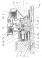
- Fig. 1 shows a device for controlling a flow of cooling oil for an automatic transmission of a motor vehicle.
- a so-called function carrier 2 is rotatably arranged with a rotation axis a.
- a first formed as a multi-plate clutch 3 cooling point and a second formed as a multi-plate clutch 4 cooling point are connected.
- the first multi-plate clutch 3 is actuated via a first annular piston 13
- the second multi-disk clutch 4 is actuated via a second annular piston 14.
- the annular piston 13, 14 are supported on the function carrier 2 plate springs 13a, 14a provided.
- the drive sides of the switching elements 3, 4 are connected via a connecting element 16 and the function carrier 2 with the transmission shaft 1.
- the function carrier 2 is therefore also a carrier of the switching elements 3, 4.
- a so-called rotary oil supply 19, also known as rotary oil transfer 19, provided, ie the cooling oil is passed from a housing-fixed channel 20 in an annular groove 21 in the gear shaft 1. From there, the cooling oil passes through a radial bore 22, an axial bore 23 and a further radial bore 24 in an oil passage 25 of the function carrier 2 and from there into the cooling oil valve 17.
- cooling oil valve 17 acting as a siphon manifold 26, designed as radial inwardly directed pocket 26, arranged in the body 2a of the function carrier 2. From the pocket 26, a dashed oil channel 26a leads to an outlet opening 26b on the outer circumference of the body 2a of the function carrier 2.
- the cooling oil is thus first performed with the cooling oil valve 17 via the pocket 26 radially inwardly and then radially outward. This emptying of the oil space of the cooling oil valve 17 is avoided. This is - as explained below - necessary or advantageous for reasons of centrifugal force compensation by buoyancy.
- the cooling oil passes under the action of centrifugal force and along the slotted plate spring 13a to the lamellar switching element 3, where a demand-based cooling takes place.
- a cooling oil valve 17 is shown.
- a second circumferentially offset cooling oil valve is provided, which is associated with the second lamellae switching element 4, so that the second switching element 4 can be cooled demand-oriented. This is incidentally also from the description Fig. 2 out.
- the cooling oil valve 17 is electrically actuated, in the illustrated embodiment by an electric motor 27, which is arranged in an annularly formed electronic module 28.
- the electronics module 28, which functions as an electronic control unit, is the subject of a separate patent application simultaneously filed by the applicant with the internal file reference ZF 003896. The subject of this simultaneous application is fully incorporated in the disclosure of the present application.
- the cooling oil valve 17 in conjunction with the electric motor 27 forms an actuator, also called an actuator, and has a rotary spindle 17a and a valve closure member 17b connected to it via a movement thread.
- the rotary spindle 17a is connected to a hollow shaft 17c on which an armature of the electric motor 27 not provided with a reference numeral is disposed.
- the rotary spindle 17a and the hollow shaft 17c are subject to a centrifugal force effect at rotating function carrier 2, which can be compensated at least partially by the buoyancy of the lubricating oil and the formation of the valve components in terms of shape and material.
- the electronic module 28, in particular the electric motor 27 receives its electrical energy and its signals for closing and opening the cooling oil valve 17 on an inductive basis: this is on the one hand a housing-side primary coil (without reference numeral) and on the other hand arranged in the electronic module 28 secondary coil 30 (see. Fig. 3 ) arranged. Further details of the electronics module 28 will be described in connection with the description of Fig. 3 explained.
- Fig. 2 shows a section of a lubricating oil circuit diagram for the two lamellar switching elements 3, 4, which are shown symbolically and the switching elements 3, 4 in Fig. 1 correspond.
- the circuit diagram for the lubricating oil corresponds to the circuit diagram for the cooling oil, since the same oil is used for both lubrication and cooling.
- the lubricating or cooling oil is conveyed through a constant pressure pump 33 preferably driven by the internal combustion engine of the motor vehicle and at an approximately constant pressure level of approximately 1.5 bar at the rotary oil transfer 19 (cf. Fig. 1 ) passed to the transmission shaft and thus to the cooling oil valve 17 and another parallel-connected cooling oil valve 31.
- the constant pressure pump 33 is designed as a variable displacement pump, wherein the actual pressure is used for control.
- the cooling oil valves 17, 31 may be designed as switching valves (simple variant) or as control valves, wherein the switching valve, preferably designed as a solenoid valve, only on and connects, ie when an acute cooling demand, eg. B. occurs due to overheating or excessive heating.
- the amount of cooling oil can also be adjusted - depending on the cooling requirement.
- a method of cooling is that the activation of the cooling, ie the opening of the cooling oil valves 17 and / or 31 is particularly desirable when a power dissipation disturbs little or is low.
- a temperature sensor (not shown in the drawing) can be arranged, which detects the oil or component temperature and reports contactlessly to the electronic control unit 28.
- the temperature sensor can be arranged directly on the switching elements 3, 4 and immediately cause an increase in the cooling oil throughput in the event of overheating.
- Fig. 3 shows the electronic module 28, also called electronic control unit 28, as a separate structural unit in a perspective view, wherein two cooling oil valves, the in Fig. 1 illustrated cooling oil valve 17 and another identical cooling oil valve 31 are shown in section.
- the electronic module 28 has an annular housing 39, which is closed by a cover 40 to the outside. Inside the housing, the stator of the electric motor 27 is arranged (same reference numerals as in FIG Fig. 1 used for the same parts). On the housing 39 connecting piece 41 are formed, via which the electronic module 28 to the body 2a of the function carrier 2 (see. Fig. 1 ) is connected. At the same time there is a sealing of the housing 39 relative to the oil space in the body 2a of the function carrier 2 by O-rings 42.
- valves 17, 31 acting as cooling oil valves
- the remaining four valves which are identical, can be used as shut-off valves in a hydraulic circuit, as in the above-mentioned simultaneous application the applicant with the internal file reference ZF 003894 described.
- the rotary spindle 17a and the hollow shaft 17c run in the oil chamber: on the one hand they are subject to a centrifugal force and, on the other hand, experience a buoyancy directed against the centrifugal force, which is determined by the weight of the displaced oil quantity.
- the armature shaft 17c is hollow.
- materials with a low specific weight are preferably used in order to keep the mass and thus the centrifugal force effect low.
- the hollow shaft 17c is mounted twice.
- the electric motor 27 for generating a rotational movement and a magnet in conjunction with a valve lifter may be used in the manner of a solenoid valve.
- the translational movement of the valve stem is then transmitted directly to the closing member.
- the transmission of electrical energy takes place on an inductive basis: for this purpose, a secondary winding 30 is arranged within the electronic module 28 in the radially inner region, which is connected to the primary winding (not shown). Fig. 1 ) is in operative connection.
Description
- Die Erfindung betrifft eine Vorrichtung zur Steuerung eines Kühl- und/ oder Schmierölstromes nach dem Oberbegriff des Patentanspruches 1 sowie die Verwendung der Vorrichtung.
- Lamellenschaltelemente werden in Kraftfahrzeuggetrieben, insbesondere Automatgetrieben als Kupplungen und Bremsen zum Schalten von Gängen verwendet. Die Betätigung der Schaltelemente, d. h. das Schließen und Öffnen erfolgt in der Regel hydraulisch, wobei ein eigener Hydraulikkreislauf mit einer Getriebeölpumpe vorgesehen ist. Beim Schließen der Lamellenschaltelemente entsteht beim Aneinanderpressen der Lamellen Wärme infolge Reibung - die Schaltelemente müssen daher gekühlt werden, um eine Überhitzung und eine eventuelle Beschädigung-der Lamellen oder Lamellenbeläge zu vermeiden. Hierzu ist es bekannt, dem Lamellenpaket der Schaltelemente Kühlöl aus einem Schmierölkreislauf durch geeignete Verteilorgane zuzuführen. Ein Problem bei der Ölkühlung der Lamellen besteht darin, dass - insbesondere bei offener Kupplung - das Kühlöl zwischen den Lamellen zu einem erhöhten Schleppmoment führt, welches den Kreislauf der Schmierölpumpe und damit auch den Getriebewirkungsgrad belastet.
- Durch die
DE 10 2005 007 685 A1 der Anmelderin wurde eine Kühlölzuführung für ein nass laufendes Schaltelement mit einem Lamellenpaket bekannt. Dabei wird das Kühlöl in Abhängigkeit von der Kolbenstellung des Kolbens des Schaltelementes mechanisch, z. B. durch ein am Kolben befestigtes Schiebeblech gesteuert. Das Schaltelement wird somit in geschlossenem Zustand laufend mit Kühlöl beaufschlagt, welches durch Fliehkraftwirkung nach außen gegen das Schaltelement geschleudert wird. In einer weiteren Variante wird dem Lamellenpaket durch Betätigung eines Ventils bedarfsorientiert ein Kühlölstrom zugeführt. Die Kühlölzufuhr an das Schaltelement erfolgt dabei von außen über einen Ölkanal, wobei das Ventil bedarfsorientiert zu- oder abgeschaltet wird. -
US 6 408 621 B1 zeigt eine Vorrichtung gemäß den Oberbegrif des Anspruchs 1. - Es ist Aufgabe der Erfindung, den Kühl- und/ oder Schmierölstrom für mindestens eine Kühl- und/ oder Schmierstelle bedarfsorientiert zu steuern, insbesondere bei Verwendung in Getrieben.
- Die Aufgabe der Erfindung wird durch die Merkmale der unabhängigen Patentansprüche 1 und 18 gelöst. Vorteilhafte Ausgestaltungen ergeben sich aus den Unteransprüchen.
- Erfindungsgemäß ist bei einer Vorrichtung zur Steuerung eines Kühl- und/ oder Schmierölstromes ein elektrisch ansteuerbares Ventil vorgesehen, welches drehfest mit der Kühl- und/ oder Schmierstelle verbunden ist, wobei die elektrische Energie zur Betätigung des Ventils berührungslos zuführbar ist. Damit wird eine bedarfsgerechte Kühlung und/ oder Schmierung erreicht. Die Kühl- und/ oder Schmierstellen können - bei Verwendung in einem Getriebe - Lamellenschaltelemente, insbesondere Kupplungen, aber auch Lager oder Zahnräder sein. Bei Lamellenkupplungen werden Schleppmomente, die sich bei nicht bedarfsgerechter Ölzufuhr ergeben, reduziert. Die berührungslose Energieübertragung erfolgt vorzugsweise auf induktiver Basis. Dadurch werden Steckverbindungen und Reibungsverluste vermieden.
- Nach einer bevorzugten Ausführungsform ist das Ventil zumindest bereichsweise in einem Funktionsträger angeordnet, welcher drehfest mit der Welle verbunden ist. Die Kühl- und/ oder Schmierstellen, vorzugsweise Lamellenkupplungen in einem Getriebe sind somit über den Funktionsträger drehfest mit der Welle, vorzugsweise einer Getriebewelle verbunden.
- Nach einer weiteren bevorzugten Ausführungsform ist das Ventil, im Folgenden auch Kühlölventil genannt, primärseitig, d. h. auf seiner Zuströmseite über erste Ölkanäle im Funktionsträger und/ oder in der Welle sowie über einen Drehölübertrager mit einer stationären Schmierölquelle verbunden; die Ölzuführung kann also auch direkt vom Drehölübertrager in die Ölkanäle des Funktionsträgers erfolgen. Da bevorzugt mehrere Kühlölventile auf dem Umfang des Funktionsträgers und mehrere Schaltelemente am Funktionsträger angeordnet sind, ist es von Vorteil, dass nur ein Drehölübertrager, d. h. nur eine durch Dichtelemente abgedichtete Übergabestelle zwischen Gehäuse und rotierender Getriebewelle vorgesehen ist. Dadurch werden Reibungs- und Leckageverluste vermieden. Der Funktionsträger, der noch weitere Funktionen aufweist, also ein Multifunktionsträger ist, fungiert in diesem Falle als Ventil- und Ölverteilgehäuse, in welchem das vom Drehölübertrager zugeführte Schmieröl auf mehrere Kühlölventile im Funktionsträger verteilt wird.
- Nach einer weiteren bevorzugten Ausführungsform sind dem Kühlölventil sekundärseitig, d. h. auf seiner Abströmseite zweite Ölkanäle zugeordnet, welche im Funktionsträger angeordnet sind und Austrittsöffnungen im Bereich des bzw. der Schaltelemente aufweisen. Aus den Austrittsöffnungen tritt das Öl bei geöffnetem Ventil aus und wird durch geeignete konstruktive Mittel, z. B. Ablenkelemente und durch Fliehkraftwirkung an das oder die Lamellenpakete oder sonstige Kühl- und/ oder Schmierstellen herangeführt oder abgeschleudert. Dadurch wird eine wirksame Kühlung erreicht.
- Nach einer weiteren bevorzugten Ausführungsform ist im Bereich der zweiten Ölkanäle ein radial nach innen gerichteter Krümmer angeordnet. Durch diesen Krümmer, der die Wirkung eines Syphon hat, wird verhindert, dass das Ventilgehäuse leerläuft und nicht mehr mit Öl befüllt ist. Das Öl wird also nach dem Austritt aus dem Ventilgehäuse entsprechend dem Syphon-Prinzip zunächst auf einen kleineren Durchmesserentgegen der Fliehkraft - geführt und erst dann zum Lamellenschaltelement geleitet. Hierdurch wird sichergestellt, dass der Raum, in dem sich bewegliche Teile des Ventils befinden, mit Öl gefüllt bleibt und dadurch eine Fliehkraftkompensation ermöglicht wird. Zur Kompensation der Fliehkraft ist es erforderlich, dass die beweglichen Ventilteile einen hinreichenden Auftrieb durch das Schmieröl erfahren.
- Nach einer weiteren bevorzugten Ausführungsform ist das Ventil als Schalt- oder Regelventil ausgebildet. Dadurch ist es einerseits möglich, das Ventil bei gleichem Kühlölstrom entweder ein- oder auszuschalten oder den Kühlölstrom hinsichtlich seiner Menge zu regeln. Bei starker Überhitzung kann somit mehr Kühlöl zugeführt werden, bei geringer Erhitzung reicht ein geringerer Kühlölstrom.
- Nach einer weiteren bevorzugten Ausführungsform ist das Ventil Teil eines Aktuators, d. h. dem Ventil oder dem Ventilschließglied ist ein Stellmotor oder Antrieb zugeordnet, welcher das Öffnen und Schließen des Ventils bewirkt. Der Aktuator umfasst einen Elektromotor, der seine Drehbewegung auf eine Ventilspindel überträgt, welche über ein Gewinde die Drehbewegung in eine Translationsbewegung des Ventilschließgliedes umsetzt. Damit können Zwischenstellungen und ein relativ hoher Dichtdruck des Ventilschließgliedes erreicht werden.
- Nach einer weiteren bevorzugten Ausführungsform ist das Ventil als Magnetventil ausgebildet. Damit entfällt eine Drehbewegung zu Gunsten einer reinen Translationsbewegung eines Ventilstößels. Durch das Magnetventil wird eine höhere Dynamik in der Ventilcharakteristik erreicht.
- Nach einer weiteren bevorzugten Ausführungsform ist am Funktionsträger ein elektronisches Steuergerät, im Folgenden auch Elektronikmodul genannt, befestigbar, welches an den Funktionsträger angepasst ist und mit diesem eine Funktionseinheit bildet. Die berührungslose Übertragung von elektrischer Energie und/oder Signalen kann über eine gehäusefest angeordnete Primärspule sowie eine im Elektronikmodul angeordnete, d. h. mitrotierende Sekundärspule erfolgen. Das Elektronikmodul bildet somit mit dem ortsfesten Teil der Energieübertragungseinrichtung eine erste Schnittstelle und mit den elektrisch ansteuerbaren Aktuatoren eine zweite Schnittstelle.
- Nach einer weiteren bevorzugten Ausführungsform ist der mindestens eine Aktuator zumindest teilweise im elektronischen Steuergerät aufnehmbar. Dabei kann es sich um Teile des elektrischen Antriebes des Aktuators wie den Stator eines Elektromotors oder die Magnetspule eines Elektromagneten handeln. Diese Teile werden von einem Gehäuse des elektronischen Steuergerätes umschlossen.
- Nach einer weiteren bevorzugten Ausführungsform sind mehrere Ventile im Funktionsträger und im Elektronikmodul über den Umfang verteilt angeordnet. Dabei können neben den oben erwähnten Kühlölventilen zur Kühlung von Schaltelementen auch Absperrventile eines Hydraulikkreislaufes zur Schaltung der Schaltelemente angeordnet werden. Der Hydraulikkreislauf, der ein höheres Druckniveau aufweist, kann über eine eigene Drehölzuführung an eine Druckölquelle angeschlossen werden. Mit einem solchen Absperrventil kann der Schließdruck bei geschlossener Kupplung im Schließzylinder ohne Betätigung der Pumpe aufrechterhalten werden. Ein derartiges Absperrventil ist Gegenstand einer zeitgleich von der Anmelderin eingereichten Patentanmeldung mit dem internen Aktenzeichen ZF 003894, die hiermit vollumfänglich in den Offenbarungsgehalt der vorliegenden Anmeldung einbezogen wird.
- Nach einer weiteren bevorzugten Ausführungsform sind bewegliche Teile des Aktuators, also beispielsweise die Ankerwelle und die Ventilspindel, welche sich in dem rotierenden Funktionsträger befinden, schwimmend in Kühl- bzw. Schmieröl angeordnet. Damit wird erreicht, dass die beweglichen Teile einen Auftrieb erfahren, welcher die Fliehkraft zumindest teilweise kompensiert. Damit können die beweglichen Teile auch bei größeren Drehzahlen zur Ausübung ihrer Funktion ohne größeren Widerstand bewegt werden.
- Nach einer weiteren bevorzugten Ausführungsform kann die mittlere Dichte der beweglichen Teile durch geeignete Maßnahmen an die Dichte des Kühlöls angenähert werden. Beispielsweise kann die Ankerwelle hohl ausgebildet werden, sodass sich ein größeres Volumen und damit eine größere Auftriebskraft ergibt. Andererseits können durch Verwendung von Werkstoffen geringer Dichte, z. B. Kunststoff oder Leichtmetall die Masse der beweglichen Teile und damit die Fliehkraft verringert werden.
- Nach einer weiteren bevorzugten Ausführungsform sind mehrere Ventile an einen Drehübertrager anschließbar. Damit werden die Reibungsverluste bei der Ölzuführung reduziert.
- Nach einer weiteren bevorzugten Ausführungsform ist ein Temperatursensor zur Erfassung der Temperatur des Kühl- und/ oder Schmierölstromes vorgesehen, beispielsweise im Bereich einer zu kühlenden Lamellenkupplung oder eines Lagers. Bei Abweichung des gemessenen Ist-Wertes kann der Sollwert über die elektronische Steuereinrichtung nachgeführt werden.
- Nach einer weiteren bevorzugten Ausführungsform wird der Kühl- und/ oder Schmierölstrom über eine Konstantpumpe gefördert, d. h. dem Drehölübertrager zugeführt. Dabei kann eine Pumpe verwendet werden, welche unabhängig vom Ölbedarf den Öldruck zumindest annähernd konstant hält. Dies kann z. B. - bei Kraftfahrzeuggetrieben - über eine von einem Verbrennungsmotor angetriebene Verstellpumpe erfolgen, bei welcher der Ist-Druck zur Regelung benutzt wird.
- Nach einer weiteren bevorzugten Ausführungsform ist die zumindest eine Kühlund/ oder Schmierstelle als Lamellenkupplung ausgebildet. Durch den bedarfgerecht gesteuerten Kühlölstrom werden z. B. Schleppmomente bei geöffneter Kupplung reduziert.
- Nach einem weiteren Aspekt der Erfindung wird die oben beschriebene Vorrichtung zur Steuerung eines Kühl- und/ oder Schmierölstromes bei einem Getriebe für ein Kraftfahrzeug, insbesondere einem Automatgetriebe, verwendet. Die oben beschriebene Vorrichtung eignet sich aufgrund ihrer kompakten Bauweise, ihrer Vielseitigkeit (Multifunktionsträger) und ihrer berührungslosen Energieübertragung besonders für den Einsatz in Automatgetrieben für Kraftfahrzeuge, weil sie den Wirkungsgrad des Getriebes verbessert.
- Ein Ausführungsbeispiel der Erfindung ist in der Zeichnung dargestellt und wird im Folgenden näher beschrieben, wobei sich aus der Beschreibung und/oder der Zeichnung weitere Merkmale und/ oder Vorteile ergeben können. Es zeigen
- Fig. 1
- einen Axialschnitt einer erfindungsgemäßen Vorrichtung mit einem Ventil für eine Kühlölzuführung zu einem Schaltelement eines Getriebes,
- Fig. 2
- ein Schaltschema für einen Kühl- und Schmierölstrom und
- Fig. 3
- ein Elektronikmodul zur Aufnahme von Aktuatoren.
-
Fig. 1 zeigt eine Vorrichtung zur Steuerung eines Kühlölstromes für ein Automatgetriebe eines Kraftfahrzeuges. Auf einer Getriebewelle 1 ist drehfest ein so genannter Funktionsträger 2 mit einer Rotationsachse a angeordnet. Mit dem Funktionsträger 2 sind eine erste als Lamellenkupplung 3 ausgebildete Kühlstelle und eine zweite als Lamellenkupplung 4 ausgebildete Kühlstelle verbunden. Die erste Lamellenkupplung 3 wird über einen ersten Ringkolben 13, und die zweite Lamellenkupplung 4 wird über einen zweiten Ringkolben 14 betätigt. Für die Rückstellung der Ringkolben 13, 14 sind am Funktionsträger 2 abgestützte Tellerfedern 13a, 14a vorgesehen. Die Antriebsseiten der Schaltelemente 3, 4 sind über ein Verbindungselement 16 und den Funktionsträger 2 mit der Getriebewelle 1 verbunden sind. Der Funktionsträger 2 ist somit auch Träger der Schaltelemente 3, 4. - Erfindungsgemäß ist in dem Funktionsträger 2, welcher zwei miteinander verbundene Körper 2a, 2b umfasst, ein Ventil 17, im Folgenden auch Kühlölventil 17 genannt, angeordnet, welches einen Kühlölstrom zu dem Lamellenschaltelement 3 kontrolliert. Zwischen einem (schematisch dargestellten) Getriebegehäuse 18 und der Getriebewelle 1 ist eine so genannte Drehölzuführung 19, auch Drehölübertrager 19 gernannt, vorgesehen, d. h. das Kühlöl wird von einem gehäusefesten Kanal 20 in eine Ringnut 21 in der Getriebewelle 1 übergeben. Von dort gelangt das Kühlöl über eine Radialbohrung 22, eine Axialbohrung 23 und eine weitere Radialbohrung 24 in einen Ölkanal 25 des Funktionsträgers 2 und von dort in das Kühlölventil 17. Auf der Abströmseite des Kühlölventils 17 ist ein als Syphon wirkender Krümmer 26, ausgebildet als radial nach innen gerichtete Tasche 26, im Körper 2a des Funktionsträgers 2 angeordnet. Von der Tasche 26 führt ein gestrichelt dargestellter Ölkanal 26a zu einer Austrittsöffnung 26b am Außenumfang des Körpers 2a des Funktionsträger 2. Das Kühlöl wird also bei geöffnetem Kühlölventil 17 zunächst über die Tasche 26 radial nach innen und anschließend radial nach außen geführt. Damit wird eine Entleerung des Ölraumes des Kühlölventils 17 vermieden. Dies ist - wie unten erläutert wird - aus Gründen der Fliehkraftkompensation durch Auftrieb erforderlich oder vorteilhaft. Aus der Austrittsöffnung 26b gelangt das Kühlöl unter der Einwirkung der Fliehkraft und entlang der geschlitzten Tellerfeder 13a zum Lamellenschaltelement 3, wo eine bedarfsgerechte Kühlung erfolgt. In der Zeichnung ist nur ein Kühlölventil 17 dargestellt. Vorzugsweise ist jedoch noch ein zweites in Umfangsrichtung versetztes Kühlölventil vorgesehen, welches dem zweiten Lamellenschaltelement 4 zugeordnet ist, damit auch das zweite Schaltelement 4 bedarfsorientiert gekühlt werden kann. Dies geht im Übrigen auch aus der Beschreibung zur
Fig. 2 hervor. - Das Kühlölventil 17 wird elektrisch betätigt, im dargestellten Ausführungsbeispiel durch einen Elektromotor 27, der in einem ringförmig ausgebildeten Elektronikmodul 28 angeordnet ist. Das Elektronikmodul 28, welches als elektronisches Steuergerät fungiert, ist Gegenstand einer separaten zeitgleich eingereichten Patentanmeldung der Anmelderin mit dem internen Aktenzeichen ZF 003896. Der Gegenstand dieser zeitgleichen Anmeldung wird vollumfänglich in den Offenbarungsgehalt der vorliegenden Anmeldung einbezogen. Das Kühlölventil 17 in Verbindung mit dem Elektromotor 27 bildet einen Aktuator, auch Aktor genannt, und weist eine Drehspindel 17a sowie ein mit ihr über ein Bewegungsgewinde verbundenes Ventilschließglied 17b auf. Die Drehspindel 17a ist mit einer Hohlwelle 17c verbunden, auf welcher ein nicht mit einer Bezugszahl versehener Anker des Elektromotors 27 angeordnet ist. Die Drehspindel 17a sowie die Hohlwelle 17c unterliegen bei rotierendem Funktionsträger 2 einer Fliehkraftwirkung, welche zumindest teilweise durch den Auftrieb des Schmieröls sowie die Ausbildung der Ventilkomponenten hinsichtlich Form und Werkstoff kompensiert werden kann. Wichtig für den Auftrieb ist, dass die beweglichen Teile des Ventils 17, d. h. die Hohlwelle 17c, die Ventilspindel 17a und das Ventilschließglied 17b von Öl umgeben, d. h. schwimmend im Kühlöl angeordnet sind. Das Elektronikmodul 28, insbesondere der Elektromotor 27 erhält seine elektrische Energie sowie seine Signale zum Schließen und Öffnen des Kühlölventils 17 auf induktiver Basis: hierzu sind einerseits eine gehäuseseitige Primärspule (ohne Bezugszahl) und andererseits eine im Elektronikmodul 28 angeordnete Sekundärspule 30 (vgl.
Fig. 3 ) angeordnet. Weitere Einzelheiten des Elektronikmoduls 28 werden im Zusammenhang mit der Beschreibung vonFig. 3 erläutert. -
Fig. 2 zeigt einen Ausschnitt aus einem Schmierölschaltplan für die beiden Lamellenschaltelemente 3, 4, welche symbolisch dargestellt sind und den Schaltelementen 3, 4 inFig. 1 entsprechen. Der Schaltplan für das Schmieröl entspricht dem Schaltplan für das Kühlöl, da sowohl für die Schmierung als auch für die Kühlung dasselbe Öl verwendet wird. Das Schmier- bzw. Kühlöl wird durch eine vorzugsweise vom Verbrennungsmotor des Kraftfahrzeuges angetriebene Konstantdruckpumpe 33 gefördert und mit einem annähernd konstanten Druckniveau von ca. 1,5 bar am Drehölübertrager 19 (vgl.Fig. 1 ) an die Getriebewelle und damit an das Kühlölventil 17 sowie ein weiteres parallel geschaltetes Kühlölventil 31 übergeben. Die Konstantdruckpumpe 33 ist als Verstellpumpe ausgebildet, wobei der Ist-Druck zur Regelung benutzt wird. Möglich wäre auch eine Elektropumpe, welche in Abhängigkeit von diversen Parametern den erforderlichen Öldruck bereitstellt. Die Kühlölmenge eines jeden Schaltelementes 3, 4 wird somit separat und unabhängig voneinander geregelt. Die Kühlölventile 17, 31 können als Schaltventile (einfache Variante) oder als Regelventile ausgeführt sein, wobei das Schaltventil, vorzugsweise als Magnetventil ausgebildet, nur auf und zuschaltet, d. h. dann, wenn ein akuter Kühlbedarf, z. B. durch Überhitzung oder starke Erwärmung auftritt. Im Falle eines Regelventils kann zusätzlich die Kühlölmenge - je nach Kühlbedarf - eingestellt werden. Ein Verfahren zur Kühlung besteht darin, dass die Einschaltung der Kühlung, d. h. das Öffnen der Kühlölventile 17 und/ oder 31 insbesondere dann angestrebt wird, wenn eine Verlustleistung wenig stört oder gering ist. Dies ist beispielsweise dann der Fall, wenn sich das Getriebe im Schubbetrieb befindet (z. B. bei Bergabfahrt oder beim Bremsen), wenn der vom Schleppmoment betroffene Getriebeteil ohnehin abgebremst werden soll (z. B. bei einer Lastschaltung) oder wenn das betroffene Schaltelement geschlossen ist oder mit geringer Differenzdrehzahl rotiert. Ferner kann ein Kühlbedarf dann bestehen, wenn die Kupplung unter starker Erwärmung geöffnet wird und ein Nachkühlbedarf besteht. Um das Schleppmoment durch einen Kühlölstrom gering zu halten, wird die Nachkühlung nach der erforderlichen Zeitspanne wieder abgeschaltet. - Optional kann im Bereich des Kühlölstromes ein (in der Zeichnung nicht dargestellter) Temperatursensor angeordnet sein, welcher die Öl- oder Bauteiltemperatur erfasst und berührungslos an das elektronische Steuergerät 28 meldet. Beispielsweise kann der Temperatursensor direkt an den Schaltelementen 3, 4 angeordnet sein und im Falle einer Überhitzung sofort eine Erhöhung des Kühlöldurchsatzes bewirken.
-
Fig. 3 zeigt das Elektronikmodul 28, auch elektronisches Steuergerät 28 genannt, als separate Baueinheit in perspektivischer Darstellung, wobei zwei Kühlölventile, das inFig. 1 dargestellte Kühlölventil 17 sowie ein weiteres identisches Kühlölventil 31 im Schnitt dargestellt sind. Das Elektronikmodul 28 weist ein ringförmig ausgebildetes Gehäuse 39 auf, welches durch einen Deckel 40 nach außen abgeschlossen ist. Innerhalb des Gehäuses ist der Stator des Elektromotors 27 angeordnet (es werden gleiche Bezugszahlen wie inFig. 1 für gleiche Teile verwendet). Am Gehäuse 39 sind Anschlussstutzen 41 angeformt, über welche das Elektronikmodul 28 mit dem Körper 2a des Funktionsträgers 2 (vgl.Fig. 1 ) verbunden wird. Gleichzeitig erfolgt eine Abdichtung des Gehäuses 39 gegenüber dem Ölraum im Körper 2a des Funktionsträgers 2 durch O-Ringe 42. In der Zeichnung sind vier Ventile, zwei mit den Bezugszahlen 17, 31 und zwei weitere ohne Bezugszahlen erkennbar. Insgesamt könnten also sechs Ventile auf dem Umfang des Elektronikmoduls 28 angeordnet werden, wobei die Ventile 17, 31 als Kühlölventile fungieren - die restlichen vier Ventile, die identisch ausgebildet sind, können als Absperrventile in einem Hydraulikschaltkreis verwendet werden, wie in der oben erwähnten zeitgleichen Anmeldung der Anmelderin mit dem internen Aktenzeichen ZF 003894 beschrieben. Wie bereits oben ausgeführt, laufen die Drehspindel 17a und die Hohlwelle 17c im Ölraum: sie unterliegen einerseits einer Fliehkraftwirkung und erfahren andererseits einen der Fliehkraft entgegen gerichteten Auftrieb, weicher durch das Gewicht der verdrängten Ölmenge bestimmt wird. Um eine Erhöhung des Auftriebs zu erreichen, ist die Ankerwelle 17c hohl ausgebildet. Zusätzlich werden bevorzugt Werkstoffe mit geringem spezifischen Gewicht verwendet, um die Masse und damit die Fliehkraftwirkung gering zu halten. Wie aus der Zeichnung ersichtlich, ist die Hohlwelle 17c zweifach gelagert. Anstelle des Elektromotors 27 zur Erzeugung einer Drehbewegung kann auch ein Magnet in Verbindung mit einem Ventilstößel, nach Art eines Magnetventils verwendet werden. Die translatorische Bewegung des Ventilstößels wird dann direkt auf das Schließglied übertragen. Wie bereits oben erwähnt, erfolgt die Übertragung von elektrischer Energie auf induktiver Basis: hierfür ist innerhalb des Elektronikmoduls 28 im radial innen liegenden Bereich eine Sekundärwicklung 30 angeordnet, welche mit der hier nicht dargestellten Primärwicklung (vgl.Fig. 1 ) in Wirkverbindung steht. - Weitere Einzelheiten über Aufbau und Wirkungsweise des Elektronikmoduls 28 sind der zeitgleich eingereichten Anmeldung der Anmelderin mit dem internen Aktenzeichen ZF 003896, wie oben erwähnt, zu entnehmen.
-
- 1
- Getriebewelle
- 2
- Funktionsträger
- 2a
- Körper
- 2b
- Körper
- 3
- erstes Schaltelement
- 4
- zweites Schaltelement
- 13
- erster Ringkolben
- 13a
- Tellerfeder
- 14
- zweiter Ringkolben
- 14a
- Tellerfeder
- 16
- Verbindungselement
- 17
- Kühlölventil
- 17a
- Drehspindel
- 17b
- Schließglied
- 17c
- Hohlwelle
- 18
- Getriebegehäuse
- 19
- Drehölzuführung
- 20
- Ölkanal
- 21
- Ringnut
- 22
- Radialbohrung
- 23
- Axialbohrung
- 24
- Radialbohrung
- 25
- Ölkanal
- 26
- Krümmer
- 26a
- Ölkanal
- 26b
- Austrittsöffnung
- 27
- Elektromotor
- 28
- Elektronisches Steuergerät
- 30
- Sekundärspule
- 31
- Kühlölventil
- 33
- Konstantdruckpumpe
- 39
- Gehäuse (Elektronikmodul)
- 40
- Deckel
- 41
- Anschlussstutzen
- 42
- O-Ring
- a
- Rotationsachse
Claims (18)
- Vorrichtung zur Steuerung mindestens eines Kühl- und/ oder Schmierölstromes mittels mindestens eines Ventils (17) für mindestens eine mit einer Welle (1) verbundene Kühl- und/ oder Schmierstelle (3, 4), dadurch gekennzeichnet, dass das Ventil (17) elektrisch ansteuerbar, drehfest mit der mindestens einen Kühl- und/ oder Schmierstelle (3, 4) verbunden und dass die elektrische Energie zur Betätigung des Ventils (17) berührungslos zuführbar ist.
- Vorrichtung nach Anspruch 1, dadurch gekennzeichnet, dass das Ventil (17) zumindest bereichsweise in einem drehfest mit der Welle (1) verbundenen Funktionsträger (2) angeordnet ist.
- Vorrichtung nach Anspruch 2, dadurch gekennzeichnet, dass der Kühl- und/ oder Schmierölstrom dem Ventil (17) über erste Ölkanäle (25, 24, 23) im Funktionsträger (2) und/ oder in der Welle (1) sowie über einen Drehölübertrager (19) zuführbar ist.
- Vorrichtung nach Anspruch 2 oder 3, dadurch gekennzeichnet, dass dem Ventil (17) abströmseitig zweite Ölkanäle (26, 26a) zugeordnet sind, welche im Funktionsträger (2) angeordnet sind und Austrittsöffnungen (26b) im Bereich der mindestens einen Kühl- und/ oder Schmierstelle (3) aufweisen.
- Vorrichtung nach Anspruch 4, dadurch gekennzeichnet, dass die zweiten Ölkanäle (26a) zwischen dem Ventil (17) und den Austrittsöffnungen (26b) einen radial nach innen gerichteten Krümmer (26) aufweisen.
- Vorrichtung nach einem der Ansprüche 1 bis 5, dadurch gekennzeichnet, dass das Ventil (17) als Schalt- oder Regelventil ausgebildet ist.
- Vorrichtung nach einem der Ansprüche 1 bis 6, dadurch gekennzeichnet, dass das mindestens eine Ventil (17) Teil eines Aktuators ist und durch einen Elektromotor (27), eine Ankerwelle (17c) sowie eine Ventilspindel (17a) betätigbar ist.
- Vorrichtung nach einem der Ansprüche 1 bis 6, dadurch gekennzeichnet, dass das mindestens eine Ventil (17) Teil eines Aktuators und als Magnetventil ausgebildet ist.
- Vorrichtung nach einem der Ansprüche 1 bis 8, dadurch gekennzeichnet, dass am Funktionsträger (2) ein elektronisches Steuergerät (28) befestigbar ist.
- Vorrichtung nach Anspruch 9, dadurch gekennzeichnet, dass der mindestens eine Aktuator zumindest teilweise im elektronischen Steuergerät (28) aufnehmbar ist.
- Vorrichtung nach einem der Ansprüche 1 bis 10, dadurch gekennzeichnet, dass mehrere Ventile (17) im Funktionsträger (2) und/ oder im elektronischen Steuergerät. (28) über den Umfang verteilt angeordnet sind.
- Vorrichtung nach einem der Ansprüche 2 bis 11, dadurch gekennzeichnet, dass bewegliche Teile (17a, 17b, 17c) des Aktuators in dem drehfest mit der mindestens einen Kühl- und/ oder Schmierstelle (3, 4) verbundenen Funktionsträgers (2) aufgenommen und im Kühlöl schwimmend angeordnet sind.
- Vorrichtung nach Anspruch 12, dadurch gekennzeichnet, dass die mittlere Dichte der beweglichen Teile (17a, 17b, 17c) des Aktuators durch geeignete Werkstoffauswahl und/ oder geometrische Gestaltung der Dichte des Kühlöls angenähert ist.
- Vorrichtung nach einem der Ansprüche 3 bis 13, dadurch gekennzeichnet, dass der über den Drehölübertrager (19) zugeführte Kühl- und/ oder Schmierölstrom mindestens einem weiteren Ventil (31) zuführbar ist.
- Vorrichtung nach einem der Ansprüche 1 bis 14, dadurch gekennzeichnet, dass im Bereich des Kühl- und/ oder Schmierölstromes ein Temperatursensor angeordnet ist.
- Vorrichtung nach einem der vorhergehenden Ansprüche, dadurch gekennzeichnet, dass der Kühl- und/ oder Schmierölstrom von einer Konstantdruckpumpe (33) förderbar ist.
- Vorrichtung nach einem der Ansprüche 1 bis 16, dadurch gekennzeichnet, dass die mindestens eine Kühl- und/ oder Schmierstelle (3, 4) als Lamellenschaltelement (3, 4) ausgebildet ist.
- Verwendung einer Vorrichtung zur Steuerung eines Kühl- und/ oder Schmierölstromes nach einem der Ansprüche 1 bis 17 in einem Getriebe für Kraftfahrzeuge.
Applications Claiming Priority (2)
| Application Number | Priority Date | Filing Date | Title |
|---|---|---|---|
| DE102011084584A DE102011084584A1 (de) | 2011-10-17 | 2011-10-17 | Vorrichtung zur Steuerung eines Kühl- und/oder Schmierölstromes |
| PCT/EP2012/067914 WO2013056905A1 (de) | 2011-10-17 | 2012-09-13 | Vorrichtung zur steuerung eines kühl- und/oder schmierölstromes |
Publications (2)
| Publication Number | Publication Date |
|---|---|
| EP2769111A1 EP2769111A1 (de) | 2014-08-27 |
| EP2769111B1 true EP2769111B1 (de) | 2016-08-17 |
Family
ID=46832411
Family Applications (1)
| Application Number | Title | Priority Date | Filing Date |
|---|---|---|---|
| EP12758484.5A Not-in-force EP2769111B1 (de) | 2011-10-17 | 2012-09-13 | Vorrichtung zur steuerung eines kühl- und/oder schmierölstromes |
Country Status (6)
| Country | Link |
|---|---|
| US (1) | US9470329B2 (de) |
| EP (1) | EP2769111B1 (de) |
| JP (1) | JP6185475B2 (de) |
| CN (1) | CN103890434B (de) |
| DE (1) | DE102011084584A1 (de) |
| WO (1) | WO2013056905A1 (de) |
Families Citing this family (10)
| Publication number | Priority date | Publication date | Assignee | Title |
|---|---|---|---|---|
| DE102011084585A1 (de) * | 2011-10-17 | 2013-04-18 | Zf Friedrichshafen Ag | Elektronische Steuereinrichtung zur Steuerung von Aktuatoren |
| DE102012102850A1 (de) | 2012-04-02 | 2013-10-02 | B. Braun Melsungen Ag | Fluidfördervorrichtung und Fluidförderverfahren für medizinische Anwendungen |
| JP5695013B2 (ja) * | 2012-11-02 | 2015-04-01 | 本田技研工業株式会社 | 回転電機の磁石温度推定装置及び磁石温度推定方法 |
| EP3080473B1 (de) * | 2013-12-09 | 2019-08-21 | Schaeffler Technologies AG & Co. KG | Hydraulikanordnung für doppelkupplung sowie verfahren zum ansteuern oder kühlen der doppelkupplung |
| DE102014209056A1 (de) * | 2014-05-14 | 2015-11-19 | Zf Friedrichshafen Ag | Hybridantriebsanordnung eines Kraftfahrzeuges |
| CN107542569B (zh) | 2016-06-27 | 2021-05-28 | 舍弗勒技术股份两合公司 | 热管理模块 |
| JP6601382B2 (ja) * | 2016-12-24 | 2019-11-06 | トヨタ自動車株式会社 | 車両用動力伝達装置 |
| JP6509930B2 (ja) | 2017-03-10 | 2019-05-08 | 本田技研工業株式会社 | 油圧クラッチ装置 |
| SE541048C2 (en) * | 2017-07-07 | 2019-03-19 | Scania Cv Ab | An oil distributor for a lubricating and cooling system in a powertrain |
| DE102019205571A1 (de) * | 2019-04-17 | 2020-10-22 | Zf Friedrichshafen Ag | Kühlölleitelement sowie Antriebsstrang und Hybridmodul mit diesem |
Family Cites Families (22)
| Publication number | Priority date | Publication date | Assignee | Title |
|---|---|---|---|---|
| JPS61112123U (de) * | 1984-12-25 | 1986-07-16 | ||
| JPH0221337U (de) * | 1988-07-27 | 1990-02-13 | ||
| JPH08121501A (ja) * | 1994-10-24 | 1996-05-14 | Tochigi Fuji Ind Co Ltd | 変速機 |
| US5613588A (en) * | 1995-02-02 | 1997-03-25 | Clark Equipment Company | Clutch coolant flow control device |
| JPH09112643A (ja) * | 1995-10-17 | 1997-05-02 | Nippon Seiko Kk | トロイダル型無段変速機 |
| US6408621B1 (en) * | 2000-09-11 | 2002-06-25 | Engineered Dynamics Corporation | Fluid coupling assembly |
| DE10150704A1 (de) * | 2001-10-13 | 2003-04-17 | Bayerische Motoren Werke Ag | Lamellenkupplung, insbesondere für Motorräder |
| JP2003172439A (ja) * | 2001-12-10 | 2003-06-20 | Toyota Motor Corp | 潤滑装置 |
| ATE541127T1 (de) * | 2003-11-14 | 2012-01-15 | Eagle Ind Co Ltd | Mengeregelventil |
| US7112156B2 (en) | 2004-02-25 | 2006-09-26 | General Motors Corporation | Transmission with miniature motor for control to oil flow |
| DE102005007685A1 (de) | 2005-02-19 | 2006-08-31 | Zf Friedrichshafen Ag | Kühlölzuführung für ein nasslaufendes Schalt-bzw. Anfahrelement |
| KR101277057B1 (ko) * | 2005-07-29 | 2013-06-20 | 호르톤 인코포레이티드 | 전자기적으로 구동되는 비스코스 클러치 |
| JP4687540B2 (ja) * | 2006-04-12 | 2011-05-25 | 株式会社デンソー | 流体制御弁 |
| DE102006049275B4 (de) * | 2006-10-19 | 2022-11-17 | Zf Friedrichshafen Ag | Getriebevorrichtung mit mindestens einem über eine wenigstens eine elektrische Komponente aufweisende Aktuatorik betätigbaren Schaltelement |
| IN2009KN02406A (de) | 2006-12-22 | 2015-08-07 | Borgwarner Inc | |
| ITMI20071071A1 (it) * | 2007-05-25 | 2008-11-26 | Piaggio & C Spa | Dispositivo automatico di comando di un gruppo frizione integrato con un asservimento idraulico per realizzare lo slittamento controllato dei dischi della frizione |
| DE102008000644A1 (de) * | 2008-03-13 | 2009-09-17 | Zf Friedrichshafen Ag | Drehübertragungsanordnung |
| CN102216585B (zh) * | 2008-11-23 | 2014-10-15 | 博格华纳公司 | 带有传感器反馈的风扇传动系统 |
| WO2010059491A2 (en) * | 2008-11-23 | 2010-05-27 | Borgwarner Inc. | Fan drive system with oil pressure control |
| DE102009002261A1 (de) * | 2009-04-07 | 2010-10-14 | Zf Friedrichshafen Ag | Getriebevorrichtung mit wenigstens einem über eine Aktorik betätigbaren Schaltelement |
| JP5875777B2 (ja) * | 2011-03-31 | 2016-03-02 | 株式会社不二工機 | 電動弁 |
| DE102011084583A1 (de) * | 2011-10-17 | 2013-04-18 | Zf Friedrichshafen Ag | Betätigungseinrichtung zum Betätigen von Schaltelementen |
-
2011
- 2011-10-17 DE DE102011084584A patent/DE102011084584A1/de not_active Withdrawn
-
2012
- 2012-09-13 JP JP2014534985A patent/JP6185475B2/ja not_active Expired - Fee Related
- 2012-09-13 WO PCT/EP2012/067914 patent/WO2013056905A1/de active Application Filing
- 2012-09-13 CN CN201280050073.0A patent/CN103890434B/zh not_active Expired - Fee Related
- 2012-09-13 EP EP12758484.5A patent/EP2769111B1/de not_active Not-in-force
- 2012-09-13 US US14/352,100 patent/US9470329B2/en active Active
Also Published As
| Publication number | Publication date |
|---|---|
| CN103890434A (zh) | 2014-06-25 |
| US9470329B2 (en) | 2016-10-18 |
| JP2014528561A (ja) | 2014-10-27 |
| CN103890434B (zh) | 2017-04-26 |
| DE102011084584A1 (de) | 2013-04-18 |
| US20140264112A1 (en) | 2014-09-18 |
| JP6185475B2 (ja) | 2017-08-23 |
| EP2769111A1 (de) | 2014-08-27 |
| WO2013056905A1 (de) | 2013-04-25 |
Similar Documents
| Publication | Publication Date | Title |
|---|---|---|
| EP2769111B1 (de) | Vorrichtung zur steuerung eines kühl- und/oder schmierölstromes | |
| EP3354920B1 (de) | Kupplungsanordnung für einen antriebsstrang und getriebeanordnung mit einer solchen kupplungsanordnung | |
| EP1989461B1 (de) | Elektromagnetische schalteinrichtung mit linearmotor | |
| EP2769110B1 (de) | Betätigungseinrichtung zum betätigen von schaltelementen | |
| DE102012024699A1 (de) | Kupplungsanordnung mit einer Doppelkupplungseinrichtung | |
| EP1482195B1 (de) | Kupplungsvorrichtung und Verfahren zum Betreiben einer Lamellenkupplung | |
| DE102005027610A1 (de) | Drehmomentübertragungseinrichtung und Antriebsstrang mit dieser | |
| EP1857698B1 (de) | Kopplungsanordnung | |
| EP1566526A2 (de) | Regelbarer Antrieb für ein Kraftfahrzeug | |
| DE102014114590B4 (de) | Hydrauliksteuervorrichtung für Hydraulikdrehmomentwandler | |
| DE102010039171A1 (de) | Kupplung mit schaltbarer Kühlung sowie Verfahren zur Steuerung dieser Kupplung | |
| EP3921562B1 (de) | System zum betätigen einer parksperre | |
| EP2417373B1 (de) | Getriebevorrichtung mit wenigstens einem über eine aktorik betätigbaren schaltelement | |
| WO2005119077A1 (de) | Nasslaufende lamellenkupplung | |
| WO2013041409A1 (de) | Kupplungseinheit | |
| EP3239549A1 (de) | Reibkupplung mit zwischenelement | |
| DE102009006422B4 (de) | Doppelkupplungsanordnung für Kraftfahrzeuge und Betätigungsverfahren hierfür | |
| DE202013002494U1 (de) | Automatgetriebe mit verrastbaren Schaltelementen | |
| EP1398520A2 (de) | Lamellenkupplung | |
| EP0728966A2 (de) | Schalt-/Regelventil zum Steuern von hydrodynamischen Drehmomentwandlern automatischer Schaltgetriebe | |
| EP1398519B1 (de) | Lamellenkupplung | |
| DE10337556A1 (de) | Lamellenkupplung | |
| DE102022130689B3 (de) | Vorrichtung und Verfahren zur Steuerung einer Kupplungseinrichtung | |
| DE102010063084B3 (de) | Antriebsstrang eines Hydraulikantriebs mit einer Kupplung | |
| DE102017217722B4 (de) | Kühlmittelsystem zum Kühlen eines Schaltelements |
Legal Events
| Date | Code | Title | Description |
|---|---|---|---|
| PUAI | Public reference made under article 153(3) epc to a published international application that has entered the european phase |
Free format text: ORIGINAL CODE: 0009012 |
|
| 17P | Request for examination filed |
Effective date: 20140313 |
|
| AK | Designated contracting states |
Kind code of ref document: A1 Designated state(s): AL AT BE BG CH CY CZ DE DK EE ES FI FR GB GR HR HU IE IS IT LI LT LU LV MC MK MT NL NO PL PT RO RS SE SI SK SM TR |
|
| DAX | Request for extension of the european patent (deleted) | ||
| REG | Reference to a national code |
Ref country code: DE Ref legal event code: R079 Ref document number: 502012007991 Country of ref document: DE Free format text: PREVIOUS MAIN CLASS: F16D0025120000 Ipc: F16K0031020000 |
|
| GRAP | Despatch of communication of intention to grant a patent |
Free format text: ORIGINAL CODE: EPIDOSNIGR1 |
|
| RIC1 | Information provided on ipc code assigned before grant |
Ipc: F16D 25/12 20060101ALI20160303BHEP Ipc: F16D 13/72 20060101ALN20160303BHEP Ipc: F16D 25/10 20060101ALN20160303BHEP Ipc: F16K 31/02 20060101AFI20160303BHEP Ipc: F16D 25/0638 20060101ALN20160303BHEP |
|
| RIC1 | Information provided on ipc code assigned before grant |
Ipc: F16D 25/12 20060101ALI20160309BHEP Ipc: F16K 31/02 20060101AFI20160309BHEP Ipc: F16D 25/10 20060101ALN20160309BHEP Ipc: F16D 25/0638 20060101ALN20160309BHEP Ipc: F16D 13/72 20060101ALN20160309BHEP |
|
| INTG | Intention to grant announced |
Effective date: 20160324 |
|
| GRAS | Grant fee paid |
Free format text: ORIGINAL CODE: EPIDOSNIGR3 |
|
| GRAA | (expected) grant |
Free format text: ORIGINAL CODE: 0009210 |
|
| AK | Designated contracting states |
Kind code of ref document: B1 Designated state(s): AL AT BE BG CH CY CZ DE DK EE ES FI FR GB GR HR HU IE IS IT LI LT LU LV MC MK MT NL NO PL PT RO RS SE SI SK SM TR |
|
| REG | Reference to a national code |
Ref country code: GB Ref legal event code: FG4D Free format text: NOT ENGLISH |
|
| REG | Reference to a national code |
Ref country code: CH Ref legal event code: EP |
|
| REG | Reference to a national code |
Ref country code: IE Ref legal event code: FG4D Free format text: LANGUAGE OF EP DOCUMENT: GERMAN |
|
| REG | Reference to a national code |
Ref country code: AT Ref legal event code: REF Ref document number: 821439 Country of ref document: AT Kind code of ref document: T Effective date: 20160915 |
|
| REG | Reference to a national code |
Ref country code: DE Ref legal event code: R096 Ref document number: 502012007991 Country of ref document: DE |
|
| REG | Reference to a national code |
Ref country code: NL Ref legal event code: MP Effective date: 20160817 |
|
| REG | Reference to a national code |
Ref country code: LT Ref legal event code: MG4D |
|
| PG25 | Lapsed in a contracting state [announced via postgrant information from national office to epo] |
Ref country code: HR Free format text: LAPSE BECAUSE OF FAILURE TO SUBMIT A TRANSLATION OF THE DESCRIPTION OR TO PAY THE FEE WITHIN THE PRESCRIBED TIME-LIMIT Effective date: 20160817 Ref country code: FI Free format text: LAPSE BECAUSE OF FAILURE TO SUBMIT A TRANSLATION OF THE DESCRIPTION OR TO PAY THE FEE WITHIN THE PRESCRIBED TIME-LIMIT Effective date: 20160817 Ref country code: RS Free format text: LAPSE BECAUSE OF FAILURE TO SUBMIT A TRANSLATION OF THE DESCRIPTION OR TO PAY THE FEE WITHIN THE PRESCRIBED TIME-LIMIT Effective date: 20160817 Ref country code: IT Free format text: LAPSE BECAUSE OF FAILURE TO SUBMIT A TRANSLATION OF THE DESCRIPTION OR TO PAY THE FEE WITHIN THE PRESCRIBED TIME-LIMIT Effective date: 20160817 Ref country code: NO Free format text: LAPSE BECAUSE OF FAILURE TO SUBMIT A TRANSLATION OF THE DESCRIPTION OR TO PAY THE FEE WITHIN THE PRESCRIBED TIME-LIMIT Effective date: 20161117 Ref country code: NL Free format text: LAPSE BECAUSE OF FAILURE TO SUBMIT A TRANSLATION OF THE DESCRIPTION OR TO PAY THE FEE WITHIN THE PRESCRIBED TIME-LIMIT Effective date: 20160817 Ref country code: LT Free format text: LAPSE BECAUSE OF FAILURE TO SUBMIT A TRANSLATION OF THE DESCRIPTION OR TO PAY THE FEE WITHIN THE PRESCRIBED TIME-LIMIT Effective date: 20160817 |
|
| PG25 | Lapsed in a contracting state [announced via postgrant information from national office to epo] |
Ref country code: GR Free format text: LAPSE BECAUSE OF FAILURE TO SUBMIT A TRANSLATION OF THE DESCRIPTION OR TO PAY THE FEE WITHIN THE PRESCRIBED TIME-LIMIT Effective date: 20161118 Ref country code: SE Free format text: LAPSE BECAUSE OF FAILURE TO SUBMIT A TRANSLATION OF THE DESCRIPTION OR TO PAY THE FEE WITHIN THE PRESCRIBED TIME-LIMIT Effective date: 20160817 Ref country code: PL Free format text: LAPSE BECAUSE OF FAILURE TO SUBMIT A TRANSLATION OF THE DESCRIPTION OR TO PAY THE FEE WITHIN THE PRESCRIBED TIME-LIMIT Effective date: 20160817 Ref country code: PT Free format text: LAPSE BECAUSE OF FAILURE TO SUBMIT A TRANSLATION OF THE DESCRIPTION OR TO PAY THE FEE WITHIN THE PRESCRIBED TIME-LIMIT Effective date: 20161219 Ref country code: ES Free format text: LAPSE BECAUSE OF FAILURE TO SUBMIT A TRANSLATION OF THE DESCRIPTION OR TO PAY THE FEE WITHIN THE PRESCRIBED TIME-LIMIT Effective date: 20160817 Ref country code: LV Free format text: LAPSE BECAUSE OF FAILURE TO SUBMIT A TRANSLATION OF THE DESCRIPTION OR TO PAY THE FEE WITHIN THE PRESCRIBED TIME-LIMIT Effective date: 20160817 Ref country code: BE Free format text: LAPSE BECAUSE OF NON-PAYMENT OF DUE FEES Effective date: 20160930 |
|
| PG25 | Lapsed in a contracting state [announced via postgrant information from national office to epo] |
Ref country code: RO Free format text: LAPSE BECAUSE OF FAILURE TO SUBMIT A TRANSLATION OF THE DESCRIPTION OR TO PAY THE FEE WITHIN THE PRESCRIBED TIME-LIMIT Effective date: 20160817 Ref country code: EE Free format text: LAPSE BECAUSE OF FAILURE TO SUBMIT A TRANSLATION OF THE DESCRIPTION OR TO PAY THE FEE WITHIN THE PRESCRIBED TIME-LIMIT Effective date: 20160817 |
|
| REG | Reference to a national code |
Ref country code: CH Ref legal event code: PL |
|
| REG | Reference to a national code |
Ref country code: DE Ref legal event code: R097 Ref document number: 502012007991 Country of ref document: DE |
|
| PG25 | Lapsed in a contracting state [announced via postgrant information from national office to epo] |
Ref country code: BG Free format text: LAPSE BECAUSE OF FAILURE TO SUBMIT A TRANSLATION OF THE DESCRIPTION OR TO PAY THE FEE WITHIN THE PRESCRIBED TIME-LIMIT Effective date: 20161117 Ref country code: SK Free format text: LAPSE BECAUSE OF FAILURE TO SUBMIT A TRANSLATION OF THE DESCRIPTION OR TO PAY THE FEE WITHIN THE PRESCRIBED TIME-LIMIT Effective date: 20160817 Ref country code: CZ Free format text: LAPSE BECAUSE OF FAILURE TO SUBMIT A TRANSLATION OF THE DESCRIPTION OR TO PAY THE FEE WITHIN THE PRESCRIBED TIME-LIMIT Effective date: 20160817 Ref country code: SM Free format text: LAPSE BECAUSE OF FAILURE TO SUBMIT A TRANSLATION OF THE DESCRIPTION OR TO PAY THE FEE WITHIN THE PRESCRIBED TIME-LIMIT Effective date: 20160817 Ref country code: DK Free format text: LAPSE BECAUSE OF FAILURE TO SUBMIT A TRANSLATION OF THE DESCRIPTION OR TO PAY THE FEE WITHIN THE PRESCRIBED TIME-LIMIT Effective date: 20160817 |
|
| PLBE | No opposition filed within time limit |
Free format text: ORIGINAL CODE: 0009261 |
|
| STAA | Information on the status of an ep patent application or granted ep patent |
Free format text: STATUS: NO OPPOSITION FILED WITHIN TIME LIMIT |
|
| REG | Reference to a national code |
Ref country code: IE Ref legal event code: MM4A |
|
| PG25 | Lapsed in a contracting state [announced via postgrant information from national office to epo] |
Ref country code: MC Free format text: LAPSE BECAUSE OF FAILURE TO SUBMIT A TRANSLATION OF THE DESCRIPTION OR TO PAY THE FEE WITHIN THE PRESCRIBED TIME-LIMIT Effective date: 20160817 |
|
| REG | Reference to a national code |
Ref country code: FR Ref legal event code: ST Effective date: 20170531 |
|
| 26N | No opposition filed |
Effective date: 20170518 |
|
| GBPC | Gb: european patent ceased through non-payment of renewal fee |
Effective date: 20161117 |
|
| PG25 | Lapsed in a contracting state [announced via postgrant information from national office to epo] |
Ref country code: CH Free format text: LAPSE BECAUSE OF NON-PAYMENT OF DUE FEES Effective date: 20160930 Ref country code: LI Free format text: LAPSE BECAUSE OF NON-PAYMENT OF DUE FEES Effective date: 20160930 Ref country code: FR Free format text: LAPSE BECAUSE OF NON-PAYMENT OF DUE FEES Effective date: 20161017 Ref country code: IE Free format text: LAPSE BECAUSE OF NON-PAYMENT OF DUE FEES Effective date: 20160913 |
|
| PG25 | Lapsed in a contracting state [announced via postgrant information from national office to epo] |
Ref country code: LU Free format text: LAPSE BECAUSE OF NON-PAYMENT OF DUE FEES Effective date: 20160913 Ref country code: SI Free format text: LAPSE BECAUSE OF FAILURE TO SUBMIT A TRANSLATION OF THE DESCRIPTION OR TO PAY THE FEE WITHIN THE PRESCRIBED TIME-LIMIT Effective date: 20160817 |
|
| REG | Reference to a national code |
Ref country code: BE Ref legal event code: MM Effective date: 20160930 |
|
| PG25 | Lapsed in a contracting state [announced via postgrant information from national office to epo] |
Ref country code: GB Free format text: LAPSE BECAUSE OF NON-PAYMENT OF DUE FEES Effective date: 20161117 |
|
| PG25 | Lapsed in a contracting state [announced via postgrant information from national office to epo] |
Ref country code: HU Free format text: LAPSE BECAUSE OF FAILURE TO SUBMIT A TRANSLATION OF THE DESCRIPTION OR TO PAY THE FEE WITHIN THE PRESCRIBED TIME-LIMIT; INVALID AB INITIO Effective date: 20120913 |
|
| PG25 | Lapsed in a contracting state [announced via postgrant information from national office to epo] |
Ref country code: MK Free format text: LAPSE BECAUSE OF FAILURE TO SUBMIT A TRANSLATION OF THE DESCRIPTION OR TO PAY THE FEE WITHIN THE PRESCRIBED TIME-LIMIT Effective date: 20160817 Ref country code: CY Free format text: LAPSE BECAUSE OF FAILURE TO SUBMIT A TRANSLATION OF THE DESCRIPTION OR TO PAY THE FEE WITHIN THE PRESCRIBED TIME-LIMIT Effective date: 20160817 Ref country code: MT Free format text: LAPSE BECAUSE OF FAILURE TO SUBMIT A TRANSLATION OF THE DESCRIPTION OR TO PAY THE FEE WITHIN THE PRESCRIBED TIME-LIMIT Effective date: 20160817 Ref country code: IS Free format text: LAPSE BECAUSE OF FAILURE TO SUBMIT A TRANSLATION OF THE DESCRIPTION OR TO PAY THE FEE WITHIN THE PRESCRIBED TIME-LIMIT Effective date: 20160817 |
|
| PG25 | Lapsed in a contracting state [announced via postgrant information from national office to epo] |
Ref country code: TR Free format text: LAPSE BECAUSE OF FAILURE TO SUBMIT A TRANSLATION OF THE DESCRIPTION OR TO PAY THE FEE WITHIN THE PRESCRIBED TIME-LIMIT Effective date: 20160817 Ref country code: AL Free format text: LAPSE BECAUSE OF FAILURE TO SUBMIT A TRANSLATION OF THE DESCRIPTION OR TO PAY THE FEE WITHIN THE PRESCRIBED TIME-LIMIT Effective date: 20160817 |
|
| REG | Reference to a national code |
Ref country code: AT Ref legal event code: MM01 Ref document number: 821439 Country of ref document: AT Kind code of ref document: T Effective date: 20170913 |
|
| PG25 | Lapsed in a contracting state [announced via postgrant information from national office to epo] |
Ref country code: AT Free format text: LAPSE BECAUSE OF NON-PAYMENT OF DUE FEES Effective date: 20170913 |
|
| PGFP | Annual fee paid to national office [announced via postgrant information from national office to epo] |
Ref country code: DE Payment date: 20200901 Year of fee payment: 9 |
|
| REG | Reference to a national code |
Ref country code: DE Ref legal event code: R119 Ref document number: 502012007991 Country of ref document: DE |
|
| PG25 | Lapsed in a contracting state [announced via postgrant information from national office to epo] |
Ref country code: DE Free format text: LAPSE BECAUSE OF NON-PAYMENT OF DUE FEES Effective date: 20220401 |