EP2768082A1 - Elektrische Kontaktierungseinheit mit einem Flachkabel mit gerillter und planer Oberfläche - Google Patents
Elektrische Kontaktierungseinheit mit einem Flachkabel mit gerillter und planer Oberfläche Download PDFInfo
- Publication number
- EP2768082A1 EP2768082A1 EP20140000465 EP14000465A EP2768082A1 EP 2768082 A1 EP2768082 A1 EP 2768082A1 EP 20140000465 EP20140000465 EP 20140000465 EP 14000465 A EP14000465 A EP 14000465A EP 2768082 A1 EP2768082 A1 EP 2768082A1
- Authority
- EP
- European Patent Office
- Prior art keywords
- ribbon cable
- jacket
- contacting
- wires
- contacting system
- Prior art date
- Legal status (The legal status is an assumption and is not a legal conclusion. Google has not performed a legal analysis and makes no representation as to the accuracy of the status listed.)
- Granted
Links
Images

Classifications
-
- H—ELECTRICITY
- H01—ELECTRIC ELEMENTS
- H01R—ELECTRICALLY-CONDUCTIVE CONNECTIONS; STRUCTURAL ASSOCIATIONS OF A PLURALITY OF MUTUALLY-INSULATED ELECTRICAL CONNECTING ELEMENTS; COUPLING DEVICES; CURRENT COLLECTORS
- H01R12/00—Structural associations of a plurality of mutually-insulated electrical connecting elements, specially adapted for printed circuits, e.g. printed circuit boards [PCB], flat or ribbon cables, or like generally planar structures, e.g. terminal strips, terminal blocks; Coupling devices specially adapted for printed circuits, flat or ribbon cables, or like generally planar structures; Terminals specially adapted for contact with, or insertion into, printed circuits, flat or ribbon cables, or like generally planar structures
- H01R12/50—Fixed connections
- H01R12/59—Fixed connections for flexible printed circuits, flat or ribbon cables or like structures
- H01R12/65—Fixed connections for flexible printed circuits, flat or ribbon cables or like structures characterised by the terminal
- H01R12/67—Fixed connections for flexible printed circuits, flat or ribbon cables or like structures characterised by the terminal insulation penetrating terminals
-
- H—ELECTRICITY
- H01—ELECTRIC ELEMENTS
- H01R—ELECTRICALLY-CONDUCTIVE CONNECTIONS; STRUCTURAL ASSOCIATIONS OF A PLURALITY OF MUTUALLY-INSULATED ELECTRICAL CONNECTING ELEMENTS; COUPLING DEVICES; CURRENT COLLECTORS
- H01R13/00—Details of coupling devices of the kinds covered by groups H01R12/70 or H01R24/00 - H01R33/00
- H01R13/46—Bases; Cases
- H01R13/52—Dustproof, splashproof, drip-proof, waterproof, or flameproof cases
- H01R13/5205—Sealing means between cable and housing, e.g. grommet
-
- H—ELECTRICITY
- H01—ELECTRIC ELEMENTS
- H01B—CABLES; CONDUCTORS; INSULATORS; SELECTION OF MATERIALS FOR THEIR CONDUCTIVE, INSULATING OR DIELECTRIC PROPERTIES
- H01B7/00—Insulated conductors or cables characterised by their form
- H01B7/08—Flat or ribbon cables
- H01B7/0823—Parallel wires, incorporated in a flat insulating profile
Definitions
- the present invention relates to an electrical contacting system according to the preamble of claim 1.
- a contacting system is for example from DE DE-A-10 2006 039 604 known.
- a ribbon cable grooved on both sides is contacted by means of piercing contacts according to the penetration method.
- the piercing contacts are attached to the lid of a multi-part housing. The housing is aligned with special markings on the grooved cable and then closed.
- the object of the invention is to increase the operating temperature range of such a contacting system and at the same time to improve the tightness of the contacting system.
- the invention is based on the consideration that for a particularly dense and resistant to bypass influences stable and reliable fürdringungsAuthtechnik the design of the sheath of the ribbon cable is essential. If the wires are contacted in one tap sleeve from one side, then these contacting side of the ribbon cable and the opposite or opposite side fulfill different functions and should accordingly satisfy other requirements. On the contacting side, on which the contacting means or screws are pushed through the insulating jacket and thus pierce the jacket, a high accuracy and tightness is desirable. The vein should be contacted as centrally as possible. The resulting contact point should be good against
- a ribbon cable satisfying the above requirements can be realized by making the side to which the wires are to be contacted planar and by causing the other side of the ribbon cable to have grooves or constrictions, e.g. essentially places lesser thickness of the sheath, having. Due to the planar design and thus over the contacting flat shell shape, the contact means are each introduced perpendicular to the mantle surface, so that deformations or stresses of the material are kept low and a hit accuracy is achieved. At the same time, the contacting points on a flat surface are easier to seal than on a corrugated surface.
- the thinning of the cladding in the area between the wires on the other side reduces the influence of material softening of the cladding and insulation, especially at higher temperatures. If the cable is inserted into a tapping sleeve, the shape of which in the receiving area corresponds to the corrugated structure of the ribbon cable through molded receiving troughs, the desired centering or guiding of the cores is also carried out so that displacements relative to the contact means are kept small.
- a rectangular, circumferential sealing strip is provided on the underside of the Abgriffmanschetten top.
- This sealing strip extends to a parallel to the outer edges of the inserted ribbon cable and spans the ribbon cable at two longitudinally spaced surfaces. In this way, a rectangular, enclosed by the sealing strip contacting region on Abgriffmanschetten top educated.
- the circumferential sealing strip is pressed so that a sufficient seal of the contacting region with respect to the outside world and thus against external influences, in particular environmental influences is realized.
- the jacket underside of the ribbon cable has a wave-like contour, in which the wave troughs are formed by grooves.
- the contour of the underside of the casing between the grooves is preferably circular segment-like, with an imaginary circle center in, seen in cross-section, the center of the respective vein.
- the circular segments particularly preferably span an angular range of less than 180 °, so that a sufficient jacket thickness is still realized between the wires.
- the jacket outer sides of the ribbon cable are advantageously designed asymmetrically in their shape, so that a direction-dependent connection is made possible. This is advantageous, for example, when the wires are designed for different currents or types of transmission and generally serves to unambiguously assign the wires to the individual contacting points.
- the wires of the ribbon cable are preferably individually isolated electrically. In an alternative embodiment, groups of adjacent wires or even all wires can be embedded in a common insulation.
- the ribbon cable preferably has 2 to 10, in particular 5 wires.
- the tapping sleeve has a number of cores corresponding number of contacting means for a fürdringungstitle ist. These are preferably designed as screws.
- the tapping sleeve is constructed in two parts with an upper part and a lower part, wherein the upper part has a receiving area that conforms to the upper side of the jacket, and the lower part has a receiving area that conforms to the lower side of the jacket.
- the upper part and the lower part are designed in their shape such that the ribbon cable is received in a form-fitting manner only in a defined position of them.
- a mechanical coding can be achieved and ensured that the contacting of the wires in the desired orientation of the ribbon cable takes place.
- a closure device for, in particular detachable, attachment of upper part and lower part to each other is provided.
- the ribbon cable can first be placed in the tapping sleeve and precisely positioned before the cuff is closed and the contacting means guided through the jacket and insulation.
- the advantages of the invention are, in particular, that due to the flat jacket upper side, high sealing properties are achieved after the contacting has taken place.
- the corrugated design of the underside of the jacket, the lines or wires are supported against the contact pressure of justify michsschrauben, whereby they are held laterally in position, so that a reliable contact is achieved.
- the ribbon cable combines in this way the advantageous properties of the two profile designs plan and riffled. Due to the corrugation of the mantle underside and reduced in this way Jacket thickness reduces the influence of material softening of the insulation and the jacket at higher temperatures. It is achieved with simultaneous realization of a high density accurate placement of the conductors to the Kunststofftechniksschrauben in a fürdringungskombericht mich.
- An in Fig. 1 illustrated ribbon cable 2 has a sheath 6 and a shell in which are arranged or embedded substantially in a common plane five electrical wires 12, wherein the wires 12 are each surrounded separately from an electrical insulation 18.
- the jacket 6 has a jacket top side 24 and a jacket bottom side 30, which are aligned substantially parallel to one another and parallel to the plane in which the wires 12 are arranged.
- the ribbon cable 2 further has two outer shells 36, 42, which lie respectively at the edge regions of the ribbon cable 2 between the upper side of the jacket 24 and the lower side 30 of the jacket.
- the ribbon cable 2 is suitable for a fürdringungsAuthtechnik when in a Contacting direction 48 perpendicular to a longitudinal direction 54 of the wires 12 contact elements for contacting the wires 12 are each guided by jacket 6 and insulation 18.
- the jacket 6 consists of materials such as ethylene vinyl acetate, polyvinyl chloride, crosslinked polyethylene, Polyolefincompound and halogen-free plastic.
- a circumferential sealing strip 140 shown in the presentation of the Fig. 1 .
- the sealing strip 140 extends along the outer shells 36, 42 and overlaps the ribbon cable 2 in two places. In the presentation of the Fig. 1 These are the respective end sides of the illustrated cable portion of the ribbon cable 2. In this way, the circumferential sealing strip 140 encloses a rectangular contacting region of the ribbon cable. 2
- the ribbon cable 2 is designed such that it has a high degree of impermeability to the environment after contacting and at the same time insensitive to environmental influences.
- the mantle top 24 is designed plan, that is, it is flat designed and accordingly does not follow the shape of the round wires 14 and their insulation 18th
- the jacket underside 30 is essentially wave-shaped with grooves 60 between two wires 12. That is, the contour of the jacket underside 30 follows in regions (in the manner of a circle segment) the contour of the cores 12, which are round in cross-section, or the insulation surrounding them 18. In order that the jacket thickness does not decrease too much in the region of 60, the circle segments each cover an angular range of less than 180 °.
- the corrugation on the underside of the jacket 30 reduces the sheath thickness of the ribbon cable in each case in the region between two cores 12.
- the grooved sheath underside 30 reduces the influence of material softening of insulation 18 and sheath 6 at higher temperatures.
- the ribbon cable 2 also has a mechanical coding. This is designed such that the outer contours of the two outer shells 36, 42 are executed different. While the outer shell side 42 is semicircular and merges into the upper side of the jacket 24 and the lower side 30 of the jacket as it were, the jacket outer side 36 has a corner or right-angled edge 66 at its transition to the upper side 24 of the jacket. The transition of the outer shell 36 side to the lower side of the shell 30 is configured as in the outer shell side 42. Between this transition and the Known 66, the outer shell side 36 is straight or flat.
- a defined orientation of the ribbon cable with respect to this device can be defined in relation to a device into which the flat cable is inserted, in particular a device for contacting the wires 12. This is advantageous, for example, when the different wires 12 of the ribbon cable are designed differently for different transmission purposes or with regard to their material properties or load capacity, so that it can be ensured that the correct wires 12 are selected during the contacting.
- An in Fig. 2 in a section illustrated contacting system 80 comprises the ribbon cable 2 according to Fig. 1 and a Abgriffmanschette 86, which is constructed in two parts of an upper part 92 and a lower part 98.
- the Abgriffmanschette consists in the embodiment of polyamide.
- the upper part 92 has a closure device 104 with a hinge joint.
- the closure device 104 comprises on one side of the upper part 92 a cross-sectionally circular segment-like bracket 108 which receives a rib-like projection 110 of the lower part 98 in the assembled state of the Abgriffmanschette 86 to form the hinge joint.
- the VerInstitutvorrichutng further comprises on the opposite side of the Abgriffmanschette 86 for forming the hinge joint, a fastening means 116, which is designed in the embodiment as a fastening screw, with which upper part 92 and lower part 98 are releasably connected to each other.
- the upper part 92 of the tapping sleeve 86 has a number of cores corresponding to the plurality of sleeves 122, in which serving as a contacting means Druckmaschinesschrauben 128 are screwed.
- a pointed screw end 134 in the sense of a fürdringungsAuthtechnik first the jacket 6 of the ribbon cable 2 and then the insulation 18 of the core 12 until the end of the screw 134 touches the core 12 or penetrates into this.
- the individual contact screws 128 are each associated with lines 146, which are contacted with that wire 12 or brought into electrically conductive connection, into which the respective screw end 134 has been led.
- a deformation force F K is illustrated, which exerts the respective contacting screw 128 when screwing in on the jacket 6 of the ribbon cable 2. Due to the plan or planar design of the mantle top 24, this force is distributed evenly over the casing 6 when screwing in the respective contacting screw 128, and a high accuracy of the conductors 12 can be achieved. In a corrugated embodiment of the jacket upper side 24, which could then look similar to the jacket underside 30, such a high density could not be achieved. In the presentation of the Fig. 2 Finally, a transverse to the longitudinal direction 54 extending part of the sealing strip 140 is still recognizable.
- the sealing strip 140 extends - as already stated - along the outer shells 36, 42 in the longitudinal direction 54 and traverses the ribbon cable 2 at two points. In this way, the sealing strip 140 encloses a rectangular contacting region.
- the sealing strip 140 is pressed against the upper side of the jacket 6 of the flat ribbon cable 2 with such high pressure that all contacts are effectively sealed.
- each core 12 is as it were assigned a separate receiving trough 112.
- the central longitudinal axes of the cores 12 and the receiving cavities 112 preferably extend congruently to the effective centering of the cores 12 in the Abgriffsmanschette 86 and to increase the accuracy of Victorianssschrauben 128 when contacting the wires 12th
- Arrows 156 show the supporting forces F S of the tapping sleeve acting on the basis of the contacting in the region of each wire 12. Due to the congruent shape to the respective region of the circular segment-like contour of the jacket bottom 30 in the region of the respective core 12 designed shaping and thus enabled positive connection between the shell bottom 30 and lower part 98, the supporting forces F S act radially inward, so that the core 12 during contacting and is held in position after that and does not shift. In this way a permanent and reliable contact is guaranteed.
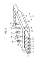
- the contacting system Fig. 2 is in Fig. 3 shown in perspective.
- Evident in this illustration is the expansion of the tapping sleeve 86 in the longitudinal direction 54 and the spatial displacement of the sleeves 122 or contacting screws 128 relative to one another in this direction.
- the distances or distances between the individual contacts are increased in comparison to a configuration in which the contacting screws would all be arranged in a direction perpendicular to the longitudinal direction 54. This also reduces the risk of a short circuit between two adjacent wires 12.
Landscapes
- Cable Accessories (AREA)
- Coupling Device And Connection With Printed Circuit (AREA)
- Details Of Connecting Devices For Male And Female Coupling (AREA)
- Insulated Conductors (AREA)
Abstract
Description
- Die vorliegende Erfindung betrifft ein elektrisches Kontaktierungssystem gemäß dem Oberbegriff des Anspruchs 1. Ein derartiges Kontaktierungssystem ist beispielsweise aus de
DE-A-10 2006 039 604 bekannt. Bei diesem bekannten Kontaktierungssystem wird ein beidseitig gerilltes Flachbandkabel mithilfe von Piercingkontakten nach der Durchdringungsmethode kontaktiert. Die Piercingkontakte sind hierzu am Deckel eines mehrteiligen Gehäuses befestigt. Das Gehäuse wird an speziellen Markierungen am gerillten Kabel ausgerichtet und sodann verschlossen. - Ausgehend hiervon liegt der Erfindung die Aufgabe zugrunde, den Betriebstemperaturbereich eines derartigen Kontaktierungssystem zu erhöhen und zugleich die Dichtigkeit des Kontaktierungssystems zu verbessern.
- Diese Aufgabe ist durch die Merkmalskombination des Anspruchs 1 in erfinderischer Weise gelöst. Die rückbezogenen Ansprüche betreffen teilweise vorteilhafte und teilweise für sich selbst erfinderische Weiterbildungen dieser Erfindung.
- Die Erfindung geht von der Überlegung aus, dass für eine besonders dichte und gegenüber Umgehungseinflüssen beständige und zuverlässige Durchdringungskontaktierung die Ausgestaltung der Ummantelung des Flachbandkabels wesentlich ist. Werden dabei die Adern in einer Abgriffmanschette von einer Seite her kontaktiert, so erfüllen diese Kontaktierungsseite des Flachbandkabels und die gegenüberliegende bzw. entgegengesetzte Seite unterschiedliche Funktionen und sollten dementsprechend auch anderen Anforderungen genügen. Auf der Kontaktierungsseite, auf der die Kontaktierungsmittel bzw. -schrauben durch den isolierenden Mantel geschoben werden und somit den Mantel durchstoßen, ist eine hohe Treffgenauigkeit und Dichtigkeit wünschenswert. Die Ader soll möglichst zentral kontaktiert werden. Die dadurch entstehende Kontaktstelle soll gut gegen
- Umwelteinflüsse geschützt werden. Auf der anderen Seite des Flachbandkabels hingegen, die gewissermaßen den Kontaktierungsmitteln gegenüber liegt, ist wünschenswert, dass sich Umgebungs- und Materialeinflüsse möglichst wenig auf die Kontaktierung auswirken. Zugleich sollte möglichst versucht werden, eine gegenseitige Verschiebung der Adern des Flachbandkabels zu den Kontaktmitteln zu vermeiden. Herkömmliche Flachbandkabel, die entweder beidseitig plan oder geriffelt ausgeführt sind, entsprechen diesen Anforderungen nur in ungenügender Weise.
- Wie nunmehr erkannt wurde, lässt sich ein Flachbandkabel, welches den oben genannten Anforderungen genügt, realisieren, indem die Seite, an welcher die Adern kontaktiert werden sollen, plan ausgeführt wird und indem die andere Seite des Flachbandkabels Rillen bzw. Einschnürungen, d.h. im Wesentlichen Stellen geringerer Dicke der Ummantelung, aufweist. Durch die plane Ausgestaltung und die damit über die Kontaktierungsseite ebene Mantelform werden die Kontaktmittel jeweils senkrecht zur Manteloberfläche eingeführt, so dass Verformungen oder Spannungen des Materials gering gehalten werden und eine Treffgenauigkeit erreicht wird. Zugleich sind die Kontaktierungsstellen auf einer planen Oberfläche leichter als auf einer geriffelten Oberfläche abzudichten. Durch die Verdünnung der Ummantelung im Bereich zwischen den Adern auf der anderen Seite wird der Einfluss der Materialerweichung der Ummantelung und der Isolierung verringert, insbesondere bei höheren Temperaturen. Wird das Kabel in eine Abgriffmanschette eingelegt, deren Formgebung im Aufnahmebereich durch eingeformte Aufnahmemulden der geriffelten Struktur des Flachbandkabels entspricht, erfolgt auch die gewünschte Zentrierung bzw. Führung der Adern, so dass Verschiebungen gegenüber den Kontaktmitteln gering gehalten werden.
- Zur Abdichtung der Kontaktierungsstellen der Adern ist an der Unterseite des Abgriffmanschetten-Oberteils eine rechteckförmige, umlaufende Dichtungsleiste vorgesehen. Diese Dichtungsleiste verläuft zum einen parallel zu den Außenkanten des eingelegten Flachbandkabels und überspannt das Flachbandkabel an zwei in Längsrichtung beabstandeten Flächen. Auf diese Weise wird ein rechteckförmiger, von der Dichtungsleiste umschlossener Kontaktierungsbereich am Abgriffmanschetten-Oberteil gebildet. Beim Schließen der Abgriffmanschette durch das Verschrauben der Befestigungsschrauben der Verschlussvorrichtung wird die umlaufende Dichtungsleiste so angepresst, dass eine ausreichende Abdichtung des Kontaktierungsbereichs gegenüber der Außenwelt und damit gegenüber externen Einflüssen, insbesondere Umwelteinflüssen realisiert ist.
- Vorteilhafterweise weist die Mantelunterseite des Flachbandkabels eine wellenartige Kontur, bei der die Wellentäler durch Rillen gebildet werden. Dabei verläuft die Kontur der Mantelunterseite zwischen den Rillen vorzugsweise kreissegmentartig, mit einem gedachten Kreismittelpunkt im, im Querschnitt gesehen, Mittelpunkt der jeweiligen Ader. Besonders bevorzugt überspannen dabei die Kreissegmente einen Winkelbereich von weniger als 180°, so dass zwischen den Adern noch eine ausreichende Manteldicke realisiert wird. Eine derartige Ausgestaltung erlaubt bei einer Einbettung des Flachbandkabels in eine Abgriffmanschette mit einem zur Mantelunterseite formkongruenten Aufnahmebereich eine Abstützung des Flachbandkabels mit im Bereich der Ader radial nach innen gerichteten Stützkräften. Dadurch wir in besonderem Maße erreicht, dass während des Kontaktierungsvorgangs die Ader nicht seitlich in Bezug auf das jeweilige Kontaktmittel verrutscht.
- Zur Realisierung einer mechanischen Kodierung sind die Mantelaußenseiten des Flachbandkabels in ihrer Formgebung vorteilhafterweise asymmetrisch ausgestaltet, so dass ein richtungsabhängiger Anschluss ermöglicht wird. Dies ist beispielsweise dann vorteilhaft, wenn die Adern für unterschiedliche Ströme oder Übertragungsarten ausgelegt sind und dient im Allgemeinen der eindeutigen Zuordnung der Adern zu den einzelnen Kontaktierungsstellen.
- Die Adern des Flachbandkabels sind vorzugsweise einzeln elektrisch isoliert. In alternativer Ausgestaltung können auch Gruppen von benachbarten Adern oder auch alle Adern in einer gemeinsamen Isolierung eingebettet sein.
- Das Flachbandkabel weist vorzugsweise 2 bis 10, insbesondere 5 Adern auf.
- Vorteilhafterweise weist die Abgriffmanschette eine der Anzahl der Adern entsprechende Anzahl von Kontaktierungsmitteln für eine Durchdringungskontaktierung auf. Diese sind bevorzugt als Schrauben ausgestaltet.
- In einer bevorzugten Ausführungsform ist die Abgriffmanschette zweiteilig aufgebaut mit einem Oberteil und einem Unterteil, wobei das Oberteil einen zur Manteloberseite formkongruenten Aufnahmebereich und das Unterteil einen zur Mantelunterseite formkongruenten Aufnahmebereich aufweist. Durch diese Ausgestaltung wird zum einen eine besonders gute Abdichtung zwischen Abgriffmanschette und Flachbandkabel erreicht. Zum anderen kann auf diese Weise eine besonders stabile und positionsgenaue Kontaktierung erreicht werden.
- Bevorzugt sind das Oberteil und das Unterteil in ihrer Formgebung derart ausgeführt, dass das Flachbandkabel nur in einer definierten Lage von ihnen formschlüssig aufgenommen wird. Dadurch kann eine mechanische Kodierung erreicht und sichergestellt werden, dass die Kontaktierung der Adern in der gewünschten Ausrichtung des Flachbandkabels erfolgt.
- Vorteilhafterweise ist eine Verschlussvorrichtung zur, insbesondere lösbaren, Befestigung von Oberteil und Unterteil aneinander vorgesehen. Das Flachbandkabel kann auf diese Weise zunächst in die Abgriffmanschette gelegt und präzise positioniert werden, bevor die Manschette geschlossen wird und die Kontaktierungsmittel durch Mantel und Isolierung geführt werden.
- Die Vorteile der Erfindung liegen insbesondere darin, dass aufgrund der planen Manteloberseite hohe Dichteigenschaften nach der erfolgten Kontaktierung erreicht werden. Durch die geriffelte Ausbildung der Mantelunterseite werden die Leitungen bzw. Adern gegen den Anpressdruck der Kontaktierungsschrauben gestützt, wodurch sie seitlich in Position gehalten werden, so dass eine zuverlässige Kontaktierung erreicht wird. Das Flachbandkabel vereint auf diese Weise die vorteilhaften Eigenschaften der beiden Profilausbildungen plan und geriffelt. Aufgrund der Riffelung der Mantelunterseite und der auf diese Weise reduzierten Mantelstärke wird der Einfluss der Materialerweichung der Isolierung und der Ummantelung bei höheren Temperaturen verringert. Es wird bei gleichzeitiger Realisierung einer hohen Dichtigkeit eine genaue Platzierung der Leiter zu den Kontaktierungsschrauben in einer Durchdringungskontaktierung erreicht.
- Aufgrund der positionsgenauen und stabilen Kontaktierung werden an den Kontaktierungsstellen hohe Ströme ermöglicht. Durch eine mechanische Kodierung des Flachbandkabels wird ein richtungsabhängiger Anschluss ermöglicht.
- Ein Ausführungsbeispiel der Erfindung wird anhand einer Zeichnung näher erläutert. Darin zeigen in stark schematisierter Darstellung:
- Fig. 1
- ein Flachbandkabel in perspektivischer Sicht mit einem vorderseitigen Schnitt in einer bevorzugten Ausführungsform,
- Fig. 2
- ein Kontaktierungssystem mit dem Flachbandkabel gemäß
Fig. 1 und einer Anschlussmanschette in einer bevorzugten Ausführungsform in einem Querschnitt und - Fig. 3
- das Kontaktierungssystem gemäß
Fig. 2 in perspektivischer Sicht. - Gleiche Teile sind in allen Figuren mit denselben Bezugszeichen versehen.
- Ein in
Fig. 1 dargestelltes Flachbandkabel 2 weist einen Mantel 6 bzw. eine Ummantelung auf, in der im Wesentlichen in einer gemeinsamen Ebene fünf elektrische Adern 12 angeordnet bzw. eingebettet sind, wobei die Adern 12 jeweils separat von einer elektrischen Isolierung 18 umgeben sind. Der Mantel 6 weist eine Manteloberseite 24 und eine Mantelunterseite 30 auf, die im Wesentlichen parallel zueinander und parallel zu der Ebene ausgerichtet sind, in der die Adern 12 angeordnet sind. Das Flachbandkabel 2 weist weiterhin zwei Mantelaußenseiten 36, 42 auf, welche jeweils an den Randbereichen des Flachbandkabels 2 zwischen Manteloberseite 24 und Mantelunterseite 30 liegen. Das Flachbandkabel 2 ist beispielsweise für eine Durchdringungskontaktierung geeignet bei der in einer Kontaktierungsrichtung 48 senkrecht zu einer Längsrichtung 54 der Adern 12 Kontaktelemente zur Kontaktierung der Adern 12 jeweils durch Mantel 6 und Isolierung 18 geführt werden. Der Mantel 6 besteht dabei aus Materialien wie Ethylenvinylacetat, Polyvinylchlorid, vernetztes Polyetylen, Polyolefincompound sowie halogenfreiem Kunststoff. - In der Darstellung der
Fig. 1 ist auch eine umlaufende Dichtungsleiste 140 dargestellt. Die Dichtungsleiste 140 verläuft entlang den Mantelaußenseiten 36, 42 und übergreift das Flachbandkabel 2 an zwei Stellen. In der Darstellung derFig. 1 sind dies die jeweiligen Endseiten des dargestellten Kabelabschnitts des Flachbandkabels 2. Auf diese Weise umschließt die umlaufende Dichtungsleiste 140 einen rechteckförmigen Kontaktierungsbereich des Flachbandkabels 2. - Das Flachbandkabel 2 ist derart ausgeführt, dass es eine hohe Dichtigkeit gegenüber der Umgebung nach erfolgter Kontaktierung aufweist und gleichzeitig unempfindlich gegenüber Umgebungseinflüssen. Dazu ist die Manteloberseite 24 plan ausgeführt, d.h., sie ist eben bzw. planer ausgestaltet und folgt dementsprechend nicht der Formgebung der rund ausgeführten Adern 12 und ihrer Isolierung 18.
- Die Mantelunterseite 30 hingegen ist im Wesentlichen wellenförmig ausgeführt mit Rillen 60 jeweils zwischen zwei Adern 12. Das heißt, die Kontur der Mantelunterseite 30 folgt bereichsweise (in der Art eines Kreissegments) der Kontur der im Querschnitt runden Adern 12 bzw. der sie jeweils umgebenden Isolierung 18. Damit im Bereich der 60 die Mantelstärke nicht zu stark abnimmt überstreichen die Kreissegmente jeweils einen Winkelbereich von weniger als 180°. Die Riffelung auf der Mantelunterseite 30 reduziert die Mantelstärke des Flachbandkabels jeweils im Bereich zwischen zwei Adern 12. Durch die gerillte Mantelunterseite 30 wird der Einfluss der Materialerweichung von Isolierung 18 und Mantel 6 bei höheren Temperaturen verringert.
- Das Flachbandkabel 2 weist darüber hinaus eine mechanische Kodierung auf. Diese ist derart ausgeführt, dass die Außenkonturen der beiden Mantelaußenseiten 36, 42 unterschiedliche ausgeführt sind. Während die Mantelaußenseite 42 halbkreisförmig ausgebildet ist und gewissermaßen fließend in Manteloberseite 24 und Mantelunterseite 30 übergeht, weist die Mantelaußenseite 36 an ihrem Übergang zur Manteloberseite 24 eine Ecke bzw. rechtwinklige Kante 66 auf. Der Übergang der Mantelaußenseite 36 zur Mantelunterseite 30 ist ausgestaltet wie bei der Mantelaußenseite 42. Zwischen diesem Übergang und der Kannte 66 verläuft die Mantelaußenseite 36 gerade bzw. plan. Durch diese unterschiedliche Formgebung der Mantelaußenseiten 36, 42 kann in Bezug auf eine Vorrichtung, in die das Flachbandkabel eingelegt wird, insbesondere eine Vorrichtung zur Kontaktierung der Adern 12, eine definierte Orientierung des Flachbandkabels in Bezug auf diese Vorrichtung definiert werden. Dies ist beispielsweise dann vorteilhaft, wenn die verschiedenen Adern 12 des Flachbandkabels für unterschiedliche Übertragungszwecke oder hinsichtlich ihrer Materialeigenschaften oder Belastbarkeit verschieden ausgelegt sind, so dass sichergestellt werden kann, dass bei der Kontaktierung die richtigen Adern 12 gewählt werden.
- Ein in
Fig. 2 in einem Schnitt dargestelltes Kontaktierungssystem 80 umfasst das Flachbandkabel 2 gemäßFig. 1 und eine Abgriffmanschette 86, welche zweiteilig aufgebaut ist aus einem Oberteil 92 und einem Unterteil 98. Die Abgriffmanschette besteht im Ausführungsbeispiel aus Polyamid. Das Oberteil 92 weist eine Verschlussvorrichtung 104 mit einem Scharniergelenk auf. Die Verschlussvorrichtung 104 umfasst auf einer Seite des Oberteils 92 eine im Querschnitt kreissegmentartig ausgebildete Klammer 108, die im zusammengesetzten Zustand der Abgriffmanschette 86 einen rippenartigen Vorsprung 110 des Unterteils 98 zur Bildung des Scharniergelenks aufnimmt. Die Verschlussvorrichutng umfasst weiterhin auf der entgegengesetzten Seite der Abgriffmanschette 86 zur Bildung des Scharniergelenks ein Befestigungsmittel 116, welches im Ausführungsbeispiel als Befestigungsschraube ausgeführt ist, mit welcher Oberteil 92 und Unterteil 98 lösbar miteinander verbunden sind. - Das Oberteil 92 der Abgriffmanschette 86 weist eine der Zahl der Adern entsprechende Mehrzahl von Hülsen 122 auf, in die als Kontaktierungsmittel dienende Kontaktierungsschrauben 128 einschraubbar sind. Beim Einschrauben der jeweiligen Kontaktierungsschraube 128 in die entsprechende Hülse 122 wird durch ein spitz ausgeführtes Schraubenende 134 im Sinne einer Durchdringungskontaktierung zunächst der Mantel 6 des Flachbandkabels 2 und dann die Isolierung 18 der Ader 12 durchbrochen, bis das Schraubenende 134 die Ader 12 berührt bzw. in diese eindringt. Den einzelnen Kontaktierungsschrauben 128 sind jeweils Leitungen 146 zugeordnet, die mit derjenigen Ader 12 kontaktiert bzw. in elektrisch leitende Verbindung gebracht werden, in die das jeweilige Schraubenende 134 hineingeführt wurde.
- Durch einen Pfeil 150 ist eine Verformungskraft FK verdeutlicht, welche die jeweilige Kontaktierungsschraube 128 beim Hereindrehen auf den Mantel 6 des Flachbandkabels 2 ausübt. Aufgrund der planen bzw. ebenen Ausgestaltung der Manteloberseite 24 wird diese Kraft beim Hineindrehen der jeweiligen Kontaktierungsschraube 128 gleichmäßig über den Mantel 6 verteilt und es lässt sich eine hohe Treffsicherheit der Adern 12 erreichen. Bei einer geriffelten Ausgestaltung der Manteloberseite 24, die dann ähnlich wie die Mantelunterseite 30 aussehen könnte, könnte eine derart hohe Dichtigkeit nicht erreicht werden. In der Darstellung der
Fig. 2 ist schließlich noch ein quer zur Längsrichtung 54 verlaufender Teil der Dichtungsleiste 140 erkennbar. Die Dichtungsleiste 140 verläuft - wie bereits ausgeführt - entlang den Mantelaußenseiten 36, 42 in Längsrichtung 54 und quert an zwei Stellen das Flachbandkabel 2. Auf diese Weise wird von der Dichtungsleiste 140 ein rechteckförmiger Kontaktierungsbereich eingeschlossen. Beim Schließen der als Befestigungsschrauben ausgestaltenen Befestigungsmittel 16 der Verschlussvorrichtung 104 wird die Dichtungsleiste 140 mit so hohem Druck an die Oberseite des Mantel 6 des Flachbandkabels 2 angedrückt, dass sämtliche Kontaktierungen wirksam abgedichtet sind. - In der Darstellung der
Fig. 2 ist weiterhin erkennbar, dass die einzelnen Kreissegmente der kreissegementartigen Kontur der Mantelunterseite 30 jeweils in Aufnahmemulden 112 im Unterteil 98 der Abgriffmanschette 86 einliegen. Jeder Ader 12 ist gleichsam eine separate Aufnahmemulde 112 zugeordnet. Die Mittellängsachsen der Adern 12 und der Aufnahmemulden 112 verlaufen vorzugsweise deckungsgleich zur wirksamen Zentrierung der Adern 12 in der Abgriffsmanschette 86 und zur Erhöhung der Treffsicherheit der Kontaktierungsschrauben 128 beim Kontaktieren der Adern 12. - Durch Pfeile 156 werden die aufgrund der Kontaktierung im Bereich jeder Ader 12 wirkenden Stützkräfte FS der Abgriffmanschette dargestellt. Aufgrund der formkongruent zum jeweiligen Bereich der kreissegmentartigen Kontur der Mantelunterseite 30 im Bereich der jeweiligen Ader 12 ausgestalteten Formgebung und der damit ermöglichten formschlüssigen Verbindung zwischen Mantelunterseite 30 und Unterteil 98 wirken die Stützkräfte FS radial nach innen, so dass die Ader 12 während des Kontaktierens und auch danach in ihrer Position gehalten wird und sich nicht verschiebt. Auf diese Weise wird eine dauerhafte und zuverlässige Kontaktierung gewährleistet.
- Das Kontaktierungssystem aus
Fig. 2 ist inFig. 3 perspektivisch dargestellt. Zu erkennen ist in dieser Darstellung die Ausdehnung der Abgriffmanschette 86 in der Längsrichtung 54 sowie die in dieser Richtung räumliche Versetzung der Hülsen 122 bzw. Kontaktierungsschrauben 128 zueinander. Durch diese räumliche Konfiguration werden die Distanzen bzw. Abstände zwischen den einzelnen Kontaktierungen erhöht im Vergleich zu einer Konfiguration, in der die Kontaktierungsschrauben alle in einer Richtung senkrecht zur Längsrichtung 54 angeordnet wären. Dadurch wird auch das Risiko eines Kurzschlusses zwischen zwei benachbarten Adern 12 reduziert. -
- 2
- Flachbandkabel
- 6
- Mantel
- 12
- Ader
- 18
- Isolierung
- 24
- Manteloberseite
- 30
- Mantelunterseite
- 36
- Mantelaußenseite
- 42
- Mantelaußenseite
- 48
- Kontaktierungsrichtung
- 54
- Längsrichtung
- 60
- Rille
- 66
- Kante
- 80
- Kontaktierungssystem
- 86
- Abgriffmanschette
- 92
- Oberteil
- 98
- Unterteil
- 104
- Verschlussvorrichtung
- 108
- Klammer
- 110
- Vorsprung
- 112
- Aufnahmemulde
- 116
- Befestigungsmittel
- 122
- Hülse
- 128
- Kontaktierungsschraube
- 134
- Schraubenende
- 140
- Dichtungsleiste
- 146
- Leitung
- 150
- Pfeil
- 156
- Pfeil
- FK
- Verformungskraft
- FS
- Stützkraft
Claims (10)
- Elektrisches Kontaktierungssystem (80) mit einem Flachbandkabel (2) mit einem Mantel (6), welcher eine plane Manteloberseite (24), eine Aderebene mit elektrischen Adern (12) und eine Mantelunterseite (30) mit zu den Adern (12) parallelen Einschnürungen zwischen jeweils zwei Adern (12) aufweist und mit einer Abgriffmanschette (86) zur elektrischen Kontaktierung der Adern (12), wobei eine umlaufende, einen rechteckförmigen Kontaktierungsbereich einschließende Dichtungsleiste (140) an der Unterseite des der Manteloberseite (24) des Flachbandkabels (2) zugewandten Oberteils (92) der Abgriffmanschette (86) angeordnet ist.
- Kontaktierungssystem (80) nach Anspruch 1
dadurch gekennzeichnet,
dass die Dichtungsleiste (140) parallel zu den Mantelaußenseiten (36, 42) des Flachbandkabels (2) verläuft und dessen Manteloberseite (24) an zwei beabstandeten Stellen quert. - Kontaktierungssystem (80) nach Anspruch 1 oder 2
dadurch gekennzeichnet,
dass die Mantelunterseite (24) des Flachbandkabels (2) eine wellenartige Kontur aufweist mit durch Rillen (60) gebildeten Wellentälern. - Kontaktierungssystem (80) nach einem der Ansprüche 1 bis 3
gekennzeichnet durch
in ihrer Formgebung asymmetrisch ausgestaltete Mantelaußenseiten (36, 42) des Flachbandkabels (2) als mechanische Codierung. - Elektrisches Kontaktierungssystem (80) nach einem der Ansprüche 1 bis 4
dadurch gekennzeichnet,
dass die Adern (12) des Flachbandkabels (2) einzeln elektrisch isoliert sind. - Kontaktierungssystem (80) nach Anspruch 5,
dadurch gekennzeichnet,
dass die Abgriffmanschette (86) eine der Anzahl der Adern (12) entsprechende Anzahl von Kontaktierungsmitteln (128) für eine Durchdringungskontaktierung aufweist. - Kontaktierungssystem (80) nach Anspruch 5 oder 6,
dadurch gekennzeichnet,
dass Abgriffmanschette (86) zweiteilig aufgebaut ist mit einem Oberteil (92) und einem Unterteil (98), wobei das Oberteil (92) einen zur Manteloberseite (24) formkongruenten Aufnahmebereich und das Unterteil (98) einen zur Mantelunterseite (30) formkongruenten Aufnahmebereich aufweist. - Kontaktierungssystem (80) nach einem der Ansprüche 5 bis 7,
dadurch gekennzeichnet,
dass das Oberteil (92) und das Unterteil (98) in ihrer Formgebung derart ausgeführt sind, dass das Flachbandkabel (2) in nur einer definierten Lage von ihnen formschlüssig aufgenommen wird. - Kontaktierungssystem (80) nach einem der Ansprüche 5 bis 8,
dadurch gekennzeichnet,
dass die Mittellängsachse jeder Ader (12) parallel, vorzugsweise deckungsgleich zur Mittellängsachse der jeweils zugeordneten Aufnahmemulde (112) verläuft. - Kontaktierungssystem (80) nach einem der Ansprüche 5 bis 9,
gekennzeichnet durch
eine Verschlussvorrichtung (104) zur lösbaren Befestigung von Oberteil (92) und Unterteil (98) aneinander.
Applications Claiming Priority (1)
| Application Number | Priority Date | Filing Date | Title |
|---|---|---|---|
| DE102013002740.3A DE102013002740A1 (de) | 2013-02-19 | 2013-02-19 | Flachkabel mit gerillter und planter Oberfläche |
Publications (2)
| Publication Number | Publication Date |
|---|---|
| EP2768082A1 true EP2768082A1 (de) | 2014-08-20 |
| EP2768082B1 EP2768082B1 (de) | 2016-06-15 |
Family
ID=50072842
Family Applications (1)
| Application Number | Title | Priority Date | Filing Date |
|---|---|---|---|
| EP14000465.6A Active EP2768082B1 (de) | 2013-02-19 | 2014-02-10 | Elektrische Kontaktierungseinheit mit einem Flachkabel mit gerillter und planer Oberfläche |
Country Status (4)
| Country | Link |
|---|---|
| US (1) | US9450314B2 (de) |
| EP (1) | EP2768082B1 (de) |
| DE (1) | DE102013002740A1 (de) |
| DK (1) | DK2768082T3 (de) |
Cited By (3)
| Publication number | Priority date | Publication date | Assignee | Title |
|---|---|---|---|---|
| EP3319179A1 (de) | 2016-11-03 | 2018-05-09 | HPH Hardegger AG | Verfahren zum elektrischen anschliessen von elektrischen geräten in einer küche |
| CN109216948A (zh) * | 2018-08-29 | 2019-01-15 | 宁波颐栎庭园用品有限公司 | 安全特低电压防水接线器 |
| WO2021046731A1 (zh) * | 2019-09-11 | 2021-03-18 | 宁波颐栎庭园用品有限公司 | 防水快速接线器 |
Families Citing this family (10)
| Publication number | Priority date | Publication date | Assignee | Title |
|---|---|---|---|---|
| CN104916354B (zh) * | 2015-04-23 | 2017-07-07 | 潍坊科技学院 | 数据线用柔软线缆 |
| WO2017151779A1 (en) * | 2016-03-02 | 2017-09-08 | Heartware, Inc. | Skin button with flat cable |
| US9954296B2 (en) * | 2016-07-07 | 2018-04-24 | Rockwell Automation Technologies, Inc. | Connector with sliding tap |
| JP6952462B2 (ja) * | 2016-12-15 | 2021-10-20 | スリーエム イノベイティブ プロパティズ カンパニー | 電線収容体、コネクタアセンブリ、及び防水性コネクタ |
| US10186789B1 (en) | 2018-04-13 | 2019-01-22 | Rustcraft Industries LLC | Keyed cable and connector system |
| US20220013938A1 (en) * | 2018-11-07 | 2022-01-13 | Iee International Electronics & Engineering S.A. | Flexible multilayer encapsulation of electrical connections |
| JP7265458B2 (ja) * | 2019-09-26 | 2023-04-26 | 日本航空電子工業株式会社 | コネクタおよび接続方法 |
| US12413009B2 (en) * | 2021-02-15 | 2025-09-09 | Raytheon Company | Cable assembly with integral seal element |
| DE102021127570A1 (de) | 2021-10-22 | 2023-04-27 | Kromberg & Schubert GmbH Cable & Wire | Kabel mit haptisch ertastbarem Verdrehindikator und Verfahren zur torsionsfreien Verlegung eines solchen Kabels |
| US12014847B2 (en) * | 2021-12-03 | 2024-06-18 | Aptiv Technologies AG | Cable for connecting system components |
Citations (5)
| Publication number | Priority date | Publication date | Assignee | Title |
|---|---|---|---|---|
| DE9101065U1 (de) * | 1991-01-31 | 1991-04-18 | Quante AG, 5600 Wuppertal | Elektrischer Verbinder für die Telekommunikation mit einer flexiblen elektrischen Schnur |
| DE19741603A1 (de) * | 1997-09-20 | 1999-03-25 | Volkswagen Ag | Elektrische Kontakteinrichtung sowie Verfahren zur Schneidkontaktherstellung |
| WO2001022534A1 (de) * | 1999-09-20 | 2001-03-29 | Woertz Ag | Kontaktierungsvorrichtung für ein flachbandkabel |
| DE102006039604A1 (de) | 2006-08-24 | 2008-02-28 | Weidmüller Interface GmbH & Co. KG | Kabel, Anschlußeinrichtung mit Kabel und Verfahren zur Herstellung des Kabels |
| WO2010040159A1 (de) * | 2008-10-06 | 2010-04-15 | Tridonicatco Connection Technology Gmbh & Co Kg | Leuchtmittel mit led |
Family Cites Families (14)
| Publication number | Priority date | Publication date | Assignee | Title |
|---|---|---|---|---|
| DE7330510U (de) | 1973-11-15 | Schorn W | Elektrische Stegleitung | |
| NL137793B (de) * | 1967-06-05 | 1900-01-01 | ||
| DE1942784B1 (de) * | 1969-08-22 | 1971-02-04 | Ibm Deutschland | Verfahren zum Ummanteln von Bandkabeln |
| US3720778A (en) * | 1972-03-28 | 1973-03-13 | Woertz O Inh H & Woertz O | Electric ribbon cable and connector assembly |
| US4209219A (en) * | 1978-11-22 | 1980-06-24 | Amp Incorporated | Method and apparatus for terminating multi-conductor cable |
| US5190468A (en) * | 1991-06-10 | 1993-03-02 | Smart House, L.P. | Ribbon cable connector |
| DE4402837C2 (de) * | 1994-01-31 | 1998-08-06 | Daetwyler Ag | Elektrisches Installationssystem, gebildet durch Flachkabel und Anschlußvorrichtung |
| EP1061606A3 (de) * | 1999-06-16 | 2004-05-19 | Sumitomo Wiring Systems, Ltd. | Anordnung und Verfahren zum Verbinden eines Flachkabels mit Sammelschienen |
| DE19947834C1 (de) * | 1999-10-05 | 2001-05-23 | Siemens Ag | Elektrisches Schnellanschlußsystem |
| US20040115984A1 (en) * | 2002-12-12 | 2004-06-17 | Rudy William J. | Light socket assembly for use with conductors arranged in a ribbon cable |
| DE202006007510U1 (de) * | 2006-05-11 | 2007-09-13 | Weidmüller Interface GmbH & Co. KG | Anschlussvorrichtung für Mehrleiterkabel |
| DE202009014294U1 (de) | 2009-10-22 | 2011-02-24 | Woertz Ag | Satz zur Herstellung einer elektrischen Installation |
| DE102010014530A1 (de) | 2010-04-10 | 2011-10-13 | Woertz Ag | Flachkabel-Umlenkvorrichtung und Installationssatz für eine elektrische Installation mit Funktionserhalt im Brandfall |
| DE102010014532A1 (de) * | 2010-04-10 | 2011-10-13 | Woertz Ag | Brand-Funktionserhaltkabel und Installationssatz für eine elektrische Installation mit Funktionserhalt im Brandfall |
-
2013
- 2013-02-19 DE DE102013002740.3A patent/DE102013002740A1/de not_active Ceased
-
2014
- 2014-02-10 DK DK14000465.6T patent/DK2768082T3/en active
- 2014-02-10 EP EP14000465.6A patent/EP2768082B1/de active Active
- 2014-02-19 US US14/183,875 patent/US9450314B2/en active Active
Patent Citations (5)
| Publication number | Priority date | Publication date | Assignee | Title |
|---|---|---|---|---|
| DE9101065U1 (de) * | 1991-01-31 | 1991-04-18 | Quante AG, 5600 Wuppertal | Elektrischer Verbinder für die Telekommunikation mit einer flexiblen elektrischen Schnur |
| DE19741603A1 (de) * | 1997-09-20 | 1999-03-25 | Volkswagen Ag | Elektrische Kontakteinrichtung sowie Verfahren zur Schneidkontaktherstellung |
| WO2001022534A1 (de) * | 1999-09-20 | 2001-03-29 | Woertz Ag | Kontaktierungsvorrichtung für ein flachbandkabel |
| DE102006039604A1 (de) | 2006-08-24 | 2008-02-28 | Weidmüller Interface GmbH & Co. KG | Kabel, Anschlußeinrichtung mit Kabel und Verfahren zur Herstellung des Kabels |
| WO2010040159A1 (de) * | 2008-10-06 | 2010-04-15 | Tridonicatco Connection Technology Gmbh & Co Kg | Leuchtmittel mit led |
Cited By (3)
| Publication number | Priority date | Publication date | Assignee | Title |
|---|---|---|---|---|
| EP3319179A1 (de) | 2016-11-03 | 2018-05-09 | HPH Hardegger AG | Verfahren zum elektrischen anschliessen von elektrischen geräten in einer küche |
| CN109216948A (zh) * | 2018-08-29 | 2019-01-15 | 宁波颐栎庭园用品有限公司 | 安全特低电压防水接线器 |
| WO2021046731A1 (zh) * | 2019-09-11 | 2021-03-18 | 宁波颐栎庭园用品有限公司 | 防水快速接线器 |
Also Published As
| Publication number | Publication date |
|---|---|
| EP2768082B1 (de) | 2016-06-15 |
| DE102013002740A1 (de) | 2014-08-21 |
| DK2768082T3 (en) | 2016-09-19 |
| US20140235094A1 (en) | 2014-08-21 |
| US9450314B2 (en) | 2016-09-20 |
Similar Documents
| Publication | Publication Date | Title |
|---|---|---|
| EP2768082B1 (de) | Elektrische Kontaktierungseinheit mit einem Flachkabel mit gerillter und planer Oberfläche | |
| DE2827649C2 (de) | Ein Fluid und elektrischen Strom führender Schlauch | |
| EP0857360B1 (de) | Kontaktelement mit crimpabschnitt | |
| DE60117640T2 (de) | Abgeschirmter Verbinder | |
| EP3235060B1 (de) | Steckverbinder | |
| DE60214024T2 (de) | Befestigungsvorrichtung für kabelbaum | |
| DE102012100142B4 (de) | Verfahren zur Herstellung eines Kabelstrangs | |
| EP3334884B1 (de) | Baueinheit mit scheibenträger für fahrzeugscheibe | |
| DE69512588T2 (de) | Flach-zu-Rundkabel-Verbindereinrichtung | |
| EP3619781B1 (de) | Elektro-bauteil und verfahren zu dessen herstellung | |
| DE102013211455A1 (de) | Sekundärverriegelung für einen Stecker | |
| EP2249439B1 (de) | Stecker für Photovoltaikanlagen | |
| DE19727477A1 (de) | Gebäudeanordnung zum Umschließen elektrischer Bauteile | |
| EP1158610B1 (de) | Kabelsteckverbinder | |
| DE102019134243A1 (de) | Motorbetriebene kopfstütze für ein fahrzeug | |
| DE102010030958A1 (de) | Anordnung, insbesondere Stecker und Verfahren zur Herstellung | |
| DE102015111675A1 (de) | Steckverbinder und Verformungswerkzeug hierzu | |
| DE69721356T2 (de) | Kabelklemme für Lampenfassungen mit einem Halter in Form eines Rohres oder Stange für einen sehr leichten Zusammenbau | |
| DE8235771U1 (de) | Elektrischer Aktivstiftkontakt | |
| EP1610049A2 (de) | Schlauchverbindungssystem für einen beheizbaren Schlauch | |
| DE3903155A1 (de) | Verformbare vorrichtung zur verbindung von leitungen zur verteilung von elektrischer energie | |
| DE2422263A1 (de) | Elektrischer verbinder | |
| DE3137956C2 (de) | ||
| DE69618449T2 (de) | Anschluss und Anschlusszusammenbau für ein geschirmtes Koaxialkabel | |
| EP1355379B1 (de) | Steckverbinder mit Schneidklemmkontakten |
Legal Events
| Date | Code | Title | Description |
|---|---|---|---|
| PUAI | Public reference made under article 153(3) epc to a published international application that has entered the european phase |
Free format text: ORIGINAL CODE: 0009012 |
|
| 17P | Request for examination filed |
Effective date: 20140210 |
|
| AK | Designated contracting states |
Kind code of ref document: A1 Designated state(s): AL AT BE BG CH CY CZ DE DK EE ES FI FR GB GR HR HU IE IS IT LI LT LU LV MC MK MT NL NO PL PT RO RS SE SI SK SM TR |
|
| AX | Request for extension of the european patent |
Extension state: BA ME |
|
| R17P | Request for examination filed (corrected) |
Effective date: 20150119 |
|
| RBV | Designated contracting states (corrected) |
Designated state(s): AL AT BE BG CH CY CZ DE DK EE ES FI FR GB GR HR HU IE IS IT LI LT LU LV MC MK MT NL NO PL PT RO RS SE SI SK SM TR |
|
| GRAP | Despatch of communication of intention to grant a patent |
Free format text: ORIGINAL CODE: EPIDOSNIGR1 |
|
| RIC1 | Information provided on ipc code assigned before grant |
Ipc: H01R 12/67 20110101AFI20160217BHEP Ipc: H01R 4/24 20060101ALI20160217BHEP Ipc: H01R 13/52 20060101ALI20160217BHEP Ipc: H01B 7/08 20060101ALI20160217BHEP |
|
| INTG | Intention to grant announced |
Effective date: 20160303 |
|
| GRAS | Grant fee paid |
Free format text: ORIGINAL CODE: EPIDOSNIGR3 |
|
| GRAA | (expected) grant |
Free format text: ORIGINAL CODE: 0009210 |
|
| AK | Designated contracting states |
Kind code of ref document: B1 Designated state(s): AL AT BE BG CH CY CZ DE DK EE ES FI FR GB GR HR HU IE IS IT LI LT LU LV MC MK MT NL NO PL PT RO RS SE SI SK SM TR |
|
| REG | Reference to a national code |
Ref country code: CH Ref legal event code: EP Ref country code: GB Ref legal event code: FG4D Free format text: NOT ENGLISH |
|
| REG | Reference to a national code |
Ref country code: IE Ref legal event code: FG4D Free format text: LANGUAGE OF EP DOCUMENT: GERMAN |
|
| REG | Reference to a national code |
Ref country code: AT Ref legal event code: REF Ref document number: 806916 Country of ref document: AT Kind code of ref document: T Effective date: 20160715 |
|
| REG | Reference to a national code |
Ref country code: DE Ref legal event code: R096 Ref document number: 502014000930 Country of ref document: DE |
|
| REG | Reference to a national code |
Ref country code: NL Ref legal event code: FP |
|
| REG | Reference to a national code |
Ref country code: DK Ref legal event code: T3 Effective date: 20160912 |
|
| REG | Reference to a national code |
Ref country code: LT Ref legal event code: MG4D |
|
| PG25 | Lapsed in a contracting state [announced via postgrant information from national office to epo] |
Ref country code: LT Free format text: LAPSE BECAUSE OF FAILURE TO SUBMIT A TRANSLATION OF THE DESCRIPTION OR TO PAY THE FEE WITHIN THE PRESCRIBED TIME-LIMIT Effective date: 20160615 Ref country code: NO Free format text: LAPSE BECAUSE OF FAILURE TO SUBMIT A TRANSLATION OF THE DESCRIPTION OR TO PAY THE FEE WITHIN THE PRESCRIBED TIME-LIMIT Effective date: 20160915 Ref country code: FI Free format text: LAPSE BECAUSE OF FAILURE TO SUBMIT A TRANSLATION OF THE DESCRIPTION OR TO PAY THE FEE WITHIN THE PRESCRIBED TIME-LIMIT Effective date: 20160615 |
|
| PG25 | Lapsed in a contracting state [announced via postgrant information from national office to epo] |
Ref country code: RS Free format text: LAPSE BECAUSE OF FAILURE TO SUBMIT A TRANSLATION OF THE DESCRIPTION OR TO PAY THE FEE WITHIN THE PRESCRIBED TIME-LIMIT Effective date: 20160615 Ref country code: LV Free format text: LAPSE BECAUSE OF FAILURE TO SUBMIT A TRANSLATION OF THE DESCRIPTION OR TO PAY THE FEE WITHIN THE PRESCRIBED TIME-LIMIT Effective date: 20160615 Ref country code: HR Free format text: LAPSE BECAUSE OF FAILURE TO SUBMIT A TRANSLATION OF THE DESCRIPTION OR TO PAY THE FEE WITHIN THE PRESCRIBED TIME-LIMIT Effective date: 20160615 Ref country code: SE Free format text: LAPSE BECAUSE OF FAILURE TO SUBMIT A TRANSLATION OF THE DESCRIPTION OR TO PAY THE FEE WITHIN THE PRESCRIBED TIME-LIMIT Effective date: 20160615 Ref country code: GR Free format text: LAPSE BECAUSE OF FAILURE TO SUBMIT A TRANSLATION OF THE DESCRIPTION OR TO PAY THE FEE WITHIN THE PRESCRIBED TIME-LIMIT Effective date: 20160916 |
|
| PG25 | Lapsed in a contracting state [announced via postgrant information from national office to epo] |
Ref country code: RO Free format text: LAPSE BECAUSE OF FAILURE TO SUBMIT A TRANSLATION OF THE DESCRIPTION OR TO PAY THE FEE WITHIN THE PRESCRIBED TIME-LIMIT Effective date: 20160615 Ref country code: EE Free format text: LAPSE BECAUSE OF FAILURE TO SUBMIT A TRANSLATION OF THE DESCRIPTION OR TO PAY THE FEE WITHIN THE PRESCRIBED TIME-LIMIT Effective date: 20160615 Ref country code: IS Free format text: LAPSE BECAUSE OF FAILURE TO SUBMIT A TRANSLATION OF THE DESCRIPTION OR TO PAY THE FEE WITHIN THE PRESCRIBED TIME-LIMIT Effective date: 20161015 Ref country code: CZ Free format text: LAPSE BECAUSE OF FAILURE TO SUBMIT A TRANSLATION OF THE DESCRIPTION OR TO PAY THE FEE WITHIN THE PRESCRIBED TIME-LIMIT Effective date: 20160615 Ref country code: SK Free format text: LAPSE BECAUSE OF FAILURE TO SUBMIT A TRANSLATION OF THE DESCRIPTION OR TO PAY THE FEE WITHIN THE PRESCRIBED TIME-LIMIT Effective date: 20160615 |
|
| PG25 | Lapsed in a contracting state [announced via postgrant information from national office to epo] |
Ref country code: PL Free format text: LAPSE BECAUSE OF FAILURE TO SUBMIT A TRANSLATION OF THE DESCRIPTION OR TO PAY THE FEE WITHIN THE PRESCRIBED TIME-LIMIT Effective date: 20160615 Ref country code: PT Free format text: LAPSE BECAUSE OF FAILURE TO SUBMIT A TRANSLATION OF THE DESCRIPTION OR TO PAY THE FEE WITHIN THE PRESCRIBED TIME-LIMIT Effective date: 20161017 Ref country code: ES Free format text: LAPSE BECAUSE OF FAILURE TO SUBMIT A TRANSLATION OF THE DESCRIPTION OR TO PAY THE FEE WITHIN THE PRESCRIBED TIME-LIMIT Effective date: 20160615 Ref country code: SM Free format text: LAPSE BECAUSE OF FAILURE TO SUBMIT A TRANSLATION OF THE DESCRIPTION OR TO PAY THE FEE WITHIN THE PRESCRIBED TIME-LIMIT Effective date: 20160615 |
|
| REG | Reference to a national code |
Ref country code: DE Ref legal event code: R097 Ref document number: 502014000930 Country of ref document: DE |
|
| PLBE | No opposition filed within time limit |
Free format text: ORIGINAL CODE: 0009261 |
|
| STAA | Information on the status of an ep patent application or granted ep patent |
Free format text: STATUS: NO OPPOSITION FILED WITHIN TIME LIMIT |
|
| 26N | No opposition filed |
Effective date: 20170316 |
|
| PG25 | Lapsed in a contracting state [announced via postgrant information from national office to epo] |
Ref country code: BE Free format text: LAPSE BECAUSE OF NON-PAYMENT OF DUE FEES Effective date: 20170228 |
|
| PG25 | Lapsed in a contracting state [announced via postgrant information from national office to epo] |
Ref country code: SI Free format text: LAPSE BECAUSE OF FAILURE TO SUBMIT A TRANSLATION OF THE DESCRIPTION OR TO PAY THE FEE WITHIN THE PRESCRIBED TIME-LIMIT Effective date: 20160615 |
|
| PG25 | Lapsed in a contracting state [announced via postgrant information from national office to epo] |
Ref country code: MC Free format text: LAPSE BECAUSE OF FAILURE TO SUBMIT A TRANSLATION OF THE DESCRIPTION OR TO PAY THE FEE WITHIN THE PRESCRIBED TIME-LIMIT Effective date: 20160615 |
|
| REG | Reference to a national code |
Ref country code: CH Ref legal event code: PL |
|
| PG25 | Lapsed in a contracting state [announced via postgrant information from national office to epo] |
Ref country code: LI Free format text: LAPSE BECAUSE OF NON-PAYMENT OF DUE FEES Effective date: 20170228 Ref country code: CH Free format text: LAPSE BECAUSE OF NON-PAYMENT OF DUE FEES Effective date: 20170228 |
|
| REG | Reference to a national code |
Ref country code: IE Ref legal event code: MM4A |
|
| REG | Reference to a national code |
Ref country code: FR Ref legal event code: ST Effective date: 20171031 |
|
| PG25 | Lapsed in a contracting state [announced via postgrant information from national office to epo] |
Ref country code: LU Free format text: LAPSE BECAUSE OF NON-PAYMENT OF DUE FEES Effective date: 20170210 |
|
| PG25 | Lapsed in a contracting state [announced via postgrant information from national office to epo] |
Ref country code: FR Free format text: LAPSE BECAUSE OF NON-PAYMENT OF DUE FEES Effective date: 20170228 |
|
| REG | Reference to a national code |
Ref country code: BE Ref legal event code: MM Effective date: 20170228 |
|
| PG25 | Lapsed in a contracting state [announced via postgrant information from national office to epo] |
Ref country code: IE Free format text: LAPSE BECAUSE OF NON-PAYMENT OF DUE FEES Effective date: 20170210 |
|
| PG25 | Lapsed in a contracting state [announced via postgrant information from national office to epo] |
Ref country code: MT Free format text: LAPSE BECAUSE OF FAILURE TO SUBMIT A TRANSLATION OF THE DESCRIPTION OR TO PAY THE FEE WITHIN THE PRESCRIBED TIME-LIMIT Effective date: 20160615 |
|
| GBPC | Gb: european patent ceased through non-payment of renewal fee |
Effective date: 20180210 |
|
| PG25 | Lapsed in a contracting state [announced via postgrant information from national office to epo] |
Ref country code: AL Free format text: LAPSE BECAUSE OF FAILURE TO SUBMIT A TRANSLATION OF THE DESCRIPTION OR TO PAY THE FEE WITHIN THE PRESCRIBED TIME-LIMIT Effective date: 20160615 |
|
| PG25 | Lapsed in a contracting state [announced via postgrant information from national office to epo] |
Ref country code: GB Free format text: LAPSE BECAUSE OF NON-PAYMENT OF DUE FEES Effective date: 20180210 |
|
| PGFP | Annual fee paid to national office [announced via postgrant information from national office to epo] |
Ref country code: IT Payment date: 20190327 Year of fee payment: 5 |
|
| PG25 | Lapsed in a contracting state [announced via postgrant information from national office to epo] |
Ref country code: HU Free format text: LAPSE BECAUSE OF FAILURE TO SUBMIT A TRANSLATION OF THE DESCRIPTION OR TO PAY THE FEE WITHIN THE PRESCRIBED TIME-LIMIT; INVALID AB INITIO Effective date: 20140210 |
|
| PG25 | Lapsed in a contracting state [announced via postgrant information from national office to epo] |
Ref country code: BG Free format text: LAPSE BECAUSE OF FAILURE TO SUBMIT A TRANSLATION OF THE DESCRIPTION OR TO PAY THE FEE WITHIN THE PRESCRIBED TIME-LIMIT Effective date: 20160615 |
|
| PG25 | Lapsed in a contracting state [announced via postgrant information from national office to epo] |
Ref country code: CY Free format text: LAPSE BECAUSE OF NON-PAYMENT OF DUE FEES Effective date: 20160615 |
|
| PG25 | Lapsed in a contracting state [announced via postgrant information from national office to epo] |
Ref country code: MK Free format text: LAPSE BECAUSE OF FAILURE TO SUBMIT A TRANSLATION OF THE DESCRIPTION OR TO PAY THE FEE WITHIN THE PRESCRIBED TIME-LIMIT Effective date: 20160615 |
|
| PG25 | Lapsed in a contracting state [announced via postgrant information from national office to epo] |
Ref country code: TR Free format text: LAPSE BECAUSE OF FAILURE TO SUBMIT A TRANSLATION OF THE DESCRIPTION OR TO PAY THE FEE WITHIN THE PRESCRIBED TIME-LIMIT Effective date: 20160615 |
|
| REG | Reference to a national code |
Ref country code: AT Ref legal event code: MM01 Ref document number: 806916 Country of ref document: AT Kind code of ref document: T Effective date: 20190210 |
|
| PG25 | Lapsed in a contracting state [announced via postgrant information from national office to epo] |
Ref country code: AT Free format text: LAPSE BECAUSE OF NON-PAYMENT OF DUE FEES Effective date: 20190210 |
|
| PG25 | Lapsed in a contracting state [announced via postgrant information from national office to epo] |
Ref country code: IT Free format text: LAPSE BECAUSE OF NON-PAYMENT OF DUE FEES Effective date: 20200210 |
|
| PGFP | Annual fee paid to national office [announced via postgrant information from national office to epo] |
Ref country code: DK Payment date: 20220221 Year of fee payment: 9 |
|
| PGFP | Annual fee paid to national office [announced via postgrant information from national office to epo] |
Ref country code: NL Payment date: 20220216 Year of fee payment: 9 |
|
| REG | Reference to a national code |
Ref country code: DK Ref legal event code: EBP Effective date: 20230228 |
|
| REG | Reference to a national code |
Ref country code: NL Ref legal event code: MM Effective date: 20230301 |
|
| PG25 | Lapsed in a contracting state [announced via postgrant information from national office to epo] |
Ref country code: NL Free format text: LAPSE BECAUSE OF NON-PAYMENT OF DUE FEES Effective date: 20230301 |
|
| PG25 | Lapsed in a contracting state [announced via postgrant information from national office to epo] |
Ref country code: DK Free format text: LAPSE BECAUSE OF NON-PAYMENT OF DUE FEES Effective date: 20230228 |
|
| REG | Reference to a national code |
Ref country code: DE Ref legal event code: R082 Ref document number: 502014000930 Country of ref document: DE Representative=s name: TERGAU & WALKENHORST INTELLECTUAL PROPERTY GMB, DE |
|
| PGFP | Annual fee paid to national office [announced via postgrant information from national office to epo] |
Ref country code: DE Payment date: 20260225 Year of fee payment: 13 |