EP2766202B1 - Pneumatique comportant une couche d'elements de renforcement circonferentiels - Google Patents
Pneumatique comportant une couche d'elements de renforcement circonferentiels Download PDFInfo
- Publication number
- EP2766202B1 EP2766202B1 EP12770495.5A EP12770495A EP2766202B1 EP 2766202 B1 EP2766202 B1 EP 2766202B1 EP 12770495 A EP12770495 A EP 12770495A EP 2766202 B1 EP2766202 B1 EP 2766202B1
- Authority
- EP
- European Patent Office
- Prior art keywords
- layer
- reinforcing elements
- layers
- tyre
- working
- Prior art date
- Legal status (The legal status is an assumption and is not a legal conclusion. Google has not performed a legal analysis and makes no representation as to the accuracy of the status listed.)
- Active
Links
- 230000003014 reinforcing effect Effects 0.000 title claims description 97
- 230000002787 reinforcement Effects 0.000 claims description 52
- 239000000203 mixture Substances 0.000 claims description 50
- 229920001971 elastomer Polymers 0.000 claims description 46
- 239000005060 rubber Substances 0.000 claims description 41
- 229910052751 metal Inorganic materials 0.000 claims description 26
- 239000002184 metal Substances 0.000 claims description 22
- 238000003490 calendering Methods 0.000 claims description 21
- VYPSYNLAJGMNEJ-UHFFFAOYSA-N Silicium dioxide Chemical compound O=[Si]=O VYPSYNLAJGMNEJ-UHFFFAOYSA-N 0.000 claims description 16
- 239000006229 carbon black Substances 0.000 claims description 15
- 235000019241 carbon black Nutrition 0.000 claims description 15
- 229920003244 diene elastomer Polymers 0.000 claims description 11
- 239000012763 reinforcing filler Substances 0.000 claims description 8
- 244000043261 Hevea brasiliensis Species 0.000 claims description 7
- 239000004914 cyclooctane Substances 0.000 claims description 7
- 229920003052 natural elastomer Polymers 0.000 claims description 7
- 229920001194 natural rubber Polymers 0.000 claims description 7
- 239000000377 silicon dioxide Substances 0.000 claims description 7
- 229920003051 synthetic elastomer Polymers 0.000 claims description 7
- 229910020175 SiOH Inorganic materials 0.000 claims description 6
- 239000000945 filler Substances 0.000 claims description 6
- 241000872198 Serjania polyphylla Species 0.000 claims description 4
- PNEYBMLMFCGWSK-UHFFFAOYSA-N aluminium oxide Inorganic materials [O-2].[O-2].[O-2].[Al+3].[Al+3] PNEYBMLMFCGWSK-UHFFFAOYSA-N 0.000 claims description 4
- 229910000323 aluminium silicate Inorganic materials 0.000 claims description 4
- 239000011324 bead Substances 0.000 claims description 4
- 230000015572 biosynthetic process Effects 0.000 claims description 4
- 229920006395 saturated elastomer Polymers 0.000 claims description 4
- 238000003786 synthesis reaction Methods 0.000 claims description 4
- 125000000524 functional group Chemical group 0.000 claims description 2
- 230000001747 exhibiting effect Effects 0.000 claims 2
- 230000001681 protective effect Effects 0.000 claims 1
- 239000010410 layer Substances 0.000 description 182
- 238000012360 testing method Methods 0.000 description 15
- 238000005096 rolling process Methods 0.000 description 13
- 229910000831 Steel Inorganic materials 0.000 description 8
- 239000010959 steel Substances 0.000 description 8
- 238000005259 measurement Methods 0.000 description 7
- OKTJSMMVPCPJKN-UHFFFAOYSA-N Carbon Chemical compound [C] OKTJSMMVPCPJKN-UHFFFAOYSA-N 0.000 description 6
- 239000003795 chemical substances by application Substances 0.000 description 6
- 238000007906 compression Methods 0.000 description 6
- 230000006835 compression Effects 0.000 description 6
- 230000036316 preload Effects 0.000 description 6
- 239000011241 protective layer Substances 0.000 description 6
- 150000001875 compounds Chemical class 0.000 description 5
- 239000000806 elastomer Substances 0.000 description 5
- 230000008878 coupling Effects 0.000 description 4
- 238000010168 coupling process Methods 0.000 description 4
- 238000005859 coupling reaction Methods 0.000 description 4
- 238000004132 cross linking Methods 0.000 description 4
- 238000013461 design Methods 0.000 description 4
- 239000000463 material Substances 0.000 description 4
- 229910000975 Carbon steel Inorganic materials 0.000 description 3
- 230000004308 accommodation Effects 0.000 description 3
- QVGXLLKOCUKJST-UHFFFAOYSA-N atomic oxygen Chemical compound [O] QVGXLLKOCUKJST-UHFFFAOYSA-N 0.000 description 3
- 229910052799 carbon Inorganic materials 0.000 description 3
- 239000010962 carbon steel Substances 0.000 description 3
- 150000001868 cobalt Chemical class 0.000 description 3
- 238000010276 construction Methods 0.000 description 3
- 238000005336 cracking Methods 0.000 description 3
- 238000005520 cutting process Methods 0.000 description 3
- 150000001993 dienes Chemical class 0.000 description 3
- 230000000694 effects Effects 0.000 description 3
- 230000000670 limiting effect Effects 0.000 description 3
- 239000003921 oil Substances 0.000 description 3
- 229910052760 oxygen Inorganic materials 0.000 description 3
- 239000001301 oxygen Substances 0.000 description 3
- 230000002829 reductive effect Effects 0.000 description 3
- 238000004073 vulcanization Methods 0.000 description 3
- 238000004804 winding Methods 0.000 description 3
- MYRTYDVEIRVNKP-UHFFFAOYSA-N 1,2-Divinylbenzene Chemical compound C=CC1=CC=CC=C1C=C MYRTYDVEIRVNKP-UHFFFAOYSA-N 0.000 description 2
- 241000447437 Gerreidae Species 0.000 description 2
- RRHGJUQNOFWUDK-UHFFFAOYSA-N Isoprene Chemical compound CC(=C)C=C RRHGJUQNOFWUDK-UHFFFAOYSA-N 0.000 description 2
- 239000005062 Polybutadiene Substances 0.000 description 2
- NINIDFKCEFEMDL-UHFFFAOYSA-N Sulfur Chemical compound [S] NINIDFKCEFEMDL-UHFFFAOYSA-N 0.000 description 2
- XLOMVQKBTHCTTD-UHFFFAOYSA-N Zinc monoxide Chemical compound [Zn]=O XLOMVQKBTHCTTD-UHFFFAOYSA-N 0.000 description 2
- 239000003963 antioxidant agent Substances 0.000 description 2
- 230000002238 attenuated effect Effects 0.000 description 2
- 150000001721 carbon Chemical class 0.000 description 2
- 229920001577 copolymer Polymers 0.000 description 2
- 239000007822 coupling agent Substances 0.000 description 2
- 238000010586 diagram Methods 0.000 description 2
- 238000006073 displacement reaction Methods 0.000 description 2
- 238000000034 method Methods 0.000 description 2
- 239000000178 monomer Substances 0.000 description 2
- 230000003647 oxidation Effects 0.000 description 2
- 238000007254 oxidation reaction Methods 0.000 description 2
- 229920001195 polyisoprene Polymers 0.000 description 2
- 238000006116 polymerization reaction Methods 0.000 description 2
- 230000009467 reduction Effects 0.000 description 2
- 230000000717 retained effect Effects 0.000 description 2
- 229920003048 styrene butadiene rubber Polymers 0.000 description 2
- 229910052717 sulfur Inorganic materials 0.000 description 2
- 239000011593 sulfur Substances 0.000 description 2
- OWRCNXZUPFZXOS-UHFFFAOYSA-N 1,3-diphenylguanidine Chemical compound C=1C=CC=CC=1NC(=N)NC1=CC=CC=C1 OWRCNXZUPFZXOS-UHFFFAOYSA-N 0.000 description 1
- OVSKIKFHRZPJSS-UHFFFAOYSA-N 2,4-D Chemical compound OC(=O)COC1=CC=C(Cl)C=C1Cl OVSKIKFHRZPJSS-UHFFFAOYSA-N 0.000 description 1
- 238000004438 BET method Methods 0.000 description 1
- 239000004606 Fillers/Extenders Substances 0.000 description 1
- 101000826116 Homo sapiens Single-stranded DNA-binding protein 3 Proteins 0.000 description 1
- BPQQTUXANYXVAA-UHFFFAOYSA-N Orthosilicate Chemical compound [O-][Si]([O-])([O-])[O-] BPQQTUXANYXVAA-UHFFFAOYSA-N 0.000 description 1
- 239000002202 Polyethylene glycol Substances 0.000 description 1
- BLRPTPMANUNPDV-UHFFFAOYSA-N Silane Chemical compound [SiH4] BLRPTPMANUNPDV-UHFFFAOYSA-N 0.000 description 1
- 102100023008 Single-stranded DNA-binding protein 3 Human genes 0.000 description 1
- 229920002472 Starch Polymers 0.000 description 1
- 235000021355 Stearic acid Nutrition 0.000 description 1
- 239000002174 Styrene-butadiene Substances 0.000 description 1
- 241001080024 Telles Species 0.000 description 1
- REUQOSNMSWLNPD-UHFFFAOYSA-N [2-(diethylamino)phenyl]-phenylmethanone Chemical compound CCN(CC)C1=CC=CC=C1C(=O)C1=CC=CC=C1 REUQOSNMSWLNPD-UHFFFAOYSA-N 0.000 description 1
- 238000010521 absorption reaction Methods 0.000 description 1
- 239000000370 acceptor Substances 0.000 description 1
- 239000002253 acid Substances 0.000 description 1
- 230000009471 action Effects 0.000 description 1
- 239000002318 adhesion promoter Substances 0.000 description 1
- 125000003545 alkoxy group Chemical group 0.000 description 1
- 229910045601 alloy Inorganic materials 0.000 description 1
- 239000000956 alloy Substances 0.000 description 1
- 230000004075 alteration Effects 0.000 description 1
- HIGRAKVNKLCVCA-UHFFFAOYSA-N alumine Chemical compound C1=CC=[Al]C=C1 HIGRAKVNKLCVCA-UHFFFAOYSA-N 0.000 description 1
- 229910052782 aluminium Inorganic materials 0.000 description 1
- -1 aluminum compound Chemical class 0.000 description 1
- ANBBXQWFNXMHLD-UHFFFAOYSA-N aluminum;sodium;oxygen(2-) Chemical compound [O-2].[O-2].[Na+].[Al+3] ANBBXQWFNXMHLD-UHFFFAOYSA-N 0.000 description 1
- 150000001412 amines Chemical group 0.000 description 1
- 230000003712 anti-aging effect Effects 0.000 description 1
- 230000003078 antioxidant effect Effects 0.000 description 1
- 239000007900 aqueous suspension Substances 0.000 description 1
- 230000000712 assembly Effects 0.000 description 1
- 238000000429 assembly Methods 0.000 description 1
- 230000000903 blocking effect Effects 0.000 description 1
- 239000006085 branching agent Substances 0.000 description 1
- RTACIUYXLGWTAE-UHFFFAOYSA-N buta-1,3-diene;2-methylbuta-1,3-diene;styrene Chemical compound C=CC=C.CC(=C)C=C.C=CC1=CC=CC=C1 RTACIUYXLGWTAE-UHFFFAOYSA-N 0.000 description 1
- 239000011203 carbon fibre reinforced carbon Substances 0.000 description 1
- 150000004649 carbonic acid derivatives Chemical class 0.000 description 1
- 125000003178 carboxy group Chemical group [H]OC(*)=O 0.000 description 1
- 230000015556 catabolic process Effects 0.000 description 1
- 230000008859 change Effects 0.000 description 1
- 238000012512 characterization method Methods 0.000 description 1
- 239000011248 coating agent Substances 0.000 description 1
- 239000002131 composite material Substances 0.000 description 1
- 239000000470 constituent Substances 0.000 description 1
- 238000010411 cooking Methods 0.000 description 1
- 230000007797 corrosion Effects 0.000 description 1
- 238000005260 corrosion Methods 0.000 description 1
- 230000003247 decreasing effect Effects 0.000 description 1
- 230000007850 degeneration Effects 0.000 description 1
- 238000006731 degradation reaction Methods 0.000 description 1
- 238000011161 development Methods 0.000 description 1
- 125000000118 dimethyl group Chemical group [H]C([H])([H])* 0.000 description 1
- HNPSIPDUKPIQMN-UHFFFAOYSA-N dioxosilane;oxo(oxoalumanyloxy)alumane Chemical compound O=[Si]=O.O=[Al]O[Al]=O HNPSIPDUKPIQMN-UHFFFAOYSA-N 0.000 description 1
- 239000000839 emulsion Substances 0.000 description 1
- 229940082150 encore Drugs 0.000 description 1
- 238000001125 extrusion Methods 0.000 description 1
- 150000002191 fatty alcohols Chemical class 0.000 description 1
- 230000002349 favourable effect Effects 0.000 description 1
- 238000009472 formulation Methods 0.000 description 1
- 239000000446 fuel Substances 0.000 description 1
- 229910021485 fumed silica Inorganic materials 0.000 description 1
- 238000007306 functionalization reaction Methods 0.000 description 1
- 238000010438 heat treatment Methods 0.000 description 1
- RSKGMYDENCAJEN-UHFFFAOYSA-N hexadecyl(trimethoxy)silane Chemical group CCCCCCCCCCCCCCCC[Si](OC)(OC)OC RSKGMYDENCAJEN-UHFFFAOYSA-N 0.000 description 1
- 229920001519 homopolymer Polymers 0.000 description 1
- 230000006872 improvement Effects 0.000 description 1
- 239000004615 ingredient Substances 0.000 description 1
- 239000011256 inorganic filler Substances 0.000 description 1
- 229910003475 inorganic filler Inorganic materials 0.000 description 1
- 239000012263 liquid product Substances 0.000 description 1
- 238000004519 manufacturing process Methods 0.000 description 1
- 239000011159 matrix material Substances 0.000 description 1
- 238000002844 melting Methods 0.000 description 1
- 230000008018 melting Effects 0.000 description 1
- 125000000325 methylidene group Chemical group [H]C([H])=* 0.000 description 1
- IUJLOAKJZQBENM-UHFFFAOYSA-N n-(1,3-benzothiazol-2-ylsulfanyl)-2-methylpropan-2-amine Chemical compound C1=CC=C2SC(SNC(C)(C)C)=NC2=C1 IUJLOAKJZQBENM-UHFFFAOYSA-N 0.000 description 1
- CMAUJSNXENPPOF-UHFFFAOYSA-N n-(1,3-benzothiazol-2-ylsulfanyl)-n-cyclohexylcyclohexanamine Chemical compound C1CCCCC1N(C1CCCCC1)SC1=NC2=CC=CC=C2S1 CMAUJSNXENPPOF-UHFFFAOYSA-N 0.000 description 1
- 239000012299 nitrogen atmosphere Substances 0.000 description 1
- QIQXTHQIDYTFRH-UHFFFAOYSA-N octadecanoic acid Chemical compound CCCCCCCCCCCCCCCCCC(O)=O QIQXTHQIDYTFRH-UHFFFAOYSA-N 0.000 description 1
- OQCDKBAXFALNLD-UHFFFAOYSA-N octadecanoic acid Natural products CCCCCCCC(C)CCCCCCCCC(O)=O OQCDKBAXFALNLD-UHFFFAOYSA-N 0.000 description 1
- 230000036961 partial effect Effects 0.000 description 1
- 239000004033 plastic Substances 0.000 description 1
- 229920003023 plastic Polymers 0.000 description 1
- 239000004014 plasticizer Substances 0.000 description 1
- 239000011120 plywood Substances 0.000 description 1
- 229920003192 poly(bis maleimide) Polymers 0.000 description 1
- 229920002857 polybutadiene Polymers 0.000 description 1
- 229920001223 polyethylene glycol Polymers 0.000 description 1
- 229920001021 polysulfide Polymers 0.000 description 1
- 239000005077 polysulfide Substances 0.000 description 1
- 150000008117 polysulfides Polymers 0.000 description 1
- 230000001737 promoting effect Effects 0.000 description 1
- 230000001698 pyrogenic effect Effects 0.000 description 1
- 229920005989 resin Polymers 0.000 description 1
- 239000011347 resin Substances 0.000 description 1
- 230000004044 response Effects 0.000 description 1
- 150000003839 salts Chemical class 0.000 description 1
- 238000000926 separation method Methods 0.000 description 1
- 229910000077 silane Inorganic materials 0.000 description 1
- 229910052710 silicon Inorganic materials 0.000 description 1
- 239000010703 silicon Substances 0.000 description 1
- 229920002545 silicone oil Polymers 0.000 description 1
- 239000002356 single layer Substances 0.000 description 1
- 229910001388 sodium aluminate Inorganic materials 0.000 description 1
- 239000002689 soil Substances 0.000 description 1
- 239000012265 solid product Substances 0.000 description 1
- 125000006850 spacer group Chemical group 0.000 description 1
- 239000010935 stainless steel Substances 0.000 description 1
- 229910001220 stainless steel Inorganic materials 0.000 description 1
- 239000008107 starch Substances 0.000 description 1
- 235000019698 starch Nutrition 0.000 description 1
- 239000008117 stearic acid Substances 0.000 description 1
- 238000005728 strengthening Methods 0.000 description 1
- 239000000126 substance Substances 0.000 description 1
- 229920001897 terpolymer Polymers 0.000 description 1
- VTHOKNTVYKTUPI-UHFFFAOYSA-N triethoxy-[3-(3-triethoxysilylpropyltetrasulfanyl)propyl]silane Chemical compound CCO[Si](OCC)(OCC)CCCSSSSCCC[Si](OCC)(OCC)OCC VTHOKNTVYKTUPI-UHFFFAOYSA-N 0.000 description 1
- QQQSFSZALRVCSZ-UHFFFAOYSA-N triethoxysilane Chemical compound CCO[SiH](OCC)OCC QQQSFSZALRVCSZ-UHFFFAOYSA-N 0.000 description 1
- 239000012936 vulcanization activator Substances 0.000 description 1
- 239000011787 zinc oxide Substances 0.000 description 1
Images

Classifications
-
- B—PERFORMING OPERATIONS; TRANSPORTING
- B60—VEHICLES IN GENERAL
- B60C—VEHICLE TYRES; TYRE INFLATION; TYRE CHANGING; CONNECTING VALVES TO INFLATABLE ELASTIC BODIES IN GENERAL; DEVICES OR ARRANGEMENTS RELATED TO TYRES
- B60C9/00—Reinforcements or ply arrangement of pneumatic tyres
- B60C9/18—Structure or arrangement of belts or breakers, crown-reinforcing or cushioning layers
- B60C9/20—Structure or arrangement of belts or breakers, crown-reinforcing or cushioning layers built-up from rubberised plies each having all cords arranged substantially parallel
- B60C9/2003—Structure or arrangement of belts or breakers, crown-reinforcing or cushioning layers built-up from rubberised plies each having all cords arranged substantially parallel characterised by the materials of the belt cords
- B60C9/2006—Structure or arrangement of belts or breakers, crown-reinforcing or cushioning layers built-up from rubberised plies each having all cords arranged substantially parallel characterised by the materials of the belt cords consisting of steel cord plies only
-
- B—PERFORMING OPERATIONS; TRANSPORTING
- B60—VEHICLES IN GENERAL
- B60C—VEHICLE TYRES; TYRE INFLATION; TYRE CHANGING; CONNECTING VALVES TO INFLATABLE ELASTIC BODIES IN GENERAL; DEVICES OR ARRANGEMENTS RELATED TO TYRES
- B60C1/00—Tyres characterised by the chemical composition or the physical arrangement or mixture of the composition
- B60C2001/0066—Compositions of the belt layers
-
- B—PERFORMING OPERATIONS; TRANSPORTING
- B60—VEHICLES IN GENERAL
- B60C—VEHICLE TYRES; TYRE INFLATION; TYRE CHANGING; CONNECTING VALVES TO INFLATABLE ELASTIC BODIES IN GENERAL; DEVICES OR ARRANGEMENTS RELATED TO TYRES
- B60C9/00—Reinforcements or ply arrangement of pneumatic tyres
- B60C9/18—Structure or arrangement of belts or breakers, crown-reinforcing or cushioning layers
- B60C9/20—Structure or arrangement of belts or breakers, crown-reinforcing or cushioning layers built-up from rubberised plies each having all cords arranged substantially parallel
- B60C2009/2012—Structure or arrangement of belts or breakers, crown-reinforcing or cushioning layers built-up from rubberised plies each having all cords arranged substantially parallel with particular configuration of the belt cords in the respective belt layers
- B60C2009/2016—Structure or arrangement of belts or breakers, crown-reinforcing or cushioning layers built-up from rubberised plies each having all cords arranged substantially parallel with particular configuration of the belt cords in the respective belt layers comprising cords at an angle of 10 to 30 degrees to the circumferential direction
-
- B—PERFORMING OPERATIONS; TRANSPORTING
- B60—VEHICLES IN GENERAL
- B60C—VEHICLE TYRES; TYRE INFLATION; TYRE CHANGING; CONNECTING VALVES TO INFLATABLE ELASTIC BODIES IN GENERAL; DEVICES OR ARRANGEMENTS RELATED TO TYRES
- B60C9/00—Reinforcements or ply arrangement of pneumatic tyres
- B60C9/18—Structure or arrangement of belts or breakers, crown-reinforcing or cushioning layers
- B60C9/20—Structure or arrangement of belts or breakers, crown-reinforcing or cushioning layers built-up from rubberised plies each having all cords arranged substantially parallel
- B60C2009/2012—Structure or arrangement of belts or breakers, crown-reinforcing or cushioning layers built-up from rubberised plies each having all cords arranged substantially parallel with particular configuration of the belt cords in the respective belt layers
- B60C2009/2019—Structure or arrangement of belts or breakers, crown-reinforcing or cushioning layers built-up from rubberised plies each having all cords arranged substantially parallel with particular configuration of the belt cords in the respective belt layers comprising cords at an angle of 30 to 60 degrees to the circumferential direction
-
- B—PERFORMING OPERATIONS; TRANSPORTING
- B60—VEHICLES IN GENERAL
- B60C—VEHICLE TYRES; TYRE INFLATION; TYRE CHANGING; CONNECTING VALVES TO INFLATABLE ELASTIC BODIES IN GENERAL; DEVICES OR ARRANGEMENTS RELATED TO TYRES
- B60C9/00—Reinforcements or ply arrangement of pneumatic tyres
- B60C9/18—Structure or arrangement of belts or breakers, crown-reinforcing or cushioning layers
- B60C9/20—Structure or arrangement of belts or breakers, crown-reinforcing or cushioning layers built-up from rubberised plies each having all cords arranged substantially parallel
- B60C2009/2048—Structure or arrangement of belts or breakers, crown-reinforcing or cushioning layers built-up from rubberised plies each having all cords arranged substantially parallel characterised by special physical properties of the belt plies
- B60C2009/2051—Modulus of the ply
-
- B—PERFORMING OPERATIONS; TRANSPORTING
- B60—VEHICLES IN GENERAL
- B60C—VEHICLE TYRES; TYRE INFLATION; TYRE CHANGING; CONNECTING VALVES TO INFLATABLE ELASTIC BODIES IN GENERAL; DEVICES OR ARRANGEMENTS RELATED TO TYRES
- B60C9/00—Reinforcements or ply arrangement of pneumatic tyres
- B60C9/18—Structure or arrangement of belts or breakers, crown-reinforcing or cushioning layers
- B60C9/20—Structure or arrangement of belts or breakers, crown-reinforcing or cushioning layers built-up from rubberised plies each having all cords arranged substantially parallel
- B60C2009/2061—Physical properties or dimensions of the belt coating rubber
- B60C2009/2064—Modulus; Hardness; Loss modulus or "tangens delta"
-
- B—PERFORMING OPERATIONS; TRANSPORTING
- B60—VEHICLES IN GENERAL
- B60C—VEHICLE TYRES; TYRE INFLATION; TYRE CHANGING; CONNECTING VALVES TO INFLATABLE ELASTIC BODIES IN GENERAL; DEVICES OR ARRANGEMENTS RELATED TO TYRES
- B60C2200/00—Tyres specially adapted for particular applications
- B60C2200/06—Tyres specially adapted for particular applications for heavy duty vehicles
Definitions
- the present invention relates to a tire, radial carcass reinforcement and more particularly a tire intended to equip vehicles carrying heavy loads and driving at a high speed, such as, for example, trucks, tractors, trailers or road buses.
- the carcass reinforcement is anchored on both sides in the bead zone and is radially surmounted by a crown reinforcement consisting of at least two superposed layers. and formed of parallel wires or cables in each layer and crossed from one layer to the next by making with the circumferential direction angles between 10 ° and 45 °.
- Said working layers, forming the working armature can still be covered with at least one so-called protective layer and formed of advantageously metallic and extensible reinforcing elements, called elastic elements.
- It may also comprise a layer of low extensibility wires or metal cables forming with the circumferential direction an angle of between 45 ° and 90 °, said triangulation ply being radially located between the carcass reinforcement and the first ply of plywood.
- so-called working top formed of parallel wires or cables having angles at most equal to 45 ° in absolute value.
- the triangulation ply forms with at least said working ply a triangulated reinforcement, which presents, under the different stresses it undergoes, few deformations, the triangulation ply having the essential role of taking up the transverse compression forces of which the object all the reinforcing elements in the area of the crown of the tire.
- Cables are said to be inextensible when said cables have under tensile force equal to 10% of the breaking force a relative elongation of at most 0.2%.
- Cables are said to be elastic when said cables have under a tensile force equal to the breaking load a relative elongation of at least 3% with a maximum tangent modulus of less than 150 GPa.
- Circumferential reinforcing elements are reinforcing elements which make angles with the circumferential direction in the range + 2.5 °, - 2.5 ° around 0 °.
- the circumferential direction of the tire is the direction corresponding to the periphery of the tire and defined by the rolling direction of the tire.
- the transverse or axial direction of the tire is parallel to the axis of rotation of the tire.
- the radial direction is a direction intersecting the axis of rotation of the tire and perpendicular to it.
- the axis of rotation of the tire is the axis around which it rotates under normal use.
- a radial or meridian plane is a plane which contains the axis of rotation of the tire.
- the circumferential median plane is a plane perpendicular to the axis of rotation of the tire and which divides the tire into two halves.
- modulus of elasticity of a rubber mix, a secant modulus of extension at 10% deformation and at room temperature.
- the modulus measurements are made in tension according to the AFNOR-NFT-46002 standard of September 1988: the second nominal elongation (ie, after an accommodation cycle) is measured by the nominal secant modulus (or apparent stress, in MPa) at 10% elongation (normal conditions of temperature and hygrometry according to the AFNOR-NFT-40101 standard of December 1979).
- Some current tires are intended to run at high speed and on longer and longer journeys, because of the improvement of the road network and the growth of the motorway network in the world.
- the set of conditions under which such a tire is called to roll undoubtedly allows an increase in the number of kilometers traveled, the wear of the tire being less; against the endurance of the latter and in particular of the crown reinforcement is penalized.
- the patent FR 1 389 428 to improve the degradation resistance of rubber compounds located in the vicinity of the crown reinforcement edges, recommends the use, in combination with a low hysteresis tread, of a rubber profile covering at least the sides and the marginal edges of the crown reinforcement and consisting of a rubber mixture with low hysteresis.
- the patent FR 2,222,232 to avoid separations between crown reinforcement plies, teaches to encase the ends of the reinforcement in a rubber mat, whose Shore A hardness is different from that of the tread overlying said reinforcement, and greater than the Shore A hardness of the rubber mix profile disposed between the edges of crown reinforcement plies and carcass reinforcement.
- the tires thus produced effectively improve performance, particularly in terms of endurance.
- the document WO 2005/01668 further describes a tire having a layer of circumferential reinforcing elements promoting the endurance performance of the tire.
- the document EP 0 722 977 discloses tires whose crown reinforcement comprises a diene elastomeric gum comprising, as reinforcing filler, a precipitated silica having a BET specific surface area of less than 125 m 2 / g.
- the layer of circumferential reinforcing elements is usually constituted by at least one wire rope wound to form a turn whose laying angle relative to the circumferential direction is less than 2.5 °.
- An object of the invention is to provide tires whose properties including endurance and wear are retained regardless of the use and whose performance in terms of rolling resistance are improved to contribute to lower fuel consumption by vehicles equipped with such tires.
- the BET surface area measurement is carried out according to the method of BRUNAUER, EMMET and TELLER described in " The Journal of the American Chemical Society”, vol 60, page 309, February 1938 , corresponding to the standard NFT 45007 of November 1987.
- the structure index of the COAN black (Compressed Oil Absorption Number) is measured according to the ASTM D3493 standard.
- the loss factor tan ( ⁇ ) is a dynamic property of the layer of rubber mix. It is measured on a viscoanalyzer (Metravib VA4000), according to ASTM D 5992-96. The response of a sample of vulcanized composition (cylindrical specimen 4 mm in thickness and 400 mm 2 in section), subjected to a sinusoidal stress in alternating simple shear, at the frequency of 10 Hz, at a temperature of 100, is recorded. ° C. A strain amplitude sweep of 0.1 to 50% (forward cycle) and then 50% to 1% (return cycle) are performed. For the return cycle, the maximum value of tan ( ⁇ ) observed, denoted tan ( ⁇ ) max, is indicated .
- Rolling resistance is the resistance that occurs when the tire is rolling. It is represented by the hysteretic losses related to the deformation of the tire during a revolution.
- the frequency values related to the revolution of the tire correspond to values of tan ( ⁇ ) measured between 30 and 100 ° C.
- the value of tan ( ⁇ ) at 100 ° C thus corresponds to an indicator of the rolling resistance of the rolling tire.
- the loss at 60 ° C, noted P60, of the layer of rubber mix C is less than 20%.
- the tensile modulus of elasticity at 10% elongation of the calendering layers of said at least two working crown layers is less than 8.5 MPa and the value tan ( ⁇ max of the calendering layers of said at least two working crown layers is less than 0.100.
- a coupling agent and / or covering selected from agents known to those skilled in the art.
- preferential coupling agents are sulphurised alkoxysilanes of the bis (3-trialkoxysilylpropyl) polysulfide type, and of these, in particular, bis (3-triethoxysilylpropyl) tetrasulfide marketed by DEGUSSA under the Si69 denominations for pure liquid product and X50S for solid product (50/50 by weight blend with N330 black).
- coating agents examples include a fatty alcohol, an alkylalkoxysilane such as hexadecyltrimethoxy or triethoxysilane respectively marketed by the company Degussa under the names Si116 and Si216, diphenylguanidine, a polyethylene glycol, a silicone oil which may be modified using OH or alkoxy functions.
- the covering agent and / or coupling is used in a weight ratio relative to the load ⁇ 1/100 and ⁇ 20/100, and preferably between 2/100 and 15/100 when the clear charge represents the all of the reinforcing filler and between 1/100 and 20/100 when the reinforcing filler is constituted by a carbon black and clear charge cutting.
- reinforcing fillers having the morphology and the SiOH and / or AlOH surface functions of the silica and / or alumina materials previously described and which can be used according to the invention as partial or total replacement thereof, it is possible to cite the modified carbon blacks either during the synthesis by adding to the furnace feed oil a silicon and / or aluminum compound or after synthesis by adding to an aqueous suspension of carbon black in a solution of silicate and / or sodium aluminate, an acid so as to at least partially cover the surface of the carbon black of SiOH and / or AlOH functions.
- the hysteresis and cohesion properties are obtained by using a precipitated or fumed silica, or a precipitated alumina or even a BET surface area aluminosilicate of between 30 and 260 m 2 / g.
- a precipitated or fumed silica or a precipitated alumina or even a BET surface area aluminosilicate of between 30 and 260 m 2 / g.
- this type of filler mention may be made of silicas KS404 from Akzo, Ultrasil VN2 or VN3 and BV3370GR from Degussa, Zeopol 8745 from Huber, Zeosil 175MP or Zeosil 1165MP from Rhodia, HI -SIL 2000 of the PPG Company etc ...
- diene elastomers that can be used in a blend with natural rubber or synthetic polyisoprene with a majority of cis-1,4 linkages
- BR polybutadiene
- SBR styrene-butadiene copolymer
- BIR butadiene-isoprene copolymer
- SBIR styrene-butadiene-isoprene terpolymer
- elastomers may be modified elastomers during polymerization or after polymerization by means of branching agents such as divinylbenzene or starch agents such as carbonates, halogenotins, halosilicons or else by means of functionalization leading to grafting on the chain or at the end of the chain of oxygen functions carbonyl, carboxyl or an amine function such as for example by the action of dimethyl or diethylamino benzophenone.
- branching agents such as divinylbenzene or starch agents
- carbonates, halogenotins, halosilicons or else by means of functionalization leading to grafting on the chain or at the end of the chain of oxygen functions carbonyl, carboxyl or an amine function such as for example by the action of dimethyl or diethylamino benzophenone.
- the natural rubber or the synthetic polyisoprene is preferably used at a majority rate. and more preferably at a rate greater than 70 phr.
- a lower modulus of elasticity is generally accompanied by a lower viscous modulus G ", this development being favorable to a reduction in the rolling resistance of the tire.
- the tensile modulus of elasticity at 10% elongation of the crown layer calendering is greater than 8.5 MPa and most often greater than 10 MPa.
- Such elasticity moduli are in particular required to limit the compression of the reinforcing elements of the working crown layers, especially when the vehicle follows a winding course, when maneuvering on the car parks or during the passage of roundabouts. Indeed, the shears in the axial direction that occur on the tread in the area of the ground contact surface lead to the compression of reinforcing elements of a working crown layer.
- the circumferential reinforcement element layer allows the choice of modulus of elasticity of the rubber mixes of the lower work crown layers of the caliper layers without affecting the endurance properties of the tire because of compressing the reinforcing elements of said working crown layers as described above.
- the inventors have also been able to demonstrate that the cohesion of the layers of calendering of the working crown layers, when it has a tensile modulus of elasticity at 10% elongation less than 8.5 MPa, remains satisfactory.
- a cohesive rubbery mixture is a rubber compound which is particularly resistant to cracking.
- the cohesion of a mixture is thus evaluated by a fatigue cracking test performed on a specimen "PS" (pure shear). It consists in determining, after notching the specimen, the crack propagation speed "Vp" (nm / cycle) as a function of the energy release rate "E” (J / m 2 ).
- the experimental area covered by the measurement is in the range -20 ° C and + 150 ° C in temperature, with an air or nitrogen atmosphere.
- the biasing of the specimen is a dynamic displacement imposed amplitude ranging between 0.1mm and 10mm in the form of impulse-type stress (tangential "haversine" signal) with a rest time equal to the duration of the pulse; the frequency of the signal is of the order of 10 Hz on average.
- the inventors have in particular demonstrated that the presence of at least one layer of circumferential reinforcing elements contributes to a lesser evolution of the cohesion of the layers of calendering of the working crown layers.
- the more usual tire designs comprising, in particular, layers of calendering of the working crown layers with tensile modulus of elasticity at 10% elongation greater than 8.5 MPa, lead to an evolution of the cohesion of said layers of the worktop layers, which tend to weaken.
- the inventors find that the presence of at least one layer of circumferential reinforcing elements which contributes to limiting the compression of the reinforcement elements of the working crown layers, especially when the vehicle follows a sinuous path and furthermore limits the Increases in temperature lead to a slight change in the cohesion of the layers of calendering.
- the inventors thus consider that the cohesion of the caliper layers of the working crown layers, which is lower than that which exists in the more usual tire designs, is satisfactory in the design of the tire according to the invention.
- the inventors have also demonstrated that the combination of a layer of circumferential reinforcing elements and of tensile modulus of elasticity at 10% elongation of the crown layer calenders less than 8.5 MPa makes it possible to preserve a satisfactory ply-steer effect.
- the ply-steer effect corresponds to the appearance of zero drift transverse thrust due to the structure of the tire and in particular the presence of working crown layers of reinforcement elements forming an angle with the circumferential direction included between 10 and 45 ° which are at the origin of the said thrust during their deformations due to the passage in the contact area formed by the crash of the tire on the ground when the tire is running.
- the inventors have thus demonstrated that the ply-steer effect, which is modified by virtue of the presence of a layer of circumferential reinforcing elements, has its variation attenuated because of the choice of calendering mixes of the working layers. with reduced elasticity modules. Indeed, the transverse thrust increases because of the presence of a layer of circumferential reinforcing elements with respect to the same tire without said layer of circumferential reinforcing elements and this increase is attenuated by a choice of calendering mixtures of working layers with reduced modulus of elasticity compared to those usually used.
- said reinforcing elements of at least one working crown layer are saturated layer cables, at least one inner layer being sheathed with a layer consisting of a polymeric composition such as a non-crosslinkable, crosslinkable or crosslinked rubber composition, preferably based on at least one diene elastomer.
- So-called " layered cords " or “multilayer” cables are cables consisting of a central core and one or more layers of substantially concentric strands or wires arranged around this central core.
- a saturated layer of a layered cable is a layer consisting of wires in which there is not enough room to add at least one additional wire.
- the inventors have demonstrated that the presence of the cables as just described as strengthening elements of the working crown layers can contribute to better performance in terms of endurance.
- the rubber mixes of the calenders of the working layers make it possible to reduce the rolling resistance of the tire. This results in lower temperatures of these rubber mixes, when using the tire, which may result in less protection of the reinforcing elements vis-à-vis the oxidation phenomena in certain cases of use of the tire.
- the properties of the rubber compounds relating to the oxygen blocking decrease with temperature and the presence of oxygen can lead to a gradual degeneration of the mechanical properties of the cables, for the most severe driving conditions, and can alter the lifetime of these cables.
- composition based on at least one diene elastomer is understood to mean in a known manner that the composition comprises in majority (i.e. in a mass fraction greater than 50%) this or these diene elastomers.
- the sheath according to the invention extends in a continuous manner around the layer which it covers (that is to say that this sheath is continuous in the "orthoradial" direction of the cable which is perpendicular to its radius), so as to form a continuous sleeve of cross section which is preferably substantially circular.
- the rubber composition of this sheath may be crosslinkable or crosslinked, that is to say that it comprises by definition a crosslinking system adapted to allow the crosslinking of the composition during its cooking (ie, its hardening and not melting); thus, this rubber composition can be described as infusible, since it can not be melted by heating at any temperature.
- elastomer or "diene” rubber is meant in known manner an elastomer derived at least in part (i.e. a homopolymer or a copolymer) of monomers dienes (monomers bearing two carbon-carbon double bonds, conjugated or not).
- the system for crosslinking the rubber sheath is a so-called vulcanization system, that is to say based on sulfur (or a sulfur-donor agent) and a primary vulcanization accelerator.
- vulcanization system based on sulfur (or a sulfur-donor agent) and a primary vulcanization accelerator.
- sulfur or a sulfur-donor agent
- primary vulcanization accelerator e.g., sulfur-donor agent
- the rubber composition of the sheath according to the invention may comprise, in addition to said crosslinking system, all the usual ingredients which can be used in tire rubber compositions, such as reinforcing fillers based on carbon black and / or reinforcing inorganic filler such as silica, anti-aging agents, for example antioxidants, extender oils, plasticizers or agents facilitating the use of the compositions in the green state, acceptors and donors of methylene, resins, bismaleimides, known adhesion promoter systems of the "RFS" type (resorcinol-formaldehyde-silica) or metal salts, especially cobalt salts.
- reinforcing fillers based on carbon black and / or reinforcing inorganic filler such as silica
- anti-aging agents for example antioxidants, extender oils, plasticizers or agents facilitating the use of the compositions in the green state
- the composition of this sheath is chosen to be identical to the composition used for the calender layer of the working crown layer that the cables are intended to reinforce.
- the composition of this sheath is chosen to be identical to the composition used for the calender layer of the working crown layer that the cables are intended to reinforce.
- said cables of at least one working crown layer are cables with building layers [L + M], comprising a first layer C1 to L son of diameter d 1 wound together in a helix according to a pitch p 1 with L ranging from 1 to 4, surrounded by at least one intermediate layer C2 to M son of diameter d 2 wound together helically in a pitch p 2 with M ranging from 3 to 12, a sheath consisting of a non-crosslinkable, crosslinkable or crosslinked rubber composition based on at least one diene elastomer, covering, in the construction, said first layer C1.
- the diameter of the wires of the first layer of the inner layer (C1) is between 0.10 and 0.5 mm and the diameter of the wires of the outer layer (C2) is between 0.10 and 0.5 mm.
- the pitch of the winding helix of said son of the outer layer (C2) is between 8 and 25 mm.
- the pitch of the helix represents the length, measured parallel to the axis of the cable, at the end of which a wire having this pitch performs a complete revolution around the axis of the cable; thus, if the axis is divided by two planes perpendicular to said axis and separated by a length equal to the pitch of a wire of a layer constitutive cable, the axis of this wire has in these two planes the same position on the two circles corresponding to the wire layer considered.
- the rubber sheath has an average thickness of 0.010 mm to 0.040 mm.
- said cables according to the invention can be made with any type of metal son, especially steel, for example carbon steel son and / or stainless steel son.
- Carbon steel is preferably used, but it is of course possible to use other steels or other alloys.
- carbon steel When a carbon steel is used, its carbon content (% by weight of steel) is preferably between 0.1% and 1.2%, more preferably from 0.4% to 1.0%; these grades represent a good compromise between the mechanical properties required for the tire and the feasibility of the wire. It should be noted that a carbon content of between 0.5% and 0.6% makes such steels ultimately less expensive because easier to draw.
- Another advantageous embodiment of the invention may also consist, depending on the applications concerned, of using steels with a low carbon content, for example between 0.2% and 0.5%, in particular because of a cost lower and easier to draw.
- Said cables according to the invention may be obtained according to various techniques known to those skilled in the art, for example in two steps, firstly by sheathing via an extrusion head of the core or layers C1, step followed in a second step of a final wiring operation or twisting the remaining M son (layer C2) around the layer C1 and sheathed.
- the problem of stickiness in the green state posed by the rubber sheath, during any intermediate operations of winding and uncoiling can be solved in a manner known to those skilled in the art, for example by the use of a spacer film. plastic material.
- Such cables of at least one working crown layer are for example chosen from the cables described in the patent applications WO 2006/013077 and WO 2009/083212 .
- the axially widest working crown layer is radially inside the other working crown layers.
- the layer of circumferential reinforcing elements has an axial width greater than 0.5 ⁇ S.
- S is the maximum axial width of the tire, when the latter is mounted on its service rim and inflated to its recommended pressure.
- the axial widths of the reinforcing element layers are measured on a cross section of a tire, the tire therefore being in an uninflated state.
- At least two working crown layers have different axial widths, the difference between the axial width of the axially widest working crown layer and the axial width of the vertex layer. axially the least wide working being between 10 and 30 mm.
- the layer of circumferential reinforcing elements is radially arranged between two working crown layers.
- the layer of circumferential reinforcing elements makes it possible to limit more significantly the compression of the reinforcement elements of the carcass reinforcement than a similar layer placed radially in place. outside working layers. It is preferably radially separated from the carcass reinforcement by at least one working layer so as to limit the stresses of said reinforcing elements and do not strain them too much.
- the axial widths of the working crown layers radially adjacent to the layer of circumferential reinforcing elements are greater than the axial width of said layer of circumferential reinforcing elements and preferably said top layers. adjacent to the layer of circumferential reinforcing elements are on either side of the equatorial plane and in the immediate axial extension of the layer of circumferential reinforcing elements coupled over an axial width, to be subsequently decoupled by said layer C of rubber mixture at least on the remainder of the width common to said two working layers.
- the reinforcing elements of at least one layer of circumferential reinforcing elements are metal reinforcing elements having a secant modulus at 0.7% elongation between 10 and 120 GPa and a maximum tangent modulus less than 150 GPa.
- the secant modulus of the reinforcing elements at 0.7% elongation is less than 100 GPa and greater than 20 GPa, preferably between 30 and 90 GPa and more preferably less than 80 GPa.
- the maximum tangent modulus of the reinforcing elements is less than 130 GPa and more preferably less than 120 GPa.
- the modules expressed above are measured on a tensile stress curve as a function of the elongation determined with a preload of 20 MPa brought back to the metal section of the reinforcement element, the tensile stress corresponding to a measured tension brought back to the metal section of the reinforcing element.
- the modules of the same reinforcing elements can be measured on a tensile stress curve as a function of the elongation determined with a preload of 10 MPa reduced to the overall section of the reinforcing element, the tensile stress corresponding to a measured tension. brought back to the overall section of the reinforcing element.
- the overall section of the reinforcing element is the section of a composite element made of metal and rubber, the latter having in particular penetrated the reinforcing element during the baking phase of the tire.
- the reinforcing elements of the axially outer portions and of the central portion of at least one layer of circumferential reinforcing elements are metal reinforcing elements having a secant modulus at 0.7% elongation between 5 and 60 GPa and a maximum tangent modulus less than 75 GPa.
- the secant modulus of the reinforcing elements at 0.7% elongation is less than 50 Gpa and greater than 10 GPa, preferably between 15 and 45 GPa and more preferably less than 40 GPa.
- the maximum tangent modulus of the reinforcing elements is less than 65 GPa and more preferably less than 60 GPa.
- the reinforcing elements of at least one layer of circumferential reinforcing elements are metal reinforcing elements having a tensile stress curve as a function of the relative elongation having small slopes for the low elongations. and a substantially constant and strong slope for the higher elongations.
- Such reinforcing elements of the additional ply are usually referred to as "bi-module" elements.
- the substantially constant and strong slope appears from a relative elongation of between 0.1% and 0.5%.
- Reinforcing elements that are more particularly suitable for producing at least one layer of circumferential reinforcing elements according to the invention are, for example, assemblies of formula 21.23, the construction of which is 3x (0.26 + 6x0.23) 4.4 / 6.6 SS; this strand cable consists of 21 elementary wires of formula 3 x (1 + 6), with 3 twisted strands each consisting of 7 wires, a wire forming a central core of diameter equal to 26/100 mm and 6 coiled wires of diameter equal to 23/100 mm.
- Such a cable has a secant module at 0.7% equal to 45 GPa and a maximum tangent modulus equal to 98 GPa, measured on a tensile stress curve as a function of the elongation determined with a preload of 20 MPa brought back to the section. of the reinforcing element, the tensile stress corresponding to a measured voltage brought back to the metal section of the reinforcing element.
- this cable of formula 21.23 On a tensile stress curve as a function of the elongation determined with a preload of 10 MPa brought back to the overall section of the reinforcing element, the tensile stress corresponding to a measured tension brought back to the overall section of the element of reinforcement, this cable of formula 21.23 has a secant module at 0.7% equal to 23 GPa and a maximum tangent modulus equal to 49 GPa.
- reinforcement elements is an assembly of formula 21.28, whose construction is 3x (0.32 + 6x0.28) 6.2 / 9.3 SS.
- This cable has a secant module at 0.7% equal to 56 GPa and a maximum tangent modulus equal to 102 GPa, measured on a tensile stress curve as a function of the elongation determined with a preload of 20 MPa brought to the cross section.
- metal of the reinforcing element the tensile stress corresponding to a measured voltage brought back to the metal section of the reinforcing element.
- this cable Formula 21.28 On a tensile stress curve as a function of the elongation determined with a preload of 10 MPa brought back to the overall section of the reinforcing element, the tensile stress corresponding to a measured tension brought back to the overall section of the element of reinforcement, this cable Formula 21.28 has a secant modulus at 0.7% equal to 27 GPa and a maximum tangent modulus equal to 49 GPa.
- the circumferential reinforcing elements may be formed of inextensible metal elements and cut so as to form sections of length much shorter than the circumference of the least long layer, but preferably greater than 0.1 times said circumference, the cuts between sections being axially offset with respect to each other. More preferably, the tensile modulus of elasticity per unit width of the additional layer is less than the tensile modulus of elasticity, measured under the same conditions, of the most extensible working crown layer.
- Such an embodiment makes it possible to confer, in a simple manner, on the layer of circumferential reinforcement elements a module which can easily be adjusted (by the choice of intervals between sections of the same row), but in all cases weaker. the module of the layer consisting of the same metallic elements but continuous, the module of the additional layer being measured on a vulcanized layer of cut elements, taken from the tire.
- the circumferential reinforcing elements are corrugated metal elements, the ratio a / ⁇ of the amplitude of waviness at the wavelength being at most equal to 0.09.
- the tensile modulus of elasticity per unit width of the additional layer is smaller than the tensile modulus of elasticity, measured under the same conditions, of the most extensible working crown layer.
- the metal elements are preferably steel cables.
- the reinforcement elements of the working crown layers are inextensible metal cables.
- the invention further advantageously provides for decreasing the voltage stresses acting on the axially outermost circumferential members that the angle formed with the circumferential direction by the reinforcing elements of the working crown layers is less than 30 ° and preferably less than 25 °.
- the working crown layers comprise reinforcing elements, crossed from one ply to the other, making with the circumferential direction variable angles in the axial direction, said angles being greater on the axially outer edges of the reinforcing element layers with respect to the angles of said elements measured at the circumferential mid-plane.
- a preferred embodiment of the invention further provides that the crown reinforcement is completed radially on the outside by at least one additional protective layer of so-called elastic reinforcing elements oriented with respect to the circumferential direction with a angle between 10 ° and 45 ° and in the same direction as the angle formed by the inextensible elements of the working layer which is radially adjacent thereto.
- the protective layer may have an axial width smaller than the axial width of the narrower working layer.
- Said protective layer may also have an axial width greater than the axial width of the narrower working layer, such that it covers the edges of the narrower working layer and, in the case of the radially upper layer, being the smallest, as coupled, in the axial extension of the additional reinforcement, with the widest working crown layer over an axial width, to be subsequently, axially outside, decoupled from said widest working layer with profiles at least 2 mm thick.
- the protective layer formed of elastic reinforcing elements may, in the case mentioned above, be on the one hand optionally decoupled from the edges of said least-extensive working layer by profiles of thickness substantially less than the thickness profiles separating the edges of the two working layers, and have on the other hand an axial width less than or greater than the axial width of the widest vertex layer.
- the crown reinforcement can be further completed, radially inwardly between the carcass reinforcement and the radially inner working layer closest to said reinforcement. of carcass, by a triangulation layer of steel metal non-extensible reinforcing elements forming, with the circumferential direction, an angle greater than 60 ° and in the same direction as that of the angle formed by the reinforcing elements of the layer radially. closest to the carcass reinforcement.
- the tire according to the invention as just described thus has improved rolling resistance compared to conventional tires while maintaining comparable performance in terms of endurance and wear.
- the lower elasticity moduli of the rubber mixes of the working crown layer calenders make it possible to soften the crown of the tire and thus limit the risks of crown damage and corrosion of the reinforcing elements of the layers of the tire. crown reinforcement when for example pebbles are retained in the sculpture grounds.
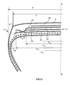
- the crown reinforcement is itself capped with a tread 6.
- the maximum axial width S of the tire is equal to 317 mm.
- the axial width L 41 of the first working layer 41 is equal to 252 mm.
- the axial width L 43 of the second working layer 43 is equal to 232 mm.
- the difference between the widths L 41 and L 43 is equal to 15 mm.
- the axial width L 42 of the layer of circumferential reinforcing elements 42 is equal to 194 mm.
- the last crown ply 44 has a width L 44 equal to 124 mm.
- the tensile modulus of elasticity at 10% elongation of the calendering layers of each of the working layers 41 and 43 is equal to 6 MPa.
- the tire 1 differs from that shown on the figure 1 in that the two working layers 41 and 43 are on each side of the equatorial plane and axially in the extension of the layer of reinforcing elements circumferences 42, coupled over an axial width 1: the cables of the first working layer 41 and the cables of the second working layer 43, over the axial coupling width 1 of the two layers, are separated radially from each other by a layer of gum, whose thickness is minimal and corresponds to twice the thickness of the rubbery calendering layer of 9.28 non-shrunk metal cables which is formed each working layer 41, 43, 0.8 mm. On the remaining width common to the two working layers, the two working layers 41, 43 are separated by a layer of rubber mix.
- Tests have been carried out with different tires made according to the invention in accordance with the representation of the figure 1 and compared with a tire a reference tire T1 having no layers of circumferential reinforcing elements, whose tensile elastic moduli at 10% elongation of the calenders of the working crown layers are greater than 8.5 MPa and whose values of tan ( ⁇ ) max of the calendars of the working crown layers are greater than 0.100.
- the calendars of the working layers consist of the mixture R1.
Landscapes
- Engineering & Computer Science (AREA)
- Mechanical Engineering (AREA)
- Tires In General (AREA)
- Compositions Of Macromolecular Compounds (AREA)
Applications Claiming Priority (2)
| Application Number | Priority Date | Filing Date | Title |
|---|---|---|---|
| FR1159244A FR2981299B1 (fr) | 2011-10-13 | 2011-10-13 | Pneumatique comportant une couche d'elements de renforcement circonferentiels |
| PCT/EP2012/070241 WO2013053880A1 (fr) | 2011-10-13 | 2012-10-12 | Pneumatique comportant une couche d'elements de renforcement circonferentiels |
Publications (2)
| Publication Number | Publication Date |
|---|---|
| EP2766202A1 EP2766202A1 (fr) | 2014-08-20 |
| EP2766202B1 true EP2766202B1 (fr) | 2015-12-30 |
Family
ID=47010607
Family Applications (1)
| Application Number | Title | Priority Date | Filing Date |
|---|---|---|---|
| EP12770495.5A Active EP2766202B1 (fr) | 2011-10-13 | 2012-10-12 | Pneumatique comportant une couche d'elements de renforcement circonferentiels |
Country Status (8)
Families Citing this family (17)
| Publication number | Priority date | Publication date | Assignee | Title |
|---|---|---|---|---|
| FR3038543B1 (fr) * | 2015-07-06 | 2017-07-21 | Michelin & Cie | Dispositif de type pneumatique pour vehicule |
| FR3045483B1 (fr) * | 2015-12-16 | 2017-12-22 | Michelin & Cie | Pneumatique presentant des proprietes d'usure et de resistance au roulement ameliorees |
| WO2017175675A1 (ja) * | 2016-04-08 | 2017-10-12 | 横浜ゴム株式会社 | 空気入りタイヤ |
| FR3051397B1 (fr) * | 2016-05-20 | 2018-05-11 | Compagnie Generale Des Etablissements Michelin | Pneumatique presentant une couche de protection avec des proprietes d’endurance ameliorees |
| FR3051398A1 (fr) * | 2016-05-20 | 2017-11-24 | Michelin & Cie | Pneumatique presentant une couche de protection avec des proprietes d’endurance ameliorees |
| KR102060640B1 (ko) | 2016-09-09 | 2019-12-30 | 주식회사 엘지화학 | 알루미노실리케이트 입자를 포함한 고무 보강재 및 이를 포함한 타이어용 고무 조성물 |
| FR3059597A1 (fr) * | 2016-12-05 | 2018-06-08 | Compagnie Generale Des Etablissements Michelin | Pneumatique comportant une armature de sommet allegee |
| FR3059598A1 (fr) * | 2016-12-05 | 2018-06-08 | Compagnie Generale Des Etablissements Michelin | Pneumatique comportant une armature de sommet allegee |
| FR3069190A1 (fr) * | 2017-07-21 | 2019-01-25 | Compagnie Generale Des Etablissements Michelin | Pneumatique presentant des proprietes d'usure et de resistance au roulement ameliorees |
| JP6946875B2 (ja) * | 2017-09-08 | 2021-10-13 | 住友ゴム工業株式会社 | 空気入りタイヤ |
| US20200361242A1 (en) * | 2017-11-08 | 2020-11-19 | Compagnie Generale Des Etablissements Michelin | Pneumatic Tire Having a Lightweight Crown Reinforcement |
| WO2019097140A1 (fr) * | 2017-11-17 | 2019-05-23 | Compagnie Generale Des Etablissements Michelin | Pneumatique presentant une couche d'armature de carcasse avec des proprietes d'endurance ameliorees |
| FR3079838B1 (fr) * | 2018-04-09 | 2020-12-18 | Michelin & Cie | Composition de caoutchouc comprenant une charge renforcante a faible surface specifique |
| FR3124113B1 (fr) | 2021-06-17 | 2023-07-14 | Michelin & Cie | Procédé et dispositif de traitement thermique d’un pneumatique presentant des propriétés de résistance au roulement ameliorées |
| FR3134539B1 (fr) * | 2022-04-14 | 2024-08-16 | Michelin & Cie | Pneumatique avec une armature de sommet simplifiée |
| FR3135918A1 (fr) * | 2022-05-25 | 2023-12-01 | Compagnie Generale Des Etablissements Michelin | Pneumatique avec une armature de sommet simplifiée en aramide |
| FR3137018A1 (fr) * | 2022-06-28 | 2023-12-29 | Compagnie Generale Des Etablissements Michelin | Pneumatique simplifié avec une armature de carcasse frettée |
Family Cites Families (14)
| Publication number | Priority date | Publication date | Assignee | Title |
|---|---|---|---|---|
| US2643273A (en) * | 1950-03-18 | 1953-06-23 | Nat Standard Co | Method of securing rubber adhesion to metal and composition therefor |
| FR1389428A (fr) | 1963-07-19 | 1965-02-19 | Pneumatiques, Caoutchouc Manufacture Et Plastiques Kleber Colombes | Pneumatique pour véhicule de forte charge |
| DE2313586A1 (de) | 1973-03-19 | 1974-09-26 | Uniroyal Ag | Fahrzeugluftreifen, insbesondere fuer lastkraftwagen |
| FR2729671B1 (fr) * | 1995-01-20 | 1997-04-18 | Michelin & Cie | Enveloppe de pneumatique a base de silice precipitee presentant une resistance au roulement amelioree |
| US5883179A (en) | 1995-10-25 | 1999-03-16 | The Yokohama Rubber Co., Ltd. | Rubber composition comprising carbon black surface treated with silica |
| FR2770458B1 (fr) | 1997-11-05 | 1999-12-03 | Michelin & Cie | Armature de sommet pour pneumatique "poids-lours" |
| DE60006166T2 (de) * | 1999-12-30 | 2004-07-22 | Société de Technologie Michelin | Kautschukzusammensetzung für reifen mit einem kupplungsmittel (wesiser füllstoff/dienelastomer), das durch einen thermisch initierbaren radikalstarter aktiviert wird |
| ATE362958T1 (de) * | 2001-01-02 | 2007-06-15 | Michelin Soc Tech | Kautschukmischung auf der basis eines dienelastomers und eines verstärkenden siliciumcarbids |
| DE10213289A1 (de) * | 2001-03-30 | 2002-11-14 | Yokohama Rubber Co Ltd | Elastomer-und-Stahlkord-Verbundwerkstoff und Prozess zur Herstellung desselben |
| CN1750944B (zh) | 2003-02-17 | 2011-08-17 | 米其林技术公司 | 用于子午线轮胎的胎冠加强件 |
| RU2335410C2 (ru) * | 2003-07-18 | 2008-10-10 | Сосьете Де Текноложи Мишлен | Пневматическая шина для тяжелых транспортных средств |
| FR2857620B1 (fr) * | 2003-07-18 | 2005-08-19 | Michelin Soc Tech | Pneumatique pour vehicules lourds |
| FR2873721A1 (fr) | 2004-08-02 | 2006-02-03 | Michelin Soc Tech | Cable a couches pour armature de sommet de pneumatique |
| FR2925922B1 (fr) * | 2007-12-28 | 2009-12-18 | Soc Tech Michelin | Cable a couches pour ceinture de pneumatique |
-
2011
- 2011-10-13 FR FR1159244A patent/FR2981299B1/fr not_active Expired - Fee Related
-
2012
- 2012-10-12 WO PCT/EP2012/070241 patent/WO2013053880A1/fr active Application Filing
- 2012-10-12 JP JP2014535100A patent/JP6409214B2/ja not_active Expired - Fee Related
- 2012-10-12 RU RU2014118763/11A patent/RU2014118763A/ru not_active Application Discontinuation
- 2012-10-12 US US14/351,820 patent/US20140261951A1/en not_active Abandoned
- 2012-10-12 BR BR112014008930-2A patent/BR112014008930B1/pt active IP Right Grant
- 2012-10-12 CN CN201280049984.1A patent/CN103874587B/zh active Active
- 2012-10-12 EP EP12770495.5A patent/EP2766202B1/fr active Active
Also Published As
| Publication number | Publication date |
|---|---|
| RU2014118763A (ru) | 2015-11-20 |
| JP2014534111A (ja) | 2014-12-18 |
| FR2981299B1 (fr) | 2014-07-11 |
| CN103874587A (zh) | 2014-06-18 |
| WO2013053880A1 (fr) | 2013-04-18 |
| US20140261951A1 (en) | 2014-09-18 |
| BR112014008930A2 (pt) | 2017-04-25 |
| EP2766202A1 (fr) | 2014-08-20 |
| BR112014008930A8 (pt) | 2017-12-26 |
| CN103874587B (zh) | 2018-04-17 |
| BR112014008930B1 (pt) | 2020-09-15 |
| FR2981299A1 (fr) | 2013-04-19 |
| JP6409214B2 (ja) | 2018-10-24 |
Similar Documents
| Publication | Publication Date | Title |
|---|---|---|
| EP2766201B1 (fr) | Pneumatique comportant une couche d'elements de renforcement circonferentiels | |
| EP2766204B1 (fr) | Pneumatique comportant une couche d'elements de renforcement circonferentiels | |
| EP2766202B1 (fr) | Pneumatique comportant une couche d'elements de renforcement circonferentiels | |
| EP2788201B1 (fr) | Pneumatique comportant une couche d'elements de renforcement circonferentiels | |
| EP3160763B1 (fr) | Pneumatique comportant une couche d'elements de renforcement circonferentiels | |
| EP2788202B1 (fr) | Pneumatique comportant une couche d'elements de renforcement circonferentiels | |
| EP3160762B1 (fr) | Pneumatique comportant une couche d'elements de renforcement circonferentiels | |
| EP3297851B1 (fr) | Pneumatique comportant des couches de travail constituees de fils unitaires | |
| EP3160766B1 (fr) | Pneumatique comportant une couche d'elements de renforcement circonferentiels | |
| EP3160761B1 (fr) | Pneumatique comportant une couche d'elements de renforcement circonferentiels | |
| EP3160765B1 (fr) | Pneumatique comportant une couche d'elements de renforcement circonferentiels | |
| EP3160770B1 (fr) | Pneumatique comportant une couche d'elements de renforcement circonferentiels | |
| EP3160768B1 (fr) | Pneumatique comportant une couche d'elements de renforcement circonferentiels | |
| EP3160764B1 (fr) | Pneumatique comportant une couche d'elements de renforcement circonferentiels | |
| EP3297852B1 (fr) | Pneumatique comportant des couches de travail constituees de fils unitaires | |
| WO2019197763A1 (fr) | Pneumatique allege comportant une couche d'elements de renforcement circonferentiels | |
| WO2017103437A1 (fr) | Pneumatique presentant des proprietes d'usure et de resistance au roulement ameliorees | |
| FR3089998A1 (fr) | Pneumatique allege comportant une couche d’elements de renforcement circonferentiels |
Legal Events
| Date | Code | Title | Description |
|---|---|---|---|
| PUAI | Public reference made under article 153(3) epc to a published international application that has entered the european phase |
Free format text: ORIGINAL CODE: 0009012 |
|
| 17P | Request for examination filed |
Effective date: 20140513 |
|
| AK | Designated contracting states |
Kind code of ref document: A1 Designated state(s): AL AT BE BG CH CY CZ DE DK EE ES FI FR GB GR HR HU IE IS IT LI LT LU LV MC MK MT NL NO PL PT RO RS SE SI SK SM TR |
|
| DAX | Request for extension of the european patent (deleted) | ||
| GRAP | Despatch of communication of intention to grant a patent |
Free format text: ORIGINAL CODE: EPIDOSNIGR1 |
|
| INTG | Intention to grant announced |
Effective date: 20150918 |
|
| GRAS | Grant fee paid |
Free format text: ORIGINAL CODE: EPIDOSNIGR3 |
|
| GRAA | (expected) grant |
Free format text: ORIGINAL CODE: 0009210 |
|
| AK | Designated contracting states |
Kind code of ref document: B1 Designated state(s): AL AT BE BG CH CY CZ DE DK EE ES FI FR GB GR HR HU IE IS IT LI LT LU LV MC MK MT NL NO PL PT RO RS SE SI SK SM TR |
|
| REG | Reference to a national code |
Ref country code: GB Ref legal event code: FG4D Free format text: NOT ENGLISH |
|
| REG | Reference to a national code |
Ref country code: CH Ref legal event code: EP |
|
| REG | Reference to a national code |
Ref country code: AT Ref legal event code: REF Ref document number: 767283 Country of ref document: AT Kind code of ref document: T Effective date: 20160115 |
|
| REG | Reference to a national code |
Ref country code: IE Ref legal event code: FG4D Free format text: LANGUAGE OF EP DOCUMENT: FRENCH |
|
| REG | Reference to a national code |
Ref country code: DE Ref legal event code: R096 Ref document number: 602012013440 Country of ref document: DE |
|
| REG | Reference to a national code |
Ref country code: NL Ref legal event code: FP |
|
| REG | Reference to a national code |
Ref country code: LT Ref legal event code: MG4D |
|
| PG25 | Lapsed in a contracting state [announced via postgrant information from national office to epo] |
Ref country code: NO Free format text: LAPSE BECAUSE OF FAILURE TO SUBMIT A TRANSLATION OF THE DESCRIPTION OR TO PAY THE FEE WITHIN THE PRESCRIBED TIME-LIMIT Effective date: 20160330 Ref country code: HR Free format text: LAPSE BECAUSE OF FAILURE TO SUBMIT A TRANSLATION OF THE DESCRIPTION OR TO PAY THE FEE WITHIN THE PRESCRIBED TIME-LIMIT Effective date: 20151230 Ref country code: LT Free format text: LAPSE BECAUSE OF FAILURE TO SUBMIT A TRANSLATION OF THE DESCRIPTION OR TO PAY THE FEE WITHIN THE PRESCRIBED TIME-LIMIT Effective date: 20151230 |
|
| REG | Reference to a national code |
Ref country code: AT Ref legal event code: MK05 Ref document number: 767283 Country of ref document: AT Kind code of ref document: T Effective date: 20151230 |
|
| PG25 | Lapsed in a contracting state [announced via postgrant information from national office to epo] |
Ref country code: GR Free format text: LAPSE BECAUSE OF FAILURE TO SUBMIT A TRANSLATION OF THE DESCRIPTION OR TO PAY THE FEE WITHIN THE PRESCRIBED TIME-LIMIT Effective date: 20160331 Ref country code: SE Free format text: LAPSE BECAUSE OF FAILURE TO SUBMIT A TRANSLATION OF THE DESCRIPTION OR TO PAY THE FEE WITHIN THE PRESCRIBED TIME-LIMIT Effective date: 20151230 Ref country code: FI Free format text: LAPSE BECAUSE OF FAILURE TO SUBMIT A TRANSLATION OF THE DESCRIPTION OR TO PAY THE FEE WITHIN THE PRESCRIBED TIME-LIMIT Effective date: 20151230 Ref country code: LV Free format text: LAPSE BECAUSE OF FAILURE TO SUBMIT A TRANSLATION OF THE DESCRIPTION OR TO PAY THE FEE WITHIN THE PRESCRIBED TIME-LIMIT Effective date: 20151230 Ref country code: RS Free format text: LAPSE BECAUSE OF FAILURE TO SUBMIT A TRANSLATION OF THE DESCRIPTION OR TO PAY THE FEE WITHIN THE PRESCRIBED TIME-LIMIT Effective date: 20151230 |
|
| PG25 | Lapsed in a contracting state [announced via postgrant information from national office to epo] |
Ref country code: ES Free format text: LAPSE BECAUSE OF FAILURE TO SUBMIT A TRANSLATION OF THE DESCRIPTION OR TO PAY THE FEE WITHIN THE PRESCRIBED TIME-LIMIT Effective date: 20151230 Ref country code: IT Free format text: LAPSE BECAUSE OF FAILURE TO SUBMIT A TRANSLATION OF THE DESCRIPTION OR TO PAY THE FEE WITHIN THE PRESCRIBED TIME-LIMIT Effective date: 20151230 Ref country code: CZ Free format text: LAPSE BECAUSE OF FAILURE TO SUBMIT A TRANSLATION OF THE DESCRIPTION OR TO PAY THE FEE WITHIN THE PRESCRIBED TIME-LIMIT Effective date: 20151230 |
|
| PG25 | Lapsed in a contracting state [announced via postgrant information from national office to epo] |
Ref country code: PT Free format text: LAPSE BECAUSE OF FAILURE TO SUBMIT A TRANSLATION OF THE DESCRIPTION OR TO PAY THE FEE WITHIN THE PRESCRIBED TIME-LIMIT Effective date: 20160502 Ref country code: AT Free format text: LAPSE BECAUSE OF FAILURE TO SUBMIT A TRANSLATION OF THE DESCRIPTION OR TO PAY THE FEE WITHIN THE PRESCRIBED TIME-LIMIT Effective date: 20151230 Ref country code: EE Free format text: LAPSE BECAUSE OF FAILURE TO SUBMIT A TRANSLATION OF THE DESCRIPTION OR TO PAY THE FEE WITHIN THE PRESCRIBED TIME-LIMIT Effective date: 20151230 Ref country code: IS Free format text: LAPSE BECAUSE OF FAILURE TO SUBMIT A TRANSLATION OF THE DESCRIPTION OR TO PAY THE FEE WITHIN THE PRESCRIBED TIME-LIMIT Effective date: 20160430 Ref country code: RO Free format text: LAPSE BECAUSE OF FAILURE TO SUBMIT A TRANSLATION OF THE DESCRIPTION OR TO PAY THE FEE WITHIN THE PRESCRIBED TIME-LIMIT Effective date: 20151230 Ref country code: SM Free format text: LAPSE BECAUSE OF FAILURE TO SUBMIT A TRANSLATION OF THE DESCRIPTION OR TO PAY THE FEE WITHIN THE PRESCRIBED TIME-LIMIT Effective date: 20151230 Ref country code: PL Free format text: LAPSE BECAUSE OF FAILURE TO SUBMIT A TRANSLATION OF THE DESCRIPTION OR TO PAY THE FEE WITHIN THE PRESCRIBED TIME-LIMIT Effective date: 20151230 Ref country code: SK Free format text: LAPSE BECAUSE OF FAILURE TO SUBMIT A TRANSLATION OF THE DESCRIPTION OR TO PAY THE FEE WITHIN THE PRESCRIBED TIME-LIMIT Effective date: 20151230 |
|
| REG | Reference to a national code |
Ref country code: DE Ref legal event code: R097 Ref document number: 602012013440 Country of ref document: DE |
|
| REG | Reference to a national code |
Ref country code: FR Ref legal event code: PLFP Year of fee payment: 5 |
|
| PG25 | Lapsed in a contracting state [announced via postgrant information from national office to epo] |
Ref country code: DK Free format text: LAPSE BECAUSE OF FAILURE TO SUBMIT A TRANSLATION OF THE DESCRIPTION OR TO PAY THE FEE WITHIN THE PRESCRIBED TIME-LIMIT Effective date: 20151230 |
|
| PLBE | No opposition filed within time limit |
Free format text: ORIGINAL CODE: 0009261 |
|
| STAA | Information on the status of an ep patent application or granted ep patent |
Free format text: STATUS: NO OPPOSITION FILED WITHIN TIME LIMIT |
|
| 26N | No opposition filed |
Effective date: 20161003 |
|
| PG25 | Lapsed in a contracting state [announced via postgrant information from national office to epo] |
Ref country code: SI Free format text: LAPSE BECAUSE OF FAILURE TO SUBMIT A TRANSLATION OF THE DESCRIPTION OR TO PAY THE FEE WITHIN THE PRESCRIBED TIME-LIMIT Effective date: 20151230 Ref country code: BE Free format text: LAPSE BECAUSE OF NON-PAYMENT OF DUE FEES Effective date: 20161031 |
|
| REG | Reference to a national code |
Ref country code: CH Ref legal event code: PL |
|
| GBPC | Gb: european patent ceased through non-payment of renewal fee |
Effective date: 20161012 |
|
| REG | Reference to a national code |
Ref country code: IE Ref legal event code: MM4A |
|
| PG25 | Lapsed in a contracting state [announced via postgrant information from national office to epo] |
Ref country code: CH Free format text: LAPSE BECAUSE OF NON-PAYMENT OF DUE FEES Effective date: 20161031 Ref country code: GB Free format text: LAPSE BECAUSE OF NON-PAYMENT OF DUE FEES Effective date: 20161012 Ref country code: LI Free format text: LAPSE BECAUSE OF NON-PAYMENT OF DUE FEES Effective date: 20161031 |
|
| PG25 | Lapsed in a contracting state [announced via postgrant information from national office to epo] |
Ref country code: LU Free format text: LAPSE BECAUSE OF NON-PAYMENT OF DUE FEES Effective date: 20161012 |
|
| REG | Reference to a national code |
Ref country code: FR Ref legal event code: PLFP Year of fee payment: 6 |
|
| PG25 | Lapsed in a contracting state [announced via postgrant information from national office to epo] |
Ref country code: IE Free format text: LAPSE BECAUSE OF NON-PAYMENT OF DUE FEES Effective date: 20161012 |
|
| REG | Reference to a national code |
Ref country code: BE Ref legal event code: MM Effective date: 20161031 |
|
| PG25 | Lapsed in a contracting state [announced via postgrant information from national office to epo] |
Ref country code: HU Free format text: LAPSE BECAUSE OF FAILURE TO SUBMIT A TRANSLATION OF THE DESCRIPTION OR TO PAY THE FEE WITHIN THE PRESCRIBED TIME-LIMIT; INVALID AB INITIO Effective date: 20121012 |
|
| PG25 | Lapsed in a contracting state [announced via postgrant information from national office to epo] |
Ref country code: CY Free format text: LAPSE BECAUSE OF FAILURE TO SUBMIT A TRANSLATION OF THE DESCRIPTION OR TO PAY THE FEE WITHIN THE PRESCRIBED TIME-LIMIT Effective date: 20151230 Ref country code: MC Free format text: LAPSE BECAUSE OF FAILURE TO SUBMIT A TRANSLATION OF THE DESCRIPTION OR TO PAY THE FEE WITHIN THE PRESCRIBED TIME-LIMIT Effective date: 20151230 Ref country code: MT Free format text: LAPSE BECAUSE OF FAILURE TO SUBMIT A TRANSLATION OF THE DESCRIPTION OR TO PAY THE FEE WITHIN THE PRESCRIBED TIME-LIMIT Effective date: 20151230 Ref country code: MK Free format text: LAPSE BECAUSE OF FAILURE TO SUBMIT A TRANSLATION OF THE DESCRIPTION OR TO PAY THE FEE WITHIN THE PRESCRIBED TIME-LIMIT Effective date: 20151230 |
|
| PG25 | Lapsed in a contracting state [announced via postgrant information from national office to epo] |
Ref country code: BG Free format text: LAPSE BECAUSE OF FAILURE TO SUBMIT A TRANSLATION OF THE DESCRIPTION OR TO PAY THE FEE WITHIN THE PRESCRIBED TIME-LIMIT Effective date: 20151230 |
|
| REG | Reference to a national code |
Ref country code: FR Ref legal event code: PLFP Year of fee payment: 7 |
|
| PG25 | Lapsed in a contracting state [announced via postgrant information from national office to epo] |
Ref country code: TR Free format text: LAPSE BECAUSE OF FAILURE TO SUBMIT A TRANSLATION OF THE DESCRIPTION OR TO PAY THE FEE WITHIN THE PRESCRIBED TIME-LIMIT Effective date: 20151230 Ref country code: AL Free format text: LAPSE BECAUSE OF FAILURE TO SUBMIT A TRANSLATION OF THE DESCRIPTION OR TO PAY THE FEE WITHIN THE PRESCRIBED TIME-LIMIT Effective date: 20151230 |
|
| PGFP | Annual fee paid to national office [announced via postgrant information from national office to epo] |
Ref country code: NL Payment date: 20191021 Year of fee payment: 8 |
|
| REG | Reference to a national code |
Ref country code: NL Ref legal event code: MM Effective date: 20201101 |
|
| PG25 | Lapsed in a contracting state [announced via postgrant information from national office to epo] |
Ref country code: NL Free format text: LAPSE BECAUSE OF NON-PAYMENT OF DUE FEES Effective date: 20201101 |
|
| REG | Reference to a national code |
Ref country code: DE Ref legal event code: R081 Ref document number: 602012013440 Country of ref document: DE Owner name: COMPAGNIE GENERALE DES ETABLISSEMENTS MICHELIN, FR Free format text: FORMER OWNERS: COMPAGNIE GENERALE DES ETABLISSEMENTS MICHELIN, CLERMONT-FERRAND, FR; MICHELIN RECHERCHE ET TECHNIQUE S.A., GRANGES-PACCOT, CH |
|
| PGFP | Annual fee paid to national office [announced via postgrant information from national office to epo] |
Ref country code: DE Payment date: 20241021 Year of fee payment: 13 |
|
| PGFP | Annual fee paid to national office [announced via postgrant information from national office to epo] |
Ref country code: FR Payment date: 20241021 Year of fee payment: 13 |