EP2766202B1 - Tyre comprising a layer of circumferential reinforcing elements - Google Patents
Tyre comprising a layer of circumferential reinforcing elements Download PDFInfo
- Publication number
- EP2766202B1 EP2766202B1 EP12770495.5A EP12770495A EP2766202B1 EP 2766202 B1 EP2766202 B1 EP 2766202B1 EP 12770495 A EP12770495 A EP 12770495A EP 2766202 B1 EP2766202 B1 EP 2766202B1
- Authority
- EP
- European Patent Office
- Prior art keywords
- layer
- reinforcing elements
- layers
- tyre
- working
- Prior art date
- Legal status (The legal status is an assumption and is not a legal conclusion. Google has not performed a legal analysis and makes no representation as to the accuracy of the status listed.)
- Active
Links
- 230000003014 reinforcing effect Effects 0.000 title claims description 97
- 230000002787 reinforcement Effects 0.000 claims description 52
- 239000000203 mixture Substances 0.000 claims description 50
- 229920001971 elastomer Polymers 0.000 claims description 46
- 239000005060 rubber Substances 0.000 claims description 41
- 229910052751 metal Inorganic materials 0.000 claims description 26
- 239000002184 metal Substances 0.000 claims description 22
- 238000003490 calendering Methods 0.000 claims description 21
- VYPSYNLAJGMNEJ-UHFFFAOYSA-N Silicium dioxide Chemical compound O=[Si]=O VYPSYNLAJGMNEJ-UHFFFAOYSA-N 0.000 claims description 16
- 239000006229 carbon black Substances 0.000 claims description 15
- 235000019241 carbon black Nutrition 0.000 claims description 15
- 229920003244 diene elastomer Polymers 0.000 claims description 11
- 239000012763 reinforcing filler Substances 0.000 claims description 8
- 244000043261 Hevea brasiliensis Species 0.000 claims description 7
- 239000004914 cyclooctane Substances 0.000 claims description 7
- 229920003052 natural elastomer Polymers 0.000 claims description 7
- 229920001194 natural rubber Polymers 0.000 claims description 7
- 239000000377 silicon dioxide Substances 0.000 claims description 7
- 229920003051 synthetic elastomer Polymers 0.000 claims description 7
- 229910020175 SiOH Inorganic materials 0.000 claims description 6
- 239000000945 filler Substances 0.000 claims description 6
- 241000872198 Serjania polyphylla Species 0.000 claims description 4
- PNEYBMLMFCGWSK-UHFFFAOYSA-N aluminium oxide Inorganic materials [O-2].[O-2].[O-2].[Al+3].[Al+3] PNEYBMLMFCGWSK-UHFFFAOYSA-N 0.000 claims description 4
- 229910000323 aluminium silicate Inorganic materials 0.000 claims description 4
- 239000011324 bead Substances 0.000 claims description 4
- 230000015572 biosynthetic process Effects 0.000 claims description 4
- 229920006395 saturated elastomer Polymers 0.000 claims description 4
- 238000003786 synthesis reaction Methods 0.000 claims description 4
- 125000000524 functional group Chemical group 0.000 claims description 2
- 230000001747 exhibiting effect Effects 0.000 claims 2
- 230000001681 protective effect Effects 0.000 claims 1
- 239000010410 layer Substances 0.000 description 182
- 238000012360 testing method Methods 0.000 description 15
- 238000005096 rolling process Methods 0.000 description 13
- 229910000831 Steel Inorganic materials 0.000 description 8
- 239000010959 steel Substances 0.000 description 8
- 238000005259 measurement Methods 0.000 description 7
- OKTJSMMVPCPJKN-UHFFFAOYSA-N Carbon Chemical compound [C] OKTJSMMVPCPJKN-UHFFFAOYSA-N 0.000 description 6
- 239000003795 chemical substances by application Substances 0.000 description 6
- 238000007906 compression Methods 0.000 description 6
- 230000006835 compression Effects 0.000 description 6
- 230000036316 preload Effects 0.000 description 6
- 239000011241 protective layer Substances 0.000 description 6
- 150000001875 compounds Chemical class 0.000 description 5
- 239000000806 elastomer Substances 0.000 description 5
- 230000008878 coupling Effects 0.000 description 4
- 238000010168 coupling process Methods 0.000 description 4
- 238000005859 coupling reaction Methods 0.000 description 4
- 238000004132 cross linking Methods 0.000 description 4
- 238000013461 design Methods 0.000 description 4
- 239000000463 material Substances 0.000 description 4
- 229910000975 Carbon steel Inorganic materials 0.000 description 3
- 230000004308 accommodation Effects 0.000 description 3
- QVGXLLKOCUKJST-UHFFFAOYSA-N atomic oxygen Chemical compound [O] QVGXLLKOCUKJST-UHFFFAOYSA-N 0.000 description 3
- 229910052799 carbon Inorganic materials 0.000 description 3
- 239000010962 carbon steel Substances 0.000 description 3
- 150000001868 cobalt Chemical class 0.000 description 3
- 238000010276 construction Methods 0.000 description 3
- 238000005336 cracking Methods 0.000 description 3
- 238000005520 cutting process Methods 0.000 description 3
- 150000001993 dienes Chemical class 0.000 description 3
- 230000000694 effects Effects 0.000 description 3
- 230000000670 limiting effect Effects 0.000 description 3
- 239000003921 oil Substances 0.000 description 3
- 229910052760 oxygen Inorganic materials 0.000 description 3
- 239000001301 oxygen Substances 0.000 description 3
- 230000002829 reductive effect Effects 0.000 description 3
- 238000004073 vulcanization Methods 0.000 description 3
- 238000004804 winding Methods 0.000 description 3
- MYRTYDVEIRVNKP-UHFFFAOYSA-N 1,2-Divinylbenzene Chemical compound C=CC1=CC=CC=C1C=C MYRTYDVEIRVNKP-UHFFFAOYSA-N 0.000 description 2
- 241000447437 Gerreidae Species 0.000 description 2
- RRHGJUQNOFWUDK-UHFFFAOYSA-N Isoprene Chemical compound CC(=C)C=C RRHGJUQNOFWUDK-UHFFFAOYSA-N 0.000 description 2
- 239000005062 Polybutadiene Substances 0.000 description 2
- NINIDFKCEFEMDL-UHFFFAOYSA-N Sulfur Chemical compound [S] NINIDFKCEFEMDL-UHFFFAOYSA-N 0.000 description 2
- XLOMVQKBTHCTTD-UHFFFAOYSA-N Zinc monoxide Chemical compound [Zn]=O XLOMVQKBTHCTTD-UHFFFAOYSA-N 0.000 description 2
- 239000003963 antioxidant agent Substances 0.000 description 2
- 230000002238 attenuated effect Effects 0.000 description 2
- 150000001721 carbon Chemical class 0.000 description 2
- 229920001577 copolymer Polymers 0.000 description 2
- 239000007822 coupling agent Substances 0.000 description 2
- 238000010586 diagram Methods 0.000 description 2
- 238000006073 displacement reaction Methods 0.000 description 2
- 238000000034 method Methods 0.000 description 2
- 239000000178 monomer Substances 0.000 description 2
- 230000003647 oxidation Effects 0.000 description 2
- 238000007254 oxidation reaction Methods 0.000 description 2
- 229920001195 polyisoprene Polymers 0.000 description 2
- 238000006116 polymerization reaction Methods 0.000 description 2
- 230000009467 reduction Effects 0.000 description 2
- 230000000717 retained effect Effects 0.000 description 2
- 229920003048 styrene butadiene rubber Polymers 0.000 description 2
- 229910052717 sulfur Inorganic materials 0.000 description 2
- 239000011593 sulfur Substances 0.000 description 2
- OWRCNXZUPFZXOS-UHFFFAOYSA-N 1,3-diphenylguanidine Chemical compound C=1C=CC=CC=1NC(=N)NC1=CC=CC=C1 OWRCNXZUPFZXOS-UHFFFAOYSA-N 0.000 description 1
- OVSKIKFHRZPJSS-UHFFFAOYSA-N 2,4-D Chemical compound OC(=O)COC1=CC=C(Cl)C=C1Cl OVSKIKFHRZPJSS-UHFFFAOYSA-N 0.000 description 1
- 238000004438 BET method Methods 0.000 description 1
- 239000004606 Fillers/Extenders Substances 0.000 description 1
- 101000826116 Homo sapiens Single-stranded DNA-binding protein 3 Proteins 0.000 description 1
- BPQQTUXANYXVAA-UHFFFAOYSA-N Orthosilicate Chemical compound [O-][Si]([O-])([O-])[O-] BPQQTUXANYXVAA-UHFFFAOYSA-N 0.000 description 1
- 239000002202 Polyethylene glycol Substances 0.000 description 1
- BLRPTPMANUNPDV-UHFFFAOYSA-N Silane Chemical compound [SiH4] BLRPTPMANUNPDV-UHFFFAOYSA-N 0.000 description 1
- 102100023008 Single-stranded DNA-binding protein 3 Human genes 0.000 description 1
- 229920002472 Starch Polymers 0.000 description 1
- 235000021355 Stearic acid Nutrition 0.000 description 1
- 239000002174 Styrene-butadiene Substances 0.000 description 1
- 241001080024 Telles Species 0.000 description 1
- REUQOSNMSWLNPD-UHFFFAOYSA-N [2-(diethylamino)phenyl]-phenylmethanone Chemical compound CCN(CC)C1=CC=CC=C1C(=O)C1=CC=CC=C1 REUQOSNMSWLNPD-UHFFFAOYSA-N 0.000 description 1
- 238000010521 absorption reaction Methods 0.000 description 1
- 239000000370 acceptor Substances 0.000 description 1
- 239000002253 acid Substances 0.000 description 1
- 230000009471 action Effects 0.000 description 1
- 239000002318 adhesion promoter Substances 0.000 description 1
- 125000003545 alkoxy group Chemical group 0.000 description 1
- 229910045601 alloy Inorganic materials 0.000 description 1
- 239000000956 alloy Substances 0.000 description 1
- 230000004075 alteration Effects 0.000 description 1
- HIGRAKVNKLCVCA-UHFFFAOYSA-N alumine Chemical compound C1=CC=[Al]C=C1 HIGRAKVNKLCVCA-UHFFFAOYSA-N 0.000 description 1
- 229910052782 aluminium Inorganic materials 0.000 description 1
- -1 aluminum compound Chemical class 0.000 description 1
- ANBBXQWFNXMHLD-UHFFFAOYSA-N aluminum;sodium;oxygen(2-) Chemical compound [O-2].[O-2].[Na+].[Al+3] ANBBXQWFNXMHLD-UHFFFAOYSA-N 0.000 description 1
- 150000001412 amines Chemical group 0.000 description 1
- 230000003712 anti-aging effect Effects 0.000 description 1
- 230000003078 antioxidant effect Effects 0.000 description 1
- 239000007900 aqueous suspension Substances 0.000 description 1
- 230000000712 assembly Effects 0.000 description 1
- 238000000429 assembly Methods 0.000 description 1
- 230000000903 blocking effect Effects 0.000 description 1
- 239000006085 branching agent Substances 0.000 description 1
- RTACIUYXLGWTAE-UHFFFAOYSA-N buta-1,3-diene;2-methylbuta-1,3-diene;styrene Chemical compound C=CC=C.CC(=C)C=C.C=CC1=CC=CC=C1 RTACIUYXLGWTAE-UHFFFAOYSA-N 0.000 description 1
- 239000011203 carbon fibre reinforced carbon Substances 0.000 description 1
- 150000004649 carbonic acid derivatives Chemical class 0.000 description 1
- 125000003178 carboxy group Chemical group [H]OC(*)=O 0.000 description 1
- 230000015556 catabolic process Effects 0.000 description 1
- 230000008859 change Effects 0.000 description 1
- 238000012512 characterization method Methods 0.000 description 1
- 239000011248 coating agent Substances 0.000 description 1
- 239000002131 composite material Substances 0.000 description 1
- 239000000470 constituent Substances 0.000 description 1
- 238000010411 cooking Methods 0.000 description 1
- 230000007797 corrosion Effects 0.000 description 1
- 238000005260 corrosion Methods 0.000 description 1
- 230000003247 decreasing effect Effects 0.000 description 1
- 230000007850 degeneration Effects 0.000 description 1
- 238000006731 degradation reaction Methods 0.000 description 1
- 238000011161 development Methods 0.000 description 1
- 125000000118 dimethyl group Chemical group [H]C([H])([H])* 0.000 description 1
- HNPSIPDUKPIQMN-UHFFFAOYSA-N dioxosilane;oxo(oxoalumanyloxy)alumane Chemical compound O=[Si]=O.O=[Al]O[Al]=O HNPSIPDUKPIQMN-UHFFFAOYSA-N 0.000 description 1
- 239000000839 emulsion Substances 0.000 description 1
- 229940082150 encore Drugs 0.000 description 1
- 238000001125 extrusion Methods 0.000 description 1
- 150000002191 fatty alcohols Chemical class 0.000 description 1
- 230000002349 favourable effect Effects 0.000 description 1
- 238000009472 formulation Methods 0.000 description 1
- 239000000446 fuel Substances 0.000 description 1
- 229910021485 fumed silica Inorganic materials 0.000 description 1
- 238000007306 functionalization reaction Methods 0.000 description 1
- 238000010438 heat treatment Methods 0.000 description 1
- RSKGMYDENCAJEN-UHFFFAOYSA-N hexadecyl(trimethoxy)silane Chemical group CCCCCCCCCCCCCCCC[Si](OC)(OC)OC RSKGMYDENCAJEN-UHFFFAOYSA-N 0.000 description 1
- 229920001519 homopolymer Polymers 0.000 description 1
- 230000006872 improvement Effects 0.000 description 1
- 239000004615 ingredient Substances 0.000 description 1
- 239000011256 inorganic filler Substances 0.000 description 1
- 229910003475 inorganic filler Inorganic materials 0.000 description 1
- 239000012263 liquid product Substances 0.000 description 1
- 238000004519 manufacturing process Methods 0.000 description 1
- 239000011159 matrix material Substances 0.000 description 1
- 238000002844 melting Methods 0.000 description 1
- 230000008018 melting Effects 0.000 description 1
- 125000000325 methylidene group Chemical group [H]C([H])=* 0.000 description 1
- IUJLOAKJZQBENM-UHFFFAOYSA-N n-(1,3-benzothiazol-2-ylsulfanyl)-2-methylpropan-2-amine Chemical compound C1=CC=C2SC(SNC(C)(C)C)=NC2=C1 IUJLOAKJZQBENM-UHFFFAOYSA-N 0.000 description 1
- CMAUJSNXENPPOF-UHFFFAOYSA-N n-(1,3-benzothiazol-2-ylsulfanyl)-n-cyclohexylcyclohexanamine Chemical compound C1CCCCC1N(C1CCCCC1)SC1=NC2=CC=CC=C2S1 CMAUJSNXENPPOF-UHFFFAOYSA-N 0.000 description 1
- 239000012299 nitrogen atmosphere Substances 0.000 description 1
- QIQXTHQIDYTFRH-UHFFFAOYSA-N octadecanoic acid Chemical compound CCCCCCCCCCCCCCCCCC(O)=O QIQXTHQIDYTFRH-UHFFFAOYSA-N 0.000 description 1
- OQCDKBAXFALNLD-UHFFFAOYSA-N octadecanoic acid Natural products CCCCCCCC(C)CCCCCCCCC(O)=O OQCDKBAXFALNLD-UHFFFAOYSA-N 0.000 description 1
- 230000036961 partial effect Effects 0.000 description 1
- 239000004033 plastic Substances 0.000 description 1
- 229920003023 plastic Polymers 0.000 description 1
- 239000004014 plasticizer Substances 0.000 description 1
- 239000011120 plywood Substances 0.000 description 1
- 229920003192 poly(bis maleimide) Polymers 0.000 description 1
- 229920002857 polybutadiene Polymers 0.000 description 1
- 229920001223 polyethylene glycol Polymers 0.000 description 1
- 229920001021 polysulfide Polymers 0.000 description 1
- 239000005077 polysulfide Substances 0.000 description 1
- 150000008117 polysulfides Polymers 0.000 description 1
- 230000001737 promoting effect Effects 0.000 description 1
- 230000001698 pyrogenic effect Effects 0.000 description 1
- 229920005989 resin Polymers 0.000 description 1
- 239000011347 resin Substances 0.000 description 1
- 230000004044 response Effects 0.000 description 1
- 150000003839 salts Chemical class 0.000 description 1
- 238000000926 separation method Methods 0.000 description 1
- 229910000077 silane Inorganic materials 0.000 description 1
- 229910052710 silicon Inorganic materials 0.000 description 1
- 239000010703 silicon Substances 0.000 description 1
- 229920002545 silicone oil Polymers 0.000 description 1
- 239000002356 single layer Substances 0.000 description 1
- 229910001388 sodium aluminate Inorganic materials 0.000 description 1
- 239000002689 soil Substances 0.000 description 1
- 239000012265 solid product Substances 0.000 description 1
- 125000006850 spacer group Chemical group 0.000 description 1
- 239000010935 stainless steel Substances 0.000 description 1
- 229910001220 stainless steel Inorganic materials 0.000 description 1
- 239000008107 starch Substances 0.000 description 1
- 235000019698 starch Nutrition 0.000 description 1
- 239000008117 stearic acid Substances 0.000 description 1
- 238000005728 strengthening Methods 0.000 description 1
- 239000000126 substance Substances 0.000 description 1
- 229920001897 terpolymer Polymers 0.000 description 1
- VTHOKNTVYKTUPI-UHFFFAOYSA-N triethoxy-[3-(3-triethoxysilylpropyltetrasulfanyl)propyl]silane Chemical compound CCO[Si](OCC)(OCC)CCCSSSSCCC[Si](OCC)(OCC)OCC VTHOKNTVYKTUPI-UHFFFAOYSA-N 0.000 description 1
- QQQSFSZALRVCSZ-UHFFFAOYSA-N triethoxysilane Chemical compound CCO[SiH](OCC)OCC QQQSFSZALRVCSZ-UHFFFAOYSA-N 0.000 description 1
- 239000012936 vulcanization activator Substances 0.000 description 1
- 239000011787 zinc oxide Substances 0.000 description 1
Images

Classifications
-
- B—PERFORMING OPERATIONS; TRANSPORTING
- B60—VEHICLES IN GENERAL
- B60C—VEHICLE TYRES; TYRE INFLATION; TYRE CHANGING; CONNECTING VALVES TO INFLATABLE ELASTIC BODIES IN GENERAL; DEVICES OR ARRANGEMENTS RELATED TO TYRES
- B60C9/00—Reinforcements or ply arrangement of pneumatic tyres
- B60C9/18—Structure or arrangement of belts or breakers, crown-reinforcing or cushioning layers
- B60C9/20—Structure or arrangement of belts or breakers, crown-reinforcing or cushioning layers built-up from rubberised plies each having all cords arranged substantially parallel
- B60C9/2003—Structure or arrangement of belts or breakers, crown-reinforcing or cushioning layers built-up from rubberised plies each having all cords arranged substantially parallel characterised by the materials of the belt cords
- B60C9/2006—Structure or arrangement of belts or breakers, crown-reinforcing or cushioning layers built-up from rubberised plies each having all cords arranged substantially parallel characterised by the materials of the belt cords consisting of steel cord plies only
-
- B—PERFORMING OPERATIONS; TRANSPORTING
- B60—VEHICLES IN GENERAL
- B60C—VEHICLE TYRES; TYRE INFLATION; TYRE CHANGING; CONNECTING VALVES TO INFLATABLE ELASTIC BODIES IN GENERAL; DEVICES OR ARRANGEMENTS RELATED TO TYRES
- B60C1/00—Tyres characterised by the chemical composition or the physical arrangement or mixture of the composition
- B60C2001/0066—Compositions of the belt layers
-
- B—PERFORMING OPERATIONS; TRANSPORTING
- B60—VEHICLES IN GENERAL
- B60C—VEHICLE TYRES; TYRE INFLATION; TYRE CHANGING; CONNECTING VALVES TO INFLATABLE ELASTIC BODIES IN GENERAL; DEVICES OR ARRANGEMENTS RELATED TO TYRES
- B60C9/00—Reinforcements or ply arrangement of pneumatic tyres
- B60C9/18—Structure or arrangement of belts or breakers, crown-reinforcing or cushioning layers
- B60C9/20—Structure or arrangement of belts or breakers, crown-reinforcing or cushioning layers built-up from rubberised plies each having all cords arranged substantially parallel
- B60C2009/2012—Structure or arrangement of belts or breakers, crown-reinforcing or cushioning layers built-up from rubberised plies each having all cords arranged substantially parallel with particular configuration of the belt cords in the respective belt layers
- B60C2009/2016—Structure or arrangement of belts or breakers, crown-reinforcing or cushioning layers built-up from rubberised plies each having all cords arranged substantially parallel with particular configuration of the belt cords in the respective belt layers comprising cords at an angle of 10 to 30 degrees to the circumferential direction
-
- B—PERFORMING OPERATIONS; TRANSPORTING
- B60—VEHICLES IN GENERAL
- B60C—VEHICLE TYRES; TYRE INFLATION; TYRE CHANGING; CONNECTING VALVES TO INFLATABLE ELASTIC BODIES IN GENERAL; DEVICES OR ARRANGEMENTS RELATED TO TYRES
- B60C9/00—Reinforcements or ply arrangement of pneumatic tyres
- B60C9/18—Structure or arrangement of belts or breakers, crown-reinforcing or cushioning layers
- B60C9/20—Structure or arrangement of belts or breakers, crown-reinforcing or cushioning layers built-up from rubberised plies each having all cords arranged substantially parallel
- B60C2009/2012—Structure or arrangement of belts or breakers, crown-reinforcing or cushioning layers built-up from rubberised plies each having all cords arranged substantially parallel with particular configuration of the belt cords in the respective belt layers
- B60C2009/2019—Structure or arrangement of belts or breakers, crown-reinforcing or cushioning layers built-up from rubberised plies each having all cords arranged substantially parallel with particular configuration of the belt cords in the respective belt layers comprising cords at an angle of 30 to 60 degrees to the circumferential direction
-
- B—PERFORMING OPERATIONS; TRANSPORTING
- B60—VEHICLES IN GENERAL
- B60C—VEHICLE TYRES; TYRE INFLATION; TYRE CHANGING; CONNECTING VALVES TO INFLATABLE ELASTIC BODIES IN GENERAL; DEVICES OR ARRANGEMENTS RELATED TO TYRES
- B60C9/00—Reinforcements or ply arrangement of pneumatic tyres
- B60C9/18—Structure or arrangement of belts or breakers, crown-reinforcing or cushioning layers
- B60C9/20—Structure or arrangement of belts or breakers, crown-reinforcing or cushioning layers built-up from rubberised plies each having all cords arranged substantially parallel
- B60C2009/2048—Structure or arrangement of belts or breakers, crown-reinforcing or cushioning layers built-up from rubberised plies each having all cords arranged substantially parallel characterised by special physical properties of the belt plies
- B60C2009/2051—Modulus of the ply
-
- B—PERFORMING OPERATIONS; TRANSPORTING
- B60—VEHICLES IN GENERAL
- B60C—VEHICLE TYRES; TYRE INFLATION; TYRE CHANGING; CONNECTING VALVES TO INFLATABLE ELASTIC BODIES IN GENERAL; DEVICES OR ARRANGEMENTS RELATED TO TYRES
- B60C9/00—Reinforcements or ply arrangement of pneumatic tyres
- B60C9/18—Structure or arrangement of belts or breakers, crown-reinforcing or cushioning layers
- B60C9/20—Structure or arrangement of belts or breakers, crown-reinforcing or cushioning layers built-up from rubberised plies each having all cords arranged substantially parallel
- B60C2009/2061—Physical properties or dimensions of the belt coating rubber
- B60C2009/2064—Modulus; Hardness; Loss modulus or "tangens delta"
-
- B—PERFORMING OPERATIONS; TRANSPORTING
- B60—VEHICLES IN GENERAL
- B60C—VEHICLE TYRES; TYRE INFLATION; TYRE CHANGING; CONNECTING VALVES TO INFLATABLE ELASTIC BODIES IN GENERAL; DEVICES OR ARRANGEMENTS RELATED TO TYRES
- B60C2200/00—Tyres specially adapted for particular applications
- B60C2200/06—Tyres specially adapted for particular applications for heavy duty vehicles
Definitions
- the present invention relates to a tire, radial carcass reinforcement and more particularly a tire intended to equip vehicles carrying heavy loads and driving at a high speed, such as, for example, trucks, tractors, trailers or road buses.
- the carcass reinforcement is anchored on both sides in the bead zone and is radially surmounted by a crown reinforcement consisting of at least two superposed layers. and formed of parallel wires or cables in each layer and crossed from one layer to the next by making with the circumferential direction angles between 10 ° and 45 °.
- Said working layers, forming the working armature can still be covered with at least one so-called protective layer and formed of advantageously metallic and extensible reinforcing elements, called elastic elements.
- It may also comprise a layer of low extensibility wires or metal cables forming with the circumferential direction an angle of between 45 ° and 90 °, said triangulation ply being radially located between the carcass reinforcement and the first ply of plywood.
- so-called working top formed of parallel wires or cables having angles at most equal to 45 ° in absolute value.
- the triangulation ply forms with at least said working ply a triangulated reinforcement, which presents, under the different stresses it undergoes, few deformations, the triangulation ply having the essential role of taking up the transverse compression forces of which the object all the reinforcing elements in the area of the crown of the tire.
- Cables are said to be inextensible when said cables have under tensile force equal to 10% of the breaking force a relative elongation of at most 0.2%.
- Cables are said to be elastic when said cables have under a tensile force equal to the breaking load a relative elongation of at least 3% with a maximum tangent modulus of less than 150 GPa.
- Circumferential reinforcing elements are reinforcing elements which make angles with the circumferential direction in the range + 2.5 °, - 2.5 ° around 0 °.
- the circumferential direction of the tire is the direction corresponding to the periphery of the tire and defined by the rolling direction of the tire.
- the transverse or axial direction of the tire is parallel to the axis of rotation of the tire.
- the radial direction is a direction intersecting the axis of rotation of the tire and perpendicular to it.
- the axis of rotation of the tire is the axis around which it rotates under normal use.
- a radial or meridian plane is a plane which contains the axis of rotation of the tire.
- the circumferential median plane is a plane perpendicular to the axis of rotation of the tire and which divides the tire into two halves.
- modulus of elasticity of a rubber mix, a secant modulus of extension at 10% deformation and at room temperature.
- the modulus measurements are made in tension according to the AFNOR-NFT-46002 standard of September 1988: the second nominal elongation (ie, after an accommodation cycle) is measured by the nominal secant modulus (or apparent stress, in MPa) at 10% elongation (normal conditions of temperature and hygrometry according to the AFNOR-NFT-40101 standard of December 1979).
- Some current tires are intended to run at high speed and on longer and longer journeys, because of the improvement of the road network and the growth of the motorway network in the world.
- the set of conditions under which such a tire is called to roll undoubtedly allows an increase in the number of kilometers traveled, the wear of the tire being less; against the endurance of the latter and in particular of the crown reinforcement is penalized.
- the patent FR 1 389 428 to improve the degradation resistance of rubber compounds located in the vicinity of the crown reinforcement edges, recommends the use, in combination with a low hysteresis tread, of a rubber profile covering at least the sides and the marginal edges of the crown reinforcement and consisting of a rubber mixture with low hysteresis.
- the patent FR 2,222,232 to avoid separations between crown reinforcement plies, teaches to encase the ends of the reinforcement in a rubber mat, whose Shore A hardness is different from that of the tread overlying said reinforcement, and greater than the Shore A hardness of the rubber mix profile disposed between the edges of crown reinforcement plies and carcass reinforcement.
- the tires thus produced effectively improve performance, particularly in terms of endurance.
- the document WO 2005/01668 further describes a tire having a layer of circumferential reinforcing elements promoting the endurance performance of the tire.
- the document EP 0 722 977 discloses tires whose crown reinforcement comprises a diene elastomeric gum comprising, as reinforcing filler, a precipitated silica having a BET specific surface area of less than 125 m 2 / g.
- the layer of circumferential reinforcing elements is usually constituted by at least one wire rope wound to form a turn whose laying angle relative to the circumferential direction is less than 2.5 °.
- An object of the invention is to provide tires whose properties including endurance and wear are retained regardless of the use and whose performance in terms of rolling resistance are improved to contribute to lower fuel consumption by vehicles equipped with such tires.
- the BET surface area measurement is carried out according to the method of BRUNAUER, EMMET and TELLER described in " The Journal of the American Chemical Society”, vol 60, page 309, February 1938 , corresponding to the standard NFT 45007 of November 1987.
- the structure index of the COAN black (Compressed Oil Absorption Number) is measured according to the ASTM D3493 standard.
- the loss factor tan ( ⁇ ) is a dynamic property of the layer of rubber mix. It is measured on a viscoanalyzer (Metravib VA4000), according to ASTM D 5992-96. The response of a sample of vulcanized composition (cylindrical specimen 4 mm in thickness and 400 mm 2 in section), subjected to a sinusoidal stress in alternating simple shear, at the frequency of 10 Hz, at a temperature of 100, is recorded. ° C. A strain amplitude sweep of 0.1 to 50% (forward cycle) and then 50% to 1% (return cycle) are performed. For the return cycle, the maximum value of tan ( ⁇ ) observed, denoted tan ( ⁇ ) max, is indicated .
- Rolling resistance is the resistance that occurs when the tire is rolling. It is represented by the hysteretic losses related to the deformation of the tire during a revolution.
- the frequency values related to the revolution of the tire correspond to values of tan ( ⁇ ) measured between 30 and 100 ° C.
- the value of tan ( ⁇ ) at 100 ° C thus corresponds to an indicator of the rolling resistance of the rolling tire.
- the loss at 60 ° C, noted P60, of the layer of rubber mix C is less than 20%.
- the tensile modulus of elasticity at 10% elongation of the calendering layers of said at least two working crown layers is less than 8.5 MPa and the value tan ( ⁇ max of the calendering layers of said at least two working crown layers is less than 0.100.
- a coupling agent and / or covering selected from agents known to those skilled in the art.
- preferential coupling agents are sulphurised alkoxysilanes of the bis (3-trialkoxysilylpropyl) polysulfide type, and of these, in particular, bis (3-triethoxysilylpropyl) tetrasulfide marketed by DEGUSSA under the Si69 denominations for pure liquid product and X50S for solid product (50/50 by weight blend with N330 black).
- coating agents examples include a fatty alcohol, an alkylalkoxysilane such as hexadecyltrimethoxy or triethoxysilane respectively marketed by the company Degussa under the names Si116 and Si216, diphenylguanidine, a polyethylene glycol, a silicone oil which may be modified using OH or alkoxy functions.
- the covering agent and / or coupling is used in a weight ratio relative to the load ⁇ 1/100 and ⁇ 20/100, and preferably between 2/100 and 15/100 when the clear charge represents the all of the reinforcing filler and between 1/100 and 20/100 when the reinforcing filler is constituted by a carbon black and clear charge cutting.
- reinforcing fillers having the morphology and the SiOH and / or AlOH surface functions of the silica and / or alumina materials previously described and which can be used according to the invention as partial or total replacement thereof, it is possible to cite the modified carbon blacks either during the synthesis by adding to the furnace feed oil a silicon and / or aluminum compound or after synthesis by adding to an aqueous suspension of carbon black in a solution of silicate and / or sodium aluminate, an acid so as to at least partially cover the surface of the carbon black of SiOH and / or AlOH functions.
- the hysteresis and cohesion properties are obtained by using a precipitated or fumed silica, or a precipitated alumina or even a BET surface area aluminosilicate of between 30 and 260 m 2 / g.
- a precipitated or fumed silica or a precipitated alumina or even a BET surface area aluminosilicate of between 30 and 260 m 2 / g.
- this type of filler mention may be made of silicas KS404 from Akzo, Ultrasil VN2 or VN3 and BV3370GR from Degussa, Zeopol 8745 from Huber, Zeosil 175MP or Zeosil 1165MP from Rhodia, HI -SIL 2000 of the PPG Company etc ...
- diene elastomers that can be used in a blend with natural rubber or synthetic polyisoprene with a majority of cis-1,4 linkages
- BR polybutadiene
- SBR styrene-butadiene copolymer
- BIR butadiene-isoprene copolymer
- SBIR styrene-butadiene-isoprene terpolymer
- elastomers may be modified elastomers during polymerization or after polymerization by means of branching agents such as divinylbenzene or starch agents such as carbonates, halogenotins, halosilicons or else by means of functionalization leading to grafting on the chain or at the end of the chain of oxygen functions carbonyl, carboxyl or an amine function such as for example by the action of dimethyl or diethylamino benzophenone.
- branching agents such as divinylbenzene or starch agents
- carbonates, halogenotins, halosilicons or else by means of functionalization leading to grafting on the chain or at the end of the chain of oxygen functions carbonyl, carboxyl or an amine function such as for example by the action of dimethyl or diethylamino benzophenone.
- the natural rubber or the synthetic polyisoprene is preferably used at a majority rate. and more preferably at a rate greater than 70 phr.
- a lower modulus of elasticity is generally accompanied by a lower viscous modulus G ", this development being favorable to a reduction in the rolling resistance of the tire.
- the tensile modulus of elasticity at 10% elongation of the crown layer calendering is greater than 8.5 MPa and most often greater than 10 MPa.
- Such elasticity moduli are in particular required to limit the compression of the reinforcing elements of the working crown layers, especially when the vehicle follows a winding course, when maneuvering on the car parks or during the passage of roundabouts. Indeed, the shears in the axial direction that occur on the tread in the area of the ground contact surface lead to the compression of reinforcing elements of a working crown layer.
- the circumferential reinforcement element layer allows the choice of modulus of elasticity of the rubber mixes of the lower work crown layers of the caliper layers without affecting the endurance properties of the tire because of compressing the reinforcing elements of said working crown layers as described above.
- the inventors have also been able to demonstrate that the cohesion of the layers of calendering of the working crown layers, when it has a tensile modulus of elasticity at 10% elongation less than 8.5 MPa, remains satisfactory.
- a cohesive rubbery mixture is a rubber compound which is particularly resistant to cracking.
- the cohesion of a mixture is thus evaluated by a fatigue cracking test performed on a specimen "PS" (pure shear). It consists in determining, after notching the specimen, the crack propagation speed "Vp" (nm / cycle) as a function of the energy release rate "E” (J / m 2 ).
- the experimental area covered by the measurement is in the range -20 ° C and + 150 ° C in temperature, with an air or nitrogen atmosphere.
- the biasing of the specimen is a dynamic displacement imposed amplitude ranging between 0.1mm and 10mm in the form of impulse-type stress (tangential "haversine" signal) with a rest time equal to the duration of the pulse; the frequency of the signal is of the order of 10 Hz on average.
- the inventors have in particular demonstrated that the presence of at least one layer of circumferential reinforcing elements contributes to a lesser evolution of the cohesion of the layers of calendering of the working crown layers.
- the more usual tire designs comprising, in particular, layers of calendering of the working crown layers with tensile modulus of elasticity at 10% elongation greater than 8.5 MPa, lead to an evolution of the cohesion of said layers of the worktop layers, which tend to weaken.
- the inventors find that the presence of at least one layer of circumferential reinforcing elements which contributes to limiting the compression of the reinforcement elements of the working crown layers, especially when the vehicle follows a sinuous path and furthermore limits the Increases in temperature lead to a slight change in the cohesion of the layers of calendering.
- the inventors thus consider that the cohesion of the caliper layers of the working crown layers, which is lower than that which exists in the more usual tire designs, is satisfactory in the design of the tire according to the invention.
- the inventors have also demonstrated that the combination of a layer of circumferential reinforcing elements and of tensile modulus of elasticity at 10% elongation of the crown layer calenders less than 8.5 MPa makes it possible to preserve a satisfactory ply-steer effect.
- the ply-steer effect corresponds to the appearance of zero drift transverse thrust due to the structure of the tire and in particular the presence of working crown layers of reinforcement elements forming an angle with the circumferential direction included between 10 and 45 ° which are at the origin of the said thrust during their deformations due to the passage in the contact area formed by the crash of the tire on the ground when the tire is running.
- the inventors have thus demonstrated that the ply-steer effect, which is modified by virtue of the presence of a layer of circumferential reinforcing elements, has its variation attenuated because of the choice of calendering mixes of the working layers. with reduced elasticity modules. Indeed, the transverse thrust increases because of the presence of a layer of circumferential reinforcing elements with respect to the same tire without said layer of circumferential reinforcing elements and this increase is attenuated by a choice of calendering mixtures of working layers with reduced modulus of elasticity compared to those usually used.
- said reinforcing elements of at least one working crown layer are saturated layer cables, at least one inner layer being sheathed with a layer consisting of a polymeric composition such as a non-crosslinkable, crosslinkable or crosslinked rubber composition, preferably based on at least one diene elastomer.
- So-called " layered cords " or “multilayer” cables are cables consisting of a central core and one or more layers of substantially concentric strands or wires arranged around this central core.
- a saturated layer of a layered cable is a layer consisting of wires in which there is not enough room to add at least one additional wire.
- the inventors have demonstrated that the presence of the cables as just described as strengthening elements of the working crown layers can contribute to better performance in terms of endurance.
- the rubber mixes of the calenders of the working layers make it possible to reduce the rolling resistance of the tire. This results in lower temperatures of these rubber mixes, when using the tire, which may result in less protection of the reinforcing elements vis-à-vis the oxidation phenomena in certain cases of use of the tire.
- the properties of the rubber compounds relating to the oxygen blocking decrease with temperature and the presence of oxygen can lead to a gradual degeneration of the mechanical properties of the cables, for the most severe driving conditions, and can alter the lifetime of these cables.
- composition based on at least one diene elastomer is understood to mean in a known manner that the composition comprises in majority (i.e. in a mass fraction greater than 50%) this or these diene elastomers.
- the sheath according to the invention extends in a continuous manner around the layer which it covers (that is to say that this sheath is continuous in the "orthoradial" direction of the cable which is perpendicular to its radius), so as to form a continuous sleeve of cross section which is preferably substantially circular.
- the rubber composition of this sheath may be crosslinkable or crosslinked, that is to say that it comprises by definition a crosslinking system adapted to allow the crosslinking of the composition during its cooking (ie, its hardening and not melting); thus, this rubber composition can be described as infusible, since it can not be melted by heating at any temperature.
- elastomer or "diene” rubber is meant in known manner an elastomer derived at least in part (i.e. a homopolymer or a copolymer) of monomers dienes (monomers bearing two carbon-carbon double bonds, conjugated or not).
- the system for crosslinking the rubber sheath is a so-called vulcanization system, that is to say based on sulfur (or a sulfur-donor agent) and a primary vulcanization accelerator.
- vulcanization system based on sulfur (or a sulfur-donor agent) and a primary vulcanization accelerator.
- sulfur or a sulfur-donor agent
- primary vulcanization accelerator e.g., sulfur-donor agent
- the rubber composition of the sheath according to the invention may comprise, in addition to said crosslinking system, all the usual ingredients which can be used in tire rubber compositions, such as reinforcing fillers based on carbon black and / or reinforcing inorganic filler such as silica, anti-aging agents, for example antioxidants, extender oils, plasticizers or agents facilitating the use of the compositions in the green state, acceptors and donors of methylene, resins, bismaleimides, known adhesion promoter systems of the "RFS" type (resorcinol-formaldehyde-silica) or metal salts, especially cobalt salts.
- reinforcing fillers based on carbon black and / or reinforcing inorganic filler such as silica
- anti-aging agents for example antioxidants, extender oils, plasticizers or agents facilitating the use of the compositions in the green state
- the composition of this sheath is chosen to be identical to the composition used for the calender layer of the working crown layer that the cables are intended to reinforce.
- the composition of this sheath is chosen to be identical to the composition used for the calender layer of the working crown layer that the cables are intended to reinforce.
- said cables of at least one working crown layer are cables with building layers [L + M], comprising a first layer C1 to L son of diameter d 1 wound together in a helix according to a pitch p 1 with L ranging from 1 to 4, surrounded by at least one intermediate layer C2 to M son of diameter d 2 wound together helically in a pitch p 2 with M ranging from 3 to 12, a sheath consisting of a non-crosslinkable, crosslinkable or crosslinked rubber composition based on at least one diene elastomer, covering, in the construction, said first layer C1.
- the diameter of the wires of the first layer of the inner layer (C1) is between 0.10 and 0.5 mm and the diameter of the wires of the outer layer (C2) is between 0.10 and 0.5 mm.
- the pitch of the winding helix of said son of the outer layer (C2) is between 8 and 25 mm.
- the pitch of the helix represents the length, measured parallel to the axis of the cable, at the end of which a wire having this pitch performs a complete revolution around the axis of the cable; thus, if the axis is divided by two planes perpendicular to said axis and separated by a length equal to the pitch of a wire of a layer constitutive cable, the axis of this wire has in these two planes the same position on the two circles corresponding to the wire layer considered.
- the rubber sheath has an average thickness of 0.010 mm to 0.040 mm.
- said cables according to the invention can be made with any type of metal son, especially steel, for example carbon steel son and / or stainless steel son.
- Carbon steel is preferably used, but it is of course possible to use other steels or other alloys.
- carbon steel When a carbon steel is used, its carbon content (% by weight of steel) is preferably between 0.1% and 1.2%, more preferably from 0.4% to 1.0%; these grades represent a good compromise between the mechanical properties required for the tire and the feasibility of the wire. It should be noted that a carbon content of between 0.5% and 0.6% makes such steels ultimately less expensive because easier to draw.
- Another advantageous embodiment of the invention may also consist, depending on the applications concerned, of using steels with a low carbon content, for example between 0.2% and 0.5%, in particular because of a cost lower and easier to draw.
- Said cables according to the invention may be obtained according to various techniques known to those skilled in the art, for example in two steps, firstly by sheathing via an extrusion head of the core or layers C1, step followed in a second step of a final wiring operation or twisting the remaining M son (layer C2) around the layer C1 and sheathed.
- the problem of stickiness in the green state posed by the rubber sheath, during any intermediate operations of winding and uncoiling can be solved in a manner known to those skilled in the art, for example by the use of a spacer film. plastic material.
- Such cables of at least one working crown layer are for example chosen from the cables described in the patent applications WO 2006/013077 and WO 2009/083212 .
- the axially widest working crown layer is radially inside the other working crown layers.
- the layer of circumferential reinforcing elements has an axial width greater than 0.5 ⁇ S.
- S is the maximum axial width of the tire, when the latter is mounted on its service rim and inflated to its recommended pressure.
- the axial widths of the reinforcing element layers are measured on a cross section of a tire, the tire therefore being in an uninflated state.
- At least two working crown layers have different axial widths, the difference between the axial width of the axially widest working crown layer and the axial width of the vertex layer. axially the least wide working being between 10 and 30 mm.
- the layer of circumferential reinforcing elements is radially arranged between two working crown layers.
- the layer of circumferential reinforcing elements makes it possible to limit more significantly the compression of the reinforcement elements of the carcass reinforcement than a similar layer placed radially in place. outside working layers. It is preferably radially separated from the carcass reinforcement by at least one working layer so as to limit the stresses of said reinforcing elements and do not strain them too much.
- the axial widths of the working crown layers radially adjacent to the layer of circumferential reinforcing elements are greater than the axial width of said layer of circumferential reinforcing elements and preferably said top layers. adjacent to the layer of circumferential reinforcing elements are on either side of the equatorial plane and in the immediate axial extension of the layer of circumferential reinforcing elements coupled over an axial width, to be subsequently decoupled by said layer C of rubber mixture at least on the remainder of the width common to said two working layers.
- the reinforcing elements of at least one layer of circumferential reinforcing elements are metal reinforcing elements having a secant modulus at 0.7% elongation between 10 and 120 GPa and a maximum tangent modulus less than 150 GPa.
- the secant modulus of the reinforcing elements at 0.7% elongation is less than 100 GPa and greater than 20 GPa, preferably between 30 and 90 GPa and more preferably less than 80 GPa.
- the maximum tangent modulus of the reinforcing elements is less than 130 GPa and more preferably less than 120 GPa.
- the modules expressed above are measured on a tensile stress curve as a function of the elongation determined with a preload of 20 MPa brought back to the metal section of the reinforcement element, the tensile stress corresponding to a measured tension brought back to the metal section of the reinforcing element.
- the modules of the same reinforcing elements can be measured on a tensile stress curve as a function of the elongation determined with a preload of 10 MPa reduced to the overall section of the reinforcing element, the tensile stress corresponding to a measured tension. brought back to the overall section of the reinforcing element.
- the overall section of the reinforcing element is the section of a composite element made of metal and rubber, the latter having in particular penetrated the reinforcing element during the baking phase of the tire.
- the reinforcing elements of the axially outer portions and of the central portion of at least one layer of circumferential reinforcing elements are metal reinforcing elements having a secant modulus at 0.7% elongation between 5 and 60 GPa and a maximum tangent modulus less than 75 GPa.
- the secant modulus of the reinforcing elements at 0.7% elongation is less than 50 Gpa and greater than 10 GPa, preferably between 15 and 45 GPa and more preferably less than 40 GPa.
- the maximum tangent modulus of the reinforcing elements is less than 65 GPa and more preferably less than 60 GPa.
- the reinforcing elements of at least one layer of circumferential reinforcing elements are metal reinforcing elements having a tensile stress curve as a function of the relative elongation having small slopes for the low elongations. and a substantially constant and strong slope for the higher elongations.
- Such reinforcing elements of the additional ply are usually referred to as "bi-module" elements.
- the substantially constant and strong slope appears from a relative elongation of between 0.1% and 0.5%.
- Reinforcing elements that are more particularly suitable for producing at least one layer of circumferential reinforcing elements according to the invention are, for example, assemblies of formula 21.23, the construction of which is 3x (0.26 + 6x0.23) 4.4 / 6.6 SS; this strand cable consists of 21 elementary wires of formula 3 x (1 + 6), with 3 twisted strands each consisting of 7 wires, a wire forming a central core of diameter equal to 26/100 mm and 6 coiled wires of diameter equal to 23/100 mm.
- Such a cable has a secant module at 0.7% equal to 45 GPa and a maximum tangent modulus equal to 98 GPa, measured on a tensile stress curve as a function of the elongation determined with a preload of 20 MPa brought back to the section. of the reinforcing element, the tensile stress corresponding to a measured voltage brought back to the metal section of the reinforcing element.
- this cable of formula 21.23 On a tensile stress curve as a function of the elongation determined with a preload of 10 MPa brought back to the overall section of the reinforcing element, the tensile stress corresponding to a measured tension brought back to the overall section of the element of reinforcement, this cable of formula 21.23 has a secant module at 0.7% equal to 23 GPa and a maximum tangent modulus equal to 49 GPa.
- reinforcement elements is an assembly of formula 21.28, whose construction is 3x (0.32 + 6x0.28) 6.2 / 9.3 SS.
- This cable has a secant module at 0.7% equal to 56 GPa and a maximum tangent modulus equal to 102 GPa, measured on a tensile stress curve as a function of the elongation determined with a preload of 20 MPa brought to the cross section.
- metal of the reinforcing element the tensile stress corresponding to a measured voltage brought back to the metal section of the reinforcing element.
- this cable Formula 21.28 On a tensile stress curve as a function of the elongation determined with a preload of 10 MPa brought back to the overall section of the reinforcing element, the tensile stress corresponding to a measured tension brought back to the overall section of the element of reinforcement, this cable Formula 21.28 has a secant modulus at 0.7% equal to 27 GPa and a maximum tangent modulus equal to 49 GPa.
- the circumferential reinforcing elements may be formed of inextensible metal elements and cut so as to form sections of length much shorter than the circumference of the least long layer, but preferably greater than 0.1 times said circumference, the cuts between sections being axially offset with respect to each other. More preferably, the tensile modulus of elasticity per unit width of the additional layer is less than the tensile modulus of elasticity, measured under the same conditions, of the most extensible working crown layer.
- Such an embodiment makes it possible to confer, in a simple manner, on the layer of circumferential reinforcement elements a module which can easily be adjusted (by the choice of intervals between sections of the same row), but in all cases weaker. the module of the layer consisting of the same metallic elements but continuous, the module of the additional layer being measured on a vulcanized layer of cut elements, taken from the tire.
- the circumferential reinforcing elements are corrugated metal elements, the ratio a / ⁇ of the amplitude of waviness at the wavelength being at most equal to 0.09.
- the tensile modulus of elasticity per unit width of the additional layer is smaller than the tensile modulus of elasticity, measured under the same conditions, of the most extensible working crown layer.
- the metal elements are preferably steel cables.
- the reinforcement elements of the working crown layers are inextensible metal cables.
- the invention further advantageously provides for decreasing the voltage stresses acting on the axially outermost circumferential members that the angle formed with the circumferential direction by the reinforcing elements of the working crown layers is less than 30 ° and preferably less than 25 °.
- the working crown layers comprise reinforcing elements, crossed from one ply to the other, making with the circumferential direction variable angles in the axial direction, said angles being greater on the axially outer edges of the reinforcing element layers with respect to the angles of said elements measured at the circumferential mid-plane.
- a preferred embodiment of the invention further provides that the crown reinforcement is completed radially on the outside by at least one additional protective layer of so-called elastic reinforcing elements oriented with respect to the circumferential direction with a angle between 10 ° and 45 ° and in the same direction as the angle formed by the inextensible elements of the working layer which is radially adjacent thereto.
- the protective layer may have an axial width smaller than the axial width of the narrower working layer.
- Said protective layer may also have an axial width greater than the axial width of the narrower working layer, such that it covers the edges of the narrower working layer and, in the case of the radially upper layer, being the smallest, as coupled, in the axial extension of the additional reinforcement, with the widest working crown layer over an axial width, to be subsequently, axially outside, decoupled from said widest working layer with profiles at least 2 mm thick.
- the protective layer formed of elastic reinforcing elements may, in the case mentioned above, be on the one hand optionally decoupled from the edges of said least-extensive working layer by profiles of thickness substantially less than the thickness profiles separating the edges of the two working layers, and have on the other hand an axial width less than or greater than the axial width of the widest vertex layer.
- the crown reinforcement can be further completed, radially inwardly between the carcass reinforcement and the radially inner working layer closest to said reinforcement. of carcass, by a triangulation layer of steel metal non-extensible reinforcing elements forming, with the circumferential direction, an angle greater than 60 ° and in the same direction as that of the angle formed by the reinforcing elements of the layer radially. closest to the carcass reinforcement.
- the tire according to the invention as just described thus has improved rolling resistance compared to conventional tires while maintaining comparable performance in terms of endurance and wear.
- the lower elasticity moduli of the rubber mixes of the working crown layer calenders make it possible to soften the crown of the tire and thus limit the risks of crown damage and corrosion of the reinforcing elements of the layers of the tire. crown reinforcement when for example pebbles are retained in the sculpture grounds.
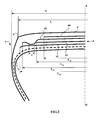
- the crown reinforcement is itself capped with a tread 6.
- the maximum axial width S of the tire is equal to 317 mm.
- the axial width L 41 of the first working layer 41 is equal to 252 mm.
- the axial width L 43 of the second working layer 43 is equal to 232 mm.
- the difference between the widths L 41 and L 43 is equal to 15 mm.
- the axial width L 42 of the layer of circumferential reinforcing elements 42 is equal to 194 mm.
- the last crown ply 44 has a width L 44 equal to 124 mm.
- the tensile modulus of elasticity at 10% elongation of the calendering layers of each of the working layers 41 and 43 is equal to 6 MPa.
- the tire 1 differs from that shown on the figure 1 in that the two working layers 41 and 43 are on each side of the equatorial plane and axially in the extension of the layer of reinforcing elements circumferences 42, coupled over an axial width 1: the cables of the first working layer 41 and the cables of the second working layer 43, over the axial coupling width 1 of the two layers, are separated radially from each other by a layer of gum, whose thickness is minimal and corresponds to twice the thickness of the rubbery calendering layer of 9.28 non-shrunk metal cables which is formed each working layer 41, 43, 0.8 mm. On the remaining width common to the two working layers, the two working layers 41, 43 are separated by a layer of rubber mix.
- Tests have been carried out with different tires made according to the invention in accordance with the representation of the figure 1 and compared with a tire a reference tire T1 having no layers of circumferential reinforcing elements, whose tensile elastic moduli at 10% elongation of the calenders of the working crown layers are greater than 8.5 MPa and whose values of tan ( ⁇ ) max of the calendars of the working crown layers are greater than 0.100.
- the calendars of the working layers consist of the mixture R1.
Description
La présente invention concerne un pneumatique, à armature de carcasse radiale et plus particulièrement un pneumatique destiné à équiper des véhicules portant de lourdes charges et roulant à vitesse soutenue, tels que, par exemple les camions, tracteurs, remorques ou bus routiers.The present invention relates to a tire, radial carcass reinforcement and more particularly a tire intended to equip vehicles carrying heavy loads and driving at a high speed, such as, for example, trucks, tractors, trailers or road buses.
D'une manière générale dans les pneumatiques de type poids-lourds, l'armature de carcasse est ancrée de part et d'autre dans la zone du bourrelet et est surmontée radialement par une armature de sommet constituée d'au moins deux couches, superposées et formées de fils ou câbles parallèles dans chaque couche et croisés d'une couche à la suivante en faisant avec la direction circonférentielle des angles compris entre 10° et 45°. Lesdites couches de travail, formant l'armature de travail, peuvent encore être recouvertes d'au moins une couche dite de protection et formée d'éléments de renforcement avantageusement métalliques et extensibles, dits élastiques. Elle peut également comprendre une couche de fils ou câbles métalliques à faible extensibilité faisant avec la direction circonférentielle un angle compris entre 45° et 90°, cette nappe, dite de triangulation, étant radialement située entre l'armature de carcasse et la première nappe de sommet dite de travail, formées de fils ou câbles parallèles présentant des angles au plus égaux à 45° en valeur absolue. La nappe de triangulation forme avec au moins ladite nappe de travail une armature triangulée, qui présente, sous les différentes contraintes qu'elle subit, peu de déformations, la nappe de triangulation ayant pour rôle essentiel de reprendre les efforts de compression transversale dont est l'objet l'ensemble des éléments de renforcement dans la zone du sommet du pneumatique.In general, in heavy-vehicle tires, the carcass reinforcement is anchored on both sides in the bead zone and is radially surmounted by a crown reinforcement consisting of at least two superposed layers. and formed of parallel wires or cables in each layer and crossed from one layer to the next by making with the circumferential direction angles between 10 ° and 45 °. Said working layers, forming the working armature, can still be covered with at least one so-called protective layer and formed of advantageously metallic and extensible reinforcing elements, called elastic elements. It may also comprise a layer of low extensibility wires or metal cables forming with the circumferential direction an angle of between 45 ° and 90 °, said triangulation ply being radially located between the carcass reinforcement and the first ply of plywood. so-called working top, formed of parallel wires or cables having angles at most equal to 45 ° in absolute value. The triangulation ply forms with at least said working ply a triangulated reinforcement, which presents, under the different stresses it undergoes, few deformations, the triangulation ply having the essential role of taking up the transverse compression forces of which the object all the reinforcing elements in the area of the crown of the tire.
Des câbles sont dits inextensibles lorsque lesdits câbles présentent sous une force de traction égale à 10% de la force de rupture un allongement relatif au plus égal à 0,2%.Cables are said to be inextensible when said cables have under tensile force equal to 10% of the breaking force a relative elongation of at most 0.2%.
Des câbles sont dits élastiques lorsque lesdits câbles présentent sous une force de traction égale à la charge de rupture un allongement relatif au moins égal à 3% avec un module tangent maximum inférieure à 150 GPa.Cables are said to be elastic when said cables have under a tensile force equal to the breaking load a relative elongation of at least 3% with a maximum tangent modulus of less than 150 GPa.
Des éléments de renforcement circonférentiels sont des éléments de renforcement qui font avec la direction circonférentielle des angles compris dans l'intervalle + 2,5°, - 2,5° autour de 0°.Circumferential reinforcing elements are reinforcing elements which make angles with the circumferential direction in the range + 2.5 °, - 2.5 ° around 0 °.
La direction circonférentielle du pneumatique, ou direction longitudinale, est la direction correspondant à la périphérie du pneumatique et définie par la direction de roulement du pneumatique.The circumferential direction of the tire, or longitudinal direction, is the direction corresponding to the periphery of the tire and defined by the rolling direction of the tire.
La direction transversale ou axiale du pneumatique est parallèle à l'axe de rotation du pneumatique.The transverse or axial direction of the tire is parallel to the axis of rotation of the tire.
La direction radiale est une direction coupant l'axe de rotation du pneumatique et perpendiculaire à celui-ci.The radial direction is a direction intersecting the axis of rotation of the tire and perpendicular to it.
L'axe de rotation du pneumatique est l'axe autour duquel il tourne en utilisation normale.The axis of rotation of the tire is the axis around which it rotates under normal use.
Un plan radial ou méridien est un plan qui contient l'axe de rotation du pneumatique.A radial or meridian plane is a plane which contains the axis of rotation of the tire.
Le plan médian circonférentiel, ou plan équatorial, est un plan perpendiculaire à l'axe de rotation du pneu et qui divise le pneumatique en deux moitiés.The circumferential median plane, or equatorial plane, is a plane perpendicular to the axis of rotation of the tire and which divides the tire into two halves.
On entend par « module d'élasticité » d'un mélange caoutchouteux, un module sécant d'extension à 10 % de déformation et à température ambiante.The term "modulus of elasticity" of a rubber mix, a secant modulus of extension at 10% deformation and at room temperature.
En ce qui concerne les compositions de caoutchouc, les mesures de module sont effectuées en traction selon la norme AFNOR-NFT-46002 de septembre 1988 : on mesure en seconde élongation (i.e., après un cycle d'accommodation) le module sécant nominal (ou contrainte apparente, en MPa) à 10% d'allongement (conditions normales de température et d'hygrométrie selon la norme AFNOR-NFT-40101 de décembre 1979).With regard to the rubber compositions, the modulus measurements are made in tension according to the AFNOR-NFT-46002 standard of September 1988: the second nominal elongation (ie, after an accommodation cycle) is measured by the nominal secant modulus (or apparent stress, in MPa) at 10% elongation (normal conditions of temperature and hygrometry according to the AFNOR-NFT-40101 standard of December 1979).
Certains pneumatiques actuels, dits "routiers", sont destinés à rouler à grande vitesse et sur des trajets de plus en plus longs, du fait de l'amélioration du réseau routier et de la croissance du réseau autoroutier dans le monde. L'ensemble des conditions, sous lesquelles un tel pneumatique est appelé à rouler, permet sans aucun doute un accroissement du nombre de kilomètres parcourus, l'usure du pneumatique étant moindre ; par contre l'endurance de ce dernier et en particulier de l'armature de sommet est pénalisée.Some current tires, called "road", are intended to run at high speed and on longer and longer journeys, because of the improvement of the road network and the growth of the motorway network in the world. The set of conditions under which such a tire is called to roll, undoubtedly allows an increase in the number of kilometers traveled, the wear of the tire being less; against the endurance of the latter and in particular of the crown reinforcement is penalized.
Il existe en effet des contraintes au niveau de l'armature de sommet et plus particulièrement des contraintes de cisaillement entre les couches de sommet, alliées à une élévation non négligeable de la température de fonctionnement au niveau des extrémités de la couche de sommet axialement la plus courte, qui ont pour conséquence l'apparition et la propagation de fissures de la gomme au niveau desdites extrémités.There are indeed constraints at the level of the crown reinforcement and more particularly shear stresses between the crown layers, combined with a not insignificant increase in the operating temperature at the ends of the axially most vertically facing crown layer. short, which result in the appearance and propagation of cracks of the rubber at said ends.
Afin d'améliorer l'endurance de l'armature de sommet du type de pneumatique étudié, des solutions relatives à la structure et qualité des couches et/ou profilés de mélanges caoutchouteux qui sont disposés entre et/ou autour des extrémités de nappes et plus particulièrement des extrémités de la nappe axialement la plus courte ont déjà été apportées.In order to improve the endurance of the crown reinforcement of the tire type studied, solutions relating to the structure and quality of the layers and / or profiles of rubber compounds which are arranged between and / or around the ends of the plies and more particularly ends of the axially shorter web have already been made.
Il est notamment connu d'introduire une couche de mélange caoutchouteux entre les extrémités des couches de travail pour créer un découplage entre lesdites extrémités pour limiter les contraintes e cisaillement. De telles couches de découplage doivent toutefois présenter une très bonne cohésion. De telles couches de mélanges caoutchouteux sont par exemple décrites dans la demande de brevet
Le brevet
Le brevet
Les pneumatiques ainsi réalisés permettent effectivement d'améliorer les performances notamment en termes d'endurance.The tires thus produced effectively improve performance, particularly in terms of endurance.
Par ailleurs, il est connu pour réaliser des pneumatiques à bande de roulement très large ou bien pour conférer à des pneumatiques d'une dimension donnée des capacités de charges plus importantes d'introduire une couche d'éléments de renforcement circonférentiels. La demande de brevet
Le document
Le document
La couche d'éléments de renforcement circonférentiels est usuellement constituées par au moins un câble métallique enroulé pour former une spire dont l'angle de pose par rapport à la direction circonférentielle est inférieur à 2.5°.The layer of circumferential reinforcing elements is usually constituted by at least one wire rope wound to form a turn whose laying angle relative to the circumferential direction is less than 2.5 °.
Un but de l'invention est de fournir des pneumatiques dont les propriétés notamment d'endurance et d'usure sont conservées quels que soient l'usage et dont les performances en termes de résistance au roulement sont améliorées pour contribuer à une moindre consommation de carburant par les véhicules équipés de tels pneumatiques.An object of the invention is to provide tires whose properties including endurance and wear are retained regardless of the use and whose performance in terms of rolling resistance are improved to contribute to lower fuel consumption by vehicles equipped with such tires.
Ce but est atteint selon l'invention par un pneumatique armature de carcasse radiale comprenant une armature de sommet formée d'au moins deux couches de sommet de travail chacune formée d'éléments de renforcement insérés entre deux couches de calandrage de mélange caoutchouteux, croisés d'une couche à l'autre en faisant avec la direction circonférentielle des angles compris entre 10° et 45°, l'armature de sommet étant coiffée radialement d'une bande de roulement, ladite bande de roulement étant réunie à deux bourrelets par l'intermédiaire de deux flancs, l'armature de sommet comportant au moins une couche d'éléments de renforcement circonférentiels, le module d'élasticité sous tension à 10 % d'allongement d'au moins une couche de calandrage d'au moins une couche de sommet de travail étant inférieur à 8,5 MPa, la valeur maximale de tan(δ), noté tan(δ)max, dudit calandrage étant inférieure à 0.100 et ladite au moins une couche de calandrage d'au moins une couche de sommet de travail étant un mélange élastomérique à base de caoutchouc naturel ou de polyisoprène synthétique à majorité d'enchaînements cis-1,4 et éventuellement d'au moins un autre élastomère diénique, le caoutchouc naturel ou le polyisoprène synthétique en cas de coupage étant présent à un taux majoritaire par rapport au taux de l'autre ou des autres élastomères diéniques utilisés et d'une charge renforçante constituée :
- a) soit par du noir de carbone de surface spécifique BET supérieure à 60 m2/g,
- i. employé à un taux compris entre 20 et 40 pce lorsque l'indice de structure du noir (COAN) est supérieur à 85,
- ii. employé à un taux compris entre 20 et 50 pce lorsque l'indice de structure du noir (COAN) est inférieur à 85,
- b) soit par du noir de carbone de surface spécifique BET inférieure à 60 m2/g, quelle que soit son indice de structure, employé à un taux compris entre 20 et 80 pce, et de préférence entre 30 et 50 pce,
- c) soit par une charge blanche de type silice et/ou alumine comportant des fonctions de surface SiOH et/ou AlOH choisie dans le groupe formé par les silices précipitées ou pyrogénées, les alumines ou les aluminosilicates ou bien encore les noirs de carbone modifiés en cours ou après la synthèse de surface spécifique BET comprise entre 130 et 260 m2/g, et de préférence supérieure à 150 m2/g, employée à un taux compris entre 20 et 80 pce, et de préférence entre 30 et 50 pce,
- d) soit par un coupage de noir de carbone décrit en (a) et/ou de noir de carbone décrit en (b) et/ou une charge blanche décrite en (c), dans lequel le taux global de charge est compris entre 20 et 80 pce, et de préférence entre 40 et 60 pce.
- a) carbon black with a BET specific surface area greater than 60 m 2 / g,
- i. used at a rate of between 20 and 40 phr when the Black Structure Index (COAN) is greater than 85,
- ii. used at a rate of between 20 and 50 phr when the Black Structure Index (COAN) is less than 85,
- b) carbon black with a BET specific surface area of less than 60 m 2 / g, irrespective of its structural index, employed at a level of between 20 and 80 phr, and preferably between 30 and 50 phr,
- c) either with a white filler of silica and / or alumina type having SiOH and / or AlOH surface functional groups chosen from the group formed by precipitated or pyrogenic silicas, aluminas or aluminosilicates or else modified carbon blacks; during or after the BET surface area synthesis of between 130 and 260 m 2 / g, and preferably greater than 150 m 2 / g, employed at a level of between 20 and 80 phr, and preferably between 30 and 50 phr,
- d) either by a carbon black cutting described in (a) and / or carbon black described in (b) and / or a white charge described in (c), wherein the overall charge rate is between 20 and 80 phr, and preferably between 40 and 60 phr.
La mesure de surface spécifique BET est effectuée selon la méthode de BRUNAUER, EMMET et TELLER décrite dans "
L'indice de structure du noir COAN (Compressed Oil Absorption Number) est mesuré selon la norme ASTM D3493.The structure index of the COAN black (Compressed Oil Absorption Number) is measured according to the ASTM D3493 standard.
Le facteur de perte tan(δ) est une propriété dynamique de la couche de mélange caoutchouteux. Il est mesuré sur un viscoanalyseur (Metravib VA4000), selon la norme ASTM D 5992-96. On enregistre la réponse d'un échantillon de composition vulcanisée (éprouvette cylindrique de 4 mm d'épaisseur et de 400 mm2 de section), soumis à une sollicitation sinusoïdale en cisaillement simple alterné, à la fréquence de 10Hz, à une température de 100°C. On effectue un balayage en amplitude de déformation de 0,1 à 50% (cycle aller), puis de 50% à 1% (cycle retour). Pour le cycle retour, on indique la valeur maximale de tan(δ) observée, noté tan(δ)max.The loss factor tan (δ) is a dynamic property of the layer of rubber mix. It is measured on a viscoanalyzer (Metravib VA4000), according to ASTM D 5992-96. The response of a sample of vulcanized composition (cylindrical specimen 4 mm in thickness and 400 mm 2 in section), subjected to a sinusoidal stress in alternating simple shear, at the frequency of 10 Hz, at a temperature of 100, is recorded. ° C. A strain amplitude sweep of 0.1 to 50% (forward cycle) and then 50% to 1% (return cycle) are performed. For the return cycle, the maximum value of tan (δ) observed, denoted tan (δ) max, is indicated .
La résistance au roulement est la résistance qui apparaît lorsque le pneumatique roule. Elle est représentée par les pertes hystérétiques liées à la déformation du pneumatique durant une révolution. Les valeurs de fréquence liées à la révolution du pneumatique correspondent à des valeurs de tan(δ) mesurée entre 30 et 100°C. La valeur de tan(δ) à 100 °C correspond ainsi à un indicateur de la résistance au roulement du pneumatique en roulage.Rolling resistance is the resistance that occurs when the tire is rolling. It is represented by the hysteretic losses related to the deformation of the tire during a revolution. The frequency values related to the revolution of the tire correspond to values of tan (δ) measured between 30 and 100 ° C. The value of tan (δ) at 100 ° C thus corresponds to an indicator of the rolling resistance of the rolling tire.
Il est encore possible d'estimer la résistance au roulement par la mesure des pertes d'énergie par rebond des échantillons à énergie imposée à des températures de 60 °C et exprimées en pourcentage.It is still possible to estimate the rolling resistance by measuring rebound energy losses of energy samples imposed at temperatures of 60 ° C and expressed as a percentage.
Avantageusement selon l'invention, la perte à 60 °C, notée P60, de la couche de mélange caoutchouteux C est inférieure à 20 %.Advantageously according to the invention, the loss at 60 ° C, noted P60, of the layer of rubber mix C is less than 20%.
Selon un mode préféré de réalisation de l'invention, le module d'élasticité sous tension à 10 % d'allongement des couches de calandrage desdites au moins deux couches de sommet de travail est inférieur à 8,5 MPa et la valeur tan(δ)max des couches de calandrage desdites au moins deux couches de sommet de travail est inférieure à 0.100.According to a preferred embodiment of the invention, the tensile modulus of elasticity at 10% elongation of the calendering layers of said at least two working crown layers is less than 8.5 MPa and the value tan (δ max of the calendering layers of said at least two working crown layers is less than 0.100.
L'utilisation de tels mélanges dont les modules d'élasticité sont inférieurs à 8.5 MPa et dont la valeur tan(δ)max est inférieure à 0.100 va permettre d'améliorer les propriétés du pneumatique en matière de résistance au roulement en conservant des propriétés d'endurance satisfaisante.The use of such mixtures whose elastic modulus are less than 8.5 MPa and whose tan (δ) max value is less than 0.100 will make it possible to improve the properties of the tire in terms of rolling resistance while maintaining the properties of the tire. satisfactory endurance.
Dans le cas d'utilisation de charge claire ou charge blanche, il est nécessaire d'utiliser un agent de couplage et/ou de recouvrement choisi parmi les agents connus de l'homme de l'art. Comme exemples d'agents de couplage préférentiel, on peut citer les alcoxysilanes sulfurés du type polysulfure de bis-(3-trialcoxysilylpropyle), et parmi ceux-ci notamment le tétrasulfure de bis-(3-triéthoxysilylpropyle) commercialisé par la Société DEGUSSA sous les dénominations Si69 pour le produit liquide pur et X50S pour le produit solide (coupage 50/50 en poids avec du noir N330). Comme exemples d'agents de recouvrement on peut citer un alcool gras, un alkylalcoxysilane tel qu'un hexadécyltriméthoxy ou triéthoxysilane respectivement commercialisés par la Société DEGUSSA sous les dénominations Si116 et Si216, la diphénylguanidine, un polyéthylène glycol, une huile silicone éventuellement modifié au moyen des fonctions OH ou alcoxy. L'agent de recouvrement et/ou de couplage est utilisé dans un rapport pondéral par rapport à la charge ≥ à 1/100 et ≤ à 20/100, et préférentiellement compris entre 2/100 et 15/100 lorsque la charge claire représente la totalité de la charge renforçante et compris entre 1/100 et 20/100 lorsque la charge renforçante est constituée par un coupage de noir de carbone et de charge claire.In the case of use of clear charge or white charge, it is necessary to use a coupling agent and / or covering selected from agents known to those skilled in the art. Examples of preferential coupling agents that may be mentioned are sulphurised alkoxysilanes of the bis (3-trialkoxysilylpropyl) polysulfide type, and of these, in particular, bis (3-triethoxysilylpropyl) tetrasulfide marketed by DEGUSSA under the Si69 denominations for pure liquid product and X50S for solid product (50/50 by weight blend with N330 black). Examples of coating agents that may be mentioned include a fatty alcohol, an alkylalkoxysilane such as hexadecyltrimethoxy or triethoxysilane respectively marketed by the company Degussa under the names Si116 and Si216, diphenylguanidine, a polyethylene glycol, a silicone oil which may be modified using OH or alkoxy functions. The covering agent and / or coupling is used in a weight ratio relative to the load ≥ 1/100 and ≤ 20/100, and preferably between 2/100 and 15/100 when the clear charge represents the all of the reinforcing filler and between 1/100 and 20/100 when the reinforcing filler is constituted by a carbon black and clear charge cutting.
Comme autres exemples de charges renforçantes ayant la morphologie et les fonctions de surface SiOH et/ou AlOH des matières de type silice et/ou alumine précédemment décrites et pouvant être utilisées selon l'invention en remplacement partiel ou total de celles-ci, on peut citer les noirs de carbone modifiés soit au cours de la synthèse par addition à l'huile d'alimentation du four d'un composé du silicium et/ou d'aluminium soit après la synthèse en ajoutant, à une suspension aqueuse de noir de carbone dans une solution de silicate et/ou d'aluminate de sodium, un acide de façon à recouvrir au moins partiellement la surface du noir de carbone de fonctions SiOH et/ou AlOH. Comme exemples non limitatifs de ce type de charges carbonées avec en surface des fonctions SiOH et/ou AlOH, on peut citer les charges type CSDP décrites dans la Conférence N° 24 du Meeting ACS, Rubber Division, Anaheim, Californie, 6-9 mai 1997 ainsi que celles de la demande de brevet
Lorsqu'une charge claire est utilisée comme seule charge renforçante, les propriétés d'hystérèse et de cohésion sont obtenues en utilisant une silice précipitée ou pyrogénée, ou bien une alumine précipitée ou bien encore un aluminosilicate de surface spécifique BET comprise entre 30 et 260 m2/g. Comme exemples non limitatifs de ce type de charge, on peut citer les silices KS404 de la Société Akzo, Ultrasil VN2 ou VN3 et BV3370GR de la Société Degussa, Zeopol 8745 de la Société Huber, Zeosil 175MP ou Zeosil 1165MP de la société Rhodia, HI-SIL 2000 de la Société PPG etc...When a clear filler is used as the only reinforcing filler, the hysteresis and cohesion properties are obtained by using a precipitated or fumed silica, or a precipitated alumina or even a BET surface area aluminosilicate of between 30 and 260 m 2 / g. As non-limiting examples of this type of filler, mention may be made of silicas KS404 from Akzo, Ultrasil VN2 or VN3 and BV3370GR from Degussa, Zeopol 8745 from Huber, Zeosil 175MP or Zeosil 1165MP from Rhodia, HI -SIL 2000 of the PPG Company etc ...
Parmi les élastomères diéniques pouvant être utilisés en coupage avec le caoutchouc naturel ou un polyisoprène synthétique à majorité d'enchaînements cis-1,4, on peut citer un polybutadiène (BR) de préférence à majorité d'enchaînements cis-1,4, un copolymère styrène-butadiène (SBR) solution ou émulsion, un copolymère butadiène-isoprène (BIR) ou bien encore un terpolymère styrène-butadiène-isoprène (SBIR). Ces élastomères peuvent être des élastomères modifiés en cours de polymérisation ou après polymérisation au moyen d'agents de ramification comme un divinylbenzène ou d'agents d'étoilage tels que des carbonates, des halogénoétains, des halogénosiliciums ou bien encore au moyen d'agents de fonctionnalisation conduisant à un greffage sur la chaîne ou en bout de chaîne de fonctions oxygénées carbonyle, carboxyle ou bien d'une fonction amine comme par exemple par action de la diméthyl ou de la diéthylamino benzophénone. Dans le cas de coupages de caoutchouc naturel ou de polyisoprène synthétique à majorité d'enchaînements cis-1,4 avec un ou plusieurs des élastomères diéniques, mentionnés ci-dessus, le caoutchouc naturel ou le polyisoprène synthétique est utilisé de préférence à un taux majoritaire et plus préférentiellement à un taux supérieur à 70 pce.Among the diene elastomers that can be used in a blend with natural rubber or synthetic polyisoprene with a majority of cis-1,4 linkages, mention may be made of a polybutadiene (BR), preferably with a majority of cis-1,4 linkages, a styrene-butadiene copolymer (SBR) solution or emulsion, a butadiene-isoprene copolymer (BIR) or even a styrene-butadiene-isoprene terpolymer (SBIR). These elastomers may be modified elastomers during polymerization or after polymerization by means of branching agents such as divinylbenzene or starch agents such as carbonates, halogenotins, halosilicons or else by means of functionalization leading to grafting on the chain or at the end of the chain of oxygen functions carbonyl, carboxyl or an amine function such as for example by the action of dimethyl or diethylamino benzophenone. In the case of blends of natural rubber or synthetic polyisoprene with a majority of cis-1,4 linkages with one or more of the diene elastomers mentioned above, the natural rubber or the synthetic polyisoprene is preferably used at a majority rate. and more preferably at a rate greater than 70 phr.
Selon ce mode de réalisation préféré de l'invention, un module d'élasticité plus faible s'accompagne généralement d'un module visqueux G" plus faible, cette évolution s'avérant favorable à une réduction de la résistance au roulement du pneumatique.According to this preferred embodiment of the invention, a lower modulus of elasticity is generally accompanied by a lower viscous modulus G ", this development being favorable to a reduction in the rolling resistance of the tire.
Habituellement, les modules d'élasticité sous tension à 10 % d'allongement des calandrages des couches de sommet sont supérieurs à 8.5 MPa et le plus souvent supérieurs à 10 MPa. De tels modules d'élasticité sont notamment requis pour permettre de limiter les mises en compression des éléments de renforcement des couches de sommet de travail notamment lorsque le véhicule suit un parcours sinueux, lors de manoeuvres sur les parkings ou bien lors du passage de ronds-points. En effet, les cisaillements selon la direction axiale qui s'opèrent sur la bande de roulement dans la zone de la surface de contact avec le sol conduisent à la mise en compression des éléments de renforcement d'une couche de sommet de travail.Usually, the tensile modulus of elasticity at 10% elongation of the crown layer calendering is greater than 8.5 MPa and most often greater than 10 MPa. Such elasticity moduli are in particular required to limit the compression of the reinforcing elements of the working crown layers, especially when the vehicle follows a winding course, when maneuvering on the car parks or during the passage of roundabouts. Indeed, the shears in the axial direction that occur on the tread in the area of the ground contact surface lead to the compression of reinforcing elements of a working crown layer.
Les inventeurs ont su mettre en évidence que la couche d'élément de renforcement circonférentiels autorise des choix de modules d'élasticité des mélanges caoutchouteux des couches de calandrages des couches de sommet de travail plus faibles sans nuire aux propriétés d'endurance du pneumatique du fait des mises en compression des éléments de renforcement desdites couches de sommet de travail telles que décrites précédemment.The inventors have been able to demonstrate that the circumferential reinforcement element layer allows the choice of modulus of elasticity of the rubber mixes of the lower work crown layers of the caliper layers without affecting the endurance properties of the tire because of compressing the reinforcing elements of said working crown layers as described above.
Les inventeurs ont encore su mettre en évidence que la cohésion des couches de calandrages des couches de sommet de travail, lorsqu'elle présente un module d'élasticité sous tension à 10 % d'allongement inférieur à 8.5 MPa, reste satisfaisante.The inventors have also been able to demonstrate that the cohesion of the layers of calendering of the working crown layers, when it has a tensile modulus of elasticity at 10% elongation less than 8.5 MPa, remains satisfactory.
Au sens de l'invention, un mélange caoutchouteux cohésif est un mélange caoutchouteux notamment robuste à la fissuration. La cohésion d'un mélange est ainsi évaluée par un test de fissuration en fatigue réalisé sur une éprouvette « PS » (pure shear). Il consiste à déterminer, après entaillage de l'éprouvette, la vitesse de propagation de fissure « Vp » (nm/cycle) en fonction du taux de restitution d'énergie « E » (J/m2). Le domaine expérimental couvert par la mesure est compris dans la plage -20°C et +150°C en température, avec une atmosphère d'air ou d'azote. La sollicitation de l'éprouvette est un déplacement dynamique imposé d'amplitude comprise entre 0.1mm et 10mm sous forme de sollicitation de type impulsionnel (signal « haversine » tangent) avec un temps de repos égal à la durée de l'impulsion ; la fréquence du signal est de l'ordre de 10Hz en moyenne.For the purposes of the invention, a cohesive rubbery mixture is a rubber compound which is particularly resistant to cracking. The cohesion of a mixture is thus evaluated by a fatigue cracking test performed on a specimen "PS" (pure shear). It consists in determining, after notching the specimen, the crack propagation speed "Vp" (nm / cycle) as a function of the energy release rate "E" (J / m 2 ). The experimental area covered by the measurement is in the range -20 ° C and + 150 ° C in temperature, with an air or nitrogen atmosphere. The biasing of the specimen is a dynamic displacement imposed amplitude ranging between 0.1mm and 10mm in the form of impulse-type stress (tangential "haversine" signal) with a rest time equal to the duration of the pulse; the frequency of the signal is of the order of 10 Hz on average.
La mesure comprend 3 parties :
- Une accommodation de l'éprouvette « PS », de 1000 cycles à 27% de déformation.
- une caractérisation énergétique pour déterminer la loi « E » = f (déformation). Le taux de restitution d'énergie « E » est égal à W0*h0, avec W0 = énergie fournie au matériau par cycle et par unité de volume et h0 = hauteur initiale de l'éprouvette. L'exploitation des acquisitions « force / déplacement » donne ainsi la relation entre « E » et l'amplitude de la sollicitation.
- La mesure de fissuration, après entaillage de l'éprouvette « PS ». Les informations recueillies conduisent à déterminer la vitesse de propagation de la fissure « Vp » en fonction du niveau de sollicitation imposé « E ».
- An accommodation of the "PS" test tube, with 1000 cycles at 27% deformation.
- an energetic characterization to determine the law "E" = f (deformation). The energy restitution rate "E" is equal to W0 * h0, with W0 = energy supplied to material per cycle and per unit volume and h0 = initial height of the specimen. The exploitation of acquisitions "force / displacement" thus gives the relation between "E" and the amplitude of the solicitation.
- The measurement of cracking, after notching of the test piece "PS". The information collected leads to determining the propagation velocity of the crack "Vp" as a function of the imposed stress level "E".
Les inventeurs ont notamment mis en évidence que la présence d'au moins une couche d'éléments de renforcement circonférentiels contribue à une moindre évolution de la cohésion des couches de calandrages des couches de sommet de travail. En effet, les conceptions de pneumatiques plus usuelles comportant notamment des couches de calandrages des couches de sommet de travail avec des modules d'élasticité sous tension à 10 % d'allongement supérieurs à 8.5 MPa, conduisent à une évolution de la cohésion desdites couches de calandrages des couches de sommet de travail, celle-ci tendant à s'affaiblir. Les inventeurs constatent que la présence d'au moins une couche d'éléments de renforcement circonférentiels qui contribue à limiter les mises en compression des éléments de renforcement des couches de sommet de travail notamment lorsque le véhicule suit un parcours sinueux et en outre, limite les augmentations de température conduit à une faible évolution de la cohésion des couches de calandrages. Les inventeurs considèrent ainsi que la cohésion des couches de calandrages des couches de sommet de travail, plus faible que ce qui existe dans les conceptions de pneumatiques plus usuelles, est satisfaisante dans la conception du pneumatique selon l'invention.The inventors have in particular demonstrated that the presence of at least one layer of circumferential reinforcing elements contributes to a lesser evolution of the cohesion of the layers of calendering of the working crown layers. Indeed, the more usual tire designs comprising, in particular, layers of calendering of the working crown layers with tensile modulus of elasticity at 10% elongation greater than 8.5 MPa, lead to an evolution of the cohesion of said layers of the worktop layers, which tend to weaken. The inventors find that the presence of at least one layer of circumferential reinforcing elements which contributes to limiting the compression of the reinforcement elements of the working crown layers, especially when the vehicle follows a sinuous path and furthermore limits the Increases in temperature lead to a slight change in the cohesion of the layers of calendering. The inventors thus consider that the cohesion of the caliper layers of the working crown layers, which is lower than that which exists in the more usual tire designs, is satisfactory in the design of the tire according to the invention.
Les inventeurs ont également mis en évidence que la combinaison d'une couche d'éléments de renforcement circonférentiels et de modules d'élasticité sous tension à 10 % d'allongement des calandrages des couches de sommet inférieurs à 8,5 MPa permet de conserver un effet ply-steer satisfaisant.The inventors have also demonstrated that the combination of a layer of circumferential reinforcing elements and of tensile modulus of elasticity at 10% elongation of the crown layer calenders less than 8.5 MPa makes it possible to preserve a satisfactory ply-steer effect.
L'effet ply-steer correspond à l'apparition d'une poussée transversale à dérive nulle du fait de la structure du pneumatique et notamment de la présence de couches de sommet de travail d'éléments de renforcement formant un angle avec la direction circonférentiel compris entre 10 et 45° qui sont à l'origine de ladite poussée lors de leurs déformations du fait du passage dans l'aire de contact formée par l'écrasement du pneumatique sur le sol lorsque le pneumatique est en roulage.The ply-steer effect corresponds to the appearance of zero drift transverse thrust due to the structure of the tire and in particular the presence of working crown layers of reinforcement elements forming an angle with the circumferential direction included between 10 and 45 ° which are at the origin of the said thrust during their deformations due to the passage in the contact area formed by the crash of the tire on the ground when the tire is running.
Les inventeurs ont ainsi mis en évidence que l'effet ply-steer, qui est modifié du fait de la présence d'une couche d'éléments de renforcement circonférentiels, voit sa variation atténuée du fait du choix de mélanges de calandrages des couches de travail avec des modules d'élasticité réduits. En effet, la poussée transversale augmente du fait de la présence d'une couche d'éléments de renforcement circonférentiels par rapport à un même pneumatique sans ladite couche d'éléments de renforcement circonférentiels et cette augmentation est atténuée par un choix de mélanges de calandrages des couches de travail avec des modules d'élasticité réduits par rapport à ceux habituellement utilisés.The inventors have thus demonstrated that the ply-steer effect, which is modified by virtue of the presence of a layer of circumferential reinforcing elements, has its variation attenuated because of the choice of calendering mixes of the working layers. with reduced elasticity modules. Indeed, the transverse thrust increases because of the presence of a layer of circumferential reinforcing elements with respect to the same tire without said layer of circumferential reinforcing elements and this increase is attenuated by a choice of calendering mixtures of working layers with reduced modulus of elasticity compared to those usually used.
Selon un mode de réalisation avantageux de l'invention, lesdits éléments de renforcement d'au moins une couche de sommet de travail sont des câbles à couches saturées, au moins une couche interne étant gainée d'une couche constituée d'une composition polymérique telle qu'une composition de caoutchouc non réticulable, réticulable ou réticulée, de préférence à base d'au moins un élastomère diénique.According to an advantageous embodiment of the invention, said reinforcing elements of at least one working crown layer are saturated layer cables, at least one inner layer being sheathed with a layer consisting of a polymeric composition such as a non-crosslinkable, crosslinkable or crosslinked rubber composition, preferably based on at least one diene elastomer.
Des câbles dits "à couches" ("layered cords") ou "multicouches" sont des câbles constitués d'un noyau central et d'une ou plusieurs couches de brins ou fils pratiquement concentriques disposées autour de ce noyau central.So-called " layered cords " or "multilayer" cables are cables consisting of a central core and one or more layers of substantially concentric strands or wires arranged around this central core.
Au sens de l'invention, une couche saturée d'un câble à couches est une couche constituée de fils dans laquelle il n'existe pas suffisamment de place pour y ajouter au moins un fil supplémentaire.Within the meaning of the invention, a saturated layer of a layered cable is a layer consisting of wires in which there is not enough room to add at least one additional wire.
Les inventeurs ont su mettre en évidence que la présence des câbles tels qu'ils viennent d'être décrits comme éléments de renforcement des couches de sommet de travail permettent de contribuer à de meilleures performances en termes d'endurance.The inventors have demonstrated that the presence of the cables as just described as strengthening elements of the working crown layers can contribute to better performance in terms of endurance.
En effet, il apparaît comme expliqué ci-dessus que les mélanges caoutchouteux des calandrages des couches de travail permettent de diminuer la résistance au roulement du pneumatique. Cela se traduit par une baisse des températures de ces mélanges caoutchouteux, lors de l'utilisation du pneumatique, qui peut entraîner une moindre protection des éléments de renforcement vis-à-vis des phénomènes d'oxydation dans certains cas d'utilisation du pneumatique. En effet, les propriétés des mélanges caoutchouteux relatives au blocage de l'oxygène diminuent avec la température et la présence d'oxygène peut conduire à une dégénérescence progressive des propriétés mécaniques des câbles, pour les conditions de roulage les plus sévères, et peut altérer la durée de vie de ces câbles.In fact, it appears as explained above that the rubber mixes of the calenders of the working layers make it possible to reduce the rolling resistance of the tire. This results in lower temperatures of these rubber mixes, when using the tire, which may result in less protection of the reinforcing elements vis-à-vis the oxidation phenomena in certain cases of use of the tire. In fact, the properties of the rubber compounds relating to the oxygen blocking decrease with temperature and the presence of oxygen can lead to a gradual degeneration of the mechanical properties of the cables, for the most severe driving conditions, and can alter the lifetime of these cables.
La présence de la gaine de caoutchouc au sein des câbles décrits ci-dessus vient compenser cet éventuel risque d'oxydation des éléments de renforcement, la gaine contribuant au blocage de l'oxygène.The presence of the rubber sheath within the cables described above compensates for this possible risk of oxidation of the reinforcing elements, the sheath contributing to the blockage of oxygen.
Par l'expression "composition à base d'au moins un élastomère diénique", on entend de manière connue que la composition comprend à titre majoritaire (i.e. selon une fraction massique supérieure à 50%) ce ou ces élastomères diéniques.The term "composition based on at least one diene elastomer" is understood to mean in a known manner that the composition comprises in majority (i.e. in a mass fraction greater than 50%) this or these diene elastomers.
On notera que la gaine selon l'invention s'étend d'une manière continue autour de la couche qu'elle recouvre (c'est-à-dire que cette gaine est continue dans la direction "orthoradiale" du câble qui est perpendiculaire à son rayon), de manière à former un manchon continu de section transversale qui est avantageusement pratiquement circulaire.It will be noted that the sheath according to the invention extends in a continuous manner around the layer which it covers (that is to say that this sheath is continuous in the "orthoradial" direction of the cable which is perpendicular to its radius), so as to form a continuous sleeve of cross section which is preferably substantially circular.
On notera également que la composition de caoutchouc de cette gaine peut être réticulable ou réticulée, c'est-à-dire qu'elle comprend par définition un système de réticulation adapté pour permettre la réticulation de la composition lors de sa cuisson (i.e., son durcissement et non sa fusion) ; ainsi, cette composition de caoutchouc peut être qualifiée d'infusible, du fait qu'elle ne peut pas être fondue par chauffage à quelque température que ce soit.It will also be noted that the rubber composition of this sheath may be crosslinkable or crosslinked, that is to say that it comprises by definition a crosslinking system adapted to allow the crosslinking of the composition during its cooking (ie, its hardening and not melting); thus, this rubber composition can be described as infusible, since it can not be melted by heating at any temperature.
Par élastomère ou caoutchouc "diénique", on entend de manière connue un élastomère issu au moins en partie (i.e. un homopolymère ou un copolymère) de monomères diènes (monomères porteurs de deux doubles liaisons carbone-carbone, conjuguées ou non).By elastomer or "diene" rubber is meant in known manner an elastomer derived at least in part (i.e. a homopolymer or a copolymer) of monomers dienes (monomers bearing two carbon-carbon double bonds, conjugated or not).
De préférence, le système de réticulation de la gaine de caoutchouc est un système dit de vulcanisation, c'est-à-dire à base de soufre (ou d'un agent donneur de soufre) et d'un accélérateur primaire de vulcanisation. A ce système de vulcanisation de base peuvent s'ajouter divers accélérateurs secondaires ou activateurs de vulcanisation connus.Preferably, the system for crosslinking the rubber sheath is a so-called vulcanization system, that is to say based on sulfur (or a sulfur-donor agent) and a primary vulcanization accelerator. To this basic vulcanization system may be added various known secondary accelerators or vulcanization activators.
La composition de caoutchouc de la gaine selon l'invention peut comprendre, outre ledit système de réticulation, tous les ingrédients habituels utilisables dans les compositions de caoutchouc pour pneumatiques, tels que des charges renforçantes à base de noir de carbone et/ou d'une charge inorganique renforçante telle que silice, des agents anti-vieillissement, par exemple des antioxydants, des huiles d'extension, des plastifiants ou des agents facilitant la mise en oeuvre des compositions à l'état cru, des accepteurs et donneurs de méthylène, des résines, des bismaléimides, des systèmes promoteurs d'adhésion connus du type "RFS" (résorcinol-formaldéhyde-silice) ou sels métalliques, notamment des sels de cobalt.The rubber composition of the sheath according to the invention may comprise, in addition to said crosslinking system, all the usual ingredients which can be used in tire rubber compositions, such as reinforcing fillers based on carbon black and / or reinforcing inorganic filler such as silica, anti-aging agents, for example antioxidants, extender oils, plasticizers or agents facilitating the use of the compositions in the green state, acceptors and donors of methylene, resins, bismaleimides, known adhesion promoter systems of the "RFS" type (resorcinol-formaldehyde-silica) or metal salts, especially cobalt salts.
A titre préférentiel, la composition de cette gaine est choisie identique à la composition utilisée pour la couche de calandrage de la couche de sommet de travail que les câbles sont destinés à renforcer. Ainsi, il n'y a aucun problème d'incompatibilité éventuelle entre les matériaux respectifs de la gaine et de la matrice de caoutchouc.As a preference, the composition of this sheath is chosen to be identical to the composition used for the calender layer of the working crown layer that the cables are intended to reinforce. Thus, there is no problem of possible incompatibility between the respective materials of the sheath and the rubber matrix.
Selon une variante de l'invention, lesdits câbles d'au moins une couche de sommet de travail sont des câbles à couches de construction [L+M], comportant une première couche C1 à L fils de diamètre d1 enroulés ensemble en hélice selon un pas p1 avec L allant de 1 à 4, entourée d'au moins une couche intermédiaire C2 à M fils de diamètre d2 enroulés ensemble en hélice selon un pas p2 avec M allant de 3 à 12, une gaine constituée d'une composition de caoutchouc non réticulable, réticulable ou réticulée à base d'au moins un élastomère diénique, recouvrant, dans la construction ladite première couche C1.According to a variant of the invention, said cables of at least one working crown layer are cables with building layers [L + M], comprising a first layer C1 to L son of diameter d 1 wound together in a helix according to a pitch p 1 with L ranging from 1 to 4, surrounded by at least one intermediate layer C2 to M son of diameter d 2 wound together helically in a pitch p 2 with M ranging from 3 to 12, a sheath consisting of a non-crosslinkable, crosslinkable or crosslinked rubber composition based on at least one diene elastomer, covering, in the construction, said first layer C1.
De préférence, le diamètre des fils de la première couche de la couche interne (C1) est compris entre 0.10 et 0.5 mm et le diamètre des fils de la couche externe (C2) est compris entre 0.10 et 0.5 mm.Preferably, the diameter of the wires of the first layer of the inner layer (C1) is between 0.10 and 0.5 mm and the diameter of the wires of the outer layer (C2) is between 0.10 and 0.5 mm.
De préférence encore, le pas d'hélice d'enroulement desdits fils de la couche externe (C2) est compris entre 8 et 25 mm.More preferably, the pitch of the winding helix of said son of the outer layer (C2) is between 8 and 25 mm.
Au sens de l'invention, le pas d'hélice représente la longueur, mesurée parallèlement à l'axe du câble, au bout de laquelle un fil ayant ce pas effectue un tour complet autour de l'axe du câble ; ainsi, si l'on sectionne l'axe par deux plans perpendiculaires audit axe et séparés par une longueur égale au pas d'un fil d'une couche constitutive du câble, l'axe de ce fil a dans ces deux plans la même position sur les deux cercles correspondant à la couche du fil considéré.In the sense of the invention, the pitch of the helix represents the length, measured parallel to the axis of the cable, at the end of which a wire having this pitch performs a complete revolution around the axis of the cable; thus, if the axis is divided by two planes perpendicular to said axis and separated by a length equal to the pitch of a wire of a layer constitutive cable, the axis of this wire has in these two planes the same position on the two circles corresponding to the wire layer considered.
Avantageusement, le câble présente l'une, et plus préférentiellement encore l'ensemble des caractéristiques suivantes qui est vérifié(e) :
- la couche C2 est une couche saturée, c'est-à-dire qu'il n'existe pas suffisamment de place dans cette couche pour y ajouter au moins un (N+1)ème fil de diamètre d2, N représentant alors le nombre maximal de fils enroulables en une couche autour de la couche C1;
- la gaine de caoutchouc recouvre en outre la couche interne C1 et/ou sépare les fils deux à deux adjacents de la couche externe C2 ;
- la gaine de caoutchouc recouvre pratiquement la demi-circonférence radialement intérieure de chaque fil de la couche C2, de telle sorte qu'elle sépare les fils deux à deux adjacents de cette couche C2.
- the layer C2 is a saturated layer, that is to say that there is not enough space in this layer to add at least one (N + 1) th wire diameter d 2 , N then representing the maximum number of wires rollable in one layer around the layer C 1 ;
- the rubber sheath further covers the inner layer C1 and / or separates the adjacent two-to-two wires from the outer layer C2;
- the rubber sheath substantially covers the radially inner half-circumference of each wire of the layer C2, so that it separates the adjacent two-to-two wires of this layer C2.
De préférence, la gaine de caoutchouc présente une épaisseur moyenne allant de 0,010 mm à 0,040 mm.Preferably, the rubber sheath has an average thickness of 0.010 mm to 0.040 mm.
D'une manière générale, lesdits câbles selon l'invention peuvent être réalisés avec tout type de fils métalliques, notamment en acier, par exemple des fils en acier au carbone et/ou des fils en acier inoxydable. On utilise de préférence un acier au carbone, mais il est bien entendu possible d'utiliser d'autres aciers ou d'autres alliages.In general, said cables according to the invention can be made with any type of metal son, especially steel, for example carbon steel son and / or stainless steel son. Carbon steel is preferably used, but it is of course possible to use other steels or other alloys.
Lorsqu'un acier au carbone est utilisé, sa teneur en carbone (% en poids d'acier) est de préférence comprise entre 0,1% et 1,2%, plus préférentiellement de 0,4% à 1,0% ; ces teneurs représentent un bon compromis entre les propriétés mécaniques requises pour le pneumatique et la faisabilité du fil. Il est à noter qu'une teneur en carbone comprise entre 0,5% et 0,6% rend de tels aciers finalement moins coûteux car plus faciles à tréfiler. Un autre mode avantageux de réalisation de l'invention peut consister aussi, selon les applications visées, à utiliser des aciers à faible teneur en carbone, comprise par exemple entre 0,2% et 0,5%, en raison notamment d'un coût plus bas et d'une plus grande facilité de tréfilage.When a carbon steel is used, its carbon content (% by weight of steel) is preferably between 0.1% and 1.2%, more preferably from 0.4% to 1.0%; these grades represent a good compromise between the mechanical properties required for the tire and the feasibility of the wire. It should be noted that a carbon content of between 0.5% and 0.6% makes such steels ultimately less expensive because easier to draw. Another advantageous embodiment of the invention may also consist, depending on the applications concerned, of using steels with a low carbon content, for example between 0.2% and 0.5%, in particular because of a cost lower and easier to draw.
Lesdits câbles selon l'invention pourront être obtenus selon différentes techniques connues de l'homme du métier, par exemple en deux étapes, tout d'abord par gainage via une tête d'extrusion de l'âme ou couches C1, étape suivie dans un deuxième temps d'une opération finale de câblage ou retordage des M fils restants (couche C2) autour de la couche C1 ainsi gainée. Le problème de collant à l'état cru posé par la gaine de caoutchouc, lors des opérations intermédiaires éventuelles de bobinage et débobinage pourra être résolu de manière connue par l'homme du métier, par exemple par l'emploi d'un film intercalaire en matière plastique.Said cables according to the invention may be obtained according to various techniques known to those skilled in the art, for example in two steps, firstly by sheathing via an extrusion head of the core or layers C1, step followed in a second step of a final wiring operation or twisting the remaining M son (layer C2) around the layer C1 and sheathed. The problem of stickiness in the green state posed by the rubber sheath, during any intermediate operations of winding and uncoiling can be solved in a manner known to those skilled in the art, for example by the use of a spacer film. plastic material.
De tels câbles d'au moins une couche de sommet de travail sont par exemple choisis parmi les câbles décrits dans les demandes de brevet
Selon un mode de réalisation avantageux de l'invention, la couche de sommet de travail axialement la plus large est radialement à l'intérieur des autres couches de sommet de travail.According to an advantageous embodiment of the invention, the axially widest working crown layer is radially inside the other working crown layers.
Selon une variante avantageuse de réalisation de l'invention, la couche d'éléments de renforcement circonférentiels présente une largeur axiale supérieure à 0.5xS.According to an advantageous embodiment of the invention, the layer of circumferential reinforcing elements has an axial width greater than 0.5 × S.
S est la largeur maximale axiale du pneumatique, lorsque ce dernier est monté sur sa jante de service et gonflé à sa pression recommandée.S is the maximum axial width of the tire, when the latter is mounted on its service rim and inflated to its recommended pressure.
Les largeurs axiales des couches d'éléments de renforcement sont mesurées sur une coupe transversale d'un pneumatique, le pneumatique étant donc dans un état non gonflé.The axial widths of the reinforcing element layers are measured on a cross section of a tire, the tire therefore being in an uninflated state.
Selon une réalisation préférée de l'invention, au moins deux couches de sommet de travail présentent des largeurs axiales différentes, la différence entre la largeur axiale de la couche de sommet de travail axialement la plus large et la largeur axiale de la couche de sommet de travail axialement la moins large étant comprise entre 10 et 30 mm.According to a preferred embodiment of the invention, at least two working crown layers have different axial widths, the difference between the axial width of the axially widest working crown layer and the axial width of the vertex layer. axially the least wide working being between 10 and 30 mm.
Selon un mode de réalisation préférée de l'invention, la couche d'éléments de renforcement circonférentiels est radialement disposée entre deux couches de sommet de travail.According to a preferred embodiment of the invention, the layer of circumferential reinforcing elements is radially arranged between two working crown layers.
Selon ce mode de réalisation de l'invention, la couche d'éléments de renforcement circonférentiels permet de limiter de manière plus importante les mises en compression des éléments de renforcement de l'armature de carcasse qu'une couche semblable mise en place radialement à l'extérieur des couches de travail. Elle est préférablement radialement séparée de l'armature de carcasse par au moins une couche de travail de façon à limiter les sollicitations desdits éléments de renforcement et ne pas trop les fatiguer.According to this embodiment of the invention, the layer of circumferential reinforcing elements makes it possible to limit more significantly the compression of the reinforcement elements of the carcass reinforcement than a similar layer placed radially in place. outside working layers. It is preferably radially separated from the carcass reinforcement by at least one working layer so as to limit the stresses of said reinforcing elements and do not strain them too much.
Avantageusement encore selon l'invention, les largeurs axiales des couches de sommet de travail radialement adjacentes à la couche d'éléments de renforcement circonférentiels sont supérieures à la largeur axiale de ladite couche d'éléments de renforcement circonférentiels et de préférence, lesdites couches de sommet de travail adjacentes à la couche d'éléments de renforcement circonférentiels sont de part et d'autre du plan équatorial et dans le prolongement axial immédiat de la couche d'éléments de renforcement circonférentiels couplées sur une largeur axiale, pour être ensuite découplées par ladite couche C de mélange de caoutchouc au moins sur le restant de la largeur commune aux dites deux couches de travail.Advantageously again according to the invention, the axial widths of the working crown layers radially adjacent to the layer of circumferential reinforcing elements are greater than the axial width of said layer of circumferential reinforcing elements and preferably said top layers. adjacent to the layer of circumferential reinforcing elements are on either side of the equatorial plane and in the immediate axial extension of the layer of circumferential reinforcing elements coupled over an axial width, to be subsequently decoupled by said layer C of rubber mixture at least on the remainder of the width common to said two working layers.
La présence de tels couplages entre les couches de sommet de travail adjacentes à la couche d'éléments de renforcement circonférentiels permet la diminution des contraintes de tension agissant sur les éléments circonférentiels axialement le plus à l'extérieur et situé le plus près du couplage.The presence of such couplings between the working crown layers adjacent to the layer of circumferential reinforcing elements makes it possible to reduce the tension stresses acting on the axially outermost circumferential elements and located closest to the coupling.
Selon un mode de réalisation avantageux de l'invention, les éléments de renforcement d'au moins une couche d'éléments de renforcement circonférentiels sont des éléments de renforcement métalliques présentant un module sécant à 0,7 % d'allongement compris entre 10 et 120 GPa et un module tangent maximum inférieur à 150 GPa.According to an advantageous embodiment of the invention, the reinforcing elements of at least one layer of circumferential reinforcing elements are metal reinforcing elements having a secant modulus at 0.7% elongation between 10 and 120 GPa and a maximum tangent modulus less than 150 GPa.
Selon une réalisation préférée, le module sécant des éléments de renforcement à 0,7 % d'allongement est inférieur à 100 GPa et supérieur à 20 GPa, de préférence compris entre 30 et 90 GPa et de préférence encore inférieur à 80 GPa.According to a preferred embodiment, the secant modulus of the reinforcing elements at 0.7% elongation is less than 100 GPa and greater than 20 GPa, preferably between 30 and 90 GPa and more preferably less than 80 GPa.
De préférence également, le module tangent maximum des éléments de renforcement est inférieur à 130 GPa et de préférence encore inférieur à 120 GPa.Also preferably, the maximum tangent modulus of the reinforcing elements is less than 130 GPa and more preferably less than 120 GPa.
Les modules exprimés ci-dessus sont mesurés sur une courbe contrainte de traction en fonction de l'allongement déterminée avec une précontrainte de 20 MPa ramenée à la section de métal de l'élément de renforcement, la contrainte de traction correspondant à une tension mesurée ramenée à la section de métal de l'élément de renforcement.The modules expressed above are measured on a tensile stress curve as a function of the elongation determined with a preload of 20 MPa brought back to the metal section of the reinforcement element, the tensile stress corresponding to a measured tension brought back to the metal section of the reinforcing element.
Les modules des mêmes éléments de renforcement peuvent être mesurés sur une courbe contrainte de traction en fonction de l'allongement déterminée avec une précontrainte de 10 MPa ramenée à la section globale de l'élément de renforcement, la contrainte de traction correspondant à une tension mesurée ramenée à la section globale de l'élément de renforcement. La section globale de l'élément de renforcement est la section d'un élément composite constitué de métal et de caoutchouc, ce dernier ayant notamment pénétré l'élément de renforcement pendant la phase de cuisson du pneumatique.The modules of the same reinforcing elements can be measured on a tensile stress curve as a function of the elongation determined with a preload of 10 MPa reduced to the overall section of the reinforcing element, the tensile stress corresponding to a measured tension. brought back to the overall section of the reinforcing element. The overall section of the reinforcing element is the section of a composite element made of metal and rubber, the latter having in particular penetrated the reinforcing element during the baking phase of the tire.
Selon cette formulation relative à la section globale de l'élément de renforcement, les éléments de renforcement des parties axialement extérieures et de la partie centrale d'au moins une couche d'éléments de renforcement circonférentiels sont des éléments de renforcement métalliques présentant un module sécant à 0,7 % d'allongement compris entre 5 et 60 GPa et un module tangent maximum inférieur à 75 GPa.According to this formulation relating to the overall section of the reinforcing element, the reinforcing elements of the axially outer portions and of the central portion of at least one layer of circumferential reinforcing elements are metal reinforcing elements having a secant modulus at 0.7% elongation between 5 and 60 GPa and a maximum tangent modulus less than 75 GPa.
Selon une réalisation préférée, le module sécant des éléments de renforcement à 0,7 % d'allongement est inférieur à 50 Gpa et supérieur à 10 GPa, de préférence compris entre 15 et 45 GPa et de préférence encore inférieure à 40 GPa.According to a preferred embodiment, the secant modulus of the reinforcing elements at 0.7% elongation is less than 50 Gpa and greater than 10 GPa, preferably between 15 and 45 GPa and more preferably less than 40 GPa.
De préférence également, le module tangent maximum des éléments de renforcement est inférieur à 65 GPa et de préférence encore inférieur à 60 GPa.Also preferably, the maximum tangent modulus of the reinforcing elements is less than 65 GPa and more preferably less than 60 GPa.
Selon un mode de réalisation préféré, les éléments de renforcements d'au moins une couche d'éléments de renforcement circonférentiels sont des éléments de renforcement métalliques présentant une courbe contrainte de traction en fonction de l'allongement relatif ayant des faibles pentes pour les faibles allongements et une pente sensiblement constante et forte pour les allongements supérieurs. De tels éléments de renforcement de la nappe additionnelle sont habituellement dénommés éléments "bi-module".According to a preferred embodiment, the reinforcing elements of at least one layer of circumferential reinforcing elements are metal reinforcing elements having a tensile stress curve as a function of the relative elongation having small slopes for the low elongations. and a substantially constant and strong slope for the higher elongations. Such reinforcing elements of the additional ply are usually referred to as "bi-module" elements.
Selon une réalisation préférée de l'invention, la pente sensiblement constante et forte apparaît à partir d'un allongement relatif compris entre 0,1% et 0,5%.According to a preferred embodiment of the invention, the substantially constant and strong slope appears from a relative elongation of between 0.1% and 0.5%.
Les différentes caractéristiques des éléments de renforcement énoncées ci-dessus sont mesurées sur des éléments de renforcement prélevés sur des pneumatiques.The different characteristics of the reinforcing elements mentioned above are measured on reinforcing elements taken from tires.
Des éléments de renforcement plus particulièrement adaptés à la réalisation d'au moins une couche d'éléments de renforcement circonférentiels selon l'invention sont par exemple des assemblages de formule 21.23, dont la construction est 3x(0.26+6x0.23) 4.4/6.6 SS ; ce câble à torons est constitué de 21 fils élémentaires de formule 3 x (1+6), avec 3 torons tordus ensembles chacun constitué de 7 fils, un fil formant une âme centrale de diamètre égal à 26/100 mm et 6 fils enroulés de diamètre égal à 23/100 mm. Un tel câble présente un module sécant à 0,7% égal à 45 GPa et un module tangent maximum égal à 98 GPa, mesurés sur une courbe contrainte de traction en fonction de l'allongement déterminée avec une précontrainte de 20 MPa ramenée à la section de métal de l'élément de renforcement, la contrainte de traction correspondant à une tension mesurée ramenée à la section de métal de l'élément de renforcement. Sur une courbe contrainte de traction en fonction de l'allongement déterminée avec une précontrainte de 10 MPa ramenée à la section globale de l'élément de renforcement, la contrainte de traction correspondant à une tension mesurée ramenée à la section globale de l'élément de renforcement, ce câble de formule 21.23 présente un module sécant à 0,7% égal à 23 GPa et un module tangent maximum égal à 49 GPa.Reinforcing elements that are more particularly suitable for producing at least one layer of circumferential reinforcing elements according to the invention are, for example, assemblies of formula 21.23, the construction of which is 3x (0.26 + 6x0.23) 4.4 / 6.6 SS; this strand cable consists of 21 elementary wires of formula 3 x (1 + 6), with 3 twisted strands each consisting of 7 wires, a wire forming a central core of diameter equal to 26/100 mm and 6 coiled wires of diameter equal to 23/100 mm. Such a cable has a secant module at 0.7% equal to 45 GPa and a maximum tangent modulus equal to 98 GPa, measured on a tensile stress curve as a function of the elongation determined with a preload of 20 MPa brought back to the section. of the reinforcing element, the tensile stress corresponding to a measured voltage brought back to the metal section of the reinforcing element. On a tensile stress curve as a function of the elongation determined with a preload of 10 MPa brought back to the overall section of the reinforcing element, the tensile stress corresponding to a measured tension brought back to the overall section of the element of reinforcement, this cable of formula 21.23 has a secant module at 0.7% equal to 23 GPa and a maximum tangent modulus equal to 49 GPa.
De la même façon, un autre exemple d'éléments de renforcement est un assemblage de formule 21.28, dont la construction est 3x(0.32+6x0.28) 6.2/9.3 SS. Ce câble présente un module sécant à 0,7% égal à 56 GPa et un module tangent maximum égal à 102 GPa, mesurés sur une courbe contrainte de traction en fonction de l'allongement déterminée avec une précontrainte de 20 MPa ramenée à la section de métal de l'élément de renforcement, la contrainte de traction correspondant à une tension mesurée ramenée à la section de métal de l'élément de renforcement. Sur une courbe contrainte de traction en fonction de l'allongement déterminée avec une précontrainte de 10 MPa ramenée à la section globale de l'élément de renforcement, la contrainte de traction correspondant à une tension mesurée ramenée à la section globale de l'élément de renforcement, ce câble de formule 21.28 présente un module sécant à 0,7% égal à 27 GPa et un module tangent maximum égal à 49 GPa.In the same way, another example of reinforcement elements is an assembly of formula 21.28, whose construction is 3x (0.32 + 6x0.28) 6.2 / 9.3 SS. This cable has a secant module at 0.7% equal to 56 GPa and a maximum tangent modulus equal to 102 GPa, measured on a tensile stress curve as a function of the elongation determined with a preload of 20 MPa brought to the cross section. metal of the reinforcing element, the tensile stress corresponding to a measured voltage brought back to the metal section of the reinforcing element. On a tensile stress curve as a function of the elongation determined with a preload of 10 MPa brought back to the overall section of the reinforcing element, the tensile stress corresponding to a measured tension brought back to the overall section of the element of reinforcement, this cable Formula 21.28 has a secant modulus at 0.7% equal to 27 GPa and a maximum tangent modulus equal to 49 GPa.
L'utilisation de tels éléments de renforcement dans au moins une couche d'éléments de renforcement circonférentiels permet notamment de conserver des rigidités de la couche satisfaisante y compris après les étapes de conformation et de cuisson dans des procédés de fabrication usuels.The use of such reinforcing elements in at least one layer of circumferential reinforcing elements makes it possible in particular to maintain satisfactory layer stiffnesses even after the conformation and baking steps in conventional manufacturing processes.
Selon un deuxième mode de réalisation de l'invention, les éléments de renforcement circonférentiels peuvent être formées d'éléments métalliques inextensibles et coupés de manière à former des tronçons de longueur très inférieure à la circonférence de la couche la moins longue, mais préférentiellement supérieure à 0,1 fois ladite circonférence, les coupures entre tronçons étant axialement décalées les unes par rapport aux autres. De préférence encore, le module d'élasticité à la traction par unité de largeur de la couche additionnelle est inférieur au module d'élasticité à la traction, mesuré dans les mêmes conditions, de la couche de sommet de travail la plus extensible. Un tel mode de réalisation permet de conférer, de manière simple, à la couche d'éléments de renforcement circonférentiels un module pouvant facilement être ajusté (par le choix des intervalles entre tronçons d'une même rangée), mais dans tous les cas plus faible que le module de la couche constituée des mêmes éléments métalliques mais continus, le module de la couche additionnelle étant mesuré sur une couche vulcanisée d'éléments coupés, prélevée sur le pneumatique.According to a second embodiment of the invention, the circumferential reinforcing elements may be formed of inextensible metal elements and cut so as to form sections of length much shorter than the circumference of the least long layer, but preferably greater than 0.1 times said circumference, the cuts between sections being axially offset with respect to each other. More preferably, the tensile modulus of elasticity per unit width of the additional layer is less than the tensile modulus of elasticity, measured under the same conditions, of the most extensible working crown layer. Such an embodiment makes it possible to confer, in a simple manner, on the layer of circumferential reinforcement elements a module which can easily be adjusted (by the choice of intervals between sections of the same row), but in all cases weaker. the module of the layer consisting of the same metallic elements but continuous, the module of the additional layer being measured on a vulcanized layer of cut elements, taken from the tire.
Selon un troisième mode de réalisation de l'invention, les éléments de renforcement circonférentiels sont des éléments métalliques ondulés, le rapport a/λ de l'amplitude d'ondulation sur la longueur d'onde étant au plus égale à 0,09. De préférence, le module d'élasticité à la traction par unité de largeur de la couche additionnelle est inférieur au module d'élasticité à la traction, mesuré dans les mêmes conditions, de la couche de sommet de travail la plus extensible.According to a third embodiment of the invention, the circumferential reinforcing elements are corrugated metal elements, the ratio a / λ of the amplitude of waviness at the wavelength being at most equal to 0.09. Preferably, the tensile modulus of elasticity per unit width of the additional layer is smaller than the tensile modulus of elasticity, measured under the same conditions, of the most extensible working crown layer.
Les éléments métalliques sont préférentiellement des câbles d'acier.The metal elements are preferably steel cables.
Selon un mode de réalisation préféré de l'invention, les éléments de renforcement des couches de sommet de travail sont des câbles métalliques inextensibles.According to a preferred embodiment of the invention, the reinforcement elements of the working crown layers are inextensible metal cables.
L'invention prévoit encore avantageusement pour diminuer les contraintes de tension agissant sur les éléments circonférentiels axialement le plus à l'extérieur que l'angle formé avec la direction circonférentielle par les éléments de renforcement des couches de sommet de travail est inférieur à 30° et de préférence inférieur à 25°.The invention further advantageously provides for decreasing the voltage stresses acting on the axially outermost circumferential members that the angle formed with the circumferential direction by the reinforcing elements of the working crown layers is less than 30 ° and preferably less than 25 °.
Selon une autre variante avantageuse de l'invention, les couches de sommet de travail comportent des éléments de renforcement, croisés d'une nappe à l'autre, faisant avec la direction circonférentielle des angles variables selon la direction axiale, lesdits angles étant supérieurs sur les bords axialement extérieurs des couches d'éléments de renforcement par rapport aux angles desdits éléments mesurés au niveau du plan médian circonférentiel. Une telle réalisation de l'invention permet d'augmenter la rigidité circonférentielle dans certaines zones et au contraire de la diminuer dans d'autres, notamment pour diminuer les mises en compression de l'armature de carcasse.According to another advantageous variant of the invention, the working crown layers comprise reinforcing elements, crossed from one ply to the other, making with the circumferential direction variable angles in the axial direction, said angles being greater on the axially outer edges of the reinforcing element layers with respect to the angles of said elements measured at the circumferential mid-plane. Such an embodiment of the invention makes it possible to increase the circumferential rigidity in certain zones and, conversely, to reduce it in others, in particular to reduce the compression of the carcass reinforcement.
Une réalisation préférée de l'invention prévoit encore que l'armature de sommet est complétée radialement à l'extérieur par au moins une couche supplémentaire, dite de protection, d'éléments de renforcement dits élastiques, orientés par rapport à la direction circonférentielle avec un angle compris entre 10° et 45° et de même sens que l'angle formé par les éléments inextensibles de la couche de travail qui lui est radialement adjacente.A preferred embodiment of the invention further provides that the crown reinforcement is completed radially on the outside by at least one additional protective layer of so-called elastic reinforcing elements oriented with respect to the circumferential direction with a angle between 10 ° and 45 ° and in the same direction as the angle formed by the inextensible elements of the working layer which is radially adjacent thereto.
La couche de protection peut avoir une largeur axiale inférieure à la largeur axiale de la couche de travail la moins large. Ladite couche de protection peut aussi avoir une largeur axiale supérieure à la largeur axiale de la couche de travail la moins large, telle qu'elle recouvre les bords de la couche de travail la moins large et, dans le cas de la couche radialement supérieure comme étant le moins large, telle qu'elle soit couplée, dans le prolongement axial de l'armature additionnelle, avec la couche de sommet de travail la plus large sur une largeur axiale, pour être ensuite, axialement à l'extérieur, découplée de ladite couche de travail la plus large par des profilés d'épaisseur au moins égale à 2 mm. La couche de protection formée d'éléments de renforcement élastiques peut, dans le cas cité ci-dessus, être d'une part éventuellement découplée des bords de ladite couche de travail la moins large par des profilés d'épaisseur sensiblement moindre que l'épaisseur des profilés séparant les bords des deux couches de travail, et avoir d'autre part une largeur axiale inférieure ou supérieure à la largeur axiale de la couche de sommet la plus large.The protective layer may have an axial width smaller than the axial width of the narrower working layer. Said protective layer may also have an axial width greater than the axial width of the narrower working layer, such that it covers the edges of the narrower working layer and, in the case of the radially upper layer, being the smallest, as coupled, in the axial extension of the additional reinforcement, with the widest working crown layer over an axial width, to be subsequently, axially outside, decoupled from said widest working layer with profiles at least 2 mm thick. The protective layer formed of elastic reinforcing elements may, in the case mentioned above, be on the one hand optionally decoupled from the edges of said least-extensive working layer by profiles of thickness substantially less than the thickness profiles separating the edges of the two working layers, and have on the other hand an axial width less than or greater than the axial width of the widest vertex layer.
Selon l'un quelconque des modes de réalisation de l'invention évoqué précédemment, l'armature de sommet peut encore être complétée, radialement à l'intérieur entre l'armature de carcasse et la couche de travail radialement intérieure la plus proche de ladite armature de carcasse, par une couche de triangulation d'éléments de renforcement inextensibles métalliques en acier faisant, avec la direction circonférentielle, un angle supérieur à 60° et de même sens que celui de l'angle formé par les éléments de renforcement de la couche radialement la plus proche de l'armature de carcasse.According to any one of the embodiments of the invention mentioned above, the crown reinforcement can be further completed, radially inwardly between the carcass reinforcement and the radially inner working layer closest to said reinforcement. of carcass, by a triangulation layer of steel metal non-extensible reinforcing elements forming, with the circumferential direction, an angle greater than 60 ° and in the same direction as that of the angle formed by the reinforcing elements of the layer radially. closest to the carcass reinforcement.
Le pneumatique selon l'invention tel qu'il vient d'être décrit présente donc une résistance au roulement améliorée par rapport aux pneumatiques usuels tout en conservant des performances en termes d'endurance et d'usure comparables.The tire according to the invention as just described thus has improved rolling resistance compared to conventional tires while maintaining comparable performance in terms of endurance and wear.
En outre, les modules d'élasticité plus faibles des mélanges caoutchouteux des calandrages des couches de sommet de travail permettent d'assouplir le sommet du pneumatique et ainsi limiter les risques d'agressions du sommet et de corrosion des éléments de renforcement des couches d'armature de sommet lorsque par exemple des cailloux sont retenus dans les fonds de sculpture.In addition, the lower elasticity moduli of the rubber mixes of the working crown layer calenders make it possible to soften the crown of the tire and thus limit the risks of crown damage and corrosion of the reinforcing elements of the layers of the tire. crown reinforcement when for example pebbles are retained in the sculpture grounds.
D'autres détails et caractéristiques avantageux de l'invention ressortiront ci-après de la description des exemples de réalisation de l'invention en référence aux
-
figure 1 , une vue méridienne d'un schéma d'un pneumatique selon un premier mode de réalisation de l'invention, -
figure 2 , une vue méridienne d'un schéma d'un pneumatique selon un deuxième mode de réalisation de l'invention.
-
figure 1 , a meridian view of a diagram of a tire according to a first embodiment of the invention, -
figure 2 , a meridian view of a diagram of a tire according to a second embodiment of the invention.
Les figures ne sont pas représentées à l'échelle pour en simplifier la compréhension. Les figures ne représentent qu'une demi-vue d'un pneumatique qui se prolonge de manière symétrique par rapport à l'axe XX' qui représente le plan médian circonférentiel, ou plan équatorial, d'un pneumatique.The figures are not shown in scale to simplify understanding. The figures represent only a half-view of a tire which extends symmetrically with respect to the axis XX 'which represents the circumferential median plane, or equatorial plane, of a tire.
Sur la
- d'une première couche de travail 41 formée de câbles métalliques inextensibles 9.28 non frettés, continus sur toute la largeur de la nappe, orientés d'un angle égal à 24°,
- d'une couche d'éléments de renforcement circonférentiels 42 formée de câbles métalliques en acier 21x23, de type "bi-module",
- d'une seconde couche de travail 43 formée de câbles métalliques inextensibles 9.28 non frettés, continus sur toute la largeur de la nappe, orientés d'un angle égal à 24° et croisés avec les câbles métalliques de la couche 41,
- d'une couche de
protection 44 formées de câbles métalliques élastiques 6.35.
- a
first working layer 41 formed of unstretchable, inextensible 9.28 metal cables, continuous over the entire width of the web, oriented at an angle equal to 24 °, - a layer of
circumferential reinforcing elements 42 formed of 21x23 steel cables of "bi-module" type, - a
second working layer 43 formed of inextensible metal cables 9.28 not shrunk, continuous over the entire width of the sheet, oriented at an angle of 24 ° and crossed with the metal cables of thelayer 41, - a
protective layer 44 formed of elastic metal cables 6.35.
L'armature de sommet est elle-même coiffée d'une bande de roulement 6.The crown reinforcement is itself capped with a
La largeur axiale maximale S du pneumatique est égale à 317 mm.The maximum axial width S of the tire is equal to 317 mm.
La largeur axiale L41 de la première couche de travail 41 est égale à 252 mm.The axial width L 41 of the
La largeur axiale L43 de la deuxième couche de travail 43 est égale à 232 mm. La différence entre les largeurs L41 et L43 est égale à 15 mm.The axial width L 43 of the
Quant à la largeur axiale L42 de la couche d'éléments de renforcement circonférentiels 42, elle est égale à 194 mm.As for the axial width L 42 of the layer of
La dernière nappe de sommet 44, dite de protection, a une largeur L44 égale à 124 mm.The
Conformément à l'invention, le module d'élasticité sous tension à 10 % d'allongement des couches de calandrage de chacune des couches de travail 41 et 43 est égal à 6 MPa.According to the invention, the tensile modulus of elasticity at 10% elongation of the calendering layers of each of the working
Sur la
Des essais ont été réalisés avec différents pneumatiques réalisés selon l'invention conformément à la représentation de la
Les différents mélanges utilisés sont listés ci-après, en exprimant pour chacun le module d'élasticité sous tension à 10 % d'allongement ainsi que les valeurs tan(δ)max et P60.
Les valeurs des constituants sont exprimées en pce (parties en poids pour cent parties d'élastomères.The values of the constituents are expressed in phr (parts by weight per hundred parts of elastomers.
Concernant le pneumatique de référence T1, les calandrages des couches de travail sont constitués du mélange R1.As regards the reference tire T1, the calendars of the working layers consist of the mixture R1.
Différents pneumatiques selon l'invention ont été testés, les calandrages des couches de travail étant constitués des mélanges 1 à 5.Different tires according to the invention have been tested, the calendering of the working layers consisting of
Des premiers essais d'endurance ont été réalisés sur une machine de test imposant à chacun des pneumatiques un roulage ligne droite à une vitesse égale à l'indice de vitesse maximum prescrit pour ledit pneumatique (speed index) sous une charge initiale de 4000 Kg progressivement augmentée pour réduire la durée du test.First endurance tests were carried out on a test machine requiring each tire to run a straight line at a speed equal to the maximum speed index prescribed for said tire (speed index) under an initial load of 4000 kg gradually. increased to reduce the duration of the test.
D'autres essais d'endurance ont été réalisés sur une machine de tests imposant de façon cyclique un effort transversal et une surcharge dynamique aux pneumatiques. Les essais ont été réalisés pour les pneumatiques selon l'invention avec des conditions identiques à celles appliquées aux pneumatiques de référence.Other endurance tests were carried out on a test machine imposing cyclically a transverse force and a dynamic overload to the tires. The tests were carried out for the tires according to the invention with conditions identical to those applied to the reference tires.
Les essais ainsi réalisés ont montré que les distances parcourues lors de chacun de ces tests sont sensiblement identiques pour les pneumatiques selon l'invention et les pneumatiques de référence. Il apparaît donc que les pneumatiques selon l'invention présentent des performances sensiblement équivalentes en termes d'endurance à celles des pneumatiques de référence.The tests thus carried out have shown that the distances traveled during each of these tests are substantially identical for the tires according to the invention and the reference tires. It therefore appears that the tires according to the invention have substantially equivalent performance in terms of endurance to those of the reference tires.
D'autres essais de roulage ont été effectués sur des sols non bitumés constitués de cailloux particulièrement agressifs pour les bandes de roulement des pneumatiques.Other rolling tests have been carried out on unpaved soils made of pebbles which are particularly aggressive for tire treads.
Ces derniers essais ont montré qu'après des distances parcourues identiques les pneumatiques selon l'invention présentent des altérations moins nombreuses et moins importantes que celles des pneumatiques de référence.These last tests have shown that after identical distances traveled the tires according to the invention have less numerous alterations and less important than those of the reference tires.
Ces essais montrent notamment que la conception des pneumatiques selon l'invention autorise une diminution du module d'élasticité des calandrages des couches de sommet de travail sans nuire aux performances d'endurance lorsqu'une couche d'éléments de renforcement circonférentiels est présente.These tests show in particular that the design of the tires according to the invention allows a reduction in the modulus of elasticity of the calenders of the working crown layers without affecting the endurance performance when a layer of circumferential reinforcing elements is present.
Par ailleurs, des mesures de résistance au roulement ont été effectuées. Ces mesures ont portés sur un premier pneumatique de référence T1 tel que décrit précédemment, sur un deuxième pneumatique de référence T2 identique au précédent et comportant en outre une couche d'éléments de renforcement circonférentiels identiques à celle des pneumatiques selon l'invention et sur un pneumatique I1 conforme à l'invention dont les couches de calandrage des couches de sommet de travail sont constituées du mélange 1.In addition, rolling resistance measurements have been made. These measurements relate to a first reference tire T1 as described above, on a second reference tire T2 identical to the previous one and further comprising a layer of circumferential reinforcement elements identical to that of the tires according to the invention and on a pneumatic I1 according to the invention, the calendering layers of the working crown layers consist of the
Les résultats des mesures sont présentés dans le tableau suivant ; elles sont exprimées en Kg/t, une valeur de 100 étant attribuée au pneumatique T1.
Claims (12)
- Tyre (1) having a radial carcass reinforcement (2) comprising a crown reinforcement (4) formed of at least two working crown layers (41, 43) each formed of reinforcing elements inserted between two calendering layers of rubber mixture, crossed from one layer to the other while forming, with the circumferential direction, angles of between 10° and 45°, the crown reinforcement being topped radially by a tread (5), the said tread being joined to two beads via two sidewalls, the crown reinforcement comprising at least one layer (42) of circumferential reinforcing elements, characterized in that the tensile modulus of elasticity at 10% elongation of at least one calendering layer of at least one working crown layer (41, 43) is less than 8.5 MPa and in that the maximum tan(δ) value, denoted tan(δ)max, measured at 100°C, of the said at least one calendering layer of at least one working crown layer is less than 0.100 and in that the said at least one calendering layer of at least one working crown layer (41, 43) is an elastomeric mixture based on natural rubber or on synthetic polyisoprene predominantly comprising cis-1,4 enchainments and optionally on at least one other diene elastomer, the natural rubber or the synthetic polyisoprene, in the case of a blend, being present at a predominant content with respect to the content of the other diene elastomer(s) used, and on a reinforcing filler consisting:a) either of carbon black with a BET specific surface of greater than 60 m2/g,i. employed at a content of between 20 and 40 phr when the structural index of the black (COAN) is greater than 85,ii. employed at a content of between 20 and 50 phr when the structural index of the black (COAN) is less than 85,b) or of carbon black with a BET specific surface of less than 60 m2/g, whatever its structural index, employed at a content of between 20 and 80 phr and preferably between 30 and 50 phr,c) or of a white filler of silica and/or alumina type comprising SiOH and/or AlOH surface functional groups, selected from the group consisting of precipitated or fumed silicas, aluminas and aluminosilicates, or alternatively carbon blacks modified during or after the synthesis having a BET specific surface of between 130 and 260 m2/g and preferably greater than 150m2/g, employed at a content of between 20 and 80 phr and preferably between 30 and 50 phr,d) or of a blend of carbon black described in (a) and/or of carbon black described in (b) and/or a white filler described in (c), in which the overall content of filler is between 20 and 80 phr and preferably between 40 and 60 phr.
- Tyre (1) according to Claim 1, characterized in that the said reinforcing elements of at least one working crown layer (41, 43) are saturated layered cords, at least one inner liner being sheathed with a layer consisting of a polymeric composition, such as a non-crosslinkable, crosslinkable or crosslinked rubber composition, preferably based on at least one diene elastomer.
- Tyre (1) according to either of Claims 1 and 2, characterized in that the layer (42) of circumferential reinforcing elements is positioned radially between two working crown layers (41,43).
- Tyre (1) according to one of the preceding claims, at least two working crown layers (41, 43) exhibiting different axial widths (L41, L43), characterized in that the difference between the axial width (L41) of the axially widest working crown layer (41) and the axial width (L43) of the axially narrowest working crown layer (43) is between 10 and 30 mm.
- Tyre (1) according to Claim 4, characterized in that the axially widest working crown layer (41) is radially interior to the other working crown layers.
- Tyre (1) according to one of the preceding claims, characterized in that the axial widths (L41, L43) of the working crown layers radially adjacent to the layer (42) of circumferential reinforcing elements are greater than the axial width (L42) of the said layer of circumferential reinforcing elements.
- Tyre (1) according to Claim 6, characterized in that the working crown layers (41, 43) adjacent to the layer (42) of circumferential reinforcing elements are on either side of the equatorial plane (X,X') and, in the immediate axial extension of the layer (42) of circumferential reinforcing elements, coupled over an axial width, in order to be subsequently decoupled by profiled elements of rubber mixture at least over the remainder of the width common to the said two working layers (41, 43).
- Tyre (1) according to one of the preceding claims, characterized in that the reinforcing elements of at least one layer (42) of circumferential reinforcing elements are metal reinforcing elements exhibiting a secant modulus at 0.7% elongation of between 10 and 120 GPa and a maximum tangent modulus of less than 150 GPa.
- Tyre (1) according to one of the preceding claims, characterized in that the reinforcing elements of the working crown layers (41, 43) are inextensible.
- Tyre (1) according to one of the preceding claims, characterized in that the angle formed by the reinforcing elements of the working crown layers (41, 43) with the circumferential direction is less than 30° and preferably less than 25°.
- Tyre (1) according to one of the preceding claims, characterized in that the crown reinforcement (4) is supplemented radially on the outside by at least one additional ply (44), known as protective ply, of "elastic" reinforcing elements, which are oriented, with respect to the circumferential direction, with an angle of between 10° and 45° and in the same direction as the angle formed by the inextensible elements of the working ply radially adjacent to it.
- Tyre (1) according to one of the preceding claims, characterized in that the crown reinforcement additionally comprises a triangulation layer formed of metal reinforcing elements forming, with the circumferential direction, angles greater than 60°.
Applications Claiming Priority (2)
| Application Number | Priority Date | Filing Date | Title |
|---|---|---|---|
| FR1159244A FR2981299B1 (en) | 2011-10-13 | 2011-10-13 | PNEUMATIC COMPRISING A LAYER OF CIRCUMFERENTIAL REINFORCING ELEMENTS |
| PCT/EP2012/070241 WO2013053880A1 (en) | 2011-10-13 | 2012-10-12 | Tyre comprising a layer of circumferential reinforcing elements |
Publications (2)
| Publication Number | Publication Date |
|---|---|
| EP2766202A1 EP2766202A1 (en) | 2014-08-20 |
| EP2766202B1 true EP2766202B1 (en) | 2015-12-30 |
Family
ID=47010607
Family Applications (1)
| Application Number | Title | Priority Date | Filing Date |
|---|---|---|---|
| EP12770495.5A Active EP2766202B1 (en) | 2011-10-13 | 2012-10-12 | Tyre comprising a layer of circumferential reinforcing elements |
Country Status (8)
| Country | Link |
|---|---|
| US (1) | US20140261951A1 (en) |
| EP (1) | EP2766202B1 (en) |
| JP (1) | JP6409214B2 (en) |
| CN (1) | CN103874587B (en) |
| BR (1) | BR112014008930B1 (en) |
| FR (1) | FR2981299B1 (en) |
| RU (1) | RU2014118763A (en) |
| WO (1) | WO2013053880A1 (en) |
Families Citing this family (17)
| Publication number | Priority date | Publication date | Assignee | Title |
|---|---|---|---|---|
| FR3038543B1 (en) * | 2015-07-06 | 2017-07-21 | Michelin & Cie | PNEUMATIC TYPE DEVICE FOR VEHICLE |
| FR3045483B1 (en) * | 2015-12-16 | 2017-12-22 | Michelin & Cie | PNEUMATIC HAVING IMPROVED WEAR AND ROLL RESISTANCE PROPERTIES |
| JP6648820B2 (en) * | 2016-04-08 | 2020-02-14 | 横浜ゴム株式会社 | Pneumatic tire |
| FR3051397B1 (en) * | 2016-05-20 | 2018-05-11 | Compagnie Generale Des Etablissements Michelin | PNEUMATIC HAVING PROTECTIVE LAYER WITH IMPROVED ENDURANCE PROPERTIES |
| FR3051398A1 (en) * | 2016-05-20 | 2017-11-24 | Michelin & Cie | PNEUMATIC HAVING PROTECTIVE LAYER WITH IMPROVED ENDURANCE PROPERTIES |
| KR102060640B1 (en) | 2016-09-09 | 2019-12-30 | 주식회사 엘지화학 | A reinforcing materials for rubber comprising aluminosilicate particles and rubber composition for tires comprising the same |
| FR3059598A1 (en) * | 2016-12-05 | 2018-06-08 | Compagnie Generale Des Etablissements Michelin | PNEUMATIC COMPRISING AN OVERLAPPED REINFORCEMENT FRAME |
| FR3059597A1 (en) * | 2016-12-05 | 2018-06-08 | Compagnie Generale Des Etablissements Michelin | PNEUMATIC COMPRISING AN OVERLAPPED REINFORCEMENT FRAME |
| FR3069190A1 (en) * | 2017-07-21 | 2019-01-25 | Compagnie Generale Des Etablissements Michelin | PNEUMATIC HAVING IMPROVED WEAR AND ROLL RESISTANCE PROPERTIES |
| JP6946875B2 (en) * | 2017-09-08 | 2021-10-13 | 住友ゴム工業株式会社 | Pneumatic tires |
| CN111315589B (en) * | 2017-11-08 | 2022-03-22 | 米其林集团总公司 | Pneumatic tire with lightweight crown reinforcement |
| EP3710283B1 (en) * | 2017-11-17 | 2021-07-28 | Compagnie Générale des Etablissements Michelin | Tyre comprising a carcass reinforcement layer having improved endurance properties |
| FR3079838B1 (en) * | 2018-04-09 | 2020-12-18 | Michelin & Cie | RUBBER COMPOSITION INCLUDING A REINFORCING LOAD WITH A LOW SPECIFIC SURFACE |
| FR3124113B1 (en) | 2021-06-17 | 2023-07-14 | Michelin & Cie | Method and device for heat treatment of a tire having improved rolling resistance properties |
| FR3134539A1 (en) * | 2022-04-14 | 2023-10-20 | Compagnie Generale Des Etablissements Michelin | Pneumatic with simplified crown reinforcement |
| FR3135918A1 (en) * | 2022-05-25 | 2023-12-01 | Compagnie Generale Des Etablissements Michelin | Pneumatic with a simplified aramid crown reinforcement |
| FR3137018A1 (en) * | 2022-06-28 | 2023-12-29 | Compagnie Generale Des Etablissements Michelin | Simplified pneumatics with a shrink-wrapped carcass reinforcement |
Family Cites Families (14)
| Publication number | Priority date | Publication date | Assignee | Title |
|---|---|---|---|---|
| US2643273A (en) * | 1950-03-18 | 1953-06-23 | Nat Standard Co | Method of securing rubber adhesion to metal and composition therefor |
| FR1389428A (en) | 1963-07-19 | 1965-02-19 | Pneumatiques, Caoutchouc Manufacture Et Plastiques Kleber Colombes | Heavy duty vehicle tire |
| DE2313586A1 (en) | 1973-03-19 | 1974-09-26 | Uniroyal Ag | VEHICLE AIR TIRES, IN PARTICULAR FOR TRUCKS |
| FR2729671B1 (en) * | 1995-01-20 | 1997-04-18 | Michelin & Cie | PRECIPITATED SILICA TIRE COVER WITH IMPROVED BEARING RESISTANCE |
| DE69626493T2 (en) | 1995-10-25 | 2003-11-20 | Yokohama Rubber Co Ltd | RUBBER COMPOSITION CONTAINING CARBON WHOSE SURFACE IS TREATED WITH SILICON DIOXIDE |
| FR2770458B1 (en) | 1997-11-05 | 1999-12-03 | Michelin & Cie | SUMMIT FRAME FOR TIRE-HEAVY TIRE |
| JP4861587B2 (en) * | 1999-12-30 | 2012-01-25 | ソシエテ ド テクノロジー ミシュラン | Tire rubber composition comprising a coupling agent (white filler / diene elastomer) activated by a heat-induced radical initiator |
| DE60128590T2 (en) * | 2001-01-02 | 2008-01-31 | Société de Technologie Michelin | RUBBER COMPOSITION BASED ON A DIENELASTOMER AND A REINFORCING SILICON CARBIDE |
| DE10213289A1 (en) * | 2001-03-30 | 2002-11-14 | Yokohama Rubber Co Ltd | Elastomer and steel cord composite and process for making the same |
| CN1750944B (en) | 2003-02-17 | 2011-08-17 | 米其林技术公司 | Crown reinforcement for radial tyre |
| FR2857620B1 (en) * | 2003-07-18 | 2005-08-19 | Michelin Soc Tech | PNEUMATIC FOR HEAVY VEHICLES |
| BRPI0412723B1 (en) * | 2003-07-18 | 2013-12-24 | Michelin Rech Tech | RADIAL HOUSING PNEUMATIC |
| FR2873721A1 (en) | 2004-08-02 | 2006-02-03 | Michelin Soc Tech | LAYERED CABLE FOR PNEUMATIC TOP REINFORCEMENT |
| FR2925922B1 (en) * | 2007-12-28 | 2009-12-18 | Soc Tech Michelin | LAYERED CABLE FOR PNEUMATIC BELT |
-
2011
- 2011-10-13 FR FR1159244A patent/FR2981299B1/en not_active Expired - Fee Related
-
2012
- 2012-10-12 RU RU2014118763/11A patent/RU2014118763A/en not_active Application Discontinuation
- 2012-10-12 WO PCT/EP2012/070241 patent/WO2013053880A1/en active Application Filing
- 2012-10-12 BR BR112014008930-2A patent/BR112014008930B1/en active IP Right Grant
- 2012-10-12 CN CN201280049984.1A patent/CN103874587B/en active Active
- 2012-10-12 EP EP12770495.5A patent/EP2766202B1/en active Active
- 2012-10-12 US US14/351,820 patent/US20140261951A1/en not_active Abandoned
- 2012-10-12 JP JP2014535100A patent/JP6409214B2/en not_active Expired - Fee Related
Also Published As
| Publication number | Publication date |
|---|---|
| BR112014008930B1 (en) | 2020-09-15 |
| CN103874587A (en) | 2014-06-18 |
| BR112014008930A8 (en) | 2017-12-26 |
| BR112014008930A2 (en) | 2017-04-25 |
| JP6409214B2 (en) | 2018-10-24 |
| WO2013053880A1 (en) | 2013-04-18 |
| EP2766202A1 (en) | 2014-08-20 |
| CN103874587B (en) | 2018-04-17 |
| JP2014534111A (en) | 2014-12-18 |
| RU2014118763A (en) | 2015-11-20 |
| US20140261951A1 (en) | 2014-09-18 |
| FR2981299A1 (en) | 2013-04-19 |
| FR2981299B1 (en) | 2014-07-11 |
Similar Documents
| Publication | Publication Date | Title |
|---|---|---|
| EP2766201B1 (en) | Tyre comprising a layer of circumferential reinforcing elements | |
| EP2766204B1 (en) | Tyre comprising a layer of circumferential reinforcing elements | |
| EP2766202B1 (en) | Tyre comprising a layer of circumferential reinforcing elements | |
| EP2788201B1 (en) | Tyre comprising a layer of circumferential reinforcing elements | |
| EP3160763B1 (en) | Tyre comprising a layer of circumferential reinforcing elements | |
| EP2788202B1 (en) | Tire comprising a circumferential reinforcing layer | |
| EP3160762B1 (en) | Tyre comprising a layer of circumferential reinforcing elements | |
| EP3297851B1 (en) | Tyre comprising working layers formed by individual wires | |
| EP3160766B1 (en) | Tyre comprising a layer of circumferential reinforcing elements | |
| EP3160761B1 (en) | Tyre comprising a layer of circumferential reinforcing elements | |
| EP3160765B1 (en) | Tyre comprising a layer of circumferential reinforcing elements | |
| EP3160770B1 (en) | Tyre comprising a layer of circumferential reinforcement elements | |
| EP3160768B1 (en) | Tyre comprising a layer of circumferential reinforcement elements | |
| EP3160764B1 (en) | Tyre comprising a layer of circumferential reinforcing elements | |
| EP3297852B1 (en) | Tyre comprising working layers formed by individual wires | |
| EP3390082A1 (en) | Tire having improved wear properties and improved rolling resistance | |
| WO2019197763A1 (en) | Light-weight tyre comprising a layer of circumferential reinforcing elements | |
| FR3089998A1 (en) | LIGHT TIRE COMPRISING A LAYER OF CIRCUMFERENTIAL REINFORCEMENT ELEMENTS |
Legal Events
| Date | Code | Title | Description |
|---|---|---|---|
| PUAI | Public reference made under article 153(3) epc to a published international application that has entered the european phase |
Free format text: ORIGINAL CODE: 0009012 |
|
| 17P | Request for examination filed |
Effective date: 20140513 |
|
| AK | Designated contracting states |
Kind code of ref document: A1 Designated state(s): AL AT BE BG CH CY CZ DE DK EE ES FI FR GB GR HR HU IE IS IT LI LT LU LV MC MK MT NL NO PL PT RO RS SE SI SK SM TR |
|
| DAX | Request for extension of the european patent (deleted) | ||
| GRAP | Despatch of communication of intention to grant a patent |
Free format text: ORIGINAL CODE: EPIDOSNIGR1 |
|
| INTG | Intention to grant announced |
Effective date: 20150918 |
|
| GRAS | Grant fee paid |
Free format text: ORIGINAL CODE: EPIDOSNIGR3 |
|
| GRAA | (expected) grant |
Free format text: ORIGINAL CODE: 0009210 |
|
| AK | Designated contracting states |
Kind code of ref document: B1 Designated state(s): AL AT BE BG CH CY CZ DE DK EE ES FI FR GB GR HR HU IE IS IT LI LT LU LV MC MK MT NL NO PL PT RO RS SE SI SK SM TR |
|
| REG | Reference to a national code |
Ref country code: GB Ref legal event code: FG4D Free format text: NOT ENGLISH |
|
| REG | Reference to a national code |
Ref country code: CH Ref legal event code: EP |
|
| REG | Reference to a national code |
Ref country code: AT Ref legal event code: REF Ref document number: 767283 Country of ref document: AT Kind code of ref document: T Effective date: 20160115 |
|
| REG | Reference to a national code |
Ref country code: IE Ref legal event code: FG4D Free format text: LANGUAGE OF EP DOCUMENT: FRENCH |
|
| REG | Reference to a national code |
Ref country code: DE Ref legal event code: R096 Ref document number: 602012013440 Country of ref document: DE |
|
| REG | Reference to a national code |
Ref country code: NL Ref legal event code: FP |
|
| REG | Reference to a national code |
Ref country code: LT Ref legal event code: MG4D |
|
| PG25 | Lapsed in a contracting state [announced via postgrant information from national office to epo] |
Ref country code: NO Free format text: LAPSE BECAUSE OF FAILURE TO SUBMIT A TRANSLATION OF THE DESCRIPTION OR TO PAY THE FEE WITHIN THE PRESCRIBED TIME-LIMIT Effective date: 20160330 Ref country code: HR Free format text: LAPSE BECAUSE OF FAILURE TO SUBMIT A TRANSLATION OF THE DESCRIPTION OR TO PAY THE FEE WITHIN THE PRESCRIBED TIME-LIMIT Effective date: 20151230 Ref country code: LT Free format text: LAPSE BECAUSE OF FAILURE TO SUBMIT A TRANSLATION OF THE DESCRIPTION OR TO PAY THE FEE WITHIN THE PRESCRIBED TIME-LIMIT Effective date: 20151230 |
|
| REG | Reference to a national code |
Ref country code: AT Ref legal event code: MK05 Ref document number: 767283 Country of ref document: AT Kind code of ref document: T Effective date: 20151230 |
|
| PG25 | Lapsed in a contracting state [announced via postgrant information from national office to epo] |
Ref country code: GR Free format text: LAPSE BECAUSE OF FAILURE TO SUBMIT A TRANSLATION OF THE DESCRIPTION OR TO PAY THE FEE WITHIN THE PRESCRIBED TIME-LIMIT Effective date: 20160331 Ref country code: SE Free format text: LAPSE BECAUSE OF FAILURE TO SUBMIT A TRANSLATION OF THE DESCRIPTION OR TO PAY THE FEE WITHIN THE PRESCRIBED TIME-LIMIT Effective date: 20151230 Ref country code: FI Free format text: LAPSE BECAUSE OF FAILURE TO SUBMIT A TRANSLATION OF THE DESCRIPTION OR TO PAY THE FEE WITHIN THE PRESCRIBED TIME-LIMIT Effective date: 20151230 Ref country code: LV Free format text: LAPSE BECAUSE OF FAILURE TO SUBMIT A TRANSLATION OF THE DESCRIPTION OR TO PAY THE FEE WITHIN THE PRESCRIBED TIME-LIMIT Effective date: 20151230 Ref country code: RS Free format text: LAPSE BECAUSE OF FAILURE TO SUBMIT A TRANSLATION OF THE DESCRIPTION OR TO PAY THE FEE WITHIN THE PRESCRIBED TIME-LIMIT Effective date: 20151230 |
|
| PG25 | Lapsed in a contracting state [announced via postgrant information from national office to epo] |
Ref country code: ES Free format text: LAPSE BECAUSE OF FAILURE TO SUBMIT A TRANSLATION OF THE DESCRIPTION OR TO PAY THE FEE WITHIN THE PRESCRIBED TIME-LIMIT Effective date: 20151230 Ref country code: IT Free format text: LAPSE BECAUSE OF FAILURE TO SUBMIT A TRANSLATION OF THE DESCRIPTION OR TO PAY THE FEE WITHIN THE PRESCRIBED TIME-LIMIT Effective date: 20151230 Ref country code: CZ Free format text: LAPSE BECAUSE OF FAILURE TO SUBMIT A TRANSLATION OF THE DESCRIPTION OR TO PAY THE FEE WITHIN THE PRESCRIBED TIME-LIMIT Effective date: 20151230 |
|
| PG25 | Lapsed in a contracting state [announced via postgrant information from national office to epo] |
Ref country code: PT Free format text: LAPSE BECAUSE OF FAILURE TO SUBMIT A TRANSLATION OF THE DESCRIPTION OR TO PAY THE FEE WITHIN THE PRESCRIBED TIME-LIMIT Effective date: 20160502 Ref country code: AT Free format text: LAPSE BECAUSE OF FAILURE TO SUBMIT A TRANSLATION OF THE DESCRIPTION OR TO PAY THE FEE WITHIN THE PRESCRIBED TIME-LIMIT Effective date: 20151230 Ref country code: EE Free format text: LAPSE BECAUSE OF FAILURE TO SUBMIT A TRANSLATION OF THE DESCRIPTION OR TO PAY THE FEE WITHIN THE PRESCRIBED TIME-LIMIT Effective date: 20151230 Ref country code: IS Free format text: LAPSE BECAUSE OF FAILURE TO SUBMIT A TRANSLATION OF THE DESCRIPTION OR TO PAY THE FEE WITHIN THE PRESCRIBED TIME-LIMIT Effective date: 20160430 Ref country code: RO Free format text: LAPSE BECAUSE OF FAILURE TO SUBMIT A TRANSLATION OF THE DESCRIPTION OR TO PAY THE FEE WITHIN THE PRESCRIBED TIME-LIMIT Effective date: 20151230 Ref country code: SM Free format text: LAPSE BECAUSE OF FAILURE TO SUBMIT A TRANSLATION OF THE DESCRIPTION OR TO PAY THE FEE WITHIN THE PRESCRIBED TIME-LIMIT Effective date: 20151230 Ref country code: PL Free format text: LAPSE BECAUSE OF FAILURE TO SUBMIT A TRANSLATION OF THE DESCRIPTION OR TO PAY THE FEE WITHIN THE PRESCRIBED TIME-LIMIT Effective date: 20151230 Ref country code: SK Free format text: LAPSE BECAUSE OF FAILURE TO SUBMIT A TRANSLATION OF THE DESCRIPTION OR TO PAY THE FEE WITHIN THE PRESCRIBED TIME-LIMIT Effective date: 20151230 |
|
| REG | Reference to a national code |
Ref country code: DE Ref legal event code: R097 Ref document number: 602012013440 Country of ref document: DE |
|
| REG | Reference to a national code |
Ref country code: FR Ref legal event code: PLFP Year of fee payment: 5 |
|
| PG25 | Lapsed in a contracting state [announced via postgrant information from national office to epo] |
Ref country code: DK Free format text: LAPSE BECAUSE OF FAILURE TO SUBMIT A TRANSLATION OF THE DESCRIPTION OR TO PAY THE FEE WITHIN THE PRESCRIBED TIME-LIMIT Effective date: 20151230 |
|
| PLBE | No opposition filed within time limit |
Free format text: ORIGINAL CODE: 0009261 |
|
| STAA | Information on the status of an ep patent application or granted ep patent |
Free format text: STATUS: NO OPPOSITION FILED WITHIN TIME LIMIT |
|
| 26N | No opposition filed |
Effective date: 20161003 |
|
| PG25 | Lapsed in a contracting state [announced via postgrant information from national office to epo] |
Ref country code: SI Free format text: LAPSE BECAUSE OF FAILURE TO SUBMIT A TRANSLATION OF THE DESCRIPTION OR TO PAY THE FEE WITHIN THE PRESCRIBED TIME-LIMIT Effective date: 20151230 Ref country code: BE Free format text: LAPSE BECAUSE OF NON-PAYMENT OF DUE FEES Effective date: 20161031 |
|
| REG | Reference to a national code |
Ref country code: CH Ref legal event code: PL |
|
| GBPC | Gb: european patent ceased through non-payment of renewal fee |
Effective date: 20161012 |
|
| REG | Reference to a national code |
Ref country code: IE Ref legal event code: MM4A |
|
| PG25 | Lapsed in a contracting state [announced via postgrant information from national office to epo] |
Ref country code: CH Free format text: LAPSE BECAUSE OF NON-PAYMENT OF DUE FEES Effective date: 20161031 Ref country code: GB Free format text: LAPSE BECAUSE OF NON-PAYMENT OF DUE FEES Effective date: 20161012 Ref country code: LI Free format text: LAPSE BECAUSE OF NON-PAYMENT OF DUE FEES Effective date: 20161031 |
|
| PG25 | Lapsed in a contracting state [announced via postgrant information from national office to epo] |
Ref country code: LU Free format text: LAPSE BECAUSE OF NON-PAYMENT OF DUE FEES Effective date: 20161012 |
|
| REG | Reference to a national code |
Ref country code: FR Ref legal event code: PLFP Year of fee payment: 6 |
|
| PG25 | Lapsed in a contracting state [announced via postgrant information from national office to epo] |
Ref country code: IE Free format text: LAPSE BECAUSE OF NON-PAYMENT OF DUE FEES Effective date: 20161012 |
|
| REG | Reference to a national code |
Ref country code: BE Ref legal event code: MM Effective date: 20161031 |
|
| PG25 | Lapsed in a contracting state [announced via postgrant information from national office to epo] |
Ref country code: HU Free format text: LAPSE BECAUSE OF FAILURE TO SUBMIT A TRANSLATION OF THE DESCRIPTION OR TO PAY THE FEE WITHIN THE PRESCRIBED TIME-LIMIT; INVALID AB INITIO Effective date: 20121012 |
|
| PG25 | Lapsed in a contracting state [announced via postgrant information from national office to epo] |
Ref country code: CY Free format text: LAPSE BECAUSE OF FAILURE TO SUBMIT A TRANSLATION OF THE DESCRIPTION OR TO PAY THE FEE WITHIN THE PRESCRIBED TIME-LIMIT Effective date: 20151230 Ref country code: MC Free format text: LAPSE BECAUSE OF FAILURE TO SUBMIT A TRANSLATION OF THE DESCRIPTION OR TO PAY THE FEE WITHIN THE PRESCRIBED TIME-LIMIT Effective date: 20151230 Ref country code: MT Free format text: LAPSE BECAUSE OF FAILURE TO SUBMIT A TRANSLATION OF THE DESCRIPTION OR TO PAY THE FEE WITHIN THE PRESCRIBED TIME-LIMIT Effective date: 20151230 Ref country code: MK Free format text: LAPSE BECAUSE OF FAILURE TO SUBMIT A TRANSLATION OF THE DESCRIPTION OR TO PAY THE FEE WITHIN THE PRESCRIBED TIME-LIMIT Effective date: 20151230 |
|
| PG25 | Lapsed in a contracting state [announced via postgrant information from national office to epo] |
Ref country code: BG Free format text: LAPSE BECAUSE OF FAILURE TO SUBMIT A TRANSLATION OF THE DESCRIPTION OR TO PAY THE FEE WITHIN THE PRESCRIBED TIME-LIMIT Effective date: 20151230 |
|
| REG | Reference to a national code |
Ref country code: FR Ref legal event code: PLFP Year of fee payment: 7 |
|
| PG25 | Lapsed in a contracting state [announced via postgrant information from national office to epo] |
Ref country code: TR Free format text: LAPSE BECAUSE OF FAILURE TO SUBMIT A TRANSLATION OF THE DESCRIPTION OR TO PAY THE FEE WITHIN THE PRESCRIBED TIME-LIMIT Effective date: 20151230 Ref country code: AL Free format text: LAPSE BECAUSE OF FAILURE TO SUBMIT A TRANSLATION OF THE DESCRIPTION OR TO PAY THE FEE WITHIN THE PRESCRIBED TIME-LIMIT Effective date: 20151230 |
|
| PGFP | Annual fee paid to national office [announced via postgrant information from national office to epo] |
Ref country code: NL Payment date: 20191021 Year of fee payment: 8 |
|
| REG | Reference to a national code |
Ref country code: NL Ref legal event code: MM Effective date: 20201101 |
|
| PG25 | Lapsed in a contracting state [announced via postgrant information from national office to epo] |
Ref country code: NL Free format text: LAPSE BECAUSE OF NON-PAYMENT OF DUE FEES Effective date: 20201101 |
|
| REG | Reference to a national code |
Ref country code: DE Ref legal event code: R081 Ref document number: 602012013440 Country of ref document: DE Owner name: COMPAGNIE GENERALE DES ETABLISSEMENTS MICHELIN, FR Free format text: FORMER OWNERS: COMPAGNIE GENERALE DES ETABLISSEMENTS MICHELIN, CLERMONT-FERRAND, FR; MICHELIN RECHERCHE ET TECHNIQUE S.A., GRANGES-PACCOT, CH |
|
| PGFP | Annual fee paid to national office [announced via postgrant information from national office to epo] |
Ref country code: FR Payment date: 20231025 Year of fee payment: 12 Ref country code: DE Payment date: 20231020 Year of fee payment: 12 |