EP2766064B1 - Selektiv bewegliche ventilelemente für absaug- und bewässerungszyklen - Google Patents
Selektiv bewegliche ventilelemente für absaug- und bewässerungszyklen Download PDFInfo
- Publication number
- EP2766064B1 EP2766064B1 EP12855496.1A EP12855496A EP2766064B1 EP 2766064 B1 EP2766064 B1 EP 2766064B1 EP 12855496 A EP12855496 A EP 12855496A EP 2766064 B1 EP2766064 B1 EP 2766064B1
- Authority
- EP
- European Patent Office
- Prior art keywords
- aspiration
- line
- irrigation
- vent
- selectively
- Prior art date
- Legal status (The legal status is an assumption and is not a legal conclusion. Google has not performed a legal analysis and makes no representation as to the accuracy of the status listed.)
- Active
Links
- 230000002262 irrigation Effects 0.000 title claims description 255
- 238000003973 irrigation Methods 0.000 title claims description 255
- 238000004891 communication Methods 0.000 claims description 40
- 239000012530 fluid Substances 0.000 claims description 40
- 239000002699 waste material Substances 0.000 claims description 7
- 230000008859 change Effects 0.000 claims description 4
- FAPWRFPIFSIZLT-UHFFFAOYSA-M Sodium chloride Chemical compound [Na+].[Cl-] FAPWRFPIFSIZLT-UHFFFAOYSA-M 0.000 claims description 3
- 239000011780 sodium chloride Substances 0.000 claims description 3
- 230000004044 response Effects 0.000 claims description 2
- 238000006073 displacement reaction Methods 0.000 description 16
- 238000010586 diagram Methods 0.000 description 13
- 238000000034 method Methods 0.000 description 13
- 238000001802 infusion Methods 0.000 description 9
- 230000002572 peristaltic effect Effects 0.000 description 7
- 238000005086 pumping Methods 0.000 description 7
- 238000001356 surgical procedure Methods 0.000 description 7
- 238000013022 venting Methods 0.000 description 6
- 239000003570 air Substances 0.000 description 5
- 208000002177 Cataract Diseases 0.000 description 4
- 230000009471 action Effects 0.000 description 4
- 239000013078 crystal Substances 0.000 description 4
- 210000004087 cornea Anatomy 0.000 description 3
- 229920001971 elastomer Polymers 0.000 description 3
- 239000000806 elastomer Substances 0.000 description 3
- 210000003128 head Anatomy 0.000 description 3
- 239000007788 liquid Substances 0.000 description 3
- 238000013459 approach Methods 0.000 description 2
- 239000003978 infusion fluid Substances 0.000 description 2
- 239000000463 material Substances 0.000 description 2
- 238000012986 modification Methods 0.000 description 2
- 230000004048 modification Effects 0.000 description 2
- 230000037361 pathway Effects 0.000 description 2
- 210000001525 retina Anatomy 0.000 description 2
- 230000001133 acceleration Effects 0.000 description 1
- 239000012080 ambient air Substances 0.000 description 1
- 210000002159 anterior chamber Anatomy 0.000 description 1
- 230000003466 anti-cipated effect Effects 0.000 description 1
- 230000002457 bidirectional effect Effects 0.000 description 1
- 230000000903 blocking effect Effects 0.000 description 1
- 238000010276 construction Methods 0.000 description 1
- 230000007812 deficiency Effects 0.000 description 1
- 230000001419 dependent effect Effects 0.000 description 1
- 238000013461 design Methods 0.000 description 1
- 238000001514 detection method Methods 0.000 description 1
- 238000011161 development Methods 0.000 description 1
- 230000018109 developmental process Effects 0.000 description 1
- 230000003292 diminished effect Effects 0.000 description 1
- 201000010099 disease Diseases 0.000 description 1
- 208000037265 diseases, disorders, signs and symptoms Diseases 0.000 description 1
- 230000000694 effects Effects 0.000 description 1
- 230000001804 emulsifying effect Effects 0.000 description 1
- 230000005484 gravity Effects 0.000 description 1
- 238000011065 in-situ storage Methods 0.000 description 1
- 238000003780 insertion Methods 0.000 description 1
- 230000037431 insertion Effects 0.000 description 1
- 230000007246 mechanism Effects 0.000 description 1
- 230000037452 priming Effects 0.000 description 1
- 238000011084 recovery Methods 0.000 description 1
- 230000004043 responsiveness Effects 0.000 description 1
- 210000003786 sclera Anatomy 0.000 description 1
- 239000000243 solution Substances 0.000 description 1
- 239000000758 substrate Substances 0.000 description 1
Images


Classifications
-
- A—HUMAN NECESSITIES
- A61—MEDICAL OR VETERINARY SCIENCE; HYGIENE
- A61F—FILTERS IMPLANTABLE INTO BLOOD VESSELS; PROSTHESES; DEVICES PROVIDING PATENCY TO, OR PREVENTING COLLAPSING OF, TUBULAR STRUCTURES OF THE BODY, e.g. STENTS; ORTHOPAEDIC, NURSING OR CONTRACEPTIVE DEVICES; FOMENTATION; TREATMENT OR PROTECTION OF EYES OR EARS; BANDAGES, DRESSINGS OR ABSORBENT PADS; FIRST-AID KITS
- A61F9/00—Methods or devices for treatment of the eyes; Devices for putting-in contact lenses; Devices to correct squinting; Apparatus to guide the blind; Protective devices for the eyes, carried on the body or in the hand
- A61F9/007—Methods or devices for eye surgery
- A61F9/00736—Instruments for removal of intra-ocular material or intra-ocular injection, e.g. cataract instruments
- A61F9/00745—Instruments for removal of intra-ocular material or intra-ocular injection, e.g. cataract instruments using mechanical vibrations, e.g. ultrasonic
-
- A—HUMAN NECESSITIES
- A61—MEDICAL OR VETERINARY SCIENCE; HYGIENE
- A61M—DEVICES FOR INTRODUCING MEDIA INTO, OR ONTO, THE BODY; DEVICES FOR TRANSDUCING BODY MEDIA OR FOR TAKING MEDIA FROM THE BODY; DEVICES FOR PRODUCING OR ENDING SLEEP OR STUPOR
- A61M1/00—Suction or pumping devices for medical purposes; Devices for carrying-off, for treatment of, or for carrying-over, body-liquids; Drainage systems
- A61M1/71—Suction drainage systems
- A61M1/72—Cassettes forming partially or totally the fluid circuit
-
- A—HUMAN NECESSITIES
- A61—MEDICAL OR VETERINARY SCIENCE; HYGIENE
- A61M—DEVICES FOR INTRODUCING MEDIA INTO, OR ONTO, THE BODY; DEVICES FOR TRANSDUCING BODY MEDIA OR FOR TAKING MEDIA FROM THE BODY; DEVICES FOR PRODUCING OR ENDING SLEEP OR STUPOR
- A61M1/00—Suction or pumping devices for medical purposes; Devices for carrying-off, for treatment of, or for carrying-over, body-liquids; Drainage systems
- A61M1/71—Suction drainage systems
- A61M1/74—Suction control
- A61M1/742—Suction control by changing the size of a vent
-
- A—HUMAN NECESSITIES
- A61—MEDICAL OR VETERINARY SCIENCE; HYGIENE
- A61M—DEVICES FOR INTRODUCING MEDIA INTO, OR ONTO, THE BODY; DEVICES FOR TRANSDUCING BODY MEDIA OR FOR TAKING MEDIA FROM THE BODY; DEVICES FOR PRODUCING OR ENDING SLEEP OR STUPOR
- A61M1/00—Suction or pumping devices for medical purposes; Devices for carrying-off, for treatment of, or for carrying-over, body-liquids; Drainage systems
- A61M1/71—Suction drainage systems
- A61M1/77—Suction-irrigation systems
-
- A—HUMAN NECESSITIES
- A61—MEDICAL OR VETERINARY SCIENCE; HYGIENE
- A61M—DEVICES FOR INTRODUCING MEDIA INTO, OR ONTO, THE BODY; DEVICES FOR TRANSDUCING BODY MEDIA OR FOR TAKING MEDIA FROM THE BODY; DEVICES FOR PRODUCING OR ENDING SLEEP OR STUPOR
- A61M1/00—Suction or pumping devices for medical purposes; Devices for carrying-off, for treatment of, or for carrying-over, body-liquids; Drainage systems
- A61M1/84—Drainage tubes; Aspiration tips
-
- A—HUMAN NECESSITIES
- A61—MEDICAL OR VETERINARY SCIENCE; HYGIENE
- A61M—DEVICES FOR INTRODUCING MEDIA INTO, OR ONTO, THE BODY; DEVICES FOR TRANSDUCING BODY MEDIA OR FOR TAKING MEDIA FROM THE BODY; DEVICES FOR PRODUCING OR ENDING SLEEP OR STUPOR
- A61M3/00—Medical syringes, e.g. enemata; Irrigators
- A61M3/02—Enemata; Irrigators
- A61M3/0201—Cassettes therefor
-
- A—HUMAN NECESSITIES
- A61—MEDICAL OR VETERINARY SCIENCE; HYGIENE
- A61M—DEVICES FOR INTRODUCING MEDIA INTO, OR ONTO, THE BODY; DEVICES FOR TRANSDUCING BODY MEDIA OR FOR TAKING MEDIA FROM THE BODY; DEVICES FOR PRODUCING OR ENDING SLEEP OR STUPOR
- A61M3/00—Medical syringes, e.g. enemata; Irrigators
- A61M3/02—Enemata; Irrigators
- A61M3/0279—Cannula; Nozzles; Tips; their connection means
- A61M3/0283—Cannula; Nozzles; Tips; their connection means with at least two inner passageways, a first one for irrigating and a second for evacuating
-
- A—HUMAN NECESSITIES
- A61—MEDICAL OR VETERINARY SCIENCE; HYGIENE
- A61B—DIAGNOSIS; SURGERY; IDENTIFICATION
- A61B2217/00—General characteristics of surgical instruments
- A61B2217/002—Auxiliary appliance
- A61B2217/005—Auxiliary appliance with suction drainage system
-
- A—HUMAN NECESSITIES
- A61—MEDICAL OR VETERINARY SCIENCE; HYGIENE
- A61B—DIAGNOSIS; SURGERY; IDENTIFICATION
- A61B2217/00—General characteristics of surgical instruments
- A61B2217/002—Auxiliary appliance
- A61B2217/007—Auxiliary appliance with irrigation system
-
- A—HUMAN NECESSITIES
- A61—MEDICAL OR VETERINARY SCIENCE; HYGIENE
- A61M—DEVICES FOR INTRODUCING MEDIA INTO, OR ONTO, THE BODY; DEVICES FOR TRANSDUCING BODY MEDIA OR FOR TAKING MEDIA FROM THE BODY; DEVICES FOR PRODUCING OR ENDING SLEEP OR STUPOR
- A61M1/00—Suction or pumping devices for medical purposes; Devices for carrying-off, for treatment of, or for carrying-over, body-liquids; Drainage systems
- A61M1/71—Suction drainage systems
- A61M1/77—Suction-irrigation systems
- A61M1/774—Handpieces specially adapted for providing suction as well as irrigation, either simultaneously or independently
-
- A—HUMAN NECESSITIES
- A61—MEDICAL OR VETERINARY SCIENCE; HYGIENE
- A61M—DEVICES FOR INTRODUCING MEDIA INTO, OR ONTO, THE BODY; DEVICES FOR TRANSDUCING BODY MEDIA OR FOR TAKING MEDIA FROM THE BODY; DEVICES FOR PRODUCING OR ENDING SLEEP OR STUPOR
- A61M1/00—Suction or pumping devices for medical purposes; Devices for carrying-off, for treatment of, or for carrying-over, body-liquids; Drainage systems
- A61M1/90—Negative pressure wound therapy devices, i.e. devices for applying suction to a wound to promote healing, e.g. including a vacuum dressing
- A61M1/91—Suction aspects of the dressing
-
- A—HUMAN NECESSITIES
- A61—MEDICAL OR VETERINARY SCIENCE; HYGIENE
- A61M—DEVICES FOR INTRODUCING MEDIA INTO, OR ONTO, THE BODY; DEVICES FOR TRANSDUCING BODY MEDIA OR FOR TAKING MEDIA FROM THE BODY; DEVICES FOR PRODUCING OR ENDING SLEEP OR STUPOR
- A61M2205/00—General characteristics of the apparatus
- A61M2205/12—General characteristics of the apparatus with interchangeable cassettes forming partially or totally the fluid circuit
- A61M2205/128—General characteristics of the apparatus with interchangeable cassettes forming partially or totally the fluid circuit with incorporated valves
-
- A—HUMAN NECESSITIES
- A61—MEDICAL OR VETERINARY SCIENCE; HYGIENE
- A61M—DEVICES FOR INTRODUCING MEDIA INTO, OR ONTO, THE BODY; DEVICES FOR TRANSDUCING BODY MEDIA OR FOR TAKING MEDIA FROM THE BODY; DEVICES FOR PRODUCING OR ENDING SLEEP OR STUPOR
- A61M2210/00—Anatomical parts of the body
- A61M2210/06—Head
- A61M2210/0612—Eyes
-
- A—HUMAN NECESSITIES
- A61—MEDICAL OR VETERINARY SCIENCE; HYGIENE
- A61M—DEVICES FOR INTRODUCING MEDIA INTO, OR ONTO, THE BODY; DEVICES FOR TRANSDUCING BODY MEDIA OR FOR TAKING MEDIA FROM THE BODY; DEVICES FOR PRODUCING OR ENDING SLEEP OR STUPOR
- A61M3/00—Medical syringes, e.g. enemata; Irrigators
- A61M3/02—Enemata; Irrigators
- A61M3/0233—Enemata; Irrigators characterised by liquid supply means, e.g. from pressurised reservoirs
- A61M3/0241—Enemata; Irrigators characterised by liquid supply means, e.g. from pressurised reservoirs the liquid being supplied by gravity
-
- A—HUMAN NECESSITIES
- A61—MEDICAL OR VETERINARY SCIENCE; HYGIENE
- A61M—DEVICES FOR INTRODUCING MEDIA INTO, OR ONTO, THE BODY; DEVICES FOR TRANSDUCING BODY MEDIA OR FOR TAKING MEDIA FROM THE BODY; DEVICES FOR PRODUCING OR ENDING SLEEP OR STUPOR
- A61M3/00—Medical syringes, e.g. enemata; Irrigators
- A61M3/02—Enemata; Irrigators
- A61M3/0233—Enemata; Irrigators characterised by liquid supply means, e.g. from pressurised reservoirs
- A61M3/0254—Enemata; Irrigators characterised by liquid supply means, e.g. from pressurised reservoirs the liquid being pumped
- A61M3/0258—Enemata; Irrigators characterised by liquid supply means, e.g. from pressurised reservoirs the liquid being pumped by means of electric pumps
Definitions
- the present disclosure relates generally to surgical systems and methods. More specifically, the present disclosure relates to systems and methods for controlling fluid flow in aspiration and/or irrigation circuits during a surgical procedure using one or more selectively moveable valve elements.
- the human eye functions to provide vision by transmitting light through a clear outer portion called the cornea, and focusing the image by way of the lens onto the retina.
- the quality of the focused image depends upon many factors including the size and shape of the eye, and the transparency of the cornea and lens.
- IOL intraocular lens
- phacoemulsification One known technique for removing cataractous lenses is phacoemulsification. During this procedure, a thin phacoemulsification cutting tip is inserted into the diseased lens and vibrated ultrasonically. The vibrating cutting tip liquefies or emulsifies the lens so that the diseased lens may be aspirated out of the eye. Once removed, an artificial lens is inserted therein.
- a typical ultrasonic surgical device suitable for ophthalmic procedures includes an ultrasonically driven handpiece, an attached cutting tip, an irrigation sleeve and an electronic control console.
- the handpiece assembly is attached to the control console by an electric cable and flexible tubing. Through the electric cable, the console varies the power level transmitted by the handpiece to the attached cutting tip and the flexible tubing supplies irrigation fluid to, and draws aspiration fluid from, the eye through the handpiece assembly.
- the operative part of the handpiece includes a hollow resonating bar or horn directly attached to a set of piezoelectric crystals.
- the crystals supply the required ultrasonic vibration needed to drive both the horn and the attached cutting tip during phacoemutsification and are controlled by the console.
- the crystal/horn assembly is suspended within the hollow body or shell of the handpiece.
- the handpiece body terminates in a reduced diameter portion or nosecone at the body's distal end.
- the nosecone accepts the irrigation sleeve.
- the horn bore receives the cutting tip. The cutting tip is adjusted so that the tip projects only a predetermined amount past the open end of the irrigating sleeve
- the ends of the cutting tip and irrigating sleeve are inserted into a small incision of predetermined size in the cornea, sclera,'or other location of the eye.
- the cutting tip is ultrasonically vibrated along its longitudinal axis within the irrigation sleeve by the crystal-driven ultrasonic horn, thereby emulsifying the selected tissue in situ.
- a hollow bore of the cutting tip communicates with the bore in the horn that in turn communicates with the aspiration line from the handpiece to the console.
- a reduced pressure or vacuum source in the console draws or aspirates the emulsified tissue from the eye through the open end of the cutting tip, through the cutting tip and horn bores and through the aspiration line, into a collection device.
- WO 89/03230 A1 EP 0 555 625 A1 , and US 2008/114290 A1 are representative of the state of the art.
- Known phacoemulsification systems may even use a surgical cassette to provide a variety of functions for vitreoretinal surgical procedures to assist with effectively managing irrigation and aspiration flows into and out of the surgical site through the surgical device. More specifically, the cassette acts as the interface between surgical instrumentation and the patient and delivers pressurized irrigation and aspiration flows into and out of the eye.
- a variety of pumping systems have been used in connection with a surgical cassette in fluidics systems for cataract surgery, including positive displacement systems (most commonly, peristaltic pumps) and vacuum based aspiration sources.
- a peristaltic system uses a series of rollers acting upon an elastomeric conduit to create flow in the direction of rotation, while vacuum based systems employ a vacuum source, typically applied to the aspiration flow through an air-liquid interface.
- the hollow, resonating tip can become occluded with tissue.
- vacuum can build in the aspiration line downstream of the occlusion.
- this pent up vacuum can, depending upon vacuum level and the amount of aspiration path compliance, draw a significant amount of fluid from the eye, thereby increasing the risk of anterior chamber shallowing or collapse. This situation is commonly referred to as occlusion break surge.
- surgical consoles are configured with sensors in the aspiration path to allow detection of vacuum level and limiting of vacuum by the system to a predetermined maximum level. While limiting the maximum vacuum level in such a manner may be effective to reduce the potential magnitude of an occlusion break surge, such limitations on the maximum vacuum level can reduce effectiveness of lens removal and increase overall surgical time. In some systems, an audible indication of relative vacuum level and/or vacuum reaching the user preset limit may be provided so that the surgeon can take appropriate precautions.
- vent valve that connects the aspiration line to a pressure source that is maintained at or above atmospheric pressure.
- this might be the irrigation line, the pump exhaust line or a line connected to atmospheric air (air venting system).
- known vent valves are only configured for simple "on/off" action.
- pinched tubing valves or elastomer dome type valves may provide satisfactory on/off control of fluid flow but do not exhibit consistent variable flow characteristics. As such, this type of valve has a very sharp surge recovery curve.
- the configuration of dome type valves also may present operational challenges.
- valve operation of the valve is highly dependent upon the elastomer material to obtain a proper seat position, thus consistency of the material is very important. Further, the flow through the valve may also become clogged by debris if the opening formed by the elastomer is small. In addition, such a configuration may undesirably trap air bubbles.
- Use of these type of valves is also limited in that due to the nature of the on/off flow control limitation, an array of valves are need to support directing fluid flow from one circuit to another.
- vacuum may be reduced or relieved by reversal of the pump rotation in positive displacement systems. While it is known to employ a system having bidirectional pump rotation to allow control of pressure/vacuum level based on user input and feedback from a pressure sensor in the aspiration line, such a system requires rapid acceleration and deceleration of the pump head mass. This can limit response time and cause objectionable acoustical noise.
- Known cassettes used with consoles also allow the aspiration line to be vented, either to atmosphere or to a liquid so as to reduce or eliminate vacuum surge upon occlusion break.
- Prior art air vented cassettes allow ambient air to enter the aspiration line, however, venting air into the aspiration line changes the fluidic performance of the aspiration system by greatly increasing aspiration path compliance. Increased compliance can significantly increase the magnitude of occlusion break surge and also negatively affect system responsiveness.
- Liquid venting systems allow irrigation fluid to bleed into the aspiration line, thereby reducing any impact on the fluidic performance of the aspiration system. When higher aspiration vacuums are used, cassettes that vent the aspiration line to the irrigation line can cause high pressure surges in the irrigation line.
- Other systems provide a separate source of irrigation fluid to vent the aspiration line, requiring the use of two irrigation fluid sources and increasing the cost and complexity of the system.
- an aspiration circuit for a fluidics system that selectively controls aspiration.
- one exemplary aspiration circuit comprises an aspiration line operatively connected to a surgical instrument, an aspiration exhaust line operatively connected to a waste receptacle; an aspiration vent line connected at a first end to the aspiration line; and a selectively variable vent valve operatively connected to the aspiration vent line.
- the variable vent valve may be selectively actuated to vary aspiration pressure within the aspiration line.
- the variable vent valve is configured as a multi-purpose valve that can vary aspiration pressure and selectively interrupt irrigation fluid flow.
- the variable vent valve is configured as a multi-purpose valve that can vary aspiration pressure, as well as direct aspiration from either a displacement-based and/or vacuum-based aspiration source.
- Phacoemulsification machines are typically used in cataract eye surgery to remove cataract-affected eye lenses, such machines typically employ fluidics systems for introducing irrigative fluid into the surgical site, as well as providing aspiration from the surgical site to remove emulsified tissue.
- a positive displacement system such as a pump, is employed to provide appropriate aspiration.
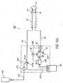
- FIG. 1 an exemplary arrangement of a pump 20 for a phacoemulsification system is shown.
- Pump 20 includes a pump motor 22 and a roller head 24 containing one or more rollers 26. Pump 20 may be used in combination with a cassette 28 having an elastomeric sheet 30 applied to the exterior of a relatively rigid body or substrate 32.
- Pump motor 22 may be a stepper or DC servo motor. Roller head 24 is attached to a shaft 34 of pump motor 22 such that pump motor 22 rotates roller head 24 in a plane generally perpendicular to the axis A-A of shaft 34. Shaft 34 may also contain a shaft position encoder 36.
- Sheet 30 of cassette 28 contains a fluid channel 38 that may be molded therein, channel 38 being configured to be generally planar and arcuate in shape (within the plane). Fluid channel 38 has a radius approximating that of rollers 26 about shaft 34.
- Cassette 28 is designed to be mounted in a cassette receiver 36 of a console 40 (as shown in FIG. 2 ). Cassette 28 operatively couples console 40 to a handpiece 42 (an exemplary schematic arrangement of handpiece 42 is shown in FIG. 3 ).
- Handpiece 42 generally includes an infusion sleeve 44 and a tip member 46, whereby tip member 46 is positioned coaxially within infusion sleeve 44. Tip member 46 is configured for insertion into an eye 47.
- Infusion sleeve 44 allows irrigation fluid to flow from console 40 and/or cassette 28 into the eye. Aspiration fluid may also be withdrawn through a lumen of tip member 46, with console 40 and cassette 28 generally providing aspiration/vacuum to tip member 46.
- the irrigation and aspiration functions of phacoemulsification system 10 are hereby referred to as a phaco fluidic system 11.
- Infusion sleeve 44 of handpiece 42 is connected to an irrigation source 48, which contains an irrigation fluid, by suitable tubing (i.e., irrigation line 50).
- irrigation source 48 may be a pressurized irrigation source (e.g., a bag of irrigation fluid that is selectively compressed to deliver irrigation fluid to an irrigation supply line).
- Tip member 46 is connected to an input port 53 of a pump, such as pump 20, by a length a suitable tubing (i.e., aspiration line 52).
- An aspiration exhaust line 54 extends from pump 20.
- aspiration exhaust line 54 is fluidly connected to a drain line reservoir 56. Reservoir 56 may also drain into an optional drain bag 58. Alternatively, as shown in phantom, exhaust line 54' may be fluidly connected directly to drain bag 58.
- An aspiration vent line 60 is fluidly connected between aspiration line 52 and aspiration exhaust line 54. Vent line 60 is configured as a bypass circuit.
- a vent valve 62 to be discussed in further detail below, is fluidly connected to aspiration vent line 60 so as to selectively control the aspiration pressure within aspiration line 52.
- a pressure sensor 63 is also in fluid communication with aspiration line 52 to detect aspiration pressure within aspiration line 52. Pressure sensor 63 is also operatively connected to a control system in console 40. The control system may be configured to provide pre-set aspiration pressure levels for fluidics system 11, as will be explained below in further detail.
- irrigation source 48 which may be pressurized, is fluidly connected to handpiece 42 by irrigation line 50.
- An irrigation valve 64 is fluidly connected to and positioned between irrigation line 50 and infusion sleeve 44. Irrigation valve 64 provides selective on/off control of irrigation fluid in irrigation line 50.
- Vent valve 62 is configured to provide a variable orifice size within vent line 60 to selectively modulate aspiration within aspiration line 52. More specifically, use of a variable vent valve 62 enables unidirectional rotation of pump 20 in a first direction to generate flow/vacuum, while permitting a mechanism for dynamically controlling aspiration pressure to handpiece 42.
- vent valve 62 may be configured as a multi-position rotary type valve that would allow predictable and precise control of the orifice size based on angular position of vent valve 62 within vent line 60.
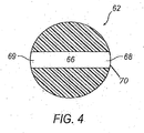
- vent valve 62 An exemplary configuration of vent valve 62 is shown in FIG. 4 .
- multi-position vent valve 62 includes a channel 66 defined by first and second openings 68 and 69. While channel 66 is shown in FIG. 4 as being generally uniformly sized from first opening 68 to second opening 69, it is understood that channel 66 may be configured with a variable size.
- first 68 and second openings 69 may be configured with a diameter that is larger than a central portion of channel 66 such that first and second openings 68 and 69 flare outwardly toward a periphery 70 of vent valve 62.
- vent valve 62 is selectively rotatable in an aspiration circuit, such that the angular position of channel 68 is selectively moveable within vent line 60. Such movement may full open, partially occlude, and/or completely occlude, first and second opening 68 and 69 so as to selectively control the aspiration pressure within aspiration line 52.
- Pressure sensor 63 is operably connected to a control system mounted in console 40. Pressure sensor 63 detects and communicates pressure changes in aspiration line 52 during operation of the phacoemutsification machine.
- predetermined pressure thresholds can be set within the control system such that when pressure readings from pressure sensor 63 exceed those thresholds, the control system may selectively modify the aspiration pressure within aspiration line 52. For example, if the pressure sensor 63 detects that the aspiration pressure has exceed the predetermined pressure threshold, console 40 triggers movement of vent valve 62 within vent line 60 by a predetermined amount to permit venting of aspiration line 52 sufficient to drop the aspiration pressure below the pre-set threshold.
- pressure sensor 63, vent valve 62 and the control system cooperate to permit real-time modulation of aspiration within aspiration line 52 which permits a higher maximum aspiration level to be utilized, but still providing effective occlusion break surges.
- vent valve 62 is positioned such that first and second openings 68 and 69 are positioned out of alignment with vent line 60.
- vent valve 62 is in a "fully closed” position thereby blocking vent line 60 and providing unimpeded aspiration pressure to aspiration line 52.
- pressure sensor 63 detects that aspiration pressure has increased within aspiration line 52 above the threshold level, vent valve 62 may be selectively moved by a predetermined amount so as to move first and second openings 68 and 69 into at least partial alignment, thereby partially opening aspiration exhaust line 54/54'.
- Vent valve 62 is operably connected to an actuator, such as a motor 71, having an angular position encoder (such as encoder 36).
- a motor 71 includes a stepper motor.
- the controller may automatically operate motor 71 to rotate vent valve 62 to a predetermined angular position, thereby quickly changing aspiration pressure within aspiration line 52.
- the controller in cooperation with a pressure sensor positioned in irrigation line 50, may be configured to detect and minimize an occlusion break onset. More specifically, vent valve 62 may be automatically rotated by motor 71 to reduced aspiration pressure within aspiration line 52. This function would operate to lessen an effect of a post occlusion break surge. Because vent valve 62 permits selective and dynamic control of aspiration levels within aspiration line 52, vacuum levels may be easily modulated for the user's preference, thereby providing quicker and more efficient lens removal.
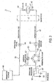
- Phaco fluidics system 100 includes many of the same components as shown and described above in connection with FIG. 3 . Accordingly, like components have been given the same reference numbers. For a description of those components, reference is made to the discussion above with respect to FIG. 3 .
- an aspiration exhaust line 54' extends from pump 20 and is fluidly connected to a drain bag 58.
- phaco fluidics system 100 may include an exhaust line 54 that is fluidly connected to a drain line reservoir.
- An aspiration vent line 160 is fluidly connected between aspiration line 52 and atmosphere 102.
- a variable vent valve 62 is fluidly connected to aspiration vent line 160 so as to selectively control the aspiration pressure within aspiration line 52.
- Pressure sensor 63 is also in fluid communication with aspiration line 52.
- vent valve 62 is configured to provide a variable orifice size to selectively modulate vacuum, thereby allowing unidirectional rotation of pump 20 to generate flow/vacuum, while permitting selective control of vacuum/aspiration to handpiece 42 based on angular position of vent valve 62.
- Vent valve 62 is configured to be selectively rotatable to dynamically control aspiration within aspiration line 52.
- pressure sensor 63 is operably connected to a control system mounted in console 40.
- Pressure sensor 63 detects and communicates pressure changes in aspiration line 52 during operation of the phacoemulsification machine.
- predetermined pressure thresholds are set by the users within the control system. Accordingly, when pressure sensor 63 detects an aspiration pressure level that exceeds the pre-set thresholds, the control system moves vent valve 62 by a predetermined amount to reduce the aspiration pressure within aspiration line 52 by positioning channel 66 in vent valve 62 in at least partial communication with atmosphere 102. It is also understood that vent valve 62 may be fully opened to atmosphere 102 to effectively fully vent aspiration line 52.
- vent valve 62 may be selectively moved to fully close vent line 160 to atmosphere 102, thereby effectively providing full vacuum/aspiration pressure in aspiration line 52 to tip member 46. Movement of vent valve 62 to selectively adjust the aspiration pressure within aspiration line 52 may be accomplished either manually (e.g., selective operation of a footswitch treadle based on prior user settings) or automatically by motor 71 that is operatively connected to the control system.
- Phaco fluidics system 200 includes many of the same components as shown and described above in connection with FIGS. 3 and 5 . Accordingly, like components have been given the same reference numbers. For a detailed discussion of those components, reference is made to the discussion above with respect to FIG. 3 .
- An aspiration vent line 260 is fluidly connected between aspiration line 52 and a vent pressure source 202.
- suitable vent pressure sources include, but are not limited to, a pressurized fluid or saline.
- Variable vent valve 62 is fluidly connected to aspiration vent line 260 so as to selectively control the aspiration pressure within aspiration line 52.
- Pressure sensor 63 is also in fluid communication with aspiration line 52.
- Vent valve 62 is configured to provide a variable orifice size to selectively modulate vacuum, thereby allowing unidirectional rotation of pump 20 in a first direction to generate flow/vacuum, while permitting selective control of vacuum/aspiration to handpiece 42 based on the angular position of vent valve 62.
- Pressure sensor 63 is operably connected to a control system mounted in console 40 and detects and communicates pressure changes in aspiration line 52 during operation of the phacoemulsification machine.
- predetermined pressure thresholds are set within the control system such that when pressure readings from pressure sensor 63 exceed those thresholds, vent valve 62 is moved by a predetermined amount to reduce the aspiration pressure within aspiration line 52. This is accomplished by positioning channel 66 in vent valve 62 in at least partial communication with a vent pressure source 202, thereby opening vent line 260, and permitting pressurized fluid (for example) to enter into aspiration line 52.
- Vent valve 62 may be fully opened to vent pressure source 202 to effectively negate aspiration pressure in aspiration line 52, without need to interrupt pump 20 operation.
- vent valve 62 may be fully closed, i.e., channel 66 being positioned completely out of alignment with vent line 260, such that vent pressure source 202 is not in communication with vent line 260. This configuration effectively provides full vacuum/aspiration pressure in aspiration line 52 to tip member 46.
- Phaco fluidics system 300 includes many of the same components as shown and described above in connection with FIGS. 3 and 5-6 . Accordingly, like components have been given the same reference numbers. For a detailed discussion of those components, reference is made to the discussion above with respect to FIG. 3 .
- An aspiration vent line 360 is fluidly connected between aspiration line 52 and irrigation line 50.
- Variable vent valve 62 is fluidly connected to aspiration vent line 360 so as to selectively control the aspiration pressure within aspiration line 52.
- a pressure sensor 63 is also in fluid communication with aspiration line 52.
- Vent valve 62 is configured to provide a variable orifice size to selectively modulate vacuum, thereby allowing uninterrupted unidirectional rotation of pump 20 in a first direction to generate flow/vacuum, while permitting selective control of vacuum/aspiration to handpiece 42 based on angular position of vent valve 62.
- Pressure sensor 63 is operably connected to a control system mounted in console 40 and detects and communicates pressure changes in aspiration line 52 during operation of the phacoemulsifcation machine.
- predetermined pressure thresholds are set within the control system such that when pressure readings from pressure sensor 63 exceed those thresholds, vent valve 62 may be selectively moved by a predetermined amount to reduce, for example, the aspiration pressure within aspiration line 52.
- channel 66 in vent valve 62 is moved so as to be in at least partial alignment with vent line 360, thereby placing aspiration line 52 in at least partial communication with irrigation line 50 by a predetermined amount to automatically control the level of vacuum/aspiration pressure in aspiration line 52 based on information received from sensor 63.
- vent valve 62 may be fully opened to irrigation line 50 to effectively negate aspiration pressure in aspiration line 52.
- vent valve 62 may be positioned so as to fully close irrigation line 50, thereby effectively providing full vacuum/aspiration pressure in aspiration line 52 to tip member 46. In such a configuration, channel 66 is fully aligned with vent line 360.
- Phaco fluidics system 400 includes many of the same components as shown and described above in connection with FIGS. 3 and 5-7 .
- Phaco fluidics system 400 includes infusion sleeve 44 of handpiece 42 that is connected to an irrigation source 448 by irrigation line 50.
- Phaco fluidics system 400 may also include a multi-position irrigation valve 464 that is fluidly connected to and positioned at a three-way junction between an irrigation supply line 473, irrigation line 50 and a shunt line 476.
- An irrigation line pressure sensor 475 may be positioned in irrigation line 50 between shunt line 476 and infusion sleeve 42.
- Handpiece 42 may also be provided with a handpiece pressure sensor 443.
- irrigation source 448 may be any suitable irrigation source, in one exemplary arrangement, irrigation source 448 is pressurized. More specifically, an irrigation bag 449 may be provided that is positioned against a platform 451 and a pressurizing force, represented by arrows 453, is applied to irrigation bag 449 so as to force infusion fluid out of irrigation bag 449 and into irrigation supply line 473. Other pressurized fluid systems are also contemplated.
- Tip member 46 is connected to input port 53 of a peristaltic pump 420 by aspiration line 52.
- pump 420 is a pump such as described in U.S. Patent Application Publication No. 20100286651 , entitled “Multiple Segmented Peristaltic Pump and Cassette” or a pump such as described in U.S. Patent No. 6,962,488 , entitled "Surgical Cassette Having an Aspiration Pressure Sensor, the contents of both of which are incorporated by reference in their entirety.
- Aspiration exhaust line 54 extends from pump 420 and is fluidly connected to a vent reservoir 456. Vent reservoir 546 is fluidly connected to a drain bag 58.
- An aspiration vent line 460 is fluidly connected between aspiration line 52 and vent reservoir 456, so as to bypass pump 420.
- Variable vent valve 62 is fluidly connected to aspiration vent line 460 so as to selectively control the aspiration pressure within aspiration line 52.
- An aspiration pressure sensor 63 is also in fluid communication with aspiration line 52.
- Vent valve 62 is configured to provide a variable orifice size within vent line 460 to selectively modulate vacuum, thereby allowing unidirectional rotation of pump 420 in a first direction to generate flow/vacuum, while permitting selective control of vacuum/aspiration to handpiece 42 based on the angular position of vent valve 62.
- pressure sensor 63 is operably connected to a control system mounted in console 40. Pressure sensor 63 detects and communicates pressure changes in aspiration line 52 during operation of the phacoemulsification machine.
- predetermined pressure thresholds are set within the control system such that when pressure readings from pressure sensor 63 exceed those thresholds, vent valve 62 may be selectively moved by a predetermined amount to reduce the aspiration pressure within aspiration line 52. This is accomplished by positioning channel 66 in vent valve 62 in at least partial communication with vent line 460. Because vent line 460 is operably connected to vent reservoir 456, the partial communication of channel 66 with vent line 460 effectively reduces aspiration pressure within aspiration line 52.
- vent valve 62 may be accomplished by motor 71 that is connected to vent valve 62. More specifically, motor 71 may be configured to automatically move vent valve 62 by a predetermined amount to automatically control the level of vacuum/aspiration pressure in aspiration line 52 based on information received from sensor 63. It is understood that vent valve 62 may be oriented to a fully opened position to fully vent aspiration line to vent reservoir 456 to effectively close off input port 53 to pump 420. Alternatively, it is also understood that vent valve 62 may be fully closed, i.e., such that channel 66 is out of alignment with vent line 460, thereby closing vent reservoir 456 to aspiration line 52, thereby effectively providing full vacuum/aspiration pressure in aspiration line 52 to tip member 46.
- phaco fluidics system 400 also provides a multi-position irrigation valve 464 that is positioned at a junction between irrigation supply line 473, irrigation line 50 and shunt line 476.
- irrigation valve 464 is configured as a rotary valve that may be operatively positioned to selectively control irrigation in phaco fluidics system 400.
- multi-position irrigation valve 464 includes an intersecting channel configuration 474. More specifically, channel 474 includes a first branch 474A, a second branch 474B and a third branch 474C. While shown as having a T-shaped configuration, it is understood that other intersecting configuration may be utilized, depending on the configuration of the various fluid lines in fluidics system 400.
- irrigation valve 464 In operation, as shown in FIG. 8 , when irrigation valve 464 is oriented such that first branch 474A is fully aligned with irrigation supply line 473 and third branch 474B is fully aligned with irrigation line 50, but second branch 474C is oriented out of alignment with shunt line 476, normal, full irrigation flow is provided to irrigation line 50.
- irrigation valve 464 may be selectively rotated such that first branch 474A is fully aligned with shunt line 476 and third branch 474C is fully aligned with irrigation supply line 473. Accordingly, when phaco fluidics system 400 is operated, fluid from irrigation supply 448 is directed to drain bar 58.
- irrigation valve 464 may be selectively rotated such that second arm 474B is fully aligned with shunt line 476 and third arm 474C is fully aligned with irrigation line 50.
- irrigation valve 464 may be configured to be selectively positioned so as to effectively control the amount of fluid to be delivered to eye 47. Indeed, in some patients, a full irrigation flow (such a shown in FIG. 8 ), may lead to patient discomfort, while a controlled opening whereby certain branches of irrigation valve 464 is positioned at various angular positions with respect to irrigation line 50 may be desirable. Thus, similar to vent valve 62, irrigation valve 464 may also be configured for variable irrigation delivery.
- FIG. 9B Another alternative configuration for a multi-position irrigation valve is shown in FIG. 9B .
- a multi-position irrigation valve 464' is provided having an L-shaped pathway formed therein.
- Multi-position irrigation valve 464' includes a first branch 474A' and a second branch 474B'. Use of multi-position irrigation valve 464' will be described below in connection with FIGS. 10A-10C .
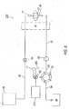
- Phaco fluidics system 400' for use with a positive displacement pumping system is shown.
- Phaco fluidics system 400' includes many of the same components as shown and described above in connection with FIGS. 3 and 5-8 .
- the components inside of the dashed box may at least partially be included in a fluidics cassette configured to be secured to a surgical console.
- Phaco fluidics system 400' includes infusion sleeve 44 of handpiece 42 that is connected to an irrigation source 448 by irrigation line 50.
- a multi-position irrigation valve 464' is fluidly connected to and positioned at a three-way junction between an irrigation supply line 473, irrigation line 50 and a shunt line 476.
- An irrigation line pressure sensor 475 may be positioned in irrigation line 50 between irrigation supply 448 and handpiece 42.
- irrigation source 448 may be any suitable irrigation source, in one exemplary arrangement, irrigation source 448 includes an irrigation container that utilizes gravity to force infusion fluid out of the irrigation container and into irrigation supply line 473.
- Multi-position irrigation valve 464' may be configured as a rotary valve that may be operatively positioned to selective control irrigation in phaco fluidics system 400'.
- first branch 474A' is aligned with irrigation line 50
- second branch 474B' is oriented so as to be out of alignment with irrigation supply line 473 and shunt line 476, no irrigation is supplied to irrigation line 50.
- irrigation valve 464' may be selectively rotated such that first branch 474A' is at least partially aligned with irrigation supply line 473 and second branch 474B' is at least partially aligned with irrigation line 50. Accordingly, fluid from irrigation supply 448.is directed through irrigation supply line 473, to irrigation line 50 through irrigation valve 464' and to handpiece 42. As with irrigation valve 464, it may be desirable to selectively position first and second branches 474A' and 474B' so as to effectively control the amount of fluid to be delivered to eye 47.
- irrigation line 50 may be subject to a controlled opening with irrigation supply line 473, whereby first and second branches 474A' and 474B' of irrigation valve 464' is positioned at various angular positions to provide less than full irrigation flow through irrigation line 50.
- irrigation valve 464' may also be configured for variable irrigation delivery.
- FIG. 10C illustrates a priming operation for irrigation supply 448 of phaco fluidics system 400' by actuation of irrigation valves 464'. More specifically, irrigation valve 464' may be selectively rotated such that first branch 474A' is at least partially aligned with shunt line 476 and second branch 474B' is at least partially aligned with irrigation supply line 473. Accordingly, when phaco fluidics system 400 is operated, fluid from irrigation supply 448 is directed to drain bag 58.
- multi-position irrigation valves 464 and 464' have both been described in connection with a phaco fluidics system 400 that also incorporates a variable vent valve 62, it is understood that the scope of the present disclosure is not limited to a phaco fluidics system 400 that includes both a multi-position irrigation valve 464/464' and a variable vent valve 62. Further, multi-position irrigation valves 464/464' are capable of operating in an "on/off" type fashion, or, as described above, multi-position irrigation valves 464/464' may also be configured to provide variable orifice so as to selectively control the amount of irrigation, in a manner similar to that which has been previously described in connection with variable vent valve 62.
- the amount of irrigation to be provided to handpiece 42 from irrigation supply line 473 may be selectively controlled by a multi-position variable irrigation line, such that less than full irrigation from irrigation supply line 473 may be supplied to irrigation line 50 (and thus handpiece 42).
- multi-position variable irrigation valve 464/464' is selectively rotated so as to provide only partial communication with both irrigation supply line 473 and irrigation line 50.
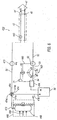
- Phaco fluidics system 500 includes many of the same components as shown and described above in connection with FIGS. 3 , and 5-10 . Accordingly, like components have been given the same reference numbers. For a detailed discussion of those components, reference is made to the discussion above with respect to FIG. 3 .
- Phaco fluidics system 500 includes infusion sleeve 44 of handpiece 42 that is connected to irrigation source 48 by an irrigation supply line 549 that is fluidly connected to an irrigation line 50.
- An aspiration exhaust line 54 extends from pump 20.
- aspiration exhaust line 54 is fluidly connected to a drain line reservoir 56. Reservoir 56 may also drain into an optional drain bag 58. Alternatively, as shown in phantom, exhaust line 54' may be fluidly connected directly to drain bag 58.
- An aspiration vent line 560 is fluidly connected between aspiration line 52 and irrigation line 50.
- a multi-purpose proportional valve 562 is fluidly connected between aspiration vent line 560 and irrigation line 50 so as to selectively control the aspiration pressure within aspiration line 52 and irrigation flow within irrigation line 50.
- Pressure sensor 63 is also in, fluid communication with aspiration line 52.
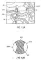
- Multi-purpose valve 562 is configured to provide a variable orifice size to selectively modulate aspiration, thereby allowing unidirectional rotation of pump 20 in a first direction to generate flow/vacuum, while permitting selective control of vacuum/aspiration to handpiece 42 based on the angular position of multi-purpose valve 62, as well as providing irrigation control. More specifically, in one exemplary configuration, referring to FIGS. 12A-12B , the body of multi-purpose valve 562 is defined by a periphery 570. The body has a first flow path 563A formed in one portion of the periphery 570 and a second flow path 563B formed in another portion of the periphery 570.
- multi-purpose valve 562 is selectively rotatable within a groove 600 formed in cassette 28. More specifically, operably connected to groove 600 are a plurality of fluid lines that are selectively connectable to one another via the angular position of multi-purpose valve 562.
- multi-purpose valve 562 serves to operatively connect irrigation supply line 549, irrigation line 50, aspiration line 52 and aspiration exhaust line 54/54' via first and second flow paths 563A, 563B.
- Multi-purpose valve 562 is moveable within groove 600 so as to provide a variety of connection arrangements with respect to aspiration line 52, irrigation line 50, irrigation supply line 549 and aspiration exhaust line 54/54' may be achieved, as will be explained in further detail below.
- Pressure sensor 63 is operably connected to a control system mounted in console 40 and is configured to detect and communicate pressure changes in aspiration line 52 during operation of the phacoemulsification machine.
- predetermined pressure thresholds are set within the control system such that when pressure readings from pressure sensor 63 exceed those thresholds, the control system may selectively move multi-purpose valve 562 by a predetermined amount to reduce the aspiration pressure within aspiration line 52. More specifically, second flow path 563B in multi-purpose valve 562 is moveable with respect to aspiration vent line 560.
- multi-purpose valve 562 may be positioned within groove 600 and selectively rotated such that second flow path 563B fully closes aspiration vent line 560 off from aspiration line 52, such that full vacuum, as dictated by the user's pre-selected pressure settings, is provided. However, if pressure has increased within aspiration line 52 by an undesirable amount (such as, for example, because of an occlusion break surge), multi-purpose valve 562 may be selectively moved by a predetermined amount such that second flow path 563B operatively connects aspiration line 54/54' directly to aspiration line 52, via aspiration vent line 560, thereby bypassing pump 20. This action quickly and effectively restores the aspiration pressure within aspiration line 52 to the predetermined acceptable amount, without requiring pump reversal.
- multi-purpose valve 562 may be operably connected to a footswitch treadle. Accordingly, the user may operate the footswitch treadle to rotate multi-purpose valve 562 to selectively vent (e.g., by lifting his/her foot from the treadle) aspiration line 52.
- the footswitch treadle may be configured to rotate multi-purpose valve 562 by a predetermined amount and in a predetermined direction, based on the control system settings, based on user input. Due to the configuration of second flow path 563B, a variety of aspiration pressures may be achieved by selective movement of multi-purpose valve 562. In some exemplary situations, it may be desirable to fully open exhaust line 54/54', thereby fully venting aspiration line 52.
- multi-purpose valve 562 is operably connected to a motor 71, such as a stepper motor, having an angular position encoder (such as encoder 36).
- a motor 71 such as a stepper motor, having an angular position encoder (such as encoder 36).
- the controller automatically operates motor 71 to rotate multi-purpose valve 562 to a predetermined position, thereby quickly changing aspiration pressure within aspiration line 52.
- the controller in cooperation with pressure sensor 63, may be configured to detect an occlusion break onset, multi-purpose valve 562 may be automatically rotated by motor 71 to reduced aspiration pressure within aspiration line 52 below predetermined settings. This function would operate to lessen the post occlusion surge. Because multi-purpose valve 562 permits selective and dynamic control of aspiration levels within aspiration line 52, higher vacuum rates may be selected and employed by the user for quicker and more efficient lens removal.
- multi-purpose valve 562 In addition to selectively controlling the aspiration levels within the system 500, multi-purpose valve 562 also serves an additional purpose, namely controlling irrigation through irrigation line 50. More specifically, first flow path 563A is configured to selectively connect irrigation supply line 549 to irrigation line 50 when first flow path 563A is in communication with both irrigation supply line 549 and irrigation line 50. However, multi-purpose valve 562 may be selectively rotated such that first flow path 563A is placed out of communication with irrigation supply line 549, thereby effectively closing off irrigation.
- multi-purpose valve 562 also permits the selective control of the aspiration level while simultaneously controlling irrigation.
- multi-purpose valve 562 and fluid lines 549, 50, 54/54', and 52 are configured such that when first flow path 563A is in communication with both irrigation line 50 and irrigation supply line 549, second flow path 563B is only in communication with exhaust line 54/54', leaving aspiration line 52 closed to exhaust line 54/54'. In this arrangement, irrigation is supplied to handpiece 42 and vent line 560 is closed.
- multi-purpose valve 562 may be rotated slightly from the "irrigation line open, vent line closed” position such that second flow path 563B is open to both aspiration line 52 and exhaust line 54/54', while first flow path 563A is in communication with both irrigation line 50 and irrigation supply line 549.
- irrigation is being supplied to handpiece 42 and aspiration line 52 is operatively connected to exhaust line 54/54' thereby reducing, if not eliminating aspiration pressure within aspiration line 52.
- This design effectively eliminates a valve element from system 500, while still providing for selectively varying aspiration pressure and selectively controlling irrigation.
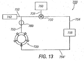
- Aspiration circuit 700 employs both displacement-based and/or vacuum-based aspiration modes.
- Aspiration circuit 700 includes an aspiration line 752 that fluidly connects to handpiece 742 to either an input port 753 of peristaltic pump 720 or an input port 731 of a venturi reservoir 760.
- Aspiration exhaust lines 754/754' extend from input port 731 of venturi reservoir 760 and input port 753 of peristalitic pump 720, respectively.
- aspiration circuit 700 employs a multi-purpose valve 732 that is disposed within a sealed groove of a cassette (similar to that shown in FIG. 12A above) that provides both functions.
- multi-purpose valve 732 is configured with a channel 763 that is defined by a first opening 765 and a second opening 767.
- second opening 767 may be configured with an outwardly extending flare.
- channel 763 may be configured with a triangular shape that flares outwardly toward a periphery 770 of multi-purpose valve 732.
- First opening 765 is positioned transverse to channel 763.
- Second opening is formed through a periphery 770 of multi-purpose valve 732.
- multi-purpose valve 732 may be positioned such that aspiration is delivered to aspiration line 752 by pump 720.
- multi-purpose valve 732 is selectively rotated such that input line 731 to venturi reservoir is closed and aspiration exhaust line 754 is closed off from aspiration line 752.
- full aspiration is provided by pump 720.
- a pressure sensor 769 may be positioned in input line 753 to detect and monitor the pressure in aspiration line 752.
- Pressure sensor 769 is operably connected to a control system mounted in a console.
- Pressure sensor 769 detects and communicates pressure changes in aspiration line 752 during operation of the phacoemutsification machine.
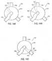
- predetermined pressure thresholds can be set within the control system such that when pressure readings from pressure sensor 769 exceed those thresholds, the system prompts movement of multi-purpose valve 732 by a predetermined amount to reduce the aspiration pressure within aspiration line 52. More specifically, referring to FIG. 14B , multi-purpose valve 732 may be rotated such that second opening 767 of channel 763 is in at least partial fluid communication with aspiration exhaust line 754.
- multi-purpose valve 732 may be selectively moved by a predetermined amount so as to partially open aspiration exhaust line 754, as shown in FIG. 14B . This action quickly and effectively restores the aspiration pressure within aspiration line 752 to the predetermined acceptable amount, without requiring pump reversal. It is understood, however, that channel 763 may be rotated such that aspiration line 752 is fully opened to aspiration exhaust line 754, if need be
- multi-purpose valve 732 may also be used to switch aspiration source from pump 720 to venturi reservoir 760.
- channel 763 is positioned such that second opening 767 is in communication with input 731 of venturi reservoir 760, thereby connecting aspiration line 752 to venturi reservoir 760.
- aspiration exhaust line 754 is sealed off from aspiration line 752.
- a fluidics system for use in a surgical system may include an aspiration circuit (comprising an aspiration line operatively connected to a surgical instrument, an aspiration exhaust line operatively connected to a waste receptacle, an aspiration vent line connected at a first end to the aspiration line, and a selectively variable valve operatively connected to the aspiration vent line (wherein the variable valve may be selectively actuated to selectively change aspiration pressure within the aspiration line)) and an irrigation circuit (comprising an irrigation source, an irrigation supply line connected to the irrigation source, and an irrigation line having a first end operatively connected to the irrigation supply line and a second end operatively connected to the surgical device).
- an aspiration circuit comprising an aspiration line operatively connected to a surgical instrument, an aspiration exhaust line operatively connected to a waste receptacle, an aspiration vent line connected at a first end to the aspiration line, and a selectively variable valve operatively
- the fluidics system may further include a shunt path, wherein a first end of the shunt path is operatively connected to the irrigation supply line and a second end of the shunt path is connected to the waste receptacle.
- the fluidics system may further include a selectively positionable irrigation valve that operatively connects the irrigation supply line, the irrigation line, and the shunt path such that the selectively positionable irrigation valve may be moved to direct irrigation from the irrigation supply line.
- the irrigation valve may be a rotary valve and include an intersecting channel formed therein, the channel defining a first branch, a second branch, and a third branch.
- the irrigation valve is selectively moveable between a first position, a second position and a third position, wherein in the first position, the first branch is positioned in communication with the irrigation supply line and the second branch is positioned in communication with the irrigation line; wherein in the second position, the first branch is positioned in communication with the shunt path and the third branch is in communication with the irrigation supply line; and wherein in the third position, the first branch is positioned in communication with the irrigation line, the second branch is positioned in communication with irrigation supply line and the third branch is positioned in communication with the shunt path.
- variable valve may also be connected to the irrigation line such that the variable valve may be selectively moved to selectively interrupt fluid flow in the irrigation line and to selectively vary aspiration pressure within the aspiration line.
- variable valve may be configured with first and second flow paths formed therein, wherein the first flow path may be selectively aligned with the irrigation supply line and the irrigation line to open the irrigation line to the irrigation supply source, and wherein the second flow path may be selectively aligned with the aspiration line and the aspiration exhaust line to selectively vary aspiration pressure within the aspiration line.
- an aspiration circuit for a fluidics system for selectively controlling aspiration may include an aspiration line operatively connected to a surgical instrument, a first aspiration exhaust line operatively connected to a waste receptacle, a second aspiration exhaust line operatively connected to a waste receptacle, a displacement-based aspiration source operatively connected to the first aspiration exhaust line, a vacuum-based aspiration source operatively connected to the second aspiration exhaust line, and a selectively variable valve operatively connected to both the displacement-based aspiration source and the vacuum-based aspiration source; wherein the variable valve may be actuated to selectively change aspiration pressure within the aspiration line when the displacement-based aspiration source is employed.
- variable valve may be selectively actuated to provide aspiration pressure to the aspiration line from the vacuum-based aspiration source.
- the displacement-based aspiration source is a peristaltic pump and the vacuum-based aspiration source includes a venturi reservoir.
- the variable valve further comprises a valve body that includes a channel that is defined by a first opening and a second opening, wherein the first opening is positioned transverse to the length of the channel and wherein the second opening is formed through a periphery of the valve body.
- the invention also provides an irrigation circuit for a fluidics system and a fluidics cassette in accordance with the following paragraphs numbered 12-20:
Claims (9)
- Ein Absaugkreis für ein Fluidiksystem (11) zum selektiven Steuern einer Absaugung, der umfasst:eine Absaugleitung (52), die operativ mit einem chirurgischen Instrument (42) verbunden ist, wobei eine Absaugauslassleitung (54) operativ mit einem Abfallbehältnis (58) verbunden ist;eine Absaugbelüftungsleitung (60), die an einem ersten Ende mit der Absaugleitung verbunden ist; undein selektiv änderbares Belüftungsventil (62), das operativ mit der Absaugbelüftungsleitung verbunden ist, wobei das änderbare Belüftungsventil selektiv bewegt sein kann, um selektiv einen Absaugdruck innerhalb der Absaugleitung zu ändern,wobei das Belüftungsventil (62) ein Drehventil ist, das weiterhin eine Eingangsöffnung (68), eine Ausgangsöffnung (69) und einen Kanal (66) umfasst, der die Eingangsöffnung mit der Ausgangsöffnung verbindet;wobei das Belüftungsventil (62) selektiv gedreht sein kann, um selektiv den Kanal (66) in eine zumindest teilweise Verbindung mit der Absaugbelüftungsleitung (60) zu legen.
- Der Absaugkreis nach Anspruch 1, wobei die Absaugbelüftungsleitung (60) an einem zweiten Ende mit der Absaugauslassleitung (54) verbunden ist.
- Der Absaugkreis nach Anspruch 1, wobei die Absaugbelüftungsleitung (60) an einem zweiten Ende mit dem Freien verbunden ist.
- Der Absaugkreis nach Anspruch 1, wobei die Absaugbelüftungsleitung (60) an einem zweiten Ende mit einer Belüftungsdruckquelle eines unter Druck stehenden Fluides oder einer Saline verbunden ist.
- Der Absaugkreis nach Anspruch 1, wobei die Absaugbelüftungsleitung (60) an einem zweiten Ende mit einer Spülungsleitung (50) verbunden ist.
- Der Absaugkreis nach Anspruch 1, der weiterhin umfasst:einen Drucksensor (63) und einen Aktuator, wobei der Drucksensor operativ mit der Absaugleitung (52) verbunden ist und der Aktuator operativ mit dem Belüftungsventil (62) verbunden ist, wobei der Drucksensor und Aktuator mit einer Steuerung (40) verbunden sind, und wobei die Steuerung betriebsbereit ist, um den Aktuator zu veranlassen, das Belüftungsventil als Antwort auf vorbestimmte, von dem Drucksensor detektierte Druckwerte zu bewegen, um den Absaugdruck innerhalb der Absaugleitung zu variieren.
- Der Absaugkreis nach Anspruch 6, wobei der Aktuator ein Motor (71) ist.
- Der Absaugkreis nach Anspruch 1, wobei das variable Belüftungsventil (62) derart operativ mit der Spülungsleitung (50) verbunden ist, dass das variable Belüftungsventil selektiv bewegt sein kann, um selektiv einen Fluidstrom in der Spülungsleitung zu unterbrechen und selektiv einen Absaugdruck innerhalb der Absaugleitung (52) zu variieren.
- Der Absaugkreis nach Anspruch 8, wobei das variable Belüftungsventil (562) mit darin gebildeten ersten und zweiten Strömungswegen eingerichtet ist, wobei der erste Strömungsweg selektiv, und zumindest teilweise, auf eine Spülungsversorgungsleitung und die Spülungsleitung (50) ausgerichtet sein kann, um die Spülungsleitung zu einer Spülungsversorgungsquelle zu öffnen, und wobei der zweite Strömungsweg selektiv, und zumindest teilweise, auf die Absaugleitung (52) und die Absaugauslassleitung (54) ausgerichtet sein kann, um selektiv den Absaugdruck innerhalb der Absaugleitung zu variieren.
Priority Applications (2)
| Application Number | Priority Date | Filing Date | Title |
|---|---|---|---|
| EP16171180.9A EP3081239B8 (de) | 2011-12-08 | 2012-11-27 | Selektiv bewegliche ventilelemente für absaug- und bewässerungszyklen |
| EP19204998.9A EP3620189A1 (de) | 2011-12-08 | 2012-11-27 | Selektiv bewegliche ventilelemente für absaug- und bewässerungszyklen |
Applications Claiming Priority (2)
| Application Number | Priority Date | Filing Date | Title |
|---|---|---|---|
| US201161568220P | 2011-12-08 | 2011-12-08 | |
| PCT/US2012/066594 WO2013085745A1 (en) | 2011-12-08 | 2012-11-27 | Selectively moveable valve elements for aspiration and irrigation circuits |
Related Child Applications (3)
| Application Number | Title | Priority Date | Filing Date |
|---|---|---|---|
| EP19204998.9A Division EP3620189A1 (de) | 2011-12-08 | 2012-11-27 | Selektiv bewegliche ventilelemente für absaug- und bewässerungszyklen |
| EP16171180.9A Division EP3081239B8 (de) | 2011-12-08 | 2012-11-27 | Selektiv bewegliche ventilelemente für absaug- und bewässerungszyklen |
| EP16171180.9A Division-Into EP3081239B8 (de) | 2011-12-08 | 2012-11-27 | Selektiv bewegliche ventilelemente für absaug- und bewässerungszyklen |
Publications (3)
| Publication Number | Publication Date |
|---|---|
| EP2766064A1 EP2766064A1 (de) | 2014-08-20 |
| EP2766064A4 EP2766064A4 (de) | 2014-12-03 |
| EP2766064B1 true EP2766064B1 (de) | 2016-08-17 |
Family
ID=48572664
Family Applications (3)
| Application Number | Title | Priority Date | Filing Date |
|---|---|---|---|
| EP19204998.9A Pending EP3620189A1 (de) | 2011-12-08 | 2012-11-27 | Selektiv bewegliche ventilelemente für absaug- und bewässerungszyklen |
| EP16171180.9A Active EP3081239B8 (de) | 2011-12-08 | 2012-11-27 | Selektiv bewegliche ventilelemente für absaug- und bewässerungszyklen |
| EP12855496.1A Active EP2766064B1 (de) | 2011-12-08 | 2012-11-27 | Selektiv bewegliche ventilelemente für absaug- und bewässerungszyklen |
Family Applications Before (2)
| Application Number | Title | Priority Date | Filing Date |
|---|---|---|---|
| EP19204998.9A Pending EP3620189A1 (de) | 2011-12-08 | 2012-11-27 | Selektiv bewegliche ventilelemente für absaug- und bewässerungszyklen |
| EP16171180.9A Active EP3081239B8 (de) | 2011-12-08 | 2012-11-27 | Selektiv bewegliche ventilelemente für absaug- und bewässerungszyklen |
Country Status (19)
| Country | Link |
|---|---|
| US (5) | US9561321B2 (de) |
| EP (3) | EP3620189A1 (de) |
| JP (4) | JP2015500698A (de) |
| KR (3) | KR102170110B1 (de) |
| CN (2) | CN108309558B (de) |
| AR (1) | AR089585A1 (de) |
| AU (3) | AU2012348191C1 (de) |
| BR (3) | BR122019028291B1 (de) |
| CA (3) | CA3057786C (de) |
| DK (1) | DK2766064T3 (de) |
| ES (2) | ES2770712T3 (de) |
| IN (1) | IN2014CN04341A (de) |
| MX (1) | MX346230B (de) |
| PH (1) | PH12014501196A1 (de) |
| PL (1) | PL2766064T3 (de) |
| PT (1) | PT2766064T (de) |
| RU (2) | RU2731477C2 (de) |
| TW (3) | TWI580446B (de) |
| WO (1) | WO2013085745A1 (de) |
Families Citing this family (42)
| Publication number | Priority date | Publication date | Assignee | Title |
|---|---|---|---|---|
| CN108309558B (zh) | 2011-12-08 | 2021-02-12 | 爱尔康公司 | 抽吸和灌注回路的可选择性移动阀元件 |
| US9549850B2 (en) | 2013-04-26 | 2017-01-24 | Novartis Ag | Partial venting system for occlusion surge mitigation |
| US10137034B2 (en) | 2013-11-26 | 2018-11-27 | Novartis Ag | Pressure-sensing vitrectomy surgical systems and methods |
| US10537471B2 (en) * | 2014-04-17 | 2020-01-21 | Novartis Ag | Hydraulic pump for ophthalmic surgery |
| US9486562B2 (en) | 2014-10-24 | 2016-11-08 | Integrated Surgical, Llc | Suction device for surgical instruments |
| US9931447B2 (en) * | 2014-12-16 | 2018-04-03 | Novartis Ag | Quick-opening vent valve for phaco fluidics aspiration system |
| US9549851B2 (en) | 2015-01-28 | 2017-01-24 | Novartis Ag | Surgical hand piece with integrated pressure sensor |
| US10926007B2 (en) | 2015-07-13 | 2021-02-23 | Conmed Corporation | Surgical suction device that uses positive pressure gas |
| WO2017011024A1 (en) | 2015-07-13 | 2017-01-19 | Noah Mark Minskoff | Surgical suction device that uses positive pressure gas |
| US11051978B2 (en) | 2016-05-10 | 2021-07-06 | Alcon Inc. | Automated aspiration throttling in vitreoretinal surgery |
| US11432961B2 (en) | 2016-05-17 | 2022-09-06 | Alcon, Inc. | Automated viscous fluid control in vitreoretinal surgery |
| US10702415B2 (en) | 2016-08-18 | 2020-07-07 | Alcon Inc. | Surgical apparatus including aspiration device sensors |
| EP3515519B1 (de) * | 2016-09-20 | 2023-11-01 | Medela Holding AG | Vorrichtung zum absaugen von körperfluiden und zum zuführen einer substanz |
| JP6812721B2 (ja) * | 2016-09-29 | 2021-01-13 | 株式会社ニデック | 眼科装置 |
| CN106730072B (zh) * | 2017-03-15 | 2023-08-11 | 四川大学 | 骨内泄压钉 |
| EP3691707B1 (de) | 2017-10-04 | 2021-11-17 | Johnson & Johnson Surgical Vision, Inc. | System zur erhöhung des irrigationsdrucks und zur aufrechterhaltung des augeninnendrucks während eines nachokklusionsstosses |
| EP3691585B1 (de) | 2017-10-04 | 2023-09-27 | Johnson & Johnson Surgical Vision, Inc. | Systeme zur messung des flüssigkeitsstroms in einem system auf venturi-basis |
| US11071816B2 (en) | 2017-10-04 | 2021-07-27 | Johnson & Johnson Surgical Vision, Inc. | System, apparatus and method for monitoring anterior chamber intraoperative intraocular pressure |
| US20190099526A1 (en) * | 2017-10-04 | 2019-04-04 | Abbott Medical Optics Inc. | Advanced Occlusion Management Methods for a Phacoemulsification System |
| US11116878B2 (en) | 2017-11-16 | 2021-09-14 | Alcon Inc. | Fluidics aspiration system |
| US11065371B2 (en) | 2017-12-14 | 2021-07-20 | Johnson & Johnson Surgical Vision, Inc. | Flow restrictor for surgical device |
| CN108670547B (zh) * | 2018-06-07 | 2020-12-04 | 河源光明眼科医院有限公司 | 白内障手术装置 |
| EP4302791A2 (de) | 2018-09-24 | 2024-01-10 | Stryker Corporation | Systeme und verfahren zur verbesserung der steuerungsreaktion während einer aspiration |
| US11754196B2 (en) | 2018-10-22 | 2023-09-12 | Johnson & Johnson Surgical Vision, Inc. | Electromagnetic actuation of elastomeric valve for fluid flow control |
| CN109602963B (zh) * | 2018-12-29 | 2021-04-13 | 捷锐企业(上海)有限公司 | 吸氧与负压吸引集成模块 |
| US11779694B2 (en) | 2019-04-24 | 2023-10-10 | Johnson & Johnson Surgical Vision, Inc. | Systems and methods for proportional pressure and vacuum control in surgical system |
| EP3968912A1 (de) | 2019-05-17 | 2022-03-23 | Carl Zeiss Meditec Cataract Technology Inc. | Ophthalmische schneidinstrumente mit integrierter absaugpumpe |
| RU2720821C1 (ru) * | 2019-05-21 | 2020-05-13 | Александр Николаевич Епихин | Системы ирригации и аспирации офтальмологического аппарата для катарактальной и витреальной хирургии |
| CA3142864A1 (en) | 2019-06-07 | 2020-12-10 | Carl Zeiss Meditec Cataract Technology Inc. | Multi-stage trigger for ophthalmology cutting tool |
| EP4076568A1 (de) * | 2019-12-17 | 2022-10-26 | Johnson & Johnson Surgical Vision, Inc. | Drehventilanordnung für eine chirurgische kassette |
| CN114980846A (zh) * | 2020-01-14 | 2022-08-30 | 爱尔康公司 | 文丘里外科手术系统中的真空振荡防止 |
| CN113730090A (zh) * | 2020-05-27 | 2021-12-03 | 深圳市钛金时代科技开发有限公司 | 一种整体管道超声乳化套件 |
| US20220008251A1 (en) * | 2020-07-13 | 2022-01-13 | Johnson & Johnson Surgical Vision, Inc. | Aspiration bypass control in a phacoemulsification probe |
| GB2597925A (en) * | 2020-08-03 | 2022-02-16 | Gyrus Medical Ltd | A flow valve position sensor for an electrosurgical device |
| CN116113387A (zh) | 2020-08-14 | 2023-05-12 | 爱尔康公司 | 用于闭塞后涌动缓解的系统和方法 |
| US20220133537A1 (en) * | 2020-11-05 | 2022-05-05 | Johnson & Johnson Surgical Vision, Inc. | Controlling intraocular pressure during phacoemulsification procedures |
| US20220192876A1 (en) | 2020-12-22 | 2022-06-23 | Johnson & Johnson Surgical Vision, Inc. | Module for aspiration and irrigation control |
| US20220339032A1 (en) * | 2021-04-21 | 2022-10-27 | Johnson & Johnson Surgical Vision, Inc. | Evaluation of phacoemulsification devices |
| EP4329643A1 (de) * | 2021-04-27 | 2024-03-06 | Contego Medical, Inc. | Thrombusaspirationssystem und verfahren zur kontrolle von blutverlust |
| US11944340B2 (en) * | 2021-06-11 | 2024-04-02 | Cilag Gmbh International | Suction and irrigation valve and method of priming same in a robotic surgical system |
| WO2023130134A2 (en) * | 2022-01-03 | 2023-07-06 | The General Hospital Corporation | Systems and methods for irrigating an anatomic space |
| KR102491812B1 (ko) * | 2022-09-28 | 2023-01-27 | 운스메디칼 주식회사 | 미세 조정용 압력 조절 장치 |
Citations (18)
| Publication number | Priority date | Publication date | Assignee | Title |
|---|---|---|---|---|
| US3558100A (en) | 1968-01-23 | 1971-01-26 | Eldon E Hulsey | Multiple orifice rotary control valve |
| WO1989003230A1 (en) | 1987-10-14 | 1989-04-20 | The Cooper Companies, Inc. | Surgical irrigation and aspiration system |
| US4944261A (en) | 1989-10-16 | 1990-07-31 | Coates George J | Spherical rotary valve assembly for an internal combustion engine |
| EP0555625A1 (de) | 1992-02-12 | 1993-08-18 | American Cyanamid Company | Absaugsteuervorrichtung |
| US5306237A (en) | 1989-11-06 | 1994-04-26 | Mectra Labs, Inc. | Disposable lavage |
| US5693013A (en) | 1995-01-26 | 1997-12-02 | Hans Geuder Gmbh | Apparatus for aspirating lens debris during cataract operations |
| US5897524A (en) | 1997-03-24 | 1999-04-27 | Wortrich; Theodore S. | Compact cassette for ophthalmic surgery |
| US6258111B1 (en) | 1997-10-03 | 2001-07-10 | Scieran Technologies, Inc. | Apparatus and method for performing ophthalmic procedures |
| EP1356834A2 (de) | 2002-04-25 | 2003-10-29 | Alcon Inc. | Chirurgisches Absaugsystem |
| US20040253129A1 (en) | 1999-08-31 | 2004-12-16 | Sorensen Gary P. | Liquid venting surgical cassette |
| US20070005002A1 (en) | 2005-06-30 | 2007-01-04 | Intuitive Surgical Inc. | Robotic surgical instruments for irrigation, aspiration, and blowing |
| US20070287959A1 (en) | 2006-06-10 | 2007-12-13 | Walter Jonathan T | Ophthalmic Surgical Cassette and System |
| US20080114290A1 (en) | 2006-11-09 | 2008-05-15 | Advanced Medical Optics, Inc. | Reversible peristaltic pump and other structures for reflux in eye surgery |
| US20090018488A1 (en) | 2007-07-09 | 2009-01-15 | Davis Sherman G | Method of Priming a Surgical System |
| US20090182266A1 (en) | 2008-01-10 | 2009-07-16 | Raphael Gordon | Surgical System |
| US20100204645A1 (en) | 2009-02-10 | 2010-08-12 | Tyco Healthcare Group Lp | Enteral Feeding System |
| US20100280439A1 (en) | 2007-11-09 | 2010-11-04 | Carl Zeiss Surgical Gmbh | Surgical system for controlling fluid |
| US20110144567A1 (en) | 2009-12-15 | 2011-06-16 | Alcon Research, Ltd. | Phacoemulsification Hand Piece With Integrated Aspiration Pump and Cartridge |
Family Cites Families (236)
| Publication number | Priority date | Publication date | Assignee | Title |
|---|---|---|---|---|
| US3515155A (en) | 1967-02-24 | 1970-06-02 | Air Reduction | Gas mixture proportioner |
| NL145136C (de) | 1967-07-25 | 1900-01-01 | ||
| US3732858A (en) | 1968-09-16 | 1973-05-15 | Surgical Design Corp | Apparatus for removing blood clots, cataracts and other objects from the eye |
| US3996935A (en) | 1969-02-14 | 1976-12-14 | Surgical Design Corporation | Surgical-type method for removing material |
| US3844272A (en) | 1969-02-14 | 1974-10-29 | A Banko | Surgical instruments |
| US3693613A (en) | 1970-12-09 | 1972-09-26 | Cavitron Corp | Surgical handpiece and flow control system for use therewith |
| US4370983A (en) | 1971-01-20 | 1983-02-01 | Lichtenstein Eric Stefan | Computer-control medical care system |
| US3920014A (en) | 1971-12-15 | 1975-11-18 | Anton Banko | Surgical system for controlling the infusion of fluid to and the evacuation of fluid and material from an operating field |
| US3812855A (en) | 1971-12-15 | 1974-05-28 | Surgical Design Corp | System for controlling fluid and suction pressure |
| US3805787A (en) | 1972-06-16 | 1974-04-23 | Surgical Design Corp | Ultrasonic surgical instrument |
| US3815604A (en) | 1972-06-19 | 1974-06-11 | Malley C O | Apparatus for intraocular surgery |
| US3884238A (en) | 1972-06-19 | 1975-05-20 | Malley Conor C O | Apparatus for intraocular surgery |
| US3937222A (en) | 1973-11-09 | 1976-02-10 | Surgical Design Corporation | Surgical instrument employing cutter means |
| US4041947A (en) | 1974-01-28 | 1977-08-16 | Cavitron Corporation | Flow control system |
| US3902495A (en) | 1974-01-28 | 1975-09-02 | Cavitron Corp | Flow control system |
| US4007742A (en) | 1974-06-03 | 1977-02-15 | Surgical Design Corporation. | Surgical system for controlling the infusion of fluid to and the evacuation of fluid and material from an operating field |
| US3990452A (en) | 1975-06-13 | 1976-11-09 | Fibra-Sonics, Inc. | Medical machine for performing surgery and treating using ultrasonic energy |
| US4184510A (en) | 1977-03-15 | 1980-01-22 | Fibra-Sonics, Inc. | Valued device for controlling vacuum in surgery |
| US4180074A (en) | 1977-03-15 | 1979-12-25 | Fibra-Sonics, Inc. | Device and method for applying precise irrigation, aspiration, medication, ultrasonic power and dwell time to biotissue for surgery and treatment |
| US4117843A (en) | 1977-05-12 | 1978-10-03 | Surgical Design Corp. | Surgical operating system with upper pressure limit |
| US4274411A (en) | 1979-03-30 | 1981-06-23 | Dotson Robert S Jun | Fluid operated ophthalmic irrigation and aspiration device |
| US4261360A (en) | 1979-11-05 | 1981-04-14 | Urethral Devices Research, Inc. | Transurethral irrigation pressure controller |
| US4369785A (en) | 1980-02-21 | 1983-01-25 | Contemporary Ocu-Flo, Inc. | Surgical fluid flow system |
| US4493698A (en) | 1980-11-03 | 1985-01-15 | Cooper Medical Devices | Method of performing opthalmic surgery utilizing a linear intra-ocular suction device |
| US4395258A (en) | 1980-11-03 | 1983-07-26 | Cooper Medical Devices | Linear intra-ocular suction device |
| US4496342A (en) | 1981-03-20 | 1985-01-29 | Surgical Design Corporation | Surge prevention system for an ophthalmic instrument |
| JPS5831556Y2 (ja) * | 1981-10-06 | 1983-07-13 | 株式会社 モリタ製作所 | 医療用バキユ−ム装置の調圧弁 |
| US4548205A (en) | 1982-10-27 | 1985-10-22 | Armeniades C D | Ophthalmic instrument for measuring intraocular fluid pressure |
| DE3317970A1 (de) | 1983-05-13 | 1984-11-15 | Schering AG, 1000 Berlin und 4709 Bergkamen | Vorrichtung und verfahren zur galvanischen abscheidung von metallen |
| US4722350A (en) | 1984-09-21 | 1988-02-02 | Armeniades C D | Ophthalmic instrument for measuring intraocular fluid pressure |
| US4670006A (en) | 1984-10-16 | 1987-06-02 | Sinnett Kevin B | Fluid and air infusion device |
| US4935005A (en) | 1985-06-05 | 1990-06-19 | Nestle, S.A. | Opthalmic fluid flow control system |
| US4841984A (en) | 1985-09-16 | 1989-06-27 | Armoor Ophthalmics, Inc. | Fluid-carrying components of apparatus for automatic control of intraocular pressure |
| US4764165A (en) | 1986-07-17 | 1988-08-16 | Mentor O & O, Inc. | Ophthalmic aspirator-irrigator with valve |
| EP0266451B1 (de) | 1986-11-05 | 1990-02-14 | BOSCH + SOHN GmbH u. Co.KG Fabrik medizinischer Apparate | Okulopressionsgerät |
| US4882575A (en) | 1987-01-28 | 1989-11-21 | Sharp Kabushiki Kaisha | Monitor for blocked condition in tube for fluid infusion pump |
| US5195960A (en) | 1987-04-27 | 1993-03-23 | Site Microsurgical Systems, Inc. | Disposable vacuum/peristaltic pump cassette system |
| US5047009A (en) | 1987-09-22 | 1991-09-10 | Vitreoretinal Development, Inc. | Method and apparatus for ocular perfusion |
| US5032111A (en) | 1987-09-22 | 1991-07-16 | Vitreoretinal Development, Inc. | Method and apparatus for ocular perfusion |
| US4900301A (en) | 1987-09-22 | 1990-02-13 | Vitreoretinal Development, Inc. | Method for ocular perfusion |
| DE3805368C1 (de) | 1988-02-17 | 1989-08-24 | Peter P. Dipl.-Ing. Wiest | |
| US4869715A (en) | 1988-04-21 | 1989-09-26 | Sherburne Fred S | Ultrasonic cone and method of construction |
| US5024652A (en) | 1988-09-23 | 1991-06-18 | Dumenek Vladimir A | Ophthalmological device |
| US5649904A (en) | 1988-10-07 | 1997-07-22 | Sandoz Ltd. | Method of treating cancer with a fully myeloablative regimen of chemotherapy, radiation or both |
| DE3843138A1 (de) | 1988-12-22 | 1990-06-28 | Bosch Gmbh Robert | Verfahren zur steuerung und erfassung der bewegung eines ankers eines elektromagnetischen schaltorgans |
| US4983401A (en) | 1989-05-22 | 1991-01-08 | Kinaform Technology, Inc. | Sustained release pharmaceutical preparations having pH controlled membrane coatings |
| US5154694A (en) | 1989-06-06 | 1992-10-13 | Kelman Charles D | Tissue scraper device for medical use |
| DE3933856A1 (de) | 1989-10-07 | 1991-04-18 | Wiest Peter P | Vorrichtung zum spuelen und absaugen von koerperhoehlen |
| US5417246A (en) | 1989-10-27 | 1995-05-23 | American Cyanamid Company | Pneumatic controls for ophthalmic surgical system |
| EP0424686A1 (de) | 1989-10-27 | 1991-05-02 | Storz Instrument Company | Kontrollsystem für augenchirurgische Instrumente |
| EP0482858A3 (en) | 1990-10-26 | 1992-07-08 | Alcon Surgical, Inc., | Surgical infusion control system |
| JP3123750B2 (ja) | 1990-11-13 | 2001-01-15 | 株式会社ニデック | 灌流吸引装置 |
| US5279547A (en) | 1991-01-03 | 1994-01-18 | Alcon Surgical Inc. | Computer controlled smart phacoemulsification method and apparatus |
| US5160317A (en) | 1991-01-03 | 1992-11-03 | Costin John A | Computer controlled smart phacoemulsification method and apparatus |
| US5586973A (en) | 1991-04-22 | 1996-12-24 | C & D Biomedical S.A. | Method and device for controlled irrigation and suctioning of a liquid clarificant during endoscopic surgery |
| FR2675367A1 (fr) | 1991-04-22 | 1992-10-23 | C D Biomedical Sa | Appareil d'irrigation controlee des cavites naturelles du corps. |
| WO1993002627A1 (en) | 1991-07-31 | 1993-02-18 | Mentor O&O Inc. | Controlling operation of handpieces during ophthalmic surgery |
| EP0692265B1 (de) | 1991-08-21 | 2000-05-24 | Smith & Nephew, Inc. | Flüssigkeitsbehandlungssystem |
| US5287851A (en) | 1991-09-11 | 1994-02-22 | Beran Anthony V | Endotracheal tube connector with integral pneumotach transducer |
| US5160367A (en) | 1991-10-03 | 1992-11-03 | The United States Of America As Represented By The United States Department Of Energy | Salt transport extraction of transuranium elements from lwr fuel |
| US5755683A (en) | 1995-06-07 | 1998-05-26 | Deka Products Limited Partnership | Stopcock valve |
| US5267956A (en) | 1992-02-05 | 1993-12-07 | Alcon Surgical, Inc. | Surgical cassette |
| WO1993017729A1 (en) | 1992-03-03 | 1993-09-16 | Alcon Surgical, Inc. | System and apparatus for controlling fluid flow from a surgical handpiece |
| US5556378A (en) | 1992-06-17 | 1996-09-17 | Storz; Karl | Device for irrigation of body cavities |
| US5354268A (en) | 1992-11-04 | 1994-10-11 | Medical Instrument Development Laboratories, Inc. | Methods and apparatus for control of vacuum and pressure for surgical procedures |
| US5292306A (en) | 1993-01-29 | 1994-03-08 | Abbott Laboratories | Method of detecting occlusions in a solution pumping system |
| US5643304A (en) | 1993-02-16 | 1997-07-01 | Danek Medical, Inc. | Method and apparatus for minimally invasive tissue removal |
| US5403276A (en) | 1993-02-16 | 1995-04-04 | Danek Medical, Inc. | Apparatus for minimally invasive tissue removal |
| US5342293A (en) | 1993-06-22 | 1994-08-30 | Allergan, Inc. | Variable vacuum/variable flow phacoemulsification method |
| US5380280A (en) | 1993-11-12 | 1995-01-10 | Peterson; Erik W. | Aspiration system having pressure-controlled and flow-controlled modes |
| US5429143A (en) | 1993-11-22 | 1995-07-04 | Marzluff; Joseph | Device and method for determining hole integrity in surgical applications |
| US5591127A (en) | 1994-01-28 | 1997-01-07 | Barwick, Jr.; Billie J. | Phacoemulsification method and apparatus |
| DE4417189A1 (de) | 1994-05-17 | 1995-11-23 | Hippokratec Gmbh | Apparat zur Perfusion und Aspiration von (Spül-) Flüssigkeit in und aus Körperhöhlen |
| US5584824A (en) | 1994-06-08 | 1996-12-17 | Syntec, Inc. | Controlled vacuum cassette in ophthalmic retinal surgery |
| JP3679143B2 (ja) | 1994-06-30 | 2005-08-03 | 株式会社ニデック | 灌流吸引装置 |
| US5695473A (en) | 1994-07-27 | 1997-12-09 | Sims Deltec, Inc. | Occlusion detection system for an infusion pump |
| US5476448A (en) | 1994-10-19 | 1995-12-19 | Urich; Alex | Apparatus for suppressing a vacuum surge in eye surgery |
| WO1996013216A1 (en) | 1994-10-28 | 1996-05-09 | Chiron Vision Corporation | Control system for opthalmic surgery |
| EP0717970A1 (de) | 1994-12-20 | 1996-06-26 | GRIESHABER & CO. AG SCHAFFHAUSEN | Opthalmologische Aspirations- und Irrigationseinrichtung sowie Verfahren zum Betreiben derselben |
| US5562612A (en) | 1995-02-02 | 1996-10-08 | Charles D. Kelman | Apparatus and method for reverse flow irrigation and aspiration of interior regions of the human eye |
| US5569188A (en) | 1995-04-11 | 1996-10-29 | Mackool; Richard J. | Apparatus for controlling fluid flow through a surgical instrument and the temperature of an ultrasonic instrument |
| DE19514638C2 (de) | 1995-04-20 | 1998-06-04 | Peter Dr Med Boekstegers | Vorrichtung zur venendruckgesteuerten selektiven Absaugung und Retroinfusion eines Fluids aus bzw. in Körpervenen |
| AU6268396A (en) | 1995-06-02 | 1996-12-18 | Surgical Design Corporation | Phacoemulsification handpiece, sleeve, and tip |
| US6165154A (en) | 1995-06-07 | 2000-12-26 | Deka Products Limited Partnership | Cassette for intravenous-line flow-control system |
| US6210361B1 (en) | 1997-08-22 | 2001-04-03 | Deka Products Limited Partnership | System for delivering intravenous drugs |
| US5827223A (en) | 1995-08-31 | 1998-10-27 | Alaris Medical Systems, Inc. | Upstream occulsion detection system |
| DE19541633A1 (de) | 1995-11-08 | 1997-05-15 | Storz Endoskop Gmbh | Vorrichtung zum Spülen von Körperhöhlen |
| US5899674A (en) | 1995-12-01 | 1999-05-04 | Alcon Laboratories, Inc. | Indentification system for a surgical cassette |
| US5915282A (en) | 1995-12-14 | 1999-06-22 | Abbott Laboratories | Fluid handler and method of handling a fluid |
| US5723795A (en) | 1995-12-14 | 1998-03-03 | Abbott Laboratories | Fluid handler and method of handling a fluid |
| US5965828A (en) | 1995-12-14 | 1999-10-12 | Abbott Laboratories | Fluid handler and method of handling a fluid |
| US5766146A (en) | 1996-04-04 | 1998-06-16 | Allergan | Method of infusion control during phacoemulsification surgery |
| US5697898A (en) | 1996-05-31 | 1997-12-16 | Surgical Design Corporation | Automated free flow mechanism for use in phacoemulsification, irrigation and aspiration of the eye |
| US5836909A (en) | 1996-09-13 | 1998-11-17 | Cosmescu; Ioan | Automatic fluid control system for use in open and laparoscopic laser surgery and electrosurgery and method therefor |
| US5733256A (en) | 1996-09-26 | 1998-03-31 | Micro Medical Devices | Integrated phacoemulsification system |
| US6083193A (en) | 1998-03-10 | 2000-07-04 | Allergan Sales, Inc. | Thermal mode phaco apparatus and method |
| US6200289B1 (en) | 1998-04-10 | 2001-03-13 | Milestone Scientific, Inc. | Pressure/force computer controlled drug delivery system and the like |
| US6425883B1 (en) | 1998-05-08 | 2002-07-30 | Circuit Tree Medical, Inc. | Method and apparatus for controlling vacuum as a function of ultrasonic power in an ophthalmic phaco aspirator |
| DE19828677A1 (de) | 1998-05-20 | 2000-04-20 | Hans Reinhard Koch | Operationssystem, insbesondere ophthalmologisches Operationssystem |
| US6986753B2 (en) | 1998-05-21 | 2006-01-17 | Buivision | Constant ocular pressure active infusion system |
| US6010461A (en) | 1998-09-01 | 2000-01-04 | Sitek, Inc. | Monolithic silicon intra-ocular pressure sensor and method therefor |
| US6224583B1 (en) | 1998-10-15 | 2001-05-01 | Bausch & Lomb Surgical, Inc. | Air venting in ophthalmic irrigation/aspiration system via closed bag system |
| US6083195A (en) | 1998-10-15 | 2000-07-04 | Bausch & Lomb Surgical, Inc. | Ophthalmic aspiration system with selectable vent method |
| US6013049A (en) | 1998-10-29 | 2000-01-11 | Allergan Sales, Inc. | Controlled outflow sleeve |
| US6283719B1 (en) | 1998-11-05 | 2001-09-04 | Frantz Medical Development Ltd | Detecting obstructions in enteral/parenteral feeding tubes and automatic removal of clogs therefrom |
| DE19852574A1 (de) | 1998-11-06 | 2000-05-11 | Aesculap Meditec Gmbh | Medizinisches Instrument zur Phakoemulsifikation |
| US6241700B1 (en) | 1999-03-08 | 2001-06-05 | Alcon Laboratories, Inc. | Surgical handpiece |
| US6599271B1 (en) | 1999-04-13 | 2003-07-29 | Syntec, Inc. | Ophthalmic flow converter |
| US6465467B1 (en) | 1999-05-21 | 2002-10-15 | Biovitrum Ab | Certain aryl-aliphatic and heteroaryl-aliphatic piperazinyl pyrazines and their use in the treatment of serotonin-related diseases |
| DK1187643T3 (da) | 1999-06-18 | 2004-01-26 | Alcon Mfg Ltd | System til styring af udskylning |
| US6179808B1 (en) | 1999-06-18 | 2001-01-30 | Alcon Laboratories, Inc. | Method of controlling the operating parameters of a surgical system |
| US6162187A (en) | 1999-08-02 | 2000-12-19 | Ethicon Endo-Surgery, Inc. | Fluid collection apparatus for a surgical device |
| US6962488B2 (en) | 1999-11-10 | 2005-11-08 | Alcon, Inc. | Surgical cassette having an aspiration pressure sensor |
| US6261283B1 (en) | 1999-08-31 | 2001-07-17 | Alcon Universal Ltd. | Liquid venting surgical system and cassette |
| US6293926B1 (en) | 1999-11-10 | 2001-09-25 | Alcon Universal Ltd. | Peristaltic pump and cassette |
| US6740074B2 (en) | 1999-08-31 | 2004-05-25 | Alcon, Inc. | Liquid venting surgical cassette |
| AU5493000A (en) | 1999-10-01 | 2001-05-10 | Alcon Universal Limited | Sleeve for microsurgical instrument |
| US6585679B1 (en) | 1999-10-21 | 2003-07-01 | Retinalabs.Com | System and method for enhancing oxygen content of infusion/irrigation fluid for ophthalmic surgery |
| US6575990B1 (en) | 1999-10-21 | 2003-06-10 | Medical Instrument Development Laboratories, Inc. | High speed vitreous cutting system |
| WO2001035844A2 (en) | 1999-11-10 | 2001-05-25 | Novacept | System and method for detecting perforations in a body cavity |
| JP3935653B2 (ja) | 2000-02-04 | 2007-06-27 | 株式会社ニデック | 灌流吸引装置 |
| US6699184B2 (en) | 2000-03-10 | 2004-03-02 | C.R. Bard, Inc. | Fluid management assembly having a vented outlet line for use in endoscopic procedures |
| US6626827B1 (en) | 2000-09-01 | 2003-09-30 | C. R. Bard, Inc. | Fluid management assembly for use in endoscopic procedures |
| AUPQ644400A0 (en) | 2000-03-23 | 2000-04-20 | Oversby Pty Ltd | An aspiration flow modulation device |
| EP1285642A1 (de) | 2000-08-29 | 2003-02-26 | Alcon Manufacturing Ltd. | Einrichtung sowie Software zum Steuern von einer intraoperativen Temperatur |
| US6572604B1 (en) | 2000-11-07 | 2003-06-03 | Baxter International Inc. | Occlusion detection method and system for ambulatory drug infusion pump |
| US6579255B2 (en) | 2001-07-31 | 2003-06-17 | Advanced Medical Optics, Inc. | Pressurized flow of fluid into the eye using pump and pressure measurement system |
| US6599277B2 (en) | 2001-11-30 | 2003-07-29 | Bausch & Lomb Incorporated | Aspiration flow meter and control |
| US6875221B2 (en) | 2001-12-14 | 2005-04-05 | Bausch & Lomb Incorporated | Turbine driven vitrectomy cutter |
| US7070578B2 (en) | 2002-04-25 | 2006-07-04 | Alcon, Inc. | Surgical cassette latching mechanism |
| US20030204166A1 (en) | 2002-04-25 | 2003-10-30 | Sorensen Gary P. | Liquid venting surgical cassette |
| US20030225363A1 (en) | 2002-05-28 | 2003-12-04 | Raphael Gordon | Surgical cassette |
| TW200403408A (en) * | 2002-08-01 | 2004-03-01 | Baxter Int | Vacuum demand flow valve |
| US20040036386A1 (en) | 2002-08-26 | 2004-02-26 | Olivera Argelio M. | Surgical console |
| FR2845452B1 (fr) | 2002-10-04 | 2005-09-23 | Vygon | Robinet a cle tournante indexable. |
| US7175612B2 (en) | 2003-02-26 | 2007-02-13 | C.R. Bard, Inc. | Suction limiting device with variable control |
| GB2403413A (en) | 2003-07-02 | 2005-01-05 | Univ Sheffield | Measurement during surgery, especially eye surgery |
| US7604607B2 (en) | 2003-09-29 | 2009-10-20 | Bausch & Lomb Incorporated | Peristaltic pump fitment for attachment to an aspirant collection bag |
| US7168930B2 (en) | 2003-09-29 | 2007-01-30 | Bausch & Lomb Incorporated | Peristaltic pump with air venting via the movement of a pump head or a backing plate during surgery |
| US20050070871A1 (en) | 2003-09-29 | 2005-03-31 | Lawton Bruce Edward | Peristaltic pump cartridge including an aspirant collection bag for use in ophthalmic surgery |
| JP4926721B2 (ja) | 2003-12-29 | 2012-05-09 | アニマス・コーポレイション | 閉塞を検出するための方法およびシステム |
| US7645255B2 (en) | 2004-03-22 | 2010-01-12 | Alcon, Inc. | Method of controlling a surgical system based on irrigation flow |
| US7297137B2 (en) | 2004-03-22 | 2007-11-20 | Alcon, Inc. | Method of detecting surgical events |
| EP1756530A1 (de) | 2004-05-24 | 2007-02-28 | Hospira, Inc. | Kombinierter strömungsgeschwindigkeits-, blasen- und okklusionsdetektor |
| US7092797B2 (en) | 2004-05-25 | 2006-08-15 | Sherwood Services Ag | Flow monitoring system for a flow control apparatus |
| US20050285025A1 (en) | 2004-06-29 | 2005-12-29 | Mikhail Boukhny | Optical noninvasive pressure sensor |
| US7704244B2 (en) | 2004-09-09 | 2010-04-27 | Alcon, Inc. | Surgical method |
| US7063680B2 (en) | 2004-09-09 | 2006-06-20 | Alcon, Inc. | Surgical apparatus |
| US20060078448A1 (en) | 2004-10-11 | 2006-04-13 | Holden Hugo R | Phacoemulsification machine with post-occlusion surge control system and related method |
| US7331462B2 (en) | 2004-10-26 | 2008-02-19 | Alcon, Inc. | Kit management system |
| US7758546B2 (en) | 2005-01-28 | 2010-07-20 | Alcon, Inc. | Variable flow device |
| US7785316B2 (en) | 2005-03-21 | 2010-08-31 | Abbott Medical Optics Inc. | Application of a system parameter as a method and mechanism for controlling eye chamber stability |
| AU2011253755B8 (en) | 2005-03-21 | 2013-08-15 | Johnson & Johnson Surgical Vision, Inc. | The application of vacuum as a method and mechanism for controlling eye chamber stability |
| US7670330B2 (en) | 2005-03-21 | 2010-03-02 | Abbott Medical Optics Inc. | Application of vacuum as a method and mechanism for controlling eye chamber stability |
| US8241242B2 (en) | 2005-03-30 | 2012-08-14 | Abbott Medical Optics Inc. | Phacoaspiration flow restrictor with bypass tube |
| US20070005030A1 (en) | 2005-06-21 | 2007-01-04 | Hopkins Mark A | Aspiration control via flow or impedance |
| US7648465B2 (en) | 2005-06-28 | 2010-01-19 | Alcon, Inc. | Method of testing a surgical system |
| WO2007008437A1 (en) | 2005-07-07 | 2007-01-18 | Alcon, Inc. | Surgical system |
| US7713237B2 (en) | 2005-09-28 | 2010-05-11 | Alcon, Inc. | Surgical cassette for intraocular pressure control |
| US7326183B2 (en) | 2005-09-28 | 2008-02-05 | Alcon, Inc. | Intraocular pressure control |
| US8011905B2 (en) | 2005-11-17 | 2011-09-06 | Novartis Ag | Surgical cassette |
| US20070129732A1 (en) | 2005-11-28 | 2007-06-07 | Jaime Zacharias | Spring-Mass Surgical System |
| US7559914B2 (en) | 2005-12-14 | 2009-07-14 | Alcon, Inc. | Priming a microsurgical system |
| US20070135760A1 (en) | 2005-12-14 | 2007-06-14 | Williams David L | Occlusion clearance in microsurgical system |
| US20070185514A1 (en) | 2006-02-06 | 2007-08-09 | Kirchhevel G L | Microsurgical instrument |
| US8079836B2 (en) | 2006-03-01 | 2011-12-20 | Novartis Ag | Method of operating a peristaltic pump |
| US7887521B2 (en) * | 2006-05-17 | 2011-02-15 | Alcon Research, Ltd. | Ophthalmic injection system |
| CA2649984A1 (en) | 2006-06-16 | 2007-12-21 | Holden, Jeanette | Control flow device |
| US20080125695A1 (en) | 2006-06-23 | 2008-05-29 | Hopkins Mark A | Reflux control in microsurgical system |
| US20080018488A1 (en) * | 2006-07-19 | 2008-01-24 | Siemens Vdo Automotive Corporation | Enhanced gauge tracking system |
| US7921017B2 (en) | 2006-07-20 | 2011-04-05 | Abbott Medical Optics Inc | Systems and methods for voice control of a medical device |
| JP4749969B2 (ja) | 2006-08-01 | 2011-08-17 | 株式会社ニデック | 灌流吸引装置 |
| CN200998362Y (zh) * | 2006-08-30 | 2008-01-02 | 周克俭 | 白内障手术吸引流量调节阀 |
| US8652086B2 (en) | 2006-09-08 | 2014-02-18 | Abbott Medical Optics Inc. | Systems and methods for power and flow rate control |
| EP1897568B1 (de) | 2006-09-08 | 2010-06-23 | Carl Zeiss Surgical GmbH | Chirurgisches System |
| US20080086093A1 (en) | 2006-09-18 | 2008-04-10 | Steppe Dennis L | Automatic stop cock valve |
| US9121509B2 (en) | 2006-09-26 | 2015-09-01 | Novartis Ag | Valve that is normally closed in the free state |
| US20080082077A1 (en) | 2006-09-29 | 2008-04-03 | David Lloyd Williams | System and method for flow rate control |
| RU2333011C1 (ru) * | 2006-10-26 | 2008-09-10 | Государственное образовательное учреждение высшего профессионального образования "Северный государственный медицинский университет" (г. Архангельск) Федерального агентства по здравоохранению и социальному развитию" (ГОУ ВПО СГМУ Росздрава) | Устройство для измельчения и аспирации сгустков крови из полости |
| US7981074B2 (en) | 2006-11-02 | 2011-07-19 | Novartis Ag | Irrigation/aspiration system |
| US8491528B2 (en) | 2006-11-09 | 2013-07-23 | Abbott Medical Optics Inc. | Critical alignment of fluidics cassettes |
| US9522221B2 (en) | 2006-11-09 | 2016-12-20 | Abbott Medical Optics Inc. | Fluidics cassette for ocular surgical system |
| US10959881B2 (en) | 2006-11-09 | 2021-03-30 | Johnson & Johnson Surgical Vision, Inc. | Fluidics cassette for ocular surgical system |
| CN200980878Y (zh) * | 2006-11-24 | 2007-11-28 | 贺定辉 | 手脚双控的人工呼吸装置 |
| US20080208110A1 (en) | 2007-02-26 | 2008-08-28 | Sanchez Robert J | Infusion system with injection site |
| US8323271B2 (en) | 2007-04-20 | 2012-12-04 | Doheny Eye Institute | Sterile surgical tray |
| TWM322494U (en) * | 2007-05-30 | 2007-11-21 | Topmast Entpr Co Ltd | Structure of rapid-releasing valve |
| CA2690197C (en) | 2007-06-19 | 2015-12-01 | Alcon Research Ltd. | Post-occlusion chamber collapse canceling system for a surgical apparatus and method of use |
| US8721594B2 (en) | 2007-06-19 | 2014-05-13 | Alcon Research, Ltd. | Post-occlusion chamber collapse canceling system for a surgical apparatus and method of use |
| US20080319451A1 (en) | 2007-06-21 | 2008-12-25 | Jaime Zacharias | Post-occlusion chamber collapse suppressing system for a surgical apparatus and method of use |
| DE102007031722B4 (de) | 2007-07-06 | 2011-06-16 | Carl Zeiss Surgical Gmbh | Vorrichtung zur Reduzierung von Druckschwankungen in einem Aspirationszweig und chirurgisches System |
| US10342701B2 (en) | 2007-08-13 | 2019-07-09 | Johnson & Johnson Surgical Vision, Inc. | Systems and methods for phacoemulsification with vacuum based pumps |
| DE102007044790A1 (de) | 2007-09-19 | 2009-04-02 | Dieter Mann | Einhandgerät für die Augenchirurgie |
| US9452288B2 (en) | 2007-12-06 | 2016-09-27 | Boston Scientific Neuromodulation Corporation | Multimodal neurostimulation systems and methods |
| WO2009076717A1 (en) | 2007-12-19 | 2009-06-25 | Opto Global Holdings Pty. Ltd. | Control flow devices, methods, and systems |
| US8246579B2 (en) * | 2007-12-20 | 2012-08-21 | Bausch & Lomb Incorporated | Surgical system having means for pressurizing venting valve |
| US8579851B2 (en) | 2007-12-20 | 2013-11-12 | Bausch & Lomb Incorporated | Surgical system having means for isolating vacuum pump |
| US20090247938A1 (en) | 2008-03-28 | 2009-10-01 | Buboltz David C | Intraoperative hypotony mitigation |
| US8460324B2 (en) | 2008-04-15 | 2013-06-11 | Abbott Medical Optics Inc. | High speed pneumatic vitrectomy control |
| US7811318B2 (en) | 2008-04-23 | 2010-10-12 | Syncardia Systems, Inc. | Apparatus and method for pneumatically driving an implantable medical device |
| DE102008025159A1 (de) | 2008-05-26 | 2009-12-10 | Osram Opto Semiconductors Gmbh | Halbleiterbauelement, Reflexlichtschranke und Verfahren zur Herstellung eines Gehäuses |
| DE102008026014B4 (de) | 2008-05-30 | 2019-03-21 | Carl Zeiss Meditec Ag | Chirurgisches System |
| CA2742981C (en) * | 2008-11-07 | 2017-09-12 | Abbott Medical Optics Inc. | Surgical cassette apparatus |
| AU2009313384B2 (en) * | 2008-11-07 | 2015-06-11 | Johnson & Johnson Surgical Vision, Inc. | Automatically pulsing different aspiration levels to an ocular probe |
| US8439874B2 (en) | 2008-11-21 | 2013-05-14 | Bausch & Lomb Incorporated | Apparatus and method for controlling a vacuum source to establish fluid flow |
| US8162919B2 (en) | 2008-12-08 | 2012-04-24 | Bausch & Lomb Incorporated | Flow control system based on leakage |
| US8854221B2 (en) | 2008-12-19 | 2014-10-07 | Bausch & Lomb Incorporated | System to identify viscosity of aspirated material during ophthalmic surgery |
| WO2014039111A1 (en) | 2012-09-04 | 2014-03-13 | Medlogics, Inc. | Tissue removal devices, systems and methods |
| US8287485B2 (en) | 2009-01-28 | 2012-10-16 | Olympus Medical Systems Corp. | Treatment system for surgery and control method of treatment system for surgery |
| EP2393437B1 (de) | 2009-01-30 | 2017-04-19 | Cook Medical Technologies LLC | Medizinische vorrichtung |
| DE102009009231B9 (de) | 2009-02-17 | 2013-06-27 | Human Med Ag | Einrichtung und Verfahren zum Zuführen einer Flüssigkeit zu medizinischen Zwecken an einen Operationsort |
| US8378837B2 (en) | 2009-02-20 | 2013-02-19 | Hospira, Inc. | Occlusion detection system |
| US8597228B2 (en) | 2009-03-09 | 2013-12-03 | Thermedx, Llc | Fluid deficit monitoring in a fluid management system |
| HUE029690T2 (en) | 2009-04-23 | 2017-03-28 | Fresenius Medical Care Deutschland Gmbh | Air separator, external operating device, blood circulation system and operating device |
| CA3000701A1 (en) | 2009-04-23 | 2010-10-28 | Fresenius Medical Care Deutschland Gmbh | Blood cassette having an arterial pressure measurement chamber and an arterial chamber, blood treatment apparatus for receiving such external functional means, and method |
| RU2532293C2 (ru) | 2009-05-06 | 2014-11-10 | Алькон Рисерч, Лтд. | Разделенный на многочисленные сегменты перистальтический насос и кассета |
| AU2010245667B2 (en) | 2009-05-08 | 2015-03-12 | Johnson & Johnson Surgical Vision, Inc. | Self-learning engine for the refinement and optimization of surgical settings |
| US7806865B1 (en) * | 2009-05-20 | 2010-10-05 | Alcon Research, Ltd. | Pressurized irrigation squeeze band |
| MX2012000700A (es) | 2009-07-13 | 2012-03-16 | Nestec Sa | Cartuchos y metodos de uso de los mismos. |
| US8876751B2 (en) | 2009-08-06 | 2014-11-04 | Alcon Research, Ltd. | Phacoemulsification handpiece pressure booster |
| DE102009055709A1 (de) | 2009-11-26 | 2011-06-01 | Geuder Ag | Vorrichtung zum Absaugen von Flüssigkeit aus dem menschlichen oder tierischen Körper |
| NL2004308C2 (en) | 2010-02-26 | 2011-08-30 | D O R C Dutch Ophthalmic Res Ct International B V | An ophthalmic system, a method and a computer program product. |
| US8905930B2 (en) | 2010-05-20 | 2014-12-09 | Alcon Research, Ltd. | Infusion pressure control using blood pressure |
| US8287486B2 (en) | 2010-05-25 | 2012-10-16 | Alcon Research, Ltd. | Infusion pressure monitoring system |
| US20110313343A1 (en) | 2010-06-18 | 2011-12-22 | Alcon Research, Ltd. | Phacoemulsification Fluidics System Having a Single Pump Head |
| US8136779B2 (en) | 2010-07-27 | 2012-03-20 | Alcon Research, Ltd. | Mounting arrangement for a pressurized irrigation system |
| DE102010047010B4 (de) | 2010-09-30 | 2017-03-09 | Carl Zeiss Meditec Ag | Steuerungsvorrichtung für ein ophthalmochirurgisches System |
| WO2012092018A1 (en) | 2010-12-31 | 2012-07-05 | Bausch & Lomb Incorporated | Ophthalmic surgical systems having intraocular pressure stabilizing apparatus |
| US20140100531A1 (en) | 2011-02-07 | 2014-04-10 | James Allen Ankrum | Medical aspiration apparatus |
| EP2486883B1 (de) | 2011-02-14 | 2014-04-23 | Erbe Elektromedizin GmbH | Versorgungseinrichtung |
| DE102011052196B4 (de) | 2011-07-27 | 2017-06-08 | MAQUET GmbH | Vorrichtung zum Absaugen von Flüssigkeiten und/oder Partikeln aus Körperöffnungen |
| US9393152B2 (en) | 2011-09-19 | 2016-07-19 | Abbott Medical Optics Inc. | Systems and methods for controlling vacuum within phacoemulsification systems |
| CN108309558B (zh) | 2011-12-08 | 2021-02-12 | 爱尔康公司 | 抽吸和灌注回路的可选择性移动阀元件 |
| US9597229B2 (en) | 2013-03-15 | 2017-03-21 | Abbott Medical Optics Inc. | Phacoemulsification flow rate detection system and method |
| US9549850B2 (en) | 2013-04-26 | 2017-01-24 | Novartis Ag | Partial venting system for occlusion surge mitigation |
| CN203861644U (zh) * | 2014-06-05 | 2014-10-08 | 秦皇岛市妇幼保健院 | 三通吸引器 |
-
2012
- 2012-11-27 CN CN201810356729.0A patent/CN108309558B/zh active Active
- 2012-11-27 JP JP2014545936A patent/JP2015500698A/ja active Pending
- 2012-11-27 EP EP19204998.9A patent/EP3620189A1/de active Pending
- 2012-11-27 EP EP16171180.9A patent/EP3081239B8/de active Active
- 2012-11-27 MX MX2014006712A patent/MX346230B/es active IP Right Grant
- 2012-11-27 ES ES16171180T patent/ES2770712T3/es active Active
- 2012-11-27 BR BR122019028291-9A patent/BR122019028291B1/pt active IP Right Grant
- 2012-11-27 KR KR1020207004350A patent/KR102170110B1/ko active IP Right Grant
- 2012-11-27 CA CA3057786A patent/CA3057786C/en active Active
- 2012-11-27 KR KR1020147017544A patent/KR102079355B1/ko active IP Right Grant
- 2012-11-27 WO PCT/US2012/066594 patent/WO2013085745A1/en active Application Filing
- 2012-11-27 CN CN201280060059.9A patent/CN103987411B/zh active Active
- 2012-11-27 DK DK12855496.1T patent/DK2766064T3/en active
- 2012-11-27 ES ES12855496.1T patent/ES2595211T3/es active Active
- 2012-11-27 US US13/685,860 patent/US9561321B2/en active Active
- 2012-11-27 IN IN4341CHN2014 patent/IN2014CN04341A/en unknown
- 2012-11-27 CA CA2855744A patent/CA2855744C/en active Active
- 2012-11-27 EP EP12855496.1A patent/EP2766064B1/de active Active
- 2012-11-27 RU RU2017114183A patent/RU2731477C2/ru active
- 2012-11-27 PL PL12855496T patent/PL2766064T3/pl unknown
- 2012-11-27 RU RU2014127687A patent/RU2618902C2/ru active
- 2012-11-27 CA CA3057779A patent/CA3057779C/en active Active
- 2012-11-27 BR BR122019028274-9A patent/BR122019028274B1/pt active IP Right Grant
- 2012-11-27 BR BR112014013812-5A patent/BR112014013812B1/pt active IP Right Grant
- 2012-11-27 PT PT128554961T patent/PT2766064T/pt unknown
- 2012-11-27 AU AU2012348191A patent/AU2012348191C1/en active Active
- 2012-11-27 KR KR1020207004349A patent/KR102170102B1/ko active IP Right Grant
- 2012-12-05 TW TW101145658A patent/TWI580446B/zh not_active IP Right Cessation
- 2012-12-05 TW TW107141902A patent/TW201907963A/zh unknown
- 2012-12-05 TW TW106107970A patent/TWI646985B/zh not_active IP Right Cessation
- 2012-12-07 AR ARP120104610A patent/AR089585A1/es unknown
-
2014
- 2014-05-27 PH PH12014501196A patent/PH12014501196A1/en unknown
-
2016
- 2016-10-26 US US15/334,662 patent/US10314741B2/en active Active
- 2016-12-13 JP JP2016241152A patent/JP6530364B2/ja active Active
- 2016-12-22 AU AU2016277692A patent/AU2016277692B2/en active Active
-
2018
- 2018-05-29 JP JP2018102502A patent/JP6863929B2/ja active Active
-
2019
- 2019-03-08 AU AU2019201617A patent/AU2019201617B2/en active Active
- 2019-05-31 US US16/428,116 patent/US11045354B2/en active Active
-
2020
- 2020-04-13 JP JP2020071426A patent/JP6912624B2/ja active Active
-
2021
- 2021-05-26 US US17/330,571 patent/US11877952B2/en active Active
-
2023
- 2023-12-18 US US18/543,581 patent/US20240115420A1/en active Pending
Patent Citations (19)
| Publication number | Priority date | Publication date | Assignee | Title |
|---|---|---|---|---|
| US3558100A (en) | 1968-01-23 | 1971-01-26 | Eldon E Hulsey | Multiple orifice rotary control valve |
| WO1989003230A1 (en) | 1987-10-14 | 1989-04-20 | The Cooper Companies, Inc. | Surgical irrigation and aspiration system |
| US4944261A (en) | 1989-10-16 | 1990-07-31 | Coates George J | Spherical rotary valve assembly for an internal combustion engine |
| US5306237A (en) | 1989-11-06 | 1994-04-26 | Mectra Labs, Inc. | Disposable lavage |
| EP0555625A1 (de) | 1992-02-12 | 1993-08-18 | American Cyanamid Company | Absaugsteuervorrichtung |
| CH692320A5 (de) | 1995-01-26 | 2002-05-15 | Geuder Ag | Apparatur zum Absaugen von Linsentrümmern bei augenchirurgischen Kataraktoperationen. |
| US5693013A (en) | 1995-01-26 | 1997-12-02 | Hans Geuder Gmbh | Apparatus for aspirating lens debris during cataract operations |
| US5897524A (en) | 1997-03-24 | 1999-04-27 | Wortrich; Theodore S. | Compact cassette for ophthalmic surgery |
| US6258111B1 (en) | 1997-10-03 | 2001-07-10 | Scieran Technologies, Inc. | Apparatus and method for performing ophthalmic procedures |
| US20040253129A1 (en) | 1999-08-31 | 2004-12-16 | Sorensen Gary P. | Liquid venting surgical cassette |
| EP1356834A2 (de) | 2002-04-25 | 2003-10-29 | Alcon Inc. | Chirurgisches Absaugsystem |
| US20070005002A1 (en) | 2005-06-30 | 2007-01-04 | Intuitive Surgical Inc. | Robotic surgical instruments for irrigation, aspiration, and blowing |
| US20070287959A1 (en) | 2006-06-10 | 2007-12-13 | Walter Jonathan T | Ophthalmic Surgical Cassette and System |
| US20080114290A1 (en) | 2006-11-09 | 2008-05-15 | Advanced Medical Optics, Inc. | Reversible peristaltic pump and other structures for reflux in eye surgery |
| US20090018488A1 (en) | 2007-07-09 | 2009-01-15 | Davis Sherman G | Method of Priming a Surgical System |
| US20100280439A1 (en) | 2007-11-09 | 2010-11-04 | Carl Zeiss Surgical Gmbh | Surgical system for controlling fluid |
| US20090182266A1 (en) | 2008-01-10 | 2009-07-16 | Raphael Gordon | Surgical System |
| US20100204645A1 (en) | 2009-02-10 | 2010-08-12 | Tyco Healthcare Group Lp | Enteral Feeding System |
| US20110144567A1 (en) | 2009-12-15 | 2011-06-16 | Alcon Research, Ltd. | Phacoemulsification Hand Piece With Integrated Aspiration Pump and Cartridge |
Non-Patent Citations (2)
| Title |
|---|
| "Kugehahn", WIKIPEDIA, 30 January 2017 (2017-01-30), XP055386101, Retrieved from the Internet <URL:https://de.wikipedia.org/wiki/Kugelhahn> |
| "Lueger Lexikon der Technik, Band I - Grundlagen des Maschinenbaues", vol. 1, pages: 199 und 200 - 200, XP055386094 |
Also Published As
Similar Documents
| Publication | Publication Date | Title |
|---|---|---|
| US11877952B2 (en) | Selectively moveable valve elements for aspiration and irrigation circuits | |
| RU2773370C2 (ru) | Селективно перемещаемые клапаны для контуров аспирации и ирригации |
Legal Events
| Date | Code | Title | Description |
|---|---|---|---|
| PUAI | Public reference made under article 153(3) epc to a published international application that has entered the european phase |
Free format text: ORIGINAL CODE: 0009012 |
|
| 17P | Request for examination filed |
Effective date: 20140514 |
|
| AK | Designated contracting states |
Kind code of ref document: A1 Designated state(s): AL AT BE BG CH CY CZ DE DK EE ES FI FR GB GR HR HU IE IS IT LI LT LU LV MC MK MT NL NO PL PT RO RS SE SI SK SM TR |
|
| A4 | Supplementary search report drawn up and despatched |
Effective date: 20141105 |
|
| RIC1 | Information provided on ipc code assigned before grant |
Ipc: A61M 3/02 20060101ALI20141030BHEP Ipc: A61M 1/00 20060101AFI20141030BHEP Ipc: A61F 9/007 20060101ALI20141030BHEP |
|
| DAX | Request for extension of the european patent (deleted) | ||
| GRAP | Despatch of communication of intention to grant a patent |
Free format text: ORIGINAL CODE: EPIDOSNIGR1 |
|
| INTG | Intention to grant announced |
Effective date: 20151027 |
|
| INTG | Intention to grant announced |
Effective date: 20160219 |
|
| GRAS | Grant fee paid |
Free format text: ORIGINAL CODE: EPIDOSNIGR3 |
|
| GRAR | Information related to intention to grant a patent recorded |
Free format text: ORIGINAL CODE: EPIDOSNIGR71 |
|
| GRAA | (expected) grant |
Free format text: ORIGINAL CODE: 0009210 |
|
| AK | Designated contracting states |
Kind code of ref document: B1 Designated state(s): AL AT BE BG CH CY CZ DE DK EE ES FI FR GB GR HR HU IE IS IT LI LT LU LV MC MK MT NL NO PL PT RO RS SE SI SK SM TR |
|
| INTG | Intention to grant announced |
Effective date: 20160712 |
|
| REG | Reference to a national code |
Ref country code: GB Ref legal event code: FG4D |
|
| REG | Reference to a national code |
Ref country code: CH Ref legal event code: NV Representative=s name: LEMAN CONSULTING S.A., CH Ref country code: CH Ref legal event code: EP |
|
| REG | Reference to a national code |
Ref country code: IE Ref legal event code: FG4D |
|
| REG | Reference to a national code |
Ref country code: AT Ref legal event code: REF Ref document number: 820437 Country of ref document: AT Kind code of ref document: T Effective date: 20160915 |
|
| REG | Reference to a national code |
Ref country code: NL Ref legal event code: FP |
|
| REG | Reference to a national code |
Ref country code: DE Ref legal event code: R096 Ref document number: 602012022055 Country of ref document: DE |
|
| REG | Reference to a national code |
Ref country code: PT Ref legal event code: SC4A Ref document number: 2766064 Country of ref document: PT Date of ref document: 20161020 Kind code of ref document: T Free format text: AVAILABILITY OF NATIONAL TRANSLATION Effective date: 20161006 |
|
| REG | Reference to a national code |
Ref country code: FR Ref legal event code: PLFP Year of fee payment: 5 |
|
| REG | Reference to a national code |
Ref country code: DK Ref legal event code: T3 Effective date: 20161031 |
|
| REG | Reference to a national code |
Ref country code: LT Ref legal event code: MG4D |
|
| REG | Reference to a national code |
Ref country code: ES Ref legal event code: FG2A Ref document number: 2595211 Country of ref document: ES Kind code of ref document: T3 Effective date: 20161228 |
|
| REG | Reference to a national code |
Ref country code: AT Ref legal event code: MK05 Ref document number: 820437 Country of ref document: AT Kind code of ref document: T Effective date: 20160817 |
|
| PG25 | Lapsed in a contracting state [announced via postgrant information from national office to epo] |
Ref country code: NO Free format text: LAPSE BECAUSE OF FAILURE TO SUBMIT A TRANSLATION OF THE DESCRIPTION OR TO PAY THE FEE WITHIN THE PRESCRIBED TIME-LIMIT Effective date: 20161117 Ref country code: LT Free format text: LAPSE BECAUSE OF FAILURE TO SUBMIT A TRANSLATION OF THE DESCRIPTION OR TO PAY THE FEE WITHIN THE PRESCRIBED TIME-LIMIT Effective date: 20160817 Ref country code: HR Free format text: LAPSE BECAUSE OF FAILURE TO SUBMIT A TRANSLATION OF THE DESCRIPTION OR TO PAY THE FEE WITHIN THE PRESCRIBED TIME-LIMIT Effective date: 20160817 Ref country code: RS Free format text: LAPSE BECAUSE OF FAILURE TO SUBMIT A TRANSLATION OF THE DESCRIPTION OR TO PAY THE FEE WITHIN THE PRESCRIBED TIME-LIMIT Effective date: 20160817 Ref country code: FI Free format text: LAPSE BECAUSE OF FAILURE TO SUBMIT A TRANSLATION OF THE DESCRIPTION OR TO PAY THE FEE WITHIN THE PRESCRIBED TIME-LIMIT Effective date: 20160817 |
|
| PG25 | Lapsed in a contracting state [announced via postgrant information from national office to epo] |
Ref country code: LV Free format text: LAPSE BECAUSE OF FAILURE TO SUBMIT A TRANSLATION OF THE DESCRIPTION OR TO PAY THE FEE WITHIN THE PRESCRIBED TIME-LIMIT Effective date: 20160817 Ref country code: SE Free format text: LAPSE BECAUSE OF FAILURE TO SUBMIT A TRANSLATION OF THE DESCRIPTION OR TO PAY THE FEE WITHIN THE PRESCRIBED TIME-LIMIT Effective date: 20160817 Ref country code: AT Free format text: LAPSE BECAUSE OF FAILURE TO SUBMIT A TRANSLATION OF THE DESCRIPTION OR TO PAY THE FEE WITHIN THE PRESCRIBED TIME-LIMIT Effective date: 20160817 |
|
| REG | Reference to a national code |
Ref country code: GR Ref legal event code: EP Ref document number: 20160402688 Country of ref document: GR Effective date: 20170130 |
|
| PG25 | Lapsed in a contracting state [announced via postgrant information from national office to epo] |
Ref country code: EE Free format text: LAPSE BECAUSE OF FAILURE TO SUBMIT A TRANSLATION OF THE DESCRIPTION OR TO PAY THE FEE WITHIN THE PRESCRIBED TIME-LIMIT Effective date: 20160817 Ref country code: RO Free format text: LAPSE BECAUSE OF FAILURE TO SUBMIT A TRANSLATION OF THE DESCRIPTION OR TO PAY THE FEE WITHIN THE PRESCRIBED TIME-LIMIT Effective date: 20160817 |
|
| REG | Reference to a national code |
Ref country code: DE Ref legal event code: R026 Ref document number: 602012022055 Country of ref document: DE |
|
| PLBI | Opposition filed |
Free format text: ORIGINAL CODE: 0009260 |
|
| PG25 | Lapsed in a contracting state [announced via postgrant information from national office to epo] |
Ref country code: CZ Free format text: LAPSE BECAUSE OF FAILURE TO SUBMIT A TRANSLATION OF THE DESCRIPTION OR TO PAY THE FEE WITHIN THE PRESCRIBED TIME-LIMIT Effective date: 20160817 Ref country code: SM Free format text: LAPSE BECAUSE OF FAILURE TO SUBMIT A TRANSLATION OF THE DESCRIPTION OR TO PAY THE FEE WITHIN THE PRESCRIBED TIME-LIMIT Effective date: 20160817 Ref country code: BG Free format text: LAPSE BECAUSE OF FAILURE TO SUBMIT A TRANSLATION OF THE DESCRIPTION OR TO PAY THE FEE WITHIN THE PRESCRIBED TIME-LIMIT Effective date: 20161117 Ref country code: SK Free format text: LAPSE BECAUSE OF FAILURE TO SUBMIT A TRANSLATION OF THE DESCRIPTION OR TO PAY THE FEE WITHIN THE PRESCRIBED TIME-LIMIT Effective date: 20160817 |
|
| 26 | Opposition filed |
Opponent name: GEUDER AG Effective date: 20170517 |
|
| PLAX | Notice of opposition and request to file observation + time limit sent |
Free format text: ORIGINAL CODE: EPIDOSNOBS2 |
|
| REG | Reference to a national code |
Ref country code: IE Ref legal event code: MM4A |
|
| PG25 | Lapsed in a contracting state [announced via postgrant information from national office to epo] |
Ref country code: SI Free format text: LAPSE BECAUSE OF FAILURE TO SUBMIT A TRANSLATION OF THE DESCRIPTION OR TO PAY THE FEE WITHIN THE PRESCRIBED TIME-LIMIT Effective date: 20160817 |
|
| PG25 | Lapsed in a contracting state [announced via postgrant information from national office to epo] |
Ref country code: LU Free format text: LAPSE BECAUSE OF NON-PAYMENT OF DUE FEES Effective date: 20161130 |
|
| REG | Reference to a national code |
Ref country code: FR Ref legal event code: PLFP Year of fee payment: 6 |
|
| PLBB | Reply of patent proprietor to notice(s) of opposition received |
Free format text: ORIGINAL CODE: EPIDOSNOBS3 |
|
| PG25 | Lapsed in a contracting state [announced via postgrant information from national office to epo] |
Ref country code: IE Free format text: LAPSE BECAUSE OF NON-PAYMENT OF DUE FEES Effective date: 20161127 |
|
| REG | Reference to a national code |
Ref country code: CH Ref legal event code: NV Representative=s name: IP PARTNERS J. WENGER, CH |
|
| PG25 | Lapsed in a contracting state [announced via postgrant information from national office to epo] |
Ref country code: HU Free format text: LAPSE BECAUSE OF FAILURE TO SUBMIT A TRANSLATION OF THE DESCRIPTION OR TO PAY THE FEE WITHIN THE PRESCRIBED TIME-LIMIT; INVALID AB INITIO Effective date: 20121127 |
|
| PG25 | Lapsed in a contracting state [announced via postgrant information from national office to epo] |
Ref country code: MK Free format text: LAPSE BECAUSE OF FAILURE TO SUBMIT A TRANSLATION OF THE DESCRIPTION OR TO PAY THE FEE WITHIN THE PRESCRIBED TIME-LIMIT Effective date: 20160817 Ref country code: IS Free format text: LAPSE BECAUSE OF FAILURE TO SUBMIT A TRANSLATION OF THE DESCRIPTION OR TO PAY THE FEE WITHIN THE PRESCRIBED TIME-LIMIT Effective date: 20160817 Ref country code: CY Free format text: LAPSE BECAUSE OF FAILURE TO SUBMIT A TRANSLATION OF THE DESCRIPTION OR TO PAY THE FEE WITHIN THE PRESCRIBED TIME-LIMIT Effective date: 20160817 Ref country code: MC Free format text: LAPSE BECAUSE OF FAILURE TO SUBMIT A TRANSLATION OF THE DESCRIPTION OR TO PAY THE FEE WITHIN THE PRESCRIBED TIME-LIMIT Effective date: 20160817 |
|
| PLCK | Communication despatched that opposition was rejected |
Free format text: ORIGINAL CODE: EPIDOSNREJ1 |
|
| STAA | Information on the status of an ep patent application or granted ep patent |
Free format text: STATUS: THE PATENT HAS BEEN GRANTED |
|
| REG | Reference to a national code |
Ref country code: DE Ref legal event code: R100 Ref document number: 602012022055 Country of ref document: DE |
|
| PG25 | Lapsed in a contracting state [announced via postgrant information from national office to epo] |
Ref country code: MT Free format text: LAPSE BECAUSE OF NON-PAYMENT OF DUE FEES Effective date: 20161127 |
|
| REG | Reference to a national code |
Ref country code: FR Ref legal event code: PLFP Year of fee payment: 7 |
|
| PG25 | Lapsed in a contracting state [announced via postgrant information from national office to epo] |
Ref country code: AL Free format text: LAPSE BECAUSE OF FAILURE TO SUBMIT A TRANSLATION OF THE DESCRIPTION OR TO PAY THE FEE WITHIN THE PRESCRIBED TIME-LIMIT Effective date: 20160817 |
|
| PLBN | Opposition rejected |
Free format text: ORIGINAL CODE: 0009273 |
|
| STAA | Information on the status of an ep patent application or granted ep patent |
Free format text: STATUS: OPPOSITION REJECTED |
|
| 27O | Opposition rejected |
Effective date: 20180831 |
|
| REG | Reference to a national code |
Ref country code: BE Ref legal event code: FP Effective date: 20161021 |
|
| REG | Reference to a national code |
Ref country code: NL Ref legal event code: PD Owner name: ALCON INC.; CH Free format text: DETAILS ASSIGNMENT: CHANGE OF OWNER(S), MERGE; FORMER OWNER NAME: ALCON RESEARCH, LTD. Effective date: 20191031 |
|
| REG | Reference to a national code |
Ref country code: CH Ref legal event code: PUE Owner name: ALCON INC., CH Free format text: FORMER OWNER: ALCON RESEARCH, LTD., US |
|
| PGFP | Annual fee paid to national office [announced via postgrant information from national office to epo] |
Ref country code: PT Payment date: 20191122 Year of fee payment: 8 |
|
| REG | Reference to a national code |
Ref country code: GB Ref legal event code: 732E Free format text: REGISTERED BETWEEN 20200109 AND 20200115 |
|
| REG | Reference to a national code |
Ref country code: GB Ref legal event code: 732E Free format text: REGISTERED BETWEEN 20200116 AND 20200122 |
|
| PGFP | Annual fee paid to national office [announced via postgrant information from national office to epo] |
Ref country code: DK Payment date: 20191112 Year of fee payment: 8 Ref country code: GR Payment date: 20191029 Year of fee payment: 8 Ref country code: PL Payment date: 20191030 Year of fee payment: 8 Ref country code: BE Payment date: 20191024 Year of fee payment: 8 |
|
| REG | Reference to a national code |
Ref country code: BE Ref legal event code: PD Owner name: ALCON INC.; CH Free format text: DETAILS ASSIGNMENT: CHANGE OF OWNER(S), FUSION Effective date: 20191127 |
|
| REG | Reference to a national code |
Ref country code: DE Ref legal event code: R082 Ref document number: 602012022055 Country of ref document: DE Representative=s name: K & H BONAPAT PATENTANWAELTE KOCH VON BEHREN &, DE Ref country code: DE Ref legal event code: R081 Ref document number: 602012022055 Country of ref document: DE Owner name: ALCON INC., CH Free format text: FORMER OWNER: ALCON RESEARCH, LTD., 76134-2099 FORT WORTH, TEXAS, US |
|
| REG | Reference to a national code |
Ref country code: ES Ref legal event code: PC2A Owner name: ALCON INC. Effective date: 20200407 |
|
| REG | Reference to a national code |
Ref country code: DK Ref legal event code: EBP Effective date: 20201130 |
|
| PG25 | Lapsed in a contracting state [announced via postgrant information from national office to epo] |
Ref country code: PT Free format text: LAPSE BECAUSE OF NON-PAYMENT OF DUE FEES Effective date: 20210527 Ref country code: GR Free format text: LAPSE BECAUSE OF NON-PAYMENT OF DUE FEES Effective date: 20210608 |
|
| REG | Reference to a national code |
Ref country code: BE Ref legal event code: MM Effective date: 20201130 |
|
| PG25 | Lapsed in a contracting state [announced via postgrant information from national office to epo] |
Ref country code: DK Free format text: LAPSE BECAUSE OF NON-PAYMENT OF DUE FEES Effective date: 20201130 |
|
| PG25 | Lapsed in a contracting state [announced via postgrant information from national office to epo] |
Ref country code: BE Free format text: LAPSE BECAUSE OF NON-PAYMENT OF DUE FEES Effective date: 20201130 |
|
| PG25 | Lapsed in a contracting state [announced via postgrant information from national office to epo] |
Ref country code: PL Free format text: LAPSE BECAUSE OF NON-PAYMENT OF DUE FEES Effective date: 20201127 |
|
| P01 | Opt-out of the competence of the unified patent court (upc) registered |
Effective date: 20230504 |
|
| PGFP | Annual fee paid to national office [announced via postgrant information from national office to epo] |
Ref country code: NL Payment date: 20231026 Year of fee payment: 12 |
|
| PGFP | Annual fee paid to national office [announced via postgrant information from national office to epo] |
Ref country code: GB Payment date: 20231019 Year of fee payment: 12 |
|
| PGFP | Annual fee paid to national office [announced via postgrant information from national office to epo] |
Ref country code: ES Payment date: 20231212 Year of fee payment: 12 |
|
| PGFP | Annual fee paid to national office [announced via postgrant information from national office to epo] |
Ref country code: TR Payment date: 20231124 Year of fee payment: 12 Ref country code: IT Payment date: 20231026 Year of fee payment: 12 Ref country code: FR Payment date: 20231024 Year of fee payment: 12 Ref country code: DE Payment date: 20231017 Year of fee payment: 12 Ref country code: CH Payment date: 20231201 Year of fee payment: 12 |