EP2765292B1 - Rich burn internal combustion engine catalyst control - Google Patents
Rich burn internal combustion engine catalyst control Download PDFInfo
- Publication number
- EP2765292B1 EP2765292B1 EP14153733.2A EP14153733A EP2765292B1 EP 2765292 B1 EP2765292 B1 EP 2765292B1 EP 14153733 A EP14153733 A EP 14153733A EP 2765292 B1 EP2765292 B1 EP 2765292B1
- Authority
- EP
- European Patent Office
- Prior art keywords
- catalyst
- air
- sensor
- fuel ratio
- control module
- Prior art date
- Legal status (The legal status is an assumption and is not a legal conclusion. Google has not performed a legal analysis and makes no representation as to the accuracy of the status listed.)
- Active
Links
Images

Classifications
-
- G—PHYSICS
- G01—MEASURING; TESTING
- G01N—INVESTIGATING OR ANALYSING MATERIALS BY DETERMINING THEIR CHEMICAL OR PHYSICAL PROPERTIES
- G01N31/00—Investigating or analysing non-biological materials by the use of the chemical methods specified in the subgroup; Apparatus specially adapted for such methods
- G01N31/10—Investigating or analysing non-biological materials by the use of the chemical methods specified in the subgroup; Apparatus specially adapted for such methods using catalysis
-
- F—MECHANICAL ENGINEERING; LIGHTING; HEATING; WEAPONS; BLASTING
- F01—MACHINES OR ENGINES IN GENERAL; ENGINE PLANTS IN GENERAL; STEAM ENGINES
- F01N—GAS-FLOW SILENCERS OR EXHAUST APPARATUS FOR MACHINES OR ENGINES IN GENERAL; GAS-FLOW SILENCERS OR EXHAUST APPARATUS FOR INTERNAL-COMBUSTION ENGINES
- F01N3/00—Exhaust or silencing apparatus having means for purifying, rendering innocuous, or otherwise treating exhaust
- F01N3/08—Exhaust or silencing apparatus having means for purifying, rendering innocuous, or otherwise treating exhaust for rendering innocuous
- F01N3/10—Exhaust or silencing apparatus having means for purifying, rendering innocuous, or otherwise treating exhaust for rendering innocuous by thermal or catalytic conversion of noxious components of exhaust
- F01N3/18—Exhaust or silencing apparatus having means for purifying, rendering innocuous, or otherwise treating exhaust for rendering innocuous by thermal or catalytic conversion of noxious components of exhaust characterised by methods of operation; Control
- F01N3/20—Exhaust or silencing apparatus having means for purifying, rendering innocuous, or otherwise treating exhaust for rendering innocuous by thermal or catalytic conversion of noxious components of exhaust characterised by methods of operation; Control specially adapted for catalytic conversion
-
- F—MECHANICAL ENGINEERING; LIGHTING; HEATING; WEAPONS; BLASTING
- F02—COMBUSTION ENGINES; HOT-GAS OR COMBUSTION-PRODUCT ENGINE PLANTS
- F02D—CONTROLLING COMBUSTION ENGINES
- F02D41/00—Electrical control of supply of combustible mixture or its constituents
- F02D41/02—Circuit arrangements for generating control signals
- F02D41/14—Introducing closed-loop corrections
- F02D41/1438—Introducing closed-loop corrections using means for determining characteristics of the combustion gases; Sensors therefor
- F02D41/1444—Introducing closed-loop corrections using means for determining characteristics of the combustion gases; Sensors therefor characterised by the characteristics of the combustion gases
- F02D41/1452—Introducing closed-loop corrections using means for determining characteristics of the combustion gases; Sensors therefor characterised by the characteristics of the combustion gases the characteristics being a COx content or concentration
-
- F—MECHANICAL ENGINEERING; LIGHTING; HEATING; WEAPONS; BLASTING
- F02—COMBUSTION ENGINES; HOT-GAS OR COMBUSTION-PRODUCT ENGINE PLANTS
- F02D—CONTROLLING COMBUSTION ENGINES
- F02D41/00—Electrical control of supply of combustible mixture or its constituents
- F02D41/02—Circuit arrangements for generating control signals
- F02D41/14—Introducing closed-loop corrections
- F02D41/1438—Introducing closed-loop corrections using means for determining characteristics of the combustion gases; Sensors therefor
- F02D41/1444—Introducing closed-loop corrections using means for determining characteristics of the combustion gases; Sensors therefor characterised by the characteristics of the combustion gases
- F02D41/1454—Introducing closed-loop corrections using means for determining characteristics of the combustion gases; Sensors therefor characterised by the characteristics of the combustion gases the characteristics being an oxygen content or concentration or the air-fuel ratio
-
- F—MECHANICAL ENGINEERING; LIGHTING; HEATING; WEAPONS; BLASTING
- F02—COMBUSTION ENGINES; HOT-GAS OR COMBUSTION-PRODUCT ENGINE PLANTS
- F02D—CONTROLLING COMBUSTION ENGINES
- F02D41/00—Electrical control of supply of combustible mixture or its constituents
- F02D41/02—Circuit arrangements for generating control signals
- F02D41/14—Introducing closed-loop corrections
- F02D41/1438—Introducing closed-loop corrections using means for determining characteristics of the combustion gases; Sensors therefor
- F02D41/1444—Introducing closed-loop corrections using means for determining characteristics of the combustion gases; Sensors therefor characterised by the characteristics of the combustion gases
- F02D41/146—Introducing closed-loop corrections using means for determining characteristics of the combustion gases; Sensors therefor characterised by the characteristics of the combustion gases the characteristics being an NOx content or concentration
-
- G—PHYSICS
- G01—MEASURING; TESTING
- G01N—INVESTIGATING OR ANALYSING MATERIALS BY DETERMINING THEIR CHEMICAL OR PHYSICAL PROPERTIES
- G01N31/00—Investigating or analysing non-biological materials by the use of the chemical methods specified in the subgroup; Apparatus specially adapted for such methods
- G01N31/12—Investigating or analysing non-biological materials by the use of the chemical methods specified in the subgroup; Apparatus specially adapted for such methods using combustion
Definitions
- the present disclosure relates to emissions controls for internal combustion engines generally and in particular to methods and systems for catalyst control in rich burn engines.
- EP 1 045 124 A2 EP 2 599 985 A1 or EP 0 814 249 B1 .
- a rich-burn engine may operate with a stoichiometric amount of fuel or a slight excess of fuel, while a lean-burn engine operates with an excess of oxygen (O 2 ) compared to the amount required for stoichiometric combustion.
- the operation of an internal combustion engine in lean mode may reduce throttling losses and may take advantage of higher compression ratios thereby providing improvements in performance and efficiency.
- Rich burn engines have the benefits of being relatively simple, reliable, stable, and adapt well to changing loads. Rich burn engines may also have lower nitrogen oxide emissions, but at the expense of increased emissions of other compounds.
- Catalysts may reduce emissions of nitrogen oxides such as nitric oxide (NO) and nitrogen dioxide (NO 2 ) (collectively NOx), carbon monoxide (CO), ammonia (NH 3 ), methane (CH 4 ), other volatile organic compounds (VOC), and other compounds and emissions components by converting such emissions components to less toxic substances. This conversion is performed in a catalyst component using catalyzed chemical reactions. Catalysts can have high reduction efficiencies and can provide an economical means of meeting emissions standards (often expressed in terms of grams of emissions per brake horsepower hour (g/bhp-hr)).
- a system according to claim 1 and a method according to claim 7 are provided in order to achieve low CO emissions levels.
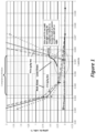
- Figure 1 is a chart illustrating example CO and NOx emissions curves relative to lambda ( ⁇ ).
- lambda is the air-fuel equivalence ratio (actual air-fuel ratio / stoichiometric air-fuel ratio).
- NOx and CO concentrations are not linear, but rather changed dramatically as the "knee" of each of the respective curve representing the concentration of NOx and CO is approached.
- the g/bhp-hr of NOx emitted may increase at a much greater rate as lambda surpasses 0.995 and approaches 0.996, while the g/bhp-hr of CO emitted may increase at a much greater rate as lambda declines below 0994 and retreats towards 0.993.
- This chart also shows the compliance window, or operating window, in which CO and NOx emissions are below desired levels. The range of lambda in this window is dependent on the current NOx and CO emission levels. However, as conditions change in the engine and/or the environment in which the engine is operating, NOx and CO emissions levels for any particular lambda may change, and therefore the operating window may change in size and location relative to lambda.
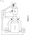
- Figure 2 illustrates exemplary system 200, including engine 210 and catalyst 220, that may be implemented according to an embodiment. Note that the entirely of system 200 may also be referred to as an "engine”.
- System 200 is a simplified block diagram that will be used to explain the concepts disclosed herein, and therefore is not to be construed as setting forth any physical requirements or particular configuration required for any embodiment disclosed herein. All components, devices, systems and methods described herein may be implemented with or take any shape, form, type, or number of components, and any combination of any such components that are capable of implementing the disclosed embodiments. All such embodiments are contemplated as within the scope of the present disclosure.
- Engine 210 may be any type of internal combustion engine or any device, component, or system that includes an internal combustion component that generates exhaust gases.
- engine 210 may be a natural gas fueled internal combustion engine configured to operate with a stoichiometric amount of fuel or a slight excess of fuel in proportion to oxygen (i.e., rich).
- Engine 210 may exhaust gases through exhaust piping 211 into catalyst 220 which then exhausts converted exhaust gases.
- Catalyst 220 represents one or more catalysts of any type, and any combination of any types of catalysts.
- sensors may be used at various points along the exhaust flow to collect data regarding the content of exhaust gases.
- the collected data may be provided to emissions control module 230, which may be any type of device, component, computer, or combination thereof, that may be configured to determine an appropriate air-fuel mixture based on the level of one or more compounds in exhaust gases.
- Emissions control module 230 may, upon determining the optimal air-fuel mixture or an appropriate adjustment in the air-fuel mixture, transmit instructions to or otherwise control air-fuel regulators 241 and 242 so that air-fuel regulators 241 and 242 cause the correct air-fuel mixture to be sent to engine 210.
- Each of air-fuel regulators 241 and 242 may be a fuel system, carburetor, fuel injector, fuel pass regulator, any system including one or more of these, or any combination thereof.
- system 200 may include pre-catalyst sensors, mid-catalyst sensors, and post-catalyst sensors.
- post-catalyst sensor 271 may be an oxygen (e.g., O 2 ) sensor and post-catalyst sensor 272 may be a NOx sensor.
- Post-catalyst sensor 272 may also, or instead, be a CO sensor.
- Post-catalyst sensor 271 may feed data reflecting detected levels of oxygen to emissions control module 230 and post-catalyst sensor 272 may feed data reflecting detected levels of NOx and/or CO to emissions control module 230.
- Post-catalyst sensors 271 and/or 272 may sense overall catalyst efficiency, but may be relatively slow to report changes in the composition of exhaust gases to emissions control module 230 because it senses the gases only after they have been through the entire catalyst system used by engine 210.
- Mid-catalyst sensor 260 may be configured within any one catalyst brick within catalyst 220, or may be any number of sensors configured in any number of catalyst bricks within catalyst 220. Alternatively, mid-catalyst sensor 260 may be configured between two catalyst bricks within catalyst 220, or may configured between two separate catalysts, each of which having one or more catalyst bricks. Note that catalyst 220 represents any number of individual catalysts of any type having any number of catalyst bricks, and mid-catalyst sensor 260 represents any number and type of sensors that may be configured to detect any type of content within a catalyst. All such variations are contemplated as within the scope of the present disclosure.
- Mid-catalyst sensor 260 may be an oxygen (e.g., O 2 ) sensor and may provide an indication of the efficiency of catalyst 220, reporting changes in exhaust gases to emissions control module 230 more rapidly than post-catalyst sensors 271 and 271 as mid-catalyst sensor 260 is configured to detect the level of oxygen at catalyst 220.
- Pre-catalyst sensors 251 and 252 may be oxygen (e.g., O 2 ) sensors and due to their location may react the fastest among the sensors as they will sense and report to emissions control module 230 the content of exhaust gas as it is emitted from engine 210 and before it travels into catalyst 220.
- emissions control module 230 may determine an appropriate air-fuel mixture and transmit data indicating the determined air-fuel mixture or otherwise instruct air-fuel regulators 241 and 242 to operate engine 210 using the determined air-fuel mixture.
- emissions control module 230 may determine an air-fuel mixture set point based on data from pre-catalyst sensors 251 and 252, and then may modify that set point to determine a second set point based on data from mid-catalyst sensor 260. The second set point may then be further modified based on data from post-catalyst sensors 271 and 272.
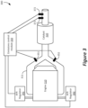
- Figure 3 illustrates exemplary system 300, including engine 310 and catalyst 320, that may be implemented according to an embodiment. Note that the entirely of system 300 may also be referred to as an "engine”.
- System 300 is a simplified block diagram that will be used to explain the concepts disclosed herein, and therefore is not to be construed as setting forth any physical requirements or particular configuration required for any embodiment disclosed herein. All components, devices, systems and methods described herein may be implemented with or take any shape, form, type, or number of components, and any combination of any such components that are capable of implementing the disclosed embodiments. All such embodiments are contemplated as within the scope of the present disclosure.
- Engine 310 may be any type of internal combustion engine or any device, component, or system that includes an internal combustion component that generates exhaust gases.
- engine 310 may be a natural gas fueled internal combustion engine configured to operate with a stoichiometric amount of fuel or a slight excess of fuel in proportion to oxygen (i.e., rich).
- Engine 310 may exhaust gases through exhaust piping 311 into catalyst 320 which then exhausts converted exhaust gases.
- Catalyst 320 represents one or more catalysts of any type, and any combination of any types of catalysts.
- fewer sensors may be used to accomplish the same goals of automating efficient catalyst control.
- Data collected from post-catalyst sensors 371 and 372 and pre-catalyst sensors 351 and 352 may be provided to emissions control module 330, which may be any type of device, component, computer, or combination thereof, that is configured to determine an appropriate air-fuel mixture based on the level of one or more compounds in exhaust gases.
- Emissions control module 330 may, upon determining the optimal air-fuel mixture or an appropriate adjustment in the air-fuel mixture, transmit instructions to or otherwise control air-fuel regulators 341 and 342 so that air-fuel regulators 341 and 342 cause the correct air-fuel mixture to be sent to engine 310.
- air-fuel regulators 341 and3242 may be a fuel system, carburetor, fuel injector, fuel pass regulator, any system including one or more of these, or any combination thereof.
- post-catalyst sensor 371 may be an oxygen (e.g., O 2 ) sensor and post-catalyst sensor 372 may be a NOx sensor.
- Post-catalyst sensor 372 may also, or instead, be a CO sensor.
- Post-catalyst sensor 371 may feed data reflecting detected levels of oxygen to emissions control module 330 and post-catalyst sensor 372 may feed data reflecting detected levels of NOx and/or CO to emissions control module 330.
- Post-catalyst sensors 371 and/or 372 may sense overall catalyst efficiency, but may be relatively slow to report changes in the composition of exhaust gases to emissions control module 330 because it senses the gases only after they have been through the entire catalyst system used by engine 310.
- Pre-catalyst sensors 351 and 352 may be oxygen (e.g., O 2 ) sensors and due to their location may react the fastest among the sensors as they will sense and report to emissions control module 330 the content of exhaust gas as it is emitted from engine 310 and before it travels into catalyst 320.
- oxygen e.g., O 2
- emissions control module 330 may determine an appropriate air-fuel mixture and transmit data indicating the determined air-fuel mixture or otherwise instruct air-fuel regulators 341 and 342 to operate engine 310 using the determined air-fuel mixture.
- emissions control module 330 may determine an air-fuel mixture set point based on data from pre-catalyst sensors 351 and 352, and then may modify that set point to determine a second set point based on data from post-catalyst sensors 371 and 372.
- an initial post-catalyst O 2 set-point level may be determined and loaded into a bias table stored at, or accessible by, emissions control module 330. Based on the bias table, emissions control module 330 may modify the pre-catalyst O 2 air-fuel ratio set-point as the post-catalyst O 2 levels change. In this embodiment, emissions control module 330 may determine the catalyst operating window (an example of which is shown in Figure 1 ) through a sub-routine and set the determined air-fuel ratio set-point as a zero (0) bias point. Emissions control module 330 may then modify the pre-catalyst O 2 set-point as the post-catalyst O 2 level moves.
- the post-catalyst NOx sensor may be used in determining the initial set-point and in modifying the post-catalyst O 2 set-point bias table up and down as NOx levels change.
- emissions control module 330 may be configured with a predetermined emissions compliance level and/or catalyst efficiency.
- preconfigured NOx and/or CO grams level may be set and, upon detection of one or both of these levels being approached, met, and/or exceeded, a user may be notified of the out-of-compliance condition and/or a shutdown of the engine may be performed automatically by emissions control module 330.
- catalyst efficiency may be based on a determined amount of modification of pre-catalyst O 2 setpoints and/or other conditions, such as engine operating hours and load and monitored environmental conditions.
- any system or engine described herein may be operated to achieve an optimum O 2 set-point for NOx and CO compliance.
- one or more NOx sensors as described herein may be used to determine a CO concentration that may be represented as an increase in the NOx parts-per-million (ppm) output as the rich knee of the lambda curve (see Figure 1 ) is approached.
- the increasing CO concentration when an air-fuel mixture is rich may create stable interference in a NOx sensor, where a NOx reading from such a sensor may indicate a higher level of NOx concentration where actually ammonia is being detected.
- a lean air-fuel ratio such a sensor may read similar levels of NOx as normal. Ammonia created at extremely rich air-fuel ratios may be reported as NOx concentration by a NOx sensor.
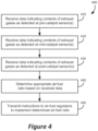
- Figure 4 illustrates exemplary, non-limiting method 400 of implementing an embodiment as disclosed herein.
- Method 400 and the individual actions and functions described in method 400, may be performed by any one or more devices or components, including those described herein, such as the systems illustrated in Figures 1 and 2 .
- method 400 may be performed by any other devices, components, or combinations thereof, in some embodiments in conjunction with other systems, devices and/or components.
- any of the functions and/or actions described in regard to any of the blocks of method 400 may be performed in any order, in isolation, with a subset of other functions and/or actions described in regard to any of the other blocks of method 400 or any other method described herein, and in combination with other functions and/or actions, including those described herein and those not set forth herein. All such embodiments are contemplated as within the scope of the present disclosure.
- data may be received at an emissions control module from one or more pre-catalyst sensors.
- Such sensors may be oxygen (e.g., O 2 ) sensors and/or any other type of sensor.
- data may be received at an emissions control module from one or more mid-catalyst sensors.
- Such sensors may be oxygen (e.g., O 2 ) sensors and/or any other type of sensor.
- data may be received at an emissions control module from one or more post-catalyst sensors.
- Such sensors may be oxygen (e.g., O 2 ) sensors, NOx sensors, CO sensors, and/or any other type of sensor.
- no mid-catalyst sensors may be present, and therefore the functions of block 420 may be omitted. It is contemplated that any number of sensors of any type may be used, and such sensors may be located at any location within an engine and catalyst system.
- an emissions control module may make a determination, based on the data received from one or more sensors, of an appropriate air-fuel ratio. In many embodiments, this determination may be the selection of an air-fuel ratio that maintains or brings the emissions levels of an engine below predetermined levels, such as those mandated by the EPA.
- the emissions control module may instruct or otherwise cause one or more air-fuel regulators to implement the determined air-fuel ratio; i.e., operate the engine using the determined air-fuel ratio.
- the technical effect of the systems and methods set forth herein is the ability to more efficiently control the air-fuel mixture used in an engine, and thereby more efficiently ensure that emissions of the engine are kept at desired levels.
- the use of the disclosed processes and systems may reduce the emissions of such engines to low levels and maintain those emissions at low levels without requiring manual intervention.
- the disclosed systems and methods may be combined with other systems and technologies in order to achieve even greater emissions control and engine performance. All such embodiments are contemplated as within the scope of the present disclosure.
- Figure 5 and the following discussion are intended to provide a brief general description of a suitable computing environment in which the methods and systems disclosed herein and/or portions thereof may be implemented.
- the functions of emissions control modules 230 and 330 may be performed by one or more devices that include some or all of the aspects described in regard to Figure 5 .
- Some or all of the devices described in Figure 5 that may be used to perform functions of the claimed embodiments may be configured in a controller that may be embedded into a system such as those described with regard to Figures 2 and 3 .
- some or all of the devices described in Figure 5 may be included in any device, combination of devices, or any system that performs any aspect of a disclosed embodiment.
- program modules include routines, programs, objects, components, data structures and the like that perform particular tasks or implement particular abstract data types.
- program modules include routines, programs, objects, components, data structures and the like that perform particular tasks or implement particular abstract data types.
- the methods and systems disclosed herein and/or portions thereof may be practiced with other computer system configurations, including hand-held devices, multi-processor systems, microprocessor-based or programmable consumer electronics, network PCs, minicomputers, mainframe computers and the like.
- the methods and systems disclosed herein may also be practiced in distributed computing environments where tasks are performed by remote processing devices that are linked through a communications network.
- program modules may be located in both local and remote memory storage devices.
- FIG. 5 is a block diagram representing a general purpose computer system in which aspects of the methods and systems disclosed herein and/or portions thereof may be incorporated.
- the exemplary general purpose computing system includes computer 520 or the like, including processing unit 521, system memory 522, and system bus 523 that couples various system components including the system memory to processing unit 521.
- System bus 523 may be any of several types of bus structures including a memory bus or memory controller, a peripheral bus, and a local bus using any of a variety of bus architectures.
- the system memory may include read-only memory (ROM) 524 and random access memory (RAM) 525.
- BIOS Basic input/output system 526 (BIOS), which may contain the basic routines that help to transfer information between elements within computer 520, such as during start-up, may be stored in ROM 524.
- Computer 520 may further include hard disk drive 527 for reading from and writing to a hard disk (not shown), magnetic disk drive 528 for reading from or writing to removable magnetic disk 529, and/or optical disk drive 530 for reading from or writing to removable optical disk 531 such as a CD-ROM or other optical media.
- Hard disk drive 527, magnetic disk drive 528, and optical disk drive 530 may be connected to system bus 523 by hard disk drive interface 532, magnetic disk drive interface 533, and optical drive interface 534, respectively.
- the drives and their associated computer-readable media provide non-volatile storage of computer readable instructions, data structures, program modules and other data for computer 520.
- exemplary environment described herein employs a hard disk, removable magnetic disk 529, and removable optical disk 531
- other types of computer readable media that can store data that is accessible by a computer may also be used in the exemplary operating environment.
- Such other types of media include, but are not limited to, a magnetic cassette, a flash memory card, a digital video or versatile disk, a Bernoulli cartridge, a random access memory (RAM), a read-only memory (ROM), and the like.
- a number of program modules may be stored on hard disk drive 527, magnetic disk 529, optical disk 531, ROM 524, and/or RAM 525, including an operating system 535, one or more application programs 536, other program modules 537 and program data 538.
- a user may enter commands and information into the computer 520 through input devices such as a keyboard 540 and pointing device 542.
- Other input devices may include a microphone, joystick, game pad, satellite disk, scanner, or the like.
- serial port interface 546 that is coupled to the system bus, but may be connected by other interfaces, such as a parallel port, game port, or universal serial bus (USB).
- a monitor 547 or other type of display device may also be connected to the system bus 523 via an interface, such as a video adapter 548.
- a computer may include other peripheral output devices (not shown), such as speakers and printers.
- the exemplary system of Figure 5 may also include host adapter 555, Small Computer System Interface (SCSI) bus 556, and external storage device 562 that may be connected to the SCSI bus 556.
- SCSI Small Computer System Interface
- the computer 520 may operate in a networked environment using logical and/or physical connections to one or more remote computers or devices, such as remote computer 549, air-fuel regulators 241, 242, 341, and/or 342.
- Each of air-fuel regulators 241, 242, 341, and/or 342 may be any device as described herein capable of performing the regulation of air and/or fuel entering an engine.
- Remote computer 549 may be a personal computer, a server, a router, a network PC, a peer device or other common network node, and may include many or all of the elements described above relative to the computer 520, although only a memory storage device 550 has been illustrated in Figure 5 .
- the logical connections depicted in Figure 5 may include local area network (LAN) 551 and wide area network (WAN) 552.
- LAN local area network
- WAN wide area network
- computer 520 When used in a LAN networking environment, computer 520 may be connected to LAN 551 through network interface or adapter 553. When used in a WAN networking environment, computer 520 may include modem 554 or other means for establishing communications over wide area network 552, such as the Internet. Modem 554, which may be internal or external, may be connected to system bus 523 via serial port interface 546. In a networked environment, program modules depicted relative to computer 520, or portions thereof, may be stored in a remote memory storage device. It will be appreciated that the network connections shown are exemplary and other means of establishing a communications link between computers may be used.
- Computer 520 may include a variety of computer-readable storage media.
- Computer-readable storage media can be any available tangible media that can be accessed by computer 520 and includes both volatile and nonvolatile media, removable and non-removable media.
- Computer-readable media may comprise computer storage media and communication media.
- Computer storage media include volatile and nonvolatile, removable and non-removable media implemented in any method or technology for storage of information such as computer readable instructions, data structures, program modules or other data.
- Computer storage media include, but are not limited to, RAM, ROM, EEPROM, flash memory or other memory technology, CD-ROM, digital versatile disks (DVD) or other optical disk storage, magnetic cassettes, magnetic tape, magnetic disk storage or other magnetic storage devices, or any other tangible medium which can be used to store the desired information and which can be accessed by computer 520. Combinations of any of the above should also be included within the scope of computer-readable media that may be used to store source code for implementing the methods and systems described herein. Any combination of the features or elements disclosed herein may be used in one or more embodiments.
Landscapes
- Engineering & Computer Science (AREA)
- Chemical & Material Sciences (AREA)
- Combustion & Propulsion (AREA)
- Mechanical Engineering (AREA)
- General Engineering & Computer Science (AREA)
- Health & Medical Sciences (AREA)
- Life Sciences & Earth Sciences (AREA)
- Chemical Kinetics & Catalysis (AREA)
- Physics & Mathematics (AREA)
- Molecular Biology (AREA)
- Analytical Chemistry (AREA)
- Biochemistry (AREA)
- General Health & Medical Sciences (AREA)
- General Physics & Mathematics (AREA)
- Immunology (AREA)
- Pathology (AREA)
- Toxicology (AREA)
- Electrical Control Of Air Or Fuel Supplied To Internal-Combustion Engine (AREA)
- Combined Controls Of Internal Combustion Engines (AREA)
- Exhaust Gas After Treatment (AREA)
Applications Claiming Priority (1)
| Application Number | Priority Date | Filing Date | Title |
|---|---|---|---|
| US13/760,630 US8887490B2 (en) | 2013-02-06 | 2013-02-06 | Rich burn internal combustion engine catalyst control |
Publications (4)
| Publication Number | Publication Date |
|---|---|
| EP2765292A2 EP2765292A2 (en) | 2014-08-13 |
| EP2765292A3 EP2765292A3 (en) | 2018-07-04 |
| EP2765292C0 EP2765292C0 (en) | 2024-11-27 |
| EP2765292B1 true EP2765292B1 (en) | 2024-11-27 |
Family
ID=50068820
Family Applications (1)
| Application Number | Title | Priority Date | Filing Date |
|---|---|---|---|
| EP14153733.2A Active EP2765292B1 (en) | 2013-02-06 | 2014-02-04 | Rich burn internal combustion engine catalyst control |
Country Status (7)
| Country | Link |
|---|---|
| US (1) | US8887490B2 (enExample) |
| EP (1) | EP2765292B1 (enExample) |
| JP (1) | JP2014152777A (enExample) |
| KR (1) | KR20140100437A (enExample) |
| CN (1) | CN103982309A (enExample) |
| BR (1) | BR102014002821B1 (enExample) |
| CA (1) | CA2841288C (enExample) |
Families Citing this family (18)
| Publication number | Priority date | Publication date | Assignee | Title |
|---|---|---|---|---|
| US9399965B2 (en) | 2014-12-12 | 2016-07-26 | General Electric Company | Method and system for control of emissions in exhaust aftertreatment system |
| US10125653B2 (en) | 2015-02-19 | 2018-11-13 | General Electric Company | System and method for engine emission control harness |
| DE102016218794A1 (de) * | 2016-09-29 | 2018-03-29 | Robert Bosch Gmbh | Stationärer Erdgasmotor mit wenigstens einem Stickoxidsensor |
| DE102019205551A1 (de) * | 2019-04-17 | 2020-10-22 | Vitesco Technologies GmbH | Verfahren zum Ermitteln der Sauerstoffbeladung eines Katalysators einer Brennkraftmaschine und Abgasstrang einer Brennkraftmaschine |
| DE102019208254B4 (de) * | 2019-06-06 | 2021-08-26 | Vitesco Technologies GmbH | Verfahren zum Ermitteln des Stickoxidanteils und/oder Ammoniakanteils und Kohlenmonooxidanteils im Abgas einer Brennkraftmaschine und Abgasstrang |
| US11346554B2 (en) * | 2019-09-30 | 2022-05-31 | Rosemount Inc. | Combustion analyzer with simultaneous carbon monoxide and methane measurements |
| US12377711B2 (en) | 2020-08-20 | 2025-08-05 | Denso International America, Inc. | Vehicle feature control systems and methods based on smoking |
| US12251991B2 (en) | 2020-08-20 | 2025-03-18 | Denso International America, Inc. | Humidity control for olfaction sensors |
| US11932080B2 (en) | 2020-08-20 | 2024-03-19 | Denso International America, Inc. | Diagnostic and recirculation control systems and methods |
| US12269315B2 (en) | 2020-08-20 | 2025-04-08 | Denso International America, Inc. | Systems and methods for measuring and managing odor brought into rental vehicles |
| US11881093B2 (en) | 2020-08-20 | 2024-01-23 | Denso International America, Inc. | Systems and methods for identifying smoking in vehicles |
| US11760170B2 (en) | 2020-08-20 | 2023-09-19 | Denso International America, Inc. | Olfaction sensor preservation systems and methods |
| US11636870B2 (en) | 2020-08-20 | 2023-04-25 | Denso International America, Inc. | Smoking cessation systems and methods |
| US11828210B2 (en) | 2020-08-20 | 2023-11-28 | Denso International America, Inc. | Diagnostic systems and methods of vehicles using olfaction |
| US11813926B2 (en) | 2020-08-20 | 2023-11-14 | Denso International America, Inc. | Binding agent and olfaction sensor |
| US12017506B2 (en) | 2020-08-20 | 2024-06-25 | Denso International America, Inc. | Passenger cabin air control systems and methods |
| US11760169B2 (en) | 2020-08-20 | 2023-09-19 | Denso International America, Inc. | Particulate control systems and methods for olfaction sensors |
| CN114352387B (zh) * | 2021-12-27 | 2022-11-29 | 无锡锡创汽车环保有限公司 | 一种寿命更长且能自动更换的汽车尾气净化装置 |
Citations (2)
| Publication number | Priority date | Publication date | Assignee | Title |
|---|---|---|---|---|
| EP0814249B1 (en) * | 1996-06-21 | 2006-10-11 | Ngk Insulators, Ltd. | Method for controlling engine exhaust gas system |
| EP2599985A1 (en) * | 2011-11-30 | 2013-06-05 | Hoerbiger Kompressortechnik Holding GmbH | Air/fuel ratio controller and control method |
Family Cites Families (16)
| Publication number | Priority date | Publication date | Assignee | Title |
|---|---|---|---|---|
| US4492559A (en) | 1983-11-14 | 1985-01-08 | The Babcock & Wilcox Company | System for controlling combustibles and O2 in the flue gases from combustion processes |
| JPS61279749A (ja) * | 1985-06-06 | 1986-12-10 | Nippon Denso Co Ltd | 空燃比制御装置 |
| US5390490A (en) * | 1993-11-04 | 1995-02-21 | Ford Motor Company | Method and apparatus for measuring the efficacy of a catalytic converter |
| JP2869925B2 (ja) * | 1994-06-29 | 1999-03-10 | 本田技研工業株式会社 | 内燃エンジンの空燃比制御装置 |
| JPH0815917A (ja) | 1994-07-01 | 1996-01-19 | Mitsubishi Chem Corp | 静電荷像現像用帯電制御剤 |
| JP3799824B2 (ja) * | 1998-06-26 | 2006-07-19 | 日産自動車株式会社 | 内燃機関の排気浄化装置 |
| JP4265704B2 (ja) * | 1999-04-14 | 2009-05-20 | 本田技研工業株式会社 | 内燃機関の空燃比制御装置及びプラントの制御装置 |
| JP4374518B2 (ja) * | 2001-02-07 | 2009-12-02 | 株式会社デンソー | 内燃機関の排出ガス浄化制御装置 |
| US6546718B2 (en) * | 2001-06-19 | 2003-04-15 | Ford Global Technologies, Inc. | Method and system for reducing vehicle emissions using a sensor downstream of an emission control device |
| DE10332057B4 (de) * | 2003-07-15 | 2006-02-09 | Siemens Ag | Verfahren zur Überprüfung einer Abgasreinigungsanlage |
| US7257943B2 (en) * | 2004-07-27 | 2007-08-21 | Ford Global Technologies, Llc | System for controlling NOx emissions during restarts of hybrid and conventional vehicles |
| JP4835497B2 (ja) * | 2007-04-13 | 2011-12-14 | トヨタ自動車株式会社 | 内燃機関の空燃比制御装置 |
| JP4485553B2 (ja) * | 2007-08-13 | 2010-06-23 | トヨタ自動車株式会社 | NOxセンサの異常診断装置 |
| JP5140138B2 (ja) * | 2010-11-04 | 2013-02-06 | 本田技研工業株式会社 | 制御装置 |
| WO2013049335A2 (en) | 2011-09-28 | 2013-04-04 | Continental Controls Corporation | Automatic set point adjustment system and method for engine air-fuel ratio control system |
| US20130151125A1 (en) | 2011-12-08 | 2013-06-13 | Scott K. Mann | Apparatus and Method for Controlling Emissions in an Internal Combustion Engine |
-
2013
- 2013-02-06 US US13/760,630 patent/US8887490B2/en active Active
-
2014
- 2014-01-30 CA CA2841288A patent/CA2841288C/en active Active
- 2014-01-31 JP JP2014016278A patent/JP2014152777A/ja active Pending
- 2014-02-04 EP EP14153733.2A patent/EP2765292B1/en active Active
- 2014-02-05 KR KR1020140012897A patent/KR20140100437A/ko not_active Ceased
- 2014-02-05 BR BR102014002821-8A patent/BR102014002821B1/pt active IP Right Grant
- 2014-02-07 CN CN201410044952.3A patent/CN103982309A/zh active Pending
Patent Citations (2)
| Publication number | Priority date | Publication date | Assignee | Title |
|---|---|---|---|---|
| EP0814249B1 (en) * | 1996-06-21 | 2006-10-11 | Ngk Insulators, Ltd. | Method for controlling engine exhaust gas system |
| EP2599985A1 (en) * | 2011-11-30 | 2013-06-05 | Hoerbiger Kompressortechnik Holding GmbH | Air/fuel ratio controller and control method |
Also Published As
| Publication number | Publication date |
|---|---|
| CA2841288C (en) | 2020-10-27 |
| BR102014002821B1 (pt) | 2020-11-17 |
| CA2841288A1 (en) | 2014-08-06 |
| EP2765292A2 (en) | 2014-08-13 |
| KR20140100437A (ko) | 2014-08-14 |
| US20140216009A1 (en) | 2014-08-07 |
| CN103982309A (zh) | 2014-08-13 |
| BR102014002821A2 (pt) | 2015-11-24 |
| US8887490B2 (en) | 2014-11-18 |
| EP2765292C0 (en) | 2024-11-27 |
| EP2765292A3 (en) | 2018-07-04 |
| JP2014152777A (ja) | 2014-08-25 |
Similar Documents
| Publication | Publication Date | Title |
|---|---|---|
| EP2765292B1 (en) | Rich burn internal combustion engine catalyst control | |
| US9057301B2 (en) | Emissions control in stationary rich burn engines | |
| US9114363B2 (en) | Aftertreatment system for simultaneous emissions control in stationary rich burn engines | |
| JP6468768B2 (ja) | 触媒失活の監視および空燃比の制御のためのシステムおよび方法 | |
| CN106257023A (zh) | 用于运行内燃机的方法和用于实施该方法的控制装置 | |
| US20130151125A1 (en) | Apparatus and Method for Controlling Emissions in an Internal Combustion Engine | |
| EP3032057B1 (en) | Method and system for control of emissions in exhaust aftertreatment system | |
| US9429088B2 (en) | Lean NOx trap desulfation process | |
| KR102272436B1 (ko) | 암모니아 슬립 촉매 조립체의 유입구에서의 온도 제어를 통해 내연 기관의 배기가스를 제어하기 위한 시스템 및 방법 | |
| Nydegger et al. | The ESG path forward for fracturing equipment making the right technology selection based on field emission results | |
| EP3904663B1 (en) | Excess air coefficient control method and device for catalytic converter, vehicle, and storage medium | |
| US12006856B1 (en) | Aftertreatment for alcohol fuel substituted diesel engines | |
| Toema | Physics-based characterization of lambda sensor output to control emissions from natural gas fueled engines | |
| US11933239B2 (en) | Method, processing unit, and computer program for operating an internal combustion engine having at least one catalytic converter | |
| Jones | Evaluation of Advanced Air-Fuel Ratio Control Strategies and their Effects on Three-Way Catalysts in a Stoichiometric, Spark Ignited, Natural Gas Engine | |
| JP2024175360A (ja) | 排気制御装置及び排気制御方法 | |
| Hohn et al. | Cost-Effective Reciprocating Engine Emissions Control and Monitoring for E&P Field and Gathering Engines | |
| JP2011220134A (ja) | 内燃機関の制御装置 |
Legal Events
| Date | Code | Title | Description |
|---|---|---|---|
| PUAI | Public reference made under article 153(3) epc to a published international application that has entered the european phase |
Free format text: ORIGINAL CODE: 0009012 |
|
| 17P | Request for examination filed |
Effective date: 20140204 |
|
| AK | Designated contracting states |
Kind code of ref document: A2 Designated state(s): AL AT BE BG CH CY CZ DE DK EE ES FI FR GB GR HR HU IE IS IT LI LT LU LV MC MK MT NL NO PL PT RO RS SE SI SK SM TR |
|
| AX | Request for extension of the european patent |
Extension state: BA ME |
|
| PUAL | Search report despatched |
Free format text: ORIGINAL CODE: 0009013 |
|
| AK | Designated contracting states |
Kind code of ref document: A3 Designated state(s): AL AT BE BG CH CY CZ DE DK EE ES FI FR GB GR HR HU IE IS IT LI LT LU LV MC MK MT NL NO PL PT RO RS SE SI SK SM TR |
|
| AX | Request for extension of the european patent |
Extension state: BA ME |
|
| RIC1 | Information provided on ipc code assigned before grant |
Ipc: F01N 3/20 20060101ALI20180525BHEP Ipc: F02D 41/14 20060101AFI20180525BHEP |
|
| STAA | Information on the status of an ep patent application or granted ep patent |
Free format text: STATUS: REQUEST FOR EXAMINATION WAS MADE |
|
| R17P | Request for examination filed (corrected) |
Effective date: 20190104 |
|
| RBV | Designated contracting states (corrected) |
Designated state(s): AL AT BE BG CH CY CZ DE DK EE ES FI FR GB GR HR HU IE IS IT LI LT LU LV MC MK MT NL NO PL PT RO RS SE SI SK SM TR |
|
| RAP1 | Party data changed (applicant data changed or rights of an application transferred) |
Owner name: AI ALPINE US BIDCO INC. |
|
| STAA | Information on the status of an ep patent application or granted ep patent |
Free format text: STATUS: EXAMINATION IS IN PROGRESS |
|
| 17Q | First examination report despatched |
Effective date: 20211220 |
|
| P01 | Opt-out of the competence of the unified patent court (upc) registered |
Effective date: 20230602 |
|
| GRAP | Despatch of communication of intention to grant a patent |
Free format text: ORIGINAL CODE: EPIDOSNIGR1 |
|
| STAA | Information on the status of an ep patent application or granted ep patent |
Free format text: STATUS: GRANT OF PATENT IS INTENDED |
|
| INTG | Intention to grant announced |
Effective date: 20240827 |
|
| GRAS | Grant fee paid |
Free format text: ORIGINAL CODE: EPIDOSNIGR3 |
|
| GRAA | (expected) grant |
Free format text: ORIGINAL CODE: 0009210 |
|
| STAA | Information on the status of an ep patent application or granted ep patent |
Free format text: STATUS: THE PATENT HAS BEEN GRANTED |
|
| AK | Designated contracting states |
Kind code of ref document: B1 Designated state(s): AL AT BE BG CH CY CZ DE DK EE ES FI FR GB GR HR HU IE IS IT LI LT LU LV MC MK MT NL NO PL PT RO RS SE SI SK SM TR |
|
| REG | Reference to a national code |
Ref country code: GB Ref legal event code: FG4D |
|
| REG | Reference to a national code |
Ref country code: CH Ref legal event code: EP |
|
| REG | Reference to a national code |
Ref country code: DE Ref legal event code: R096 Ref document number: 602014091219 Country of ref document: DE |
|
| REG | Reference to a national code |
Ref country code: IE Ref legal event code: FG4D |
|
| U01 | Request for unitary effect filed |
Effective date: 20241210 |
|
| P04 | Withdrawal of opt-out of the competence of the unified patent court (upc) registered |
Free format text: CASE NUMBER: APP_66591/2024 Effective date: 20241216 |
|
| U07 | Unitary effect registered |
Designated state(s): AT BE BG DE DK EE FI FR IT LT LU LV MT NL PT RO SE SI Effective date: 20241219 |
|
| U20 | Renewal fee for the european patent with unitary effect paid |
Year of fee payment: 12 Effective date: 20250121 |
|
| PG25 | Lapsed in a contracting state [announced via postgrant information from national office to epo] |
Ref country code: HR Free format text: LAPSE BECAUSE OF FAILURE TO SUBMIT A TRANSLATION OF THE DESCRIPTION OR TO PAY THE FEE WITHIN THE PRESCRIBED TIME-LIMIT Effective date: 20241127 Ref country code: IS Free format text: LAPSE BECAUSE OF FAILURE TO SUBMIT A TRANSLATION OF THE DESCRIPTION OR TO PAY THE FEE WITHIN THE PRESCRIBED TIME-LIMIT Effective date: 20250327 |
|
| PG25 | Lapsed in a contracting state [announced via postgrant information from national office to epo] |
Ref country code: ES Free format text: LAPSE BECAUSE OF FAILURE TO SUBMIT A TRANSLATION OF THE DESCRIPTION OR TO PAY THE FEE WITHIN THE PRESCRIBED TIME-LIMIT Effective date: 20241127 |
|
| PG25 | Lapsed in a contracting state [announced via postgrant information from national office to epo] |
Ref country code: NO Free format text: LAPSE BECAUSE OF FAILURE TO SUBMIT A TRANSLATION OF THE DESCRIPTION OR TO PAY THE FEE WITHIN THE PRESCRIBED TIME-LIMIT Effective date: 20250227 |
|
| PG25 | Lapsed in a contracting state [announced via postgrant information from national office to epo] |
Ref country code: GR Free format text: LAPSE BECAUSE OF FAILURE TO SUBMIT A TRANSLATION OF THE DESCRIPTION OR TO PAY THE FEE WITHIN THE PRESCRIBED TIME-LIMIT Effective date: 20250228 |
|
| PG25 | Lapsed in a contracting state [announced via postgrant information from national office to epo] |
Ref country code: PL Free format text: LAPSE BECAUSE OF FAILURE TO SUBMIT A TRANSLATION OF THE DESCRIPTION OR TO PAY THE FEE WITHIN THE PRESCRIBED TIME-LIMIT Effective date: 20241127 |
|
| PGFP | Annual fee paid to national office [announced via postgrant information from national office to epo] |
Ref country code: GB Payment date: 20250123 Year of fee payment: 12 |
|
| PG25 | Lapsed in a contracting state [announced via postgrant information from national office to epo] |
Ref country code: RS Free format text: LAPSE BECAUSE OF FAILURE TO SUBMIT A TRANSLATION OF THE DESCRIPTION OR TO PAY THE FEE WITHIN THE PRESCRIBED TIME-LIMIT Effective date: 20250227 |
|
| PG25 | Lapsed in a contracting state [announced via postgrant information from national office to epo] |
Ref country code: SM Free format text: LAPSE BECAUSE OF FAILURE TO SUBMIT A TRANSLATION OF THE DESCRIPTION OR TO PAY THE FEE WITHIN THE PRESCRIBED TIME-LIMIT Effective date: 20241127 |
|
| PG25 | Lapsed in a contracting state [announced via postgrant information from national office to epo] |
Ref country code: SK Free format text: LAPSE BECAUSE OF FAILURE TO SUBMIT A TRANSLATION OF THE DESCRIPTION OR TO PAY THE FEE WITHIN THE PRESCRIBED TIME-LIMIT Effective date: 20241127 |
|
| PG25 | Lapsed in a contracting state [announced via postgrant information from national office to epo] |
Ref country code: CZ Free format text: LAPSE BECAUSE OF FAILURE TO SUBMIT A TRANSLATION OF THE DESCRIPTION OR TO PAY THE FEE WITHIN THE PRESCRIBED TIME-LIMIT Effective date: 20241127 |
|
| PG25 | Lapsed in a contracting state [announced via postgrant information from national office to epo] |
Ref country code: MC Free format text: LAPSE BECAUSE OF FAILURE TO SUBMIT A TRANSLATION OF THE DESCRIPTION OR TO PAY THE FEE WITHIN THE PRESCRIBED TIME-LIMIT Effective date: 20241127 |
|
| REG | Reference to a national code |
Ref country code: CH Ref legal event code: PL |
|
| PLBE | No opposition filed within time limit |
Free format text: ORIGINAL CODE: 0009261 |
|
| STAA | Information on the status of an ep patent application or granted ep patent |
Free format text: STATUS: NO OPPOSITION FILED WITHIN TIME LIMIT |
|
| PG25 | Lapsed in a contracting state [announced via postgrant information from national office to epo] |
Ref country code: CH Free format text: LAPSE BECAUSE OF NON-PAYMENT OF DUE FEES Effective date: 20250228 |
|
| 26N | No opposition filed |
Effective date: 20250828 |