EP2765239B1 - Foreign matter removal device for track branching section - Google Patents
Foreign matter removal device for track branching section Download PDFInfo
- Publication number
- EP2765239B1 EP2765239B1 EP12832037.1A EP12832037A EP2765239B1 EP 2765239 B1 EP2765239 B1 EP 2765239B1 EP 12832037 A EP12832037 A EP 12832037A EP 2765239 B1 EP2765239 B1 EP 2765239B1
- Authority
- EP
- European Patent Office
- Prior art keywords
- rail
- fixing member
- pipe
- stock
- foreign material
- Prior art date
- Legal status (The legal status is an assumption and is not a legal conclusion. Google has not performed a legal analysis and makes no representation as to the accuracy of the status listed.)
- Active
Links
Images





Classifications
-
- E—FIXED CONSTRUCTIONS
- E01—CONSTRUCTION OF ROADS, RAILWAYS, OR BRIDGES
- E01B—PERMANENT WAY; PERMANENT-WAY TOOLS; MACHINES FOR MAKING RAILWAYS OF ALL KINDS
- E01B19/00—Protection of permanent way against development of dust or against the effect of wind, sun, frost, or corrosion; Means to reduce development of noise
-
- B—PERFORMING OPERATIONS; TRANSPORTING
- B08—CLEANING
- B08B—CLEANING IN GENERAL; PREVENTION OF FOULING IN GENERAL
- B08B5/00—Cleaning by methods involving the use of air flow or gas flow
- B08B5/02—Cleaning by the force of jets, e.g. blowing-out cavities
-
- B—PERFORMING OPERATIONS; TRANSPORTING
- B61—RAILWAYS
- B61L—GUIDING RAILWAY TRAFFIC; ENSURING THE SAFETY OF RAILWAY TRAFFIC
- B61L1/00—Devices along the route controlled by interaction with the vehicle or train
- B61L1/20—Safety arrangements for preventing or indicating malfunction of the device, e.g. by leakage current, by lightning
-
- B—PERFORMING OPERATIONS; TRANSPORTING
- B61—RAILWAYS
- B61L—GUIDING RAILWAY TRAFFIC; ENSURING THE SAFETY OF RAILWAY TRAFFIC
- B61L5/00—Local operating mechanisms for points or track-mounted scotch-blocks; Visible or audible signals; Local operating mechanisms for visible or audible signals
- B61L5/02—Mechanical devices for operating points or scotch-blocks, e.g. local manual control
-
- B—PERFORMING OPERATIONS; TRANSPORTING
- B61—RAILWAYS
- B61L—GUIDING RAILWAY TRAFFIC; ENSURING THE SAFETY OF RAILWAY TRAFFIC
- B61L5/00—Local operating mechanisms for points or track-mounted scotch-blocks; Visible or audible signals; Local operating mechanisms for visible or audible signals
- B61L5/10—Locking mechanisms for points; Means for indicating the setting of points
-
- E—FIXED CONSTRUCTIONS
- E01—CONSTRUCTION OF ROADS, RAILWAYS, OR BRIDGES
- E01B—PERMANENT WAY; PERMANENT-WAY TOOLS; MACHINES FOR MAKING RAILWAYS OF ALL KINDS
- E01B7/00—Switches; Crossings
- E01B7/20—Safety means for switches, e.g. switch point protectors, auxiliary or guiding rail members
-
- E—FIXED CONSTRUCTIONS
- E01—CONSTRUCTION OF ROADS, RAILWAYS, OR BRIDGES
- E01H—STREET CLEANING; CLEANING OF PERMANENT WAYS; CLEANING BEACHES; DISPERSING OR PREVENTING FOG IN GENERAL CLEANING STREET OR RAILWAY FURNITURE OR TUNNEL WALLS
- E01H8/00—Removing undesirable matter from the permanent way of railways; Removing undesirable matter from tramway rails
Definitions
- the present invention relates to a foreign material removing device of a track turnout portion.
- Patent Literature 1 discloses a foreign material removing device of a track turnout portion which can supply compressed air supplied from a compressed air source device through a compressed air supply path, to a piping unit through a piping joint portion disposed below a stock rail, and can be easily installed on the stock rail without specially machining the stock rail.
- the foreign material removing device of the track turnout portion disclosed in Patent Literature 1 is a device which has point rails which can move to contact and move away from the stock rails, and removes a foreign material dropped between the stock rail of the track turnout portion to which a rail stopper which regulates an interval between the stock rail and the point rail is fixed to a lateral surface of the stock rail opposed to the point rail, and the point rail, has: the piping unit which is provided to the lateral surface of the stock rail opposed to the point rail; the compressed air source device which is installed near the track turnout portion and is connected to the piping unit through the compressed air supply path; a plurality of nozzle portions which are provided by being arranged in a longitudinal direction of the piping unit, and spray the compressed air from the compressed air source device to a front end side of the point rail; and the piping joint portion which is disposed closer to a back end side of the point rail than the rail stopper and below the stock rail, and connects the piping unit and the compressed air supply path, and has features that the
- Patent Literature 2 describes a foreign matter removing apparatus of a track branching unit, where foreign matter that has fallen between the basic rail and the tongue rail of a railroad track branching unit is removed by air injection.
- the foreign matter removing apparatus when compressed air from a compressed air source device is ejected from nozzles to piping units sides, an air flow to the front end of a tongue rail is generated between the main rail and the tongue rail and lumps of ice or snow or foreign materials dropped between the main rails and the tongue rails are blown out by the air flow and removed.
- Patent Literature 1 Although an effect of the foreign material removing device of the track turnout portion disclosed in Patent Literature 1 can be acknowledged, when the bolt provided in the horizontal direction is tightly fastened, a fixing bracket formed in an L shape in Patent Literature 1 rotates, and there is a problem that a gap is produced between a rail belly portion and the nozzles.
- Patent Literature 2 there is no disclosure or suggestion that fixing member is bent such that the pipe is pressed against the concave portion of the lateral surface of the stock rail opposed to the point rail.
- nozzles for a foreign material removing device of a track turnout portion are applied to a track of a bullet train.
- the nozzles for the foreign material removing device of the track turnout portion can be used not only for tracks for bullet trains but also for other tracks such as of conventional railway lines.
- Figure 1 is a schematic plan view a track turnout portion.
- a pair of stock rails 501 and a pair of point rails 502 are mainly installed on a track turnout portion 800.
- the pair of point rails 502 are provided between the pair of stock rails 501.
- each point rail 502 is provided to be capable of contacting and moving away from each stock rail 501 by a point switching device (not illustrated).
- the point rails 502 move in a direction to contact or move away from the stock rails 501, and an operation (point switching operation) of switching traveling rails of the track turnout portion 800 is performed.
- a railway vehicle which travels on the track turnout portion 800 can travel in one of directions of main rails (not illustrated) and the stock rails 501.
- a foreign material removing device 100 mainly has nozzle devices 101, main pipes 550 and 560, branch pipes 520 and a tank unit 200.
- the main pipe 550 is connected to an air tank 220 of the tank unit 200, and the main pipe 550 connects to the main pipe 560. Further, the main pipes 560 are disposed in parallel to the stock rails 501.
- a plurality of branch pipes 520 are provided to branch from the main pipe 560, and a nozzle device 101 is provided at a front end of the branch pipe 520.
- the branch pipe 520 is provided between one floorboard 610 and the neighboring floorboard 610. That is, there is a space between one floorboard 610 and the neighboring floorboard 610 and below the stock rails 501.
- the nozzle device 101 has a pipe 180 and nozzle portions 110, and is provided to a belly portion of the stock rail 501 (see Figures 3 and 4 ).
- FIG. 2 is a schematic view illustrating a schematic configuration of the tank unit 200.
- the tank unit 200 mainly has a controller 201, a compressor 210, the air tank 220 and an electromagnetic valve 230.
- the controller 201 controls the compressor 210 to drive and controls the electromagnetic valve 230 to open and close.
- the compressor 210 compresses an outside air according to the command of the controller 201, and supplies the outside air to the air tank 220.
- the air tank 220 stores the compressed air.
- the electromagnetic valve 230 performs an opening operation according to a switch command from the controller 201, and supplies the compressed air stored in the air tank 220, to the nozzle device 101 through the main pipes 550 and 560 and the branch pipes 520 (see Figure 1 ).
- the controller 201 outputs a switch command to the electromagnetic valve 230 based on detection results of various sensors such as a sensor (not illustrated) for detecting that snow or foreign materials drop or a snow sensor (not illustrated), operation command signals of various equipment such as an operation signal of a point (a point switch signal) or a signal generated by a timer or the like on a regular basis.
- various sensors such as a sensor (not illustrated) for detecting that snow or foreign materials drop or a snow sensor (not illustrated), operation command signals of various equipment such as an operation signal of a point (a point switch signal) or a signal generated by a timer or the like on a regular basis.
- operation command signals of various equipment such as an operation signal of a point (a point switch signal) or a signal generated by a timer or the like on a regular basis.
- the nozzle device 101 sprays the compressed air to perform an operation of removing foreign materials.
- the air tank is not limited to this, and a plurality of air tanks may be used and, when, for example, the tank unit 200 cannot be arranged near a track such as an elevated track, the electromagnetic valve 230, the controller 201 and only a small air tank may be provided near the track and the compressor 210 or the big air tank 220 may be arranged below the elevated track.
- Figure 3 is a schematic view for explaining the details of the nozzle device 101
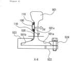
- Figure 4 is an X-X line cross-sectional view of Figure 3
- Figure 5 is a Y-Y line cross-sectional view of Figure 3
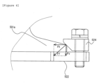
- Figure 6 is a view for explaining an effect of a fixing member in Figure 4 .
- Figure 3(a) illustrates a top view of the nozzle device 101 and Figure 3(b) illustrates a side view of the nozzle device 101.
- the nozzle device 101 mainly has joint portions 521 which are connected with the branch pipes 520, a fixing member 522 which is not connected with the branch pipe 520, the pipe 180 which is a nearly square pipe and a plurality of the nozzle portions 110.
- the joint portions 521 are provided at predetermined intervals of the pipe 180 and, when there is an interval between the joint portion 521 and the neighboring joint portion 521, the fixing member 522 is provided.
- the nozzle portions 110 are arranged at predetermined intervals on the upper and lower surfaces of the pipe 180. Furthermore, although a plurality of the nozzle portions 110 are provided, all the nozzle portions 110 may be formed in the same shape. Still further, the nozzle portions 110 provided on the upper and lower surfaces of the pipe 180 may have attack angles which are alternately different toward the point rails 502 on the upper surface or the lower surface of the pipe 180. For example, one attack angle is in a range of 5 degrees or more to 10 degrees or less, and the other attack angle is in a range of more than 10 degrees to 20 degrees or less.
- the fixing member 522 is provided along a lower surface of leg portions 501a and 501b (lowermost portions) of the stock rail 501, and a fixing member 524 having a tapered surface is provided on the upper surface of the leg portion 501a and is fastened in a vertical direction by a bolt. Further, a fixing portion 523 of the fixing member 522 is provided on the upper surface of the leg portion 501b. The fixing portion 523 supports the pipe 180 by means of the fixing member 525.
- the fixing member 525 is bent such that the pipe 180 at the belly portion 501c of the stock rail 501 is pressed (a force in a direction of an arrow FF) in a direction from the left side to the right side of the stock rail 501 in Figure 4 .
- an angle formed between the pipe 180 and a horizontal portion (horizontal plane) of the fixing member 522 is preferably an acute angle.
- the angle ⁇ is preferably 80 degrees to less than 90 degrees and is more preferably 85 degrees to 89 degrees.
- the fixing member 524 which has a tapered surface is provided on the upper surface of the leg portion 501a and the fixing member 524 is fastened in the vertical direction by the bolt, so that a force Fh in the horizontal direction and a force Fv in the vertical direction (which are F as a resultant force) apply to the leg portion 501a. That is, the force Fv in the vertical direction tightly attaches the bottom surface of the stock rails 501 and the surface of the fixing member 522 opposed to the bottom surface.
- the force Fh in the horizontal direction causes the fixing portion 523 and the fixing member 524 to sandwich the stock rail 501, so that the pipe 180 supported by the fixing member 525 fixed by being sandwiched by the fixing member 523 and the leg portion 501b tightly attaches to the stock rail 501.
- the fixing member is fastened by a bolt from above in the vertical direction instead of being fastened by a bolt in the horizontal direction, so that operability is good and the fixing member is easily fixed.
- a hollow joint portion 521 in which compressed air circulates is provided along the lower surface of the leg portions 501a and 501b (lowermost portions) of the stock rail 501. That is, the joint portion 521 is provided from a side of the stock rail 501 which does not oppose the point rail 502 to a side of the stock rail 501 which opposes to the point rail 502 and along the lower surface of the stock rail 501.
- the joint portion 521 extends to the belly portion 501c (center concave portion) of the stock rail 501, and is provided with the pipe 180 at a front end. Meanwhile, a bent portion 530 which is provided halfway to the joint portion 521 is disposed at a position along the stock rail 501 such that the bent portion 530 does not interfere with the point rail 502 even when the point rail 502 comes the closest to the stock rail 501, and also has the thickness which does not interfere with the point rail 502.
- bent portion 530 is bent such that the pipe 180 at the belly portion 501c of the stock rail 501 is applied a force (a force in a direction of an arrow FF) to be pressed from the point rail 502 side to a direction opposite to the point rail 502.
- an angle formed between the pipe 180 and a horizontal portion (horizontal plane) of the joint portion 521 is preferably an acute angle.
- the angle ⁇ is preferably 85 degrees to less than 90 degrees and is more preferably 85 degrees to 89 degrees.
- elastic deformation of the bent portion 530 can cause the pipe 180 to produce the force of the arrow FF at the belly portion 501c of the stock rail 501 at all times.
- the force of the arrow FF is such a force that a problem that the position of the pipe 180 is shifted when compressed air is sprayed and the like does not occur.
- the fixing member 524 described with reference to Figures 4 and 6 is provided, and a flange portion 521F of the joint portion 521 is further fixed to the joint portion 521 in the front-back direction (the vertical direction in the figure) of the stock rail 501.
- the fixing member 524 can be fastened to the flange portion 521F of the joint portion 521 from above in the vertical direction, so that it is possible to reliably hold the pipes 180 and the like without performing special machining such as machining to open holes in the stock rails 501 similarly as described above.
- the fixing member is fastened by a bolt from above in the vertical direction instead of being fastened by a bolt in the horizontal direction, so that operability is good and the fixing member is easily fixed.
- the flange portion 521F is provided to include a position to contact the lower surface of the leg portion 501a (lowermost portion) of the stock rail 501, and the force Fv in the vertical direction does not directly apply to the joint portion 521 which is a hollow member, so that the joint portion 521 is not deflected and can be more tightly attached.
- the nozzle portion 110 is formed with a cylindrical body and a holding portion which holds the cylindrical body.
- the nozzle portion 110 is held by the holding potion such that the cylindrical body is directed in the substantially same direction as an extension direction of the pipe 180, and is formed in an L shape.
- the cylindrical body has an inclined portion, and the inclined portion is arranged by being directed toward the point rail 502. As a result, it is possible to widen a spray angle from the nozzle portion 110 with respect to the horizontal plane.
- a plurality of rectangular slits are disposed in a radial pattern from a center of a virtual circle in a top panel of the cylindrical body.
- the slits are formed as rectangular columnar holes without providing orifice portions like general nozzles, so that it is possible to reduce noise.
- the nozzle portion 110 has a shape which prevents noise in the present embodiment, the nozzle portion 110 is not limited to this and other arbitrary nozzle portions may be used.
- the pipes 180 and the nozzle portions 110 are arranged in close contact with the lateral surface sides of the stock rails 501 opposed to the point rails 502, by the bent portions 530 of the joint portions 521.
- the bent portion 530 or the fixing member 525 elastically deforms with respect to the belly portion 501c of the lateral surface of the stock rail 501 such that the bent portion 530 of the joint portion 521 or the fixing member 525 causes the pipe 180 and the nozzle portion 110 to press against the belly portion 501c of the lateral surface of the stock rail 501 (pressed by the force in the direction of the arrow FF). Consequently, it is possible to reliably arrange the pipes 180 at positions at which the pipes 180 do not interfere with the point rails 502 during construction without performing special machining such as machining to open holes in rails themselves, and prevent the pipes 180 and the nozzle portions 110 from being displaced toward the point rails 502 even when compressed air is sprayed.
- the nozzles are tightly attached and fixed stably to the stock rails 501 in this way, so that it is possible to reliably prevent the pipes 180 and the nozzle portions 110 from interfering with the point rails 502. As a result, it is possible to reliably prevent the pipes 180 and the nozzle portions 110 from being damaged and reliably remove foreign materials between the stock rails 501 and the point rails 502.
- the fixing members 524 having the tapered surfaces are fastened by bolts in the vertical direction, so that it is possible to disperse the force Fh in the horizontal direction and the force Fv in the vertical direction in the leg portions 501a of the stock rails 501 and reliably tightly attach and fix the nozzle devices 101 or the pipes 180 to the stock rails 501.
- Figure 7 is a schematic view for explaining details of a nozzle device 101a according to the second embodiment
- Figure 8 is an X1-X1 line cross-sectional view of Figure 7
- Figure 9 is a Y1-Y1 line cross-sectional view of Figure 7 .
- Figure 7(a) illustrates a top view of the nozzle device 101a
- Figure 7(b) illustrates a side view of the nozzle device 101a.
- the nozzle device 101a mainly has a joint portion 521a which is connected with a branch pipe 520, fixing members 522a which are not connected with the branch pipe 520, a pipe 180a which is a nearly square pipe and a plurality of nozzle portions 110a.
- the joint portion 521a is provided at one position, and the fixing members 522a are provided on both sides of the joint portion 521a.
- a length L of the pipe 180a is in the range of about 0.5 m to 1.5 m. Furthermore, the length L of the pipe 180a is more preferably 1 m.
- the nozzle portions 110a are arranged at predetermined intervals in the upper and lower surfaces of the pipe 180a.
- a solid fixing member 522a is provided along a lower surface of leg portions 501a and 501b (lowermost portions) of a stock rail 501, and a fixing member 524 having a tapered surface is provided on the upper surface of the leg portion 501a and is fastened in a vertical direction by a bolt. Further, a solid fixing member 523a welded to the fixing member 522a is provided in the vertical direction in the upper surface of the leg portion 501b. Furthermore, one end of a solid fixing member 525a which has a bent portion along the stock rail 501 is welded to the fixing member 523a. The pipe 180a is supported at the other end of the fixing member 525a.
- the fixing member 525a has a bent portion formed such that the pipe 180a at a belly portion 501c of the stock rail 501 is pressed (a force in a direction of an arrow FF) in a direction from the left side to the right side of the stock rail 501 in Figure 8 .
- an angle formed between the pipe 180a and a horizontal portion (horizontal plane) of the fixing member 522a is preferably an acute angle.
- the angle ⁇ is preferably 85 degrees to less than 90 degrees and is more preferably 85 degrees to 89 degrees.
- a hollow joint portion 521a in which compressed air circulates is provided along the lower surface of the leg portions 501a and 501b (lowermost portions) of the stock rail 501. That is, the joint portion 521a is provided from a side of the stock rail 501 which does not oppose the point rail 502 to a side of the stock rail 501 which opposes to the point rail 502 and along the lower surface of the stock rail 501.
- the joint portion 521a extends to the belly portion 501c (center concave portion) of the stock rail 501, and is provided with the pipe 180a at a front end. Meanwhile, a bent portion 530a which is provided halfway to the joint portion 521a is provided at a position along the stock rail 501 such that the bent portion 530a does not interfere with the point rail 502 even when the point rail 502 comes the closest to the stock rail 501, and also has the thickness which does not interfere with the point rail 502.
- the bent portion 530a is formed such that the pipe 180a at the belly portion 501c of the stock rail 501 does not apply the force FF to the point rail 502.
- Figure 10 is a schematic cross-sectional view illustrating another example of a joint portion 521a in Figure 9 .
- "b" will be mainly added to the ends of reference numerals for the description and the reference numerals of the same numerical values will mean the substantially same functions and structures.
- a joint portion 521b has slide mechanisms 540b and 541b.
- the slide mechanism 540b is provided at one end side of a bent portion 530, and is slidably provided in a direction of an arrow HS1 which is a horizontal direction.
- the slide mechanism 541b is provided at the other end side of the bent portion 530, and is slidably provided in a direction of an arrow VS1 which is a vertical direction.
- the slide mechanisms 540b and 541b can absorb vibration, so that it is possible to prevent damages, cracks, failure or the like of the nozzle devices 101b.
- the nozzle devices 101a and 101b of the foreign material removing devices 100a and 100b according to the second embodiment have a length of about 1 m, so that it is possible to improve attachment operability. Further, attaching the nozzle devices by avoiding other devices which are originally provided to the stock rails 501 also becomes easy.
- the fixing members 522a, 523a and 525a press the piping units 180a against concave portions 501c of lateral surfaces of the stock rails 501 to fix.
- the joint portion 521a which is provided separately from the fixing members 522a, 523a and 525a supplies compressed air to the piping unit 180a. Consequently, the piping unit 180a is not fixed by the joint portion 521a which is a hollow member which supplies compressed air to the piping unit 180a, so that it is possible to fix the piping unit 180a fast to the stock rail 501.
- the joint portion 521b illustrated in Figure 10 has the slide mechanisms 540b and 541b, so that, even when vibration caused when a vehicle passes displaces the stock rails 501, it is possible to absorb the displacement by the slide mechanisms 540b and 541b and supply compressed air. As a result, it is possible to prevent failure, damages, cracks or the like of the foreign material removing device 100b caused by the displacement.
- the nozzle devices 101, 101a and 101b correspond to a piping unit
- the stock rails 501 correspond to stock rails
- the foreign material removing devices 100, 100a and 100b correspond to a foreign material removing device of a track turnout portion
- the point rails 502 correspond to point rails
- the bent portion 530 or the fixing member 525a of the joint portion 521 corresponds to a close-contact arrangement structure
- the angle ⁇ corresponds to an acute angle
- the fixing members 522a, 523a and 525a correspond to a fixing portion
- the fixing member 524 corresponds to a member which has a tapered surface.
Landscapes
- Engineering & Computer Science (AREA)
- Mechanical Engineering (AREA)
- Architecture (AREA)
- Civil Engineering (AREA)
- Structural Engineering (AREA)
- Automation & Control Theory (AREA)
- Railway Tracks (AREA)
- Cleaning Of Streets, Tracks, Or Beaches (AREA)
- Cleaning In General (AREA)
- Train Traffic Observation, Control, And Security (AREA)
- Nozzles (AREA)
Description
- The present invention relates to a foreign material removing device of a track turnout portion.
- Conventionally, dropped snow or ice which drops due to vibration caused when a vehicle passes a track turnout portion, rocks thrown when dropped snow or ice drops on ballasts and the ballasts jump, or the like, are sandwiched between a stock rail of the track turnout portion and a point rail, and there is a problem that the point rails are not shifted. Hence, various foreign material removing devices of track turnout portions have been developed or researched.
- For example, Patent Literature 1 discloses a foreign material removing device of a track turnout portion which can supply compressed air supplied from a compressed air source device through a compressed air supply path, to a piping unit through a piping joint portion disposed below a stock rail, and can be easily installed on the stock rail without specially machining the stock rail.
- The foreign material removing device of the track turnout portion disclosed in Patent Literature 1 is a device which has point rails which can move to contact and move away from the stock rails, and removes a foreign material dropped between the stock rail of the track turnout portion to which a rail stopper which regulates an interval between the stock rail and the point rail is fixed to a lateral surface of the stock rail opposed to the point rail, and the point rail, has: the piping unit which is provided to the lateral surface of the stock rail opposed to the point rail; the compressed air source device which is installed near the track turnout portion and is connected to the piping unit through the compressed air supply path; a plurality of nozzle portions which are provided by being arranged in a longitudinal direction of the piping unit, and spray the compressed air from the compressed air source device to a front end side of the point rail; and the piping joint portion which is disposed closer to a back end side of the point rail than the rail stopper and below the stock rail, and connects the piping unit and the compressed air supply path, and has features that the rail stopper is screwed to the stock rail by an attaching bolt which penetrates the stock rail in the horizontal direction, and the piping unit is screwed to the stock rail together with the rail stopper by the attaching bolt.
-
- [Patent Literature 1]
Japanese Patent Laid-Open No. 2000-144602 - [Patent Literature 2]
Japanese Patent Laid-Open No. H07-54317 - Patent Literature 2 describes a foreign matter removing apparatus of a track branching unit, where foreign matter that has fallen between the basic rail and the tongue rail of a railroad track branching unit is removed by air injection. In the foreign matter removing apparatus, when compressed air from a compressed air source device is ejected from nozzles to piping units sides, an air flow to the front end of a tongue rail is generated between the main rail and the tongue rail and lumps of ice or snow or foreign materials dropped between the main rails and the tongue rails are blown out by the air flow and removed.
- Although an effect of the foreign material removing device of the track turnout portion disclosed in Patent Literature 1 can be acknowledged, when the bolt provided in the horizontal direction is tightly fastened, a fixing bracket formed in an L shape in Patent Literature 1 rotates, and there is a problem that a gap is produced between a rail belly portion and the nozzles.
- Also, in Patent Literature 2, there is no disclosure or suggestion that fixing member is bent such that the pipe is pressed against the concave portion of the lateral surface of the stock rail opposed to the point rail.
- It is therefore an object of the present invention to provide a foreign material removing device of a track turnout portion which can tightly attach and fix nozzles stably to a rail belly portion without machining a rail itself.
- The above and other problems are solved by a foreign material removing device as defined in the independent claim. Preferred embodiments are set forth in the dependent claims.
-
- [
Figure 1] Figure 1 is a schematic plan view illustrating an example of a configuration of a track turnout portion with parts of a foreign material removing device according to the invention. - [
Figure 2] Figure 2 is a schematic view illustrating a schematic configuration of a tank unit, suitable to be used in combination with the foreign material removing device according to the invention. - [
Figure 3] Figure 3 is a schematic view for explaining details of a nozzle device, which can be part of the foreign material removing device according to the invention. - [
Figure 4] Figure 4 is an X-X line cross-sectional view ofFigure 3 , which shows the fixing means of the foreign material removing device according to the invention. - [
Figure 5] Figure 5 is a Y-Y line cross-sectional view ofFigure 3 , which shows fixing means of a foreign material removing device, which is not in accordance with the invention. - [
Figure 6] Figure 6 is a view for explaining an effect of a fixing member inFigure 4 . - [
Figure 7] Figure 7 is a schematic view for explaining details of a nozzle device according to the second embodiment, which is not in accordance with the invention. - [
Figure 8] Figure 8 is an X1-X1 line cross-sectional view ofFigure 7 . - [
Figure 9] Figure 9 is a Y1-Y1 line cross-sectional view ofFigure 7 . - [
Figure 10] Figure 10 is a cross-sectional view illustrating another example ofFigure 9 . -
- 100
- FOREIGN MATERIAL REMOVING DEVICE
- 110
- NOZZLE PORTION
- 180
- PIPE
- 501
- STOCK RAIL
- 502
- POINT RAIL
- 521
- JOINT PORTION
- 524
- FIXING MEMBER
- 530
- BENT PORTION
- 800
- TRACK TURNOUT PORTION
- Hereinafter, an embodiment of the present invention will be described using the figures. A state where nozzles for a foreign material removing device of a track turnout portion is applied to a track of a bullet train will be described in the present embodiment. In addition, the nozzles for the foreign material removing device of the track turnout portion can be used not only for tracks for bullet trains but also for other tracks such as of conventional railway lines.
- First,
Figure 1 is a schematic plan view a track turnout portion. - As illustrated in
Figure 1 , a pair ofstock rails 501 and a pair ofpoint rails 502 are mainly installed on atrack turnout portion 800. As illustrated inFigure 1 , the pair ofpoint rails 502 are provided between the pair ofstock rails 501. - In addition, the
stock rails 501 of thetrack turnout portion 800 illustrated inFigure 1 are disposed on sleepers. Further, thepoint rails 502 are arranged onfloorboards 610 which include bearings arranged on the sleepers, and are movably configured. By this means, eachpoint rail 502 is provided to be capable of contacting and moving away from eachstock rail 501 by a point switching device (not illustrated). - Generally, when points (not illustrated) actuate based on a command from a control device (not illustrated), the
point rails 502 move in a direction to contact or move away from thestock rails 501, and an operation (point switching operation) of switching traveling rails of thetrack turnout portion 800 is performed. As a result, a railway vehicle which travels on thetrack turnout portion 800 can travel in one of directions of main rails (not illustrated) and thestock rails 501. - A foreign
material removing device 100 mainly hasnozzle devices 101,main pipes branch pipes 520 and atank unit 200. - As illustrated in
Figure 1 , themain pipe 550 is connected to anair tank 220 of thetank unit 200, and themain pipe 550 connects to themain pipe 560. Further, themain pipes 560 are disposed in parallel to the stock rails 501. - A plurality of
branch pipes 520 are provided to branch from themain pipe 560, and anozzle device 101 is provided at a front end of thebranch pipe 520. Thebranch pipe 520 is provided between onefloorboard 610 and the neighboringfloorboard 610. That is, there is a space between onefloorboard 610 and the neighboringfloorboard 610 and below the stock rails 501. - In addition, as described below, the
nozzle device 101 has apipe 180 andnozzle portions 110, and is provided to a belly portion of the stock rail 501 (seeFigures 3 and4 ). -
Figure 2 is a schematic view illustrating a schematic configuration of thetank unit 200. As illustrated inFigure 2 , thetank unit 200 mainly has acontroller 201, acompressor 210, theair tank 220 and anelectromagnetic valve 230. - The
controller 201 controls thecompressor 210 to drive and controls theelectromagnetic valve 230 to open and close. Thecompressor 210 compresses an outside air according to the command of thecontroller 201, and supplies the outside air to theair tank 220. Theair tank 220 stores the compressed air. Theelectromagnetic valve 230 performs an opening operation according to a switch command from thecontroller 201, and supplies the compressed air stored in theair tank 220, to thenozzle device 101 through themain pipes Figure 1 ). - More specifically, for example, the
controller 201 outputs a switch command to theelectromagnetic valve 230 based on detection results of various sensors such as a sensor (not illustrated) for detecting that snow or foreign materials drop or a snow sensor (not illustrated), operation command signals of various equipment such as an operation signal of a point (a point switch signal) or a signal generated by a timer or the like on a regular basis. As a result, thenozzle device 101 sprays the compressed air to perform an operation of removing foreign materials. - In addition, although an example where one
air tank 220 is used has been described with reference toFigure 2 , the air tank is not limited to this, and a plurality of air tanks may be used and, when, for example, thetank unit 200 cannot be arranged near a track such as an elevated track, theelectromagnetic valve 230, thecontroller 201 and only a small air tank may be provided near the track and thecompressor 210 or thebig air tank 220 may be arranged below the elevated track. -
Figure 3 is a schematic view for explaining the details of thenozzle device 101,Figure 4 is an X-X line cross-sectional view ofFigure 3 ,Figure 5 is a Y-Y line cross-sectional view ofFigure 3 andFigure 6 is a view for explaining an effect of a fixing member inFigure 4 . -
Figure 3(a) illustrates a top view of thenozzle device 101 andFigure 3(b) illustrates a side view of thenozzle device 101. - As illustrated in
Figure 3 , thenozzle device 101 mainly hasjoint portions 521 which are connected with thebranch pipes 520, a fixingmember 522 which is not connected with thebranch pipe 520, thepipe 180 which is a nearly square pipe and a plurality of thenozzle portions 110. - The
joint portions 521 are provided at predetermined intervals of thepipe 180 and, when there is an interval between thejoint portion 521 and the neighboringjoint portion 521, the fixingmember 522 is provided. - Further, the
nozzle portions 110 are arranged at predetermined intervals on the upper and lower surfaces of thepipe 180. Furthermore, although a plurality of thenozzle portions 110 are provided, all thenozzle portions 110 may be formed in the same shape. Still further, thenozzle portions 110 provided on the upper and lower surfaces of thepipe 180 may have attack angles which are alternately different toward the point rails 502 on the upper surface or the lower surface of thepipe 180. For example, one attack angle is in a range of 5 degrees or more to 10 degrees or less, and the other attack angle is in a range of more than 10 degrees to 20 degrees or less. - Next, as illustrated in
Figure 4 , the fixingmember 522 is provided along a lower surface ofleg portions stock rail 501, and a fixingmember 524 having a tapered surface is provided on the upper surface of theleg portion 501a and is fastened in a vertical direction by a bolt. Further, a fixingportion 523 of the fixingmember 522 is provided on the upper surface of theleg portion 501b. The fixingportion 523 supports thepipe 180 by means of the fixingmember 525. In addition, the fixingmember 525 is bent such that thepipe 180 at thebelly portion 501c of thestock rail 501 is pressed (a force in a direction of an arrow FF) in a direction from the left side to the right side of thestock rail 501 inFigure 4 . - More specifically, as illustrated in
Figure 4 , an angle formed between thepipe 180 and a horizontal portion (horizontal plane) of the fixingmember 522, that is, an angle θ, is preferably an acute angle. For example, the angle θ is preferably 80 degrees to less than 90 degrees and is more preferably 85 degrees to 89 degrees. By this means, elastic deformation of the fixingmember 525 produces the force of the arrow FF at thebelly portion 501c of thestock rail 501 at all times. In addition, the force of the arrow FF is such a force that a problem that the position of thepipe 180 is shifted when compressed air is sprayed or the like does not occur. - As a result, it is possible to prevent the
pipes 180 and thenozzle portions 110 from moving toward the point rails 502, and prevent thepipes 180 and a plurality of thenozzle portions 110 from interfering with the point rails 502 even when the point rails 502 come the closest to the stock rails 501. - As illustrated in
Figure 6 , the fixingmember 524 which has a tapered surface is provided on the upper surface of theleg portion 501a and the fixingmember 524 is fastened in the vertical direction by the bolt, so that a force Fh in the horizontal direction and a force Fv in the vertical direction (which are F as a resultant force) apply to theleg portion 501a. That is, the force Fv in the vertical direction tightly attaches the bottom surface of the stock rails 501 and the surface of the fixingmember 522 opposed to the bottom surface. Further, the force Fh in the horizontal direction causes the fixingportion 523 and the fixingmember 524 to sandwich thestock rail 501, so that thepipe 180 supported by the fixingmember 525 fixed by being sandwiched by the fixingmember 523 and theleg portion 501b tightly attaches to thestock rail 501. As a result, it is possible to reliably hold thepipes 180 and the like without performing special machining such as machining to open holes in the stock rails 501. Further, the fixing member is fastened by a bolt from above in the vertical direction instead of being fastened by a bolt in the horizontal direction, so that operability is good and the fixing member is easily fixed. - Next, as illustrated in
Figure 5 which is an example not in accordance with the invention, in a Y-Y cross section, a hollowjoint portion 521 in which compressed air circulates is provided along the lower surface of theleg portions stock rail 501. That is, thejoint portion 521 is provided from a side of thestock rail 501 which does not oppose thepoint rail 502 to a side of thestock rail 501 which opposes to thepoint rail 502 and along the lower surface of thestock rail 501. - Further, the
joint portion 521 extends to thebelly portion 501c (center concave portion) of thestock rail 501, and is provided with thepipe 180 at a front end. Meanwhile, abent portion 530 which is provided halfway to thejoint portion 521 is disposed at a position along thestock rail 501 such that thebent portion 530 does not interfere with thepoint rail 502 even when thepoint rail 502 comes the closest to thestock rail 501, and also has the thickness which does not interfere with thepoint rail 502. - Further, the
bent portion 530 is bent such that thepipe 180 at thebelly portion 501c of thestock rail 501 is applied a force (a force in a direction of an arrow FF) to be pressed from thepoint rail 502 side to a direction opposite to thepoint rail 502. - More specifically, as illustrated in
Figure 5 , an angle formed between thepipe 180 and a horizontal portion (horizontal plane) of thejoint portion 521, that is, the angle θ, is preferably an acute angle. For example, the angle θ is preferably 85 degrees to less than 90 degrees and is more preferably 85 degrees to 89 degrees. By this means, elastic deformation of thebent portion 530 can cause thepipe 180 to produce the force of the arrow FF at thebelly portion 501c of thestock rail 501 at all times. In addition, the force of the arrow FF is such a force that a problem that the position of thepipe 180 is shifted when compressed air is sprayed and the like does not occur. - As a result, it is possible to prevent the
pipes 180 and thenozzle portions 110 from moving toward the point rails 502, and prevent thepipes 180 and a plurality of thenozzle portions 110 from interfering with the point rails 502 even when the point rails 502 come the closest to the stock rails 501. - Further, in case of
Figure 5 , the fixingmember 524 described with reference toFigures 4 and6 is provided, and aflange portion 521F of thejoint portion 521 is further fixed to thejoint portion 521 in the front-back direction (the vertical direction in the figure) of thestock rail 501. Furthermore, the fixingmember 524 can be fastened to theflange portion 521F of thejoint portion 521 from above in the vertical direction, so that it is possible to reliably hold thepipes 180 and the like without performing special machining such as machining to open holes in the stock rails 501 similarly as described above. Still further, the fixing member is fastened by a bolt from above in the vertical direction instead of being fastened by a bolt in the horizontal direction, so that operability is good and the fixing member is easily fixed. - Moreover, the
flange portion 521F is provided to include a position to contact the lower surface of theleg portion 501a (lowermost portion) of thestock rail 501, and the force Fv in the vertical direction does not directly apply to thejoint portion 521 which is a hollow member, so that thejoint portion 521 is not deflected and can be more tightly attached. - As illustrated in
Figure 3 , thenozzle portion 110 is formed with a cylindrical body and a holding portion which holds the cylindrical body. Thenozzle portion 110 is held by the holding potion such that the cylindrical body is directed in the substantially same direction as an extension direction of thepipe 180, and is formed in an L shape. Further, the cylindrical body has an inclined portion, and the inclined portion is arranged by being directed toward thepoint rail 502. As a result, it is possible to widen a spray angle from thenozzle portion 110 with respect to the horizontal plane. - Further, a plurality of rectangular slits are disposed in a radial pattern from a center of a virtual circle in a top panel of the cylindrical body. As a result, the slits are formed as rectangular columnar holes without providing orifice portions like general nozzles, so that it is possible to reduce noise.
- In addition, although the
nozzle portion 110 has a shape which prevents noise in the present embodiment, thenozzle portion 110 is not limited to this and other arbitrary nozzle portions may be used. - As described above, in the foreign
material removing device 100 of thetrack turnout portion 800 according to the present invention, thepipes 180 and thenozzle portions 110 are arranged in close contact with the lateral surface sides of the stock rails 501 opposed to the point rails 502, by thebent portions 530 of thejoint portions 521. - That is, in this structure, the
bent portion 530 or the fixingmember 525 elastically deforms with respect to thebelly portion 501c of the lateral surface of thestock rail 501 such that thebent portion 530 of thejoint portion 521 or the fixingmember 525 causes thepipe 180 and thenozzle portion 110 to press against thebelly portion 501c of the lateral surface of the stock rail 501 (pressed by the force in the direction of the arrow FF). Consequently, it is possible to reliably arrange thepipes 180 at positions at which thepipes 180 do not interfere with the point rails 502 during construction without performing special machining such as machining to open holes in rails themselves, and prevent thepipes 180 and thenozzle portions 110 from being displaced toward the point rails 502 even when compressed air is sprayed. The nozzles are tightly attached and fixed stably to the stock rails 501 in this way, so that it is possible to reliably prevent thepipes 180 and thenozzle portions 110 from interfering with the point rails 502. As a result, it is possible to reliably prevent thepipes 180 and thenozzle portions 110 from being damaged and reliably remove foreign materials between the stock rails 501 and the point rails 502. - Further, the fixing
members 524 having the tapered surfaces are fastened by bolts in the vertical direction, so that it is possible to disperse the force Fh in the horizontal direction and the force Fv in the vertical direction in theleg portions 501a of the stock rails 501 and reliably tightly attach and fix thenozzle devices 101 or thepipes 180 to the stock rails 501. - Next, a second example, not in accordance with the present invention will be described. Differences of a foreign material removing device 100a of a
track turnout portion 800 according to the second embodiment from the foreignmaterial removing device 100 of thetrack turnout portion 800 according to the first embodiment will mainly be described. -
Figure 7 is a schematic view for explaining details of anozzle device 101a according to the second embodiment,Figure 8 is an X1-X1 line cross-sectional view ofFigure 7 , andFigure 9 is a Y1-Y1 line cross-sectional view ofFigure 7 . -
Figure 7(a) illustrates a top view of thenozzle device 101a, andFigure 7(b) illustrates a side view of thenozzle device 101a. - As illustrated in
Figure 7 , thenozzle device 101a mainly has ajoint portion 521a which is connected with abranch pipe 520, fixingmembers 522a which are not connected with thebranch pipe 520, apipe 180a which is a nearly square pipe and a plurality ofnozzle portions 110a. - As illustrated in
Figure 7 , unlike thenozzle device 101 disclosed in the first embodiment, in thenozzle device 101a, thejoint portion 521a is provided at one position, and the fixingmembers 522a are provided on both sides of thejoint portion 521a. - Further, as illustrated in
Figure 7 , a length L of thepipe 180a is in the range of about 0.5 m to 1.5 m. Furthermore, the length L of thepipe 180a is more preferably 1 m. - Still further, similar to the
nozzle device 101, thenozzle portions 110a are arranged at predetermined intervals in the upper and lower surfaces of thepipe 180a. - Next, as illustrated in
Figure 8 , asolid fixing member 522a is provided along a lower surface ofleg portions stock rail 501, and a fixingmember 524 having a tapered surface is provided on the upper surface of theleg portion 501a and is fastened in a vertical direction by a bolt. Further, asolid fixing member 523a welded to the fixingmember 522a is provided in the vertical direction in the upper surface of theleg portion 501b. Furthermore, one end of asolid fixing member 525a which has a bent portion along thestock rail 501 is welded to the fixingmember 523a. Thepipe 180a is supported at the other end of the fixingmember 525a. - In addition, in the second embodiment, the fixing
member 525a has a bent portion formed such that thepipe 180a at abelly portion 501c of thestock rail 501 is pressed (a force in a direction of an arrow FF) in a direction from the left side to the right side of thestock rail 501 inFigure 8 . - More specifically, as illustrated in
Figure 8 , an angle formed between thepipe 180a and a horizontal portion (horizontal plane) of the fixingmember 522a, that is, an angle θ, is preferably an acute angle. For example, the angle θ is preferably 85 degrees to less than 90 degrees and is more preferably 85 degrees to 89 degrees. By this means, elastic deformation of the fixingmember 525a causes thepipe 180a to produce the force of the arrow FF at thebelly portion 501c of thestock rail 501 at all times. In addition, the force of the arrow FF is such a force that a problem that the position of thepipe 180a is shifted when compressed air is sprayed or the like does not occur. - As a result, it is possible to prevent the
pipes 180a and thenozzle portions 110a from moving toward the point rails 502, and prevent thepipes 180a and a plurality ofnozzle portions 110a from interfering with the point rails 502 even when the point rails 502 come the closest to the stock rails 501. - Next, as illustrated in
Figure 9 , in a Y1-Y1 cross section, a hollowjoint portion 521a in which compressed air circulates is provided along the lower surface of theleg portions stock rail 501. That is, thejoint portion 521a is provided from a side of thestock rail 501 which does not oppose thepoint rail 502 to a side of thestock rail 501 which opposes to thepoint rail 502 and along the lower surface of thestock rail 501. - Further, the
joint portion 521a extends to thebelly portion 501c (center concave portion) of thestock rail 501, and is provided with thepipe 180a at a front end. Meanwhile, abent portion 530a which is provided halfway to thejoint portion 521a is provided at a position along thestock rail 501 such that thebent portion 530a does not interfere with thepoint rail 502 even when thepoint rail 502 comes the closest to thestock rail 501, and also has the thickness which does not interfere with thepoint rail 502. - Further, unlike the
bent portion 530 according to the first embodiment, in the second embodiment, thebent portion 530a is formed such that thepipe 180a at thebelly portion 501c of thestock rail 501 does not apply the force FF to thepoint rail 502. -
Figure 10 is a schematic cross-sectional view illustrating another example of ajoint portion 521a inFigure 9 . In another example, "b" will be mainly added to the ends of reference numerals for the description and the reference numerals of the same numerical values will mean the substantially same functions and structures. - As illustrated in
Figure 10 , unlike ajoint portion 521a inFigure 9 , ajoint portion 521b hasslide mechanisms - The
slide mechanism 540b is provided at one end side of abent portion 530, and is slidably provided in a direction of an arrow HS1 which is a horizontal direction. - Similarly, the
slide mechanism 541b is provided at the other end side of thebent portion 530, and is slidably provided in a direction of an arrow VS1 which is a vertical direction. - As a result, even when the stock rails 501 vibrate, the
slide mechanisms - As described above, the
nozzle devices 101a and 101b of the foreign material removing devices 100a and 100b according to the second embodiment have a length of about 1 m, so that it is possible to improve attachment operability. Further, attaching the nozzle devices by avoiding other devices which are originally provided to the stock rails 501 also becomes easy. - Furthermore, the fixing
members piping units 180a againstconcave portions 501c of lateral surfaces of the stock rails 501 to fix. Still further, thejoint portion 521a which is provided separately from the fixingmembers piping unit 180a. Consequently, thepiping unit 180a is not fixed by thejoint portion 521a which is a hollow member which supplies compressed air to thepiping unit 180a, so that it is possible to fix thepiping unit 180a fast to thestock rail 501. - Further, the
joint portion 521b illustrated inFigure 10 has theslide mechanisms slide mechanisms - In the present examples, the
nozzle devices material removing devices 100, 100a and 100b correspond to a foreign material removing device of a track turnout portion, the point rails 502 correspond to point rails, thebent portion 530 or the fixingmember 525a of thejoint portion 521 corresponds to a close-contact arrangement structure, the angle θ corresponds to an acute angle, the fixingmembers member 524 corresponds to a member which has a tapered surface. - Although the preferred embodiments of the present invention have been described above, the present invention is defined by the features of the independent claim.
Claims (3)
- A foreign material removing device (100) suitable to remove a foreign material located between a stock rail (501) and a point rail (502) of a track turnout portion (800), the foreign material removing device (100) comprising:the stock rail (501),the point rail (502), anda piping unit (101; 101a) which includesa pipe (180, 180a) anda plurality of nozzle portions (110; 110a) which are configured to spray compressed air to remove the foreign material,wherein the pipe (180, 180a) extends along a concave portion of a lateral surface of the stock rail (501) opposed to the point rail (502),wherein the plurality of nozzle portions (110; 110a) are arranged on the upper and lower surfaces of the pipe (180, 180a),wherein the piping unit (101; 101a) includesa first fixing member (522) provided along a lower surface of first and second leg portions (501a, 501b) of the stock rail (501), anda second fixing member (524) having a tapered surface provided on the upper surface of the first leg portion (501a), andthe first fixing member (522) is fastened to a bottom surface of the stock rail (501), and the second fixing member (524) is fastened to the upper surface of the first leg portion (501a) in a vertical direction, by a bolt,wherein a fixing portion (523) of the first fixing member (522) is provided on the upper surface of the second leg portion (501b), andthe fixing portion (523) supports the pipe (180, 180a) by means of a third fixing member (525), wherebythe third fixing member (525) is sandwiched by the fixing portion (523) and the second leg portion (501b) and is bent such that the pipe (180, 180a) is pressed against the concave portion (501c) of the lateral surface of the stock rail (501) opposed to the point rail (502).
- The foreign material removing device (100) of the track turnout portion (800) according to claim 1, wherein the piping unit (101; 101a) is provided with
a compressed air supply portion (200, 520, 521; 521a; 521b, 550, 560) which is configured to supply compressed air to the piping unit (101; 101a). - The foreign material removing device (100) of the track turnout portion (800) according to claim 2, wherein the compressed air supply portion (521b) includes an extendable mechanism (540b, 541b).
Applications Claiming Priority (3)
| Application Number | Priority Date | Filing Date | Title |
|---|---|---|---|
| JP2011203742 | 2011-09-16 | ||
| JP2012173757 | 2012-08-06 | ||
| PCT/JP2012/005750 WO2013038657A1 (en) | 2011-09-16 | 2012-09-11 | Foreign matter removal device for track branching section |
Publications (3)
| Publication Number | Publication Date |
|---|---|
| EP2765239A1 EP2765239A1 (en) | 2014-08-13 |
| EP2765239A4 EP2765239A4 (en) | 2015-09-09 |
| EP2765239B1 true EP2765239B1 (en) | 2024-06-05 |
Family
ID=47882906
Family Applications (1)
| Application Number | Title | Priority Date | Filing Date |
|---|---|---|---|
| EP12832037.1A Active EP2765239B1 (en) | 2011-09-16 | 2012-09-11 | Foreign matter removal device for track branching section |
Country Status (8)
| Country | Link |
|---|---|
| US (1) | US9873140B2 (en) |
| EP (1) | EP2765239B1 (en) |
| JP (1) | JP5814379B2 (en) |
| CN (1) | CN103946454B (en) |
| CA (1) | CA2848310C (en) |
| FI (1) | FI2765239T3 (en) |
| RU (1) | RU2600559C2 (en) |
| WO (1) | WO2013038657A1 (en) |
Families Citing this family (12)
| Publication number | Priority date | Publication date | Assignee | Title |
|---|---|---|---|---|
| EP3059345B1 (en) * | 2013-10-03 | 2022-07-13 | East Japan Railway Company | Foreign matter removal system for track branch parts |
| JP6457799B2 (en) * | 2014-09-12 | 2019-01-23 | ナブテスコ株式会社 | Foreign matter removal device for track branch |
| DK179121B1 (en) * | 2014-09-12 | 2017-11-13 | Nabtesco Corp | Foreign matter removing device for use in turnout, and method for installing foreign matter removing device for use in turnout. |
| US9863096B2 (en) * | 2015-07-02 | 2018-01-09 | James Arnold | Point detector overtie structure |
| US20170130412A1 (en) * | 2015-11-10 | 2017-05-11 | Nabtesco Corporation | Foreign matter removing device for use in turnout, and method for installing foreign matter removing device for use in turnout |
| RU2615233C1 (en) * | 2015-11-11 | 2017-04-04 | Набтеско Корпорейшн | Device to remove foreign material to use in pointwork, and method to install device to remove foreign material for use in pointwork |
| EP3168365A1 (en) * | 2015-11-12 | 2017-05-17 | Nabtesco Corporation | Foreign matter removing device for use in turnout, and method for installing said device |
| JP6740123B2 (en) * | 2016-12-28 | 2020-08-12 | 東日本旅客鉄道株式会社 | Foreign substance removing device monitoring system, foreign substance removing system, and foreign substance removing device monitoring method |
| JP7194505B2 (en) * | 2018-03-27 | 2022-12-22 | ナブテスコ株式会社 | snow removal system |
| JP2019173326A (en) * | 2018-03-27 | 2019-10-10 | ナブテスコ株式会社 | Snow removal device |
| RU185951U1 (en) * | 2018-10-15 | 2018-12-25 | Роман Станиславович Романов | INTERCONNECT TRANSFER AND CONNECTING DEVICE |
| CN117011322B (en) * | 2023-09-26 | 2024-02-23 | 天津七一二移动通信有限公司 | Railway intrusion object identification method based on image |
Family Cites Families (14)
| Publication number | Priority date | Publication date | Assignee | Title |
|---|---|---|---|---|
| US1978229A (en) * | 1931-06-24 | 1934-10-23 | Gen Electric | Bolt and nut connection |
| US1998851A (en) * | 1933-09-02 | 1935-04-23 | Shields Edward | Railway track cleaner |
| GB803530A (en) * | 1955-01-12 | 1958-10-29 | Westinghouse Air Brake Co | Improvements in or relating to blowing devices |
| SU894027A1 (en) * | 1979-10-19 | 1981-12-30 | Всесоюзный Ордена Трудового Красного Знамени Научно-Исследовательский Институт Железнодорожного Транспорта | Device for cleaning switch point from snow |
| SU1659560A1 (en) * | 1987-07-20 | 1991-06-30 | Проектно-Конструкторско-Технологическое Бюро Главного Управления Пути Мпс Ссср | Device for cleaning of rail switches |
| JPH0199150A (en) * | 1987-10-12 | 1989-04-18 | Fujitsu Ltd | Priority data processing circuit |
| JPH0350U (en) | 1989-05-18 | 1991-01-07 | ||
| JP3242186B2 (en) * | 1993-02-12 | 2001-12-25 | 東日本旅客鉄道株式会社 | Foreign matter removal device at track branch |
| JPH0754317A (en) * | 1993-08-10 | 1995-02-28 | East Japan Railway Co | Foreign matter removal device at track branch |
| JP3000050U (en) * | 1994-01-07 | 1994-07-26 | 株式会社渡辺電機製作所 | Orbital electric snow melting device mounting structure |
| JP3990056B2 (en) * | 1998-11-13 | 2007-10-10 | ナブテスコ株式会社 | Foreign matter removal device for track branch |
| CN201433339Y (en) * | 2009-07-17 | 2010-03-31 | 北京中铁通电务技术开发中心 | Installation device for snow-melting electric heating element of railway turnout |
| CN201546142U (en) * | 2009-11-19 | 2010-08-11 | 天津铁路信号工厂 | Mounting structure of assembly turnout snowmelt electric heater and mounting fixture used by mounting structure |
| CN201933365U (en) * | 2010-08-25 | 2011-08-17 | 北京国铁路阳技术有限公司 | Clamp for installing snow-melting heating element on rail |
-
2012
- 2012-09-11 JP JP2013533500A patent/JP5814379B2/en not_active Expired - Fee Related
- 2012-09-11 US US14/345,191 patent/US9873140B2/en not_active Expired - Fee Related
- 2012-09-11 WO PCT/JP2012/005750 patent/WO2013038657A1/en not_active Ceased
- 2012-09-11 EP EP12832037.1A patent/EP2765239B1/en active Active
- 2012-09-11 RU RU2014114405/11A patent/RU2600559C2/en not_active IP Right Cessation
- 2012-09-11 CN CN201280056522.2A patent/CN103946454B/en not_active Expired - Fee Related
- 2012-09-11 FI FIEP12832037.1T patent/FI2765239T3/en active
- 2012-09-11 CA CA2848310A patent/CA2848310C/en not_active Expired - Fee Related
Also Published As
| Publication number | Publication date |
|---|---|
| CA2848310A1 (en) | 2013-03-21 |
| CN103946454B (en) | 2017-04-05 |
| CA2848310C (en) | 2016-08-09 |
| WO2013038657A1 (en) | 2013-03-21 |
| JPWO2013038657A1 (en) | 2015-03-23 |
| JP5814379B2 (en) | 2015-11-17 |
| RU2600559C2 (en) | 2016-10-20 |
| FI2765239T3 (en) | 2024-06-26 |
| CN103946454A (en) | 2014-07-23 |
| US20140345657A1 (en) | 2014-11-27 |
| US9873140B2 (en) | 2018-01-23 |
| RU2014114405A (en) | 2015-10-27 |
| EP2765239A1 (en) | 2014-08-13 |
| EP2765239A4 (en) | 2015-09-09 |
Similar Documents
| Publication | Publication Date | Title |
|---|---|---|
| CA2848310C (en) | Foreign material removing device of track turnout portion | |
| EP2740844B1 (en) | Foreign body removal device for branching track section and nozzle used therefor | |
| JP4486034B2 (en) | Short nose movable crossing structure | |
| KR20010075908A (en) | traveling device for bridge inspection vehicle in consideration of thermal expansion of rail | |
| JP5764003B2 (en) | Nozzle for foreign matter removal device at track branch | |
| JP2018103944A (en) | Rail cooling system | |
| JP2011190660A (en) | Foreign object removing device for track branch section | |
| JP3964889B2 (en) | Foreign matter removal device for track branch | |
| JP3990056B2 (en) | Foreign matter removal device for track branch | |
| JP5844082B2 (en) | Nozzle for foreign matter removal device at track branch | |
| JP5271617B2 (en) | Foreign matter removal device for track branch | |
| JP2009299327A (en) | Foreign matter removing device of track branch section | |
| KR20160108014A (en) | a mounting struture of LRT | |
| JP4871905B2 (en) | Foreign matter removal device for track branch | |
| JP2000144670A (en) | Foreign matter removal device at track branch | |
| JPH0754317A (en) | Foreign matter removal device at track branch | |
| KR101516281B1 (en) | Cleaning apparatus for helideck | |
| KR20110063077A (en) | Cable protection device of rubber wheel type light rail | |
| KR20230139083A (en) | Side-to-side lubricating oil injection nozzle of railway rail and railway rail lubrication system with the same | |
| JP2022190584A (en) | Railway vehicle cleaning device | |
| JPH0754318A (en) | Foreign matter removal device at track branch | |
| CZ22191U1 (en) | Device for checking lubrication of rail vehicle wheel flanges |
Legal Events
| Date | Code | Title | Description |
|---|---|---|---|
| PUAI | Public reference made under article 153(3) epc to a published international application that has entered the european phase |
Free format text: ORIGINAL CODE: 0009012 |
|
| 17P | Request for examination filed |
Effective date: 20140328 |
|
| AK | Designated contracting states |
Kind code of ref document: A1 Designated state(s): AL AT BE BG CH CY CZ DE DK EE ES FI FR GB GR HR HU IE IS IT LI LT LU LV MC MK MT NL NO PL PT RO RS SE SI SK SM TR |
|
| DAX | Request for extension of the european patent (deleted) | ||
| RA4 | Supplementary search report drawn up and despatched (corrected) |
Effective date: 20150810 |
|
| RIC1 | Information provided on ipc code assigned before grant |
Ipc: B08B 5/02 20060101ALI20150804BHEP Ipc: E01B 7/20 20060101ALI20150804BHEP Ipc: E01H 8/00 20060101AFI20150804BHEP Ipc: E01B 19/00 20060101ALI20150804BHEP Ipc: B61L 5/10 20060101ALI20150804BHEP Ipc: B61L 5/02 20060101ALI20150804BHEP Ipc: B61L 1/20 20060101ALI20150804BHEP |
|
| STAA | Information on the status of an ep patent application or granted ep patent |
Free format text: STATUS: EXAMINATION IS IN PROGRESS |
|
| 17Q | First examination report despatched |
Effective date: 20180619 |
|
| RAP1 | Party data changed (applicant data changed or rights of an application transferred) |
Owner name: NABTESCO CORPORATION |
|
| P01 | Opt-out of the competence of the unified patent court (upc) registered |
Effective date: 20230503 |
|
| GRAP | Despatch of communication of intention to grant a patent |
Free format text: ORIGINAL CODE: EPIDOSNIGR1 |
|
| STAA | Information on the status of an ep patent application or granted ep patent |
Free format text: STATUS: GRANT OF PATENT IS INTENDED |
|
| INTG | Intention to grant announced |
Effective date: 20240212 |
|
| GRAS | Grant fee paid |
Free format text: ORIGINAL CODE: EPIDOSNIGR3 |
|
| GRAA | (expected) grant |
Free format text: ORIGINAL CODE: 0009210 |
|
| STAA | Information on the status of an ep patent application or granted ep patent |
Free format text: STATUS: THE PATENT HAS BEEN GRANTED |
|
| AK | Designated contracting states |
Kind code of ref document: B1 Designated state(s): AL AT BE BG CH CY CZ DE DK EE ES FI FR GB GR HR HU IE IS IT LI LT LU LV MC MK MT NL NO PL PT RO RS SE SI SK SM TR |
|
| REG | Reference to a national code |
Ref country code: GB Ref legal event code: FG4D |
|
| REG | Reference to a national code |
Ref country code: CH Ref legal event code: EP |
|
| REG | Reference to a national code |
Ref country code: FI Ref legal event code: FGE |
|
| REG | Reference to a national code |
Ref country code: DE Ref legal event code: R096 Ref document number: 602012080843 Country of ref document: DE |
|
| REG | Reference to a national code |
Ref country code: IE Ref legal event code: FG4D |
|
| REG | Reference to a national code |
Ref country code: SE Ref legal event code: TRGR |
|
| REG | Reference to a national code |
Ref country code: NL Ref legal event code: FP |
|
| REG | Reference to a national code |
Ref country code: LT Ref legal event code: MG9D |
|
| PG25 | Lapsed in a contracting state [announced via postgrant information from national office to epo] |
Ref country code: BG Free format text: LAPSE BECAUSE OF FAILURE TO SUBMIT A TRANSLATION OF THE DESCRIPTION OR TO PAY THE FEE WITHIN THE PRESCRIBED TIME-LIMIT Effective date: 20240605 |
|
| PG25 | Lapsed in a contracting state [announced via postgrant information from national office to epo] |
Ref country code: HR Free format text: LAPSE BECAUSE OF FAILURE TO SUBMIT A TRANSLATION OF THE DESCRIPTION OR TO PAY THE FEE WITHIN THE PRESCRIBED TIME-LIMIT Effective date: 20240605 |
|
| PG25 | Lapsed in a contracting state [announced via postgrant information from national office to epo] |
Ref country code: GR Free format text: LAPSE BECAUSE OF FAILURE TO SUBMIT A TRANSLATION OF THE DESCRIPTION OR TO PAY THE FEE WITHIN THE PRESCRIBED TIME-LIMIT Effective date: 20240906 |
|
| PG25 | Lapsed in a contracting state [announced via postgrant information from national office to epo] |
Ref country code: ES Free format text: LAPSE BECAUSE OF FAILURE TO SUBMIT A TRANSLATION OF THE DESCRIPTION OR TO PAY THE FEE WITHIN THE PRESCRIBED TIME-LIMIT Effective date: 20240605 |
|
| PG25 | Lapsed in a contracting state [announced via postgrant information from national office to epo] |
Ref country code: LV Free format text: LAPSE BECAUSE OF FAILURE TO SUBMIT A TRANSLATION OF THE DESCRIPTION OR TO PAY THE FEE WITHIN THE PRESCRIBED TIME-LIMIT Effective date: 20240605 |
|
| PG25 | Lapsed in a contracting state [announced via postgrant information from national office to epo] |
Ref country code: NO Free format text: LAPSE BECAUSE OF FAILURE TO SUBMIT A TRANSLATION OF THE DESCRIPTION OR TO PAY THE FEE WITHIN THE PRESCRIBED TIME-LIMIT Effective date: 20240905 Ref country code: LV Free format text: LAPSE BECAUSE OF FAILURE TO SUBMIT A TRANSLATION OF THE DESCRIPTION OR TO PAY THE FEE WITHIN THE PRESCRIBED TIME-LIMIT Effective date: 20240605 Ref country code: HR Free format text: LAPSE BECAUSE OF FAILURE TO SUBMIT A TRANSLATION OF THE DESCRIPTION OR TO PAY THE FEE WITHIN THE PRESCRIBED TIME-LIMIT Effective date: 20240605 Ref country code: GR Free format text: LAPSE BECAUSE OF FAILURE TO SUBMIT A TRANSLATION OF THE DESCRIPTION OR TO PAY THE FEE WITHIN THE PRESCRIBED TIME-LIMIT Effective date: 20240906 Ref country code: ES Free format text: LAPSE BECAUSE OF FAILURE TO SUBMIT A TRANSLATION OF THE DESCRIPTION OR TO PAY THE FEE WITHIN THE PRESCRIBED TIME-LIMIT Effective date: 20240605 Ref country code: BG Free format text: LAPSE BECAUSE OF FAILURE TO SUBMIT A TRANSLATION OF THE DESCRIPTION OR TO PAY THE FEE WITHIN THE PRESCRIBED TIME-LIMIT Effective date: 20240605 Ref country code: RS Free format text: LAPSE BECAUSE OF FAILURE TO SUBMIT A TRANSLATION OF THE DESCRIPTION OR TO PAY THE FEE WITHIN THE PRESCRIBED TIME-LIMIT Effective date: 20240905 |
|
| REG | Reference to a national code |
Ref country code: AT Ref legal event code: MK05 Ref document number: 1692545 Country of ref document: AT Kind code of ref document: T Effective date: 20240605 |
|
| PG25 | Lapsed in a contracting state [announced via postgrant information from national office to epo] |
Ref country code: PT Free format text: LAPSE BECAUSE OF FAILURE TO SUBMIT A TRANSLATION OF THE DESCRIPTION OR TO PAY THE FEE WITHIN THE PRESCRIBED TIME-LIMIT Effective date: 20241007 |
|
| PG25 | Lapsed in a contracting state [announced via postgrant information from national office to epo] |
Ref country code: PT Free format text: LAPSE BECAUSE OF FAILURE TO SUBMIT A TRANSLATION OF THE DESCRIPTION OR TO PAY THE FEE WITHIN THE PRESCRIBED TIME-LIMIT Effective date: 20241007 |
|
| PG25 | Lapsed in a contracting state [announced via postgrant information from national office to epo] |
Ref country code: PL Free format text: LAPSE BECAUSE OF FAILURE TO SUBMIT A TRANSLATION OF THE DESCRIPTION OR TO PAY THE FEE WITHIN THE PRESCRIBED TIME-LIMIT Effective date: 20240605 |
|
| PG25 | Lapsed in a contracting state [announced via postgrant information from national office to epo] |
Ref country code: EE Free format text: LAPSE BECAUSE OF FAILURE TO SUBMIT A TRANSLATION OF THE DESCRIPTION OR TO PAY THE FEE WITHIN THE PRESCRIBED TIME-LIMIT Effective date: 20240605 |
|
| PG25 | Lapsed in a contracting state [announced via postgrant information from national office to epo] |
Ref country code: AT Free format text: LAPSE BECAUSE OF FAILURE TO SUBMIT A TRANSLATION OF THE DESCRIPTION OR TO PAY THE FEE WITHIN THE PRESCRIBED TIME-LIMIT Effective date: 20240605 Ref country code: IS Free format text: LAPSE BECAUSE OF FAILURE TO SUBMIT A TRANSLATION OF THE DESCRIPTION OR TO PAY THE FEE WITHIN THE PRESCRIBED TIME-LIMIT Effective date: 20241005 |
|
| PG25 | Lapsed in a contracting state [announced via postgrant information from national office to epo] |
Ref country code: CZ Free format text: LAPSE BECAUSE OF FAILURE TO SUBMIT A TRANSLATION OF THE DESCRIPTION OR TO PAY THE FEE WITHIN THE PRESCRIBED TIME-LIMIT Effective date: 20240605 |
|
| PG25 | Lapsed in a contracting state [announced via postgrant information from national office to epo] |
Ref country code: RO Free format text: LAPSE BECAUSE OF FAILURE TO SUBMIT A TRANSLATION OF THE DESCRIPTION OR TO PAY THE FEE WITHIN THE PRESCRIBED TIME-LIMIT Effective date: 20240605 Ref country code: SK Free format text: LAPSE BECAUSE OF FAILURE TO SUBMIT A TRANSLATION OF THE DESCRIPTION OR TO PAY THE FEE WITHIN THE PRESCRIBED TIME-LIMIT Effective date: 20240605 |
|
| PG25 | Lapsed in a contracting state [announced via postgrant information from national office to epo] |
Ref country code: SM Free format text: LAPSE BECAUSE OF FAILURE TO SUBMIT A TRANSLATION OF THE DESCRIPTION OR TO PAY THE FEE WITHIN THE PRESCRIBED TIME-LIMIT Effective date: 20240605 |
|
| PG25 | Lapsed in a contracting state [announced via postgrant information from national office to epo] |
Ref country code: SM Free format text: LAPSE BECAUSE OF FAILURE TO SUBMIT A TRANSLATION OF THE DESCRIPTION OR TO PAY THE FEE WITHIN THE PRESCRIBED TIME-LIMIT Effective date: 20240605 Ref country code: SK Free format text: LAPSE BECAUSE OF FAILURE TO SUBMIT A TRANSLATION OF THE DESCRIPTION OR TO PAY THE FEE WITHIN THE PRESCRIBED TIME-LIMIT Effective date: 20240605 Ref country code: RO Free format text: LAPSE BECAUSE OF FAILURE TO SUBMIT A TRANSLATION OF THE DESCRIPTION OR TO PAY THE FEE WITHIN THE PRESCRIBED TIME-LIMIT Effective date: 20240605 Ref country code: PL Free format text: LAPSE BECAUSE OF FAILURE TO SUBMIT A TRANSLATION OF THE DESCRIPTION OR TO PAY THE FEE WITHIN THE PRESCRIBED TIME-LIMIT Effective date: 20240605 Ref country code: IS Free format text: LAPSE BECAUSE OF FAILURE TO SUBMIT A TRANSLATION OF THE DESCRIPTION OR TO PAY THE FEE WITHIN THE PRESCRIBED TIME-LIMIT Effective date: 20241005 Ref country code: EE Free format text: LAPSE BECAUSE OF FAILURE TO SUBMIT A TRANSLATION OF THE DESCRIPTION OR TO PAY THE FEE WITHIN THE PRESCRIBED TIME-LIMIT Effective date: 20240605 Ref country code: CZ Free format text: LAPSE BECAUSE OF FAILURE TO SUBMIT A TRANSLATION OF THE DESCRIPTION OR TO PAY THE FEE WITHIN THE PRESCRIBED TIME-LIMIT Effective date: 20240605 Ref country code: AT Free format text: LAPSE BECAUSE OF FAILURE TO SUBMIT A TRANSLATION OF THE DESCRIPTION OR TO PAY THE FEE WITHIN THE PRESCRIBED TIME-LIMIT Effective date: 20240605 |
|
| PG25 | Lapsed in a contracting state [announced via postgrant information from national office to epo] |
Ref country code: IT Free format text: LAPSE BECAUSE OF FAILURE TO SUBMIT A TRANSLATION OF THE DESCRIPTION OR TO PAY THE FEE WITHIN THE PRESCRIBED TIME-LIMIT Effective date: 20240605 |
|
| REG | Reference to a national code |
Ref country code: DE Ref legal event code: R097 Ref document number: 602012080843 Country of ref document: DE |
|
| PLBE | No opposition filed within time limit |
Free format text: ORIGINAL CODE: 0009261 |
|
| STAA | Information on the status of an ep patent application or granted ep patent |
Free format text: STATUS: NO OPPOSITION FILED WITHIN TIME LIMIT |
|
| PG25 | Lapsed in a contracting state [announced via postgrant information from national office to epo] |
Ref country code: DK Free format text: LAPSE BECAUSE OF FAILURE TO SUBMIT A TRANSLATION OF THE DESCRIPTION OR TO PAY THE FEE WITHIN THE PRESCRIBED TIME-LIMIT Effective date: 20240605 |
|
| PG25 | Lapsed in a contracting state [announced via postgrant information from national office to epo] |
Ref country code: MC Free format text: LAPSE BECAUSE OF FAILURE TO SUBMIT A TRANSLATION OF THE DESCRIPTION OR TO PAY THE FEE WITHIN THE PRESCRIBED TIME-LIMIT Effective date: 20240605 |
|
| REG | Reference to a national code |
Ref country code: CH Ref legal event code: PL |
|
| 26N | No opposition filed |
Effective date: 20250306 |
|
| PG25 | Lapsed in a contracting state [announced via postgrant information from national office to epo] |
Ref country code: LU Free format text: LAPSE BECAUSE OF NON-PAYMENT OF DUE FEES Effective date: 20240911 |
|
| GBPC | Gb: european patent ceased through non-payment of renewal fee |
Effective date: 20240911 |
|
| PG25 | Lapsed in a contracting state [announced via postgrant information from national office to epo] |
Ref country code: GB Free format text: LAPSE BECAUSE OF NON-PAYMENT OF DUE FEES Effective date: 20240911 |
|
| REG | Reference to a national code |
Ref country code: BE Ref legal event code: MM Effective date: 20240930 |
|
| PG25 | Lapsed in a contracting state [announced via postgrant information from national office to epo] |
Ref country code: BE Free format text: LAPSE BECAUSE OF NON-PAYMENT OF DUE FEES Effective date: 20240930 |
|
| PG25 | Lapsed in a contracting state [announced via postgrant information from national office to epo] |
Ref country code: FR Free format text: LAPSE BECAUSE OF NON-PAYMENT OF DUE FEES Effective date: 20240930 |
|
| PG25 | Lapsed in a contracting state [announced via postgrant information from national office to epo] |
Ref country code: CH Free format text: LAPSE BECAUSE OF NON-PAYMENT OF DUE FEES Effective date: 20240930 |
|
| PG25 | Lapsed in a contracting state [announced via postgrant information from national office to epo] |
Ref country code: IE Free format text: LAPSE BECAUSE OF NON-PAYMENT OF DUE FEES Effective date: 20240911 |
|
| PGFP | Annual fee paid to national office [announced via postgrant information from national office to epo] |
Ref country code: FI Payment date: 20250929 Year of fee payment: 14 |
|
| PGFP | Annual fee paid to national office [announced via postgrant information from national office to epo] |
Ref country code: DE Payment date: 20250919 Year of fee payment: 14 |
|
| PGFP | Annual fee paid to national office [announced via postgrant information from national office to epo] |
Ref country code: NL Payment date: 20250918 Year of fee payment: 14 |
|
| PGFP | Annual fee paid to national office [announced via postgrant information from national office to epo] |
Ref country code: SE Payment date: 20250918 Year of fee payment: 14 |
|
| PG25 | Lapsed in a contracting state [announced via postgrant information from national office to epo] |
Ref country code: CY Free format text: LAPSE BECAUSE OF FAILURE TO SUBMIT A TRANSLATION OF THE DESCRIPTION OR TO PAY THE FEE WITHIN THE PRESCRIBED TIME-LIMIT; INVALID AB INITIO Effective date: 20120911 |
|
| PG25 | Lapsed in a contracting state [announced via postgrant information from national office to epo] |
Ref country code: HU Free format text: LAPSE BECAUSE OF FAILURE TO SUBMIT A TRANSLATION OF THE DESCRIPTION OR TO PAY THE FEE WITHIN THE PRESCRIBED TIME-LIMIT; INVALID AB INITIO Effective date: 20120911 |