EP2764442B1 - Low latency two-level interrupt controller interface to multi-threaded processor - Google Patents
Low latency two-level interrupt controller interface to multi-threaded processor Download PDFInfo
- Publication number
- EP2764442B1 EP2764442B1 EP12784381.1A EP12784381A EP2764442B1 EP 2764442 B1 EP2764442 B1 EP 2764442B1 EP 12784381 A EP12784381 A EP 12784381A EP 2764442 B1 EP2764442 B1 EP 2764442B1
- Authority
- EP
- European Patent Office
- Prior art keywords
- interrupt
- core
- interrupt controller
- level
- controller
- Prior art date
- Legal status (The legal status is an assumption and is not a legal conclusion. Google has not performed a legal analysis and makes no representation as to the accuracy of the status listed.)
- Not-in-force
Links
Images

Classifications
-
- G—PHYSICS
- G06—COMPUTING OR CALCULATING; COUNTING
- G06F—ELECTRIC DIGITAL DATA PROCESSING
- G06F3/00—Input arrangements for transferring data to be processed into a form capable of being handled by the computer; Output arrangements for transferring data from processing unit to output unit, e.g. interface arrangements
-
- G—PHYSICS
- G06—COMPUTING OR CALCULATING; COUNTING
- G06F—ELECTRIC DIGITAL DATA PROCESSING
- G06F13/00—Interconnection of, or transfer of information or other signals between, memories, input/output devices or central processing units
- G06F13/14—Handling requests for interconnection or transfer
- G06F13/20—Handling requests for interconnection or transfer for access to input/output bus
- G06F13/24—Handling requests for interconnection or transfer for access to input/output bus using interrupt
-
- G—PHYSICS
- G06—COMPUTING OR CALCULATING; COUNTING
- G06F—ELECTRIC DIGITAL DATA PROCESSING
- G06F13/00—Interconnection of, or transfer of information or other signals between, memories, input/output devices or central processing units
- G06F13/14—Handling requests for interconnection or transfer
- G06F13/20—Handling requests for interconnection or transfer for access to input/output bus
- G06F13/28—Handling requests for interconnection or transfer for access to input/output bus using burst mode transfer, e.g. direct memory access DMA, cycle steal
Definitions
- Disclosed embodiments are directed to techniques for handling interrupts in processors. More particularly, exemplary embodiments are directed to systems and methods for reducing interrupt latency in two level interrupt controllers configured for multi-threaded processors.
- interrupts may asynchronously halt or suspend a current execution thread or instruction stream of a processor, such that the interrupt may be serviced.
- An interrupt may be generated from various sources, including on-chip or off-chip external devices.
- Interrupts may also be generated internally within a processor or CPU, such as from one or more threads in a multi-threaded processor.
- an interrupt service routine may be executed by the processor receiving the interrupt.
- Each interrupt may include a particular ISR associated with the interrupt.
- an interrupt controller is commonly used to handle the tasks of receiving the interrupts, prioritizing among several outstanding interrupts, and tracking the status of pending interrupts such that a processor's availability to process new interrupts may be ascertained.
- a vectored interrupt controller VIC is known in the art to track vectored addresses associated with each interrupt, such that the VIC may be enabled to provide the processor servicing the interrupt with the associated ISR.
- priority levels may be dynamically or statically assigned to the threads, in order for an interrupt controller to determine which thread should be interrupted in order to service an interrupt.
- a first level or L1 interrupt controller may be configured, for example, to handle interrupts related to a processor core, such as a multi-threaded processor.
- a second level or L2 interrupt controller may be configured, for example, to handle interrupts from external devices or interrupts on a global scale.
- the L2 interrupt controller may be in communication with the L1 interrupt controller through system buses such as AHB/AXI to direct interrupts accordingly from the L2 to the L1 interrupt controller.
- Two-level interrupt controllers, such as L1 and L2 interrupt controllers may find several other applications in processing systems, as will be recognized by one of ordinary skill in the art.
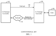
- L2 interrupt controller 102 may communicate an interrupt over bus 108 to L1 interrupt controller 104, which may be attached to core 106. As shown, core 106 is in direct communication with only L1 interrupt controller 104, and not L2 interrupt controller 102. Initially, L1 interrupt controller 104 may receive a first interrupt from L2 interrupt controller 102. Thereafter, the processing of subsequent interrupts may be handled in one of two ways, for example, based on processor resources.
- core 106 may provide an indication to L2 interrupt controller 102, through L1 interrupt controller 104, that the core 106 is ready for a new interrupt.
- L2 interrupt controller 102 may then send the processor core a second interrupt if a second interrupt is pending at L2 interrupt controller 102.
- the first interrupt may be serviced by a first thread of the multi-threaded processor, and a second thread may be in WAIT state, and available to process a second interrupt.
- the multi-threaded processor may provide an indication L2 interrupt controller 102, for example, via L1 interrupt controller 104, that L2 interrupt controller 102 may send a second interrupt, immediately after the processor core receives the first interrupt.
- core 106 may provide indication to L2 interrupt controller 102 to defer sending any new requests until a later point in time or until further notice.
- core 106 may be configured as a multi-threaded processor, all the threads may be busy, and the real-time operating system (RTOS) associated with the processor core may require a time delay in order to determine which thread to interrupt.
- the RTOS may determine which hardware thread is running a software thread with the least priority, and designate that thread as the lowest priority software thread, such that L1 interrupt controller 104 may direct a second interrupt from L2 interrupt controller 102 to the lowest priority software thread.
- the determination of the lowest priority software thread may incur significant time delay, and correspondingly, the rate at which interrupts can be processed suffers degradation.
- interrupts such as vectored addresses associated with the interrupt's ISR
- L2 interrupt controller 102 and L1 interrupt controller 104 over an Advanced Microcontroller Bus Architecture High Performance Bus (AHB).
- AHB Advanced Microcontroller Bus Architecture High Performance Bus
- WO 2006/090329 discloses a method for reducing interrupt latency time according to the preamble of claim 1.
- Exemplary embodiments of the invention are directed to systems and method for reducing interrupt latency in two level interrupt controllers configured for multi-threaded processors.
- an exemplary embodiment is directed to a method for reducing interrupt latency time, comprising: communicating a first interrupt and a first vector identifier from a second interrupt controller to a first interrupt controller; processing the first interrupt and the first vector identifier at the first interrupt controller; sending the processed interrupt from the first interrupt controller to a thread in a core; determining when the core is ready to receive a second interrupt; and sending an instruction from the core to the second interrupt controller indicating the core is ready to receive the second interrupt.
- Another exemplary embodiment is directed to a multi-threaded processor, comprising: a core, a level two interrupt controller, and a line coupling the core to the level two interrupt controller, wherein the core is configured to indicate to the level two interrupt controller, via the line, that the core is ready to receive a level two interrupt.
- Yet another exemplary embodiment is directed to a processing system configured for reduced interrupt latency, the processing system comprising: a first interrupt controller coupled to a core; means for communicating a first interrupt and a first vector identifier from a second interrupt controller to the first interrupt controller; means for processing the first interrupt and the first vector identifier at the first interrupt controller; means for sending the processed interrupt to a thread in the core; means for determining when the core is ready to receive a second interrupt; and means for sending an instruction from the core to the second interrupt controller indicating the core is ready to receive the second interrupt.
- Another exemplary embodiment is directed to a non-transitory computer-readable storage medium comprising code, which, when executed by a processor, causes the processor to perform operations for reducing interrupt latency time, the non-transitory computer-readable storage medium comprising: code for communicating a first interrupt and a first vector identifier from a second interrupt controller to a first interrupt controller; code for processing the first interrupt and the first vector identifier at the first interrupt controller; code for sending the processed interrupt from the first interrupt controller to a thread in a core; code for determining when the core is ready to receive a second interrupt; and code for sending an instruction from the core to the second interrupt controller indicating the core is ready to receive the second interrupt.
- exemplary embodiments are directed to low latency interrupt controllers configured for high rate of interrupt processing. More particularly, embodiments may include two-level low latency interrupt controllers which may be interfaced to multi-threaded processor cores.
- system 200 comprising an L1 interrupt controller 204, which may be configured for direct interfacing with multi-threaded processor 206.
- L1 interrupt controller 204 may handle interrupts directed to the multi-threaded processor from one or more devices, including L2 interrupt controller 202.
- both L1 and L2 interrupt controllers 204 and 202 may be a Vectored Interrupt Controller, such as previously described. Accordingly, the L2 interrupt controller 202 may be configured to send interrupts along with vector addresses associated with ISRs of the interrupts. According to a non-limiting illustration, the L2 interrupt controller 202 may support up to 1024 low-latency interrupts. The 1024 low latency interrupts may be prioritized by L2 interrupt controller 202.
- L1 interrupt controller 204 may be a VIC with 32 register entries [31:0], such that register entry [31] of L1 interrupt controller 204 may correspond to L2 interrupt controller 202.
- L1 interrupt controller 204 may be reserved for interrupts from other sources, including interrupts that are generated internally from the two or more threads of multi-threaded processor 206 for thread-to-thread signaling, or for legacy applications.
- all interrupts from external devices may first be received at L2 interrupt controller 202 and thereafter may be directed to L1 interrupt controller 204.
- a first interrupt may be received by L2 interrupt controller 202 from an external device (not shown).
- the first interrupt may be communicated to L1 interrupt controller 204 over bus 208, along with corresponding vector ID on bus 210.
- a global vector ID register (not shown) may also be updated with the vector ID, wherein the global vector ID register may be accessible through a control register (CR) transfer instruction.
- the global vector ID register may assist in tracking interrupts.
- the global VID register may be configured to track which specific L2 interrupt was sent to L1 interrupt controller 204.
- embodiments may deviate from conventional techniques in several ways in order to expedite the handling of subsequent requests. While conventional techniques such as illustrated in FIG. 1 , relied on hardware solutions to inform L2 interrupt controller 102 over network 110 regarding the availability of core 106 for accepting a new request, embodiments may include software routines configured for monitoring the readiness of multi-threaded processor 206. For example, a software routine may efficiently track the state of processes running on the two or more threads of multi-threaded processor 206. The software routine may determine whether one or more threads may be in a WAIT state to immediately accept a new interrupt, or if a low priority process running on a thread may be interrupted to immediately service a new interrupt.
- embodiments may include a single instruction to accomplish both: informing L1 interrupt controller 204 that the first interrupt has been accepted for processing and also informing L2 interrupt controller 202 that multi-threaded processor 206 is now ready for accepting a new interrupt. It will be recognized that these embodiments are not restrained by a conventional two-level interrupt framework, such as illustrated in FIG. 1 , wherein core 106 may communicate its readiness to L2 interrupt controller 102 for a new interrupt only through network 110. On the other hand, embodiments may communicate the readiness of multi-threaded processor 206 directly to L2 interrupt controller 202, through a dedicated hardware line, such as line 212 in FIG. 2 .
- some embodiments may also include a dedicated hardware port in multi-threaded processor 206, such that L2 interrupt controller 202 may directly communicate interrupts (e.g. "New interrupt" in FIG. 2 ) to multi-threaded processor 206 via a dedicated hardware line, such as line 214.
- interrupts e.g. "New interrupt" in FIG. 2
- line 214 a dedicated hardware line
- Exemplary embodiments may include a Clear Interrupt Auto Disable (CIAD) register.
- a CIAD instruction may be used to ensure that the same interrupt is not taken more than once. For example, multi-threaded processor 206 may automatically set the CIAD register as soon as a first interrupt is taken. Once it is determined, for example by a software routine as discussed previously, that multi-threaded processor 206 is ready for accepting a new interrupt, the software routine may trigger a CIAD instruction to be issued. The CIAD instruction may then clear the CIAD register to activate the interrupt line such that a new interrupt may be taken on the same line.
- the CIAD instruction may be issued by multi-threaded processor 206 to both clear a status indicating that the first interrupt is pending at L1 interrupt controller 204 and also inform L2 interrupt controller 202 that multi-threaded processor 206 is ready to receive another interrupt and accompanying vector ID over buses 208 and 210 respectively.
- the CIAD instruction may be associated with register entry [31] of L1 interrupt controller 204, which as previously described, may be dedicated for interrupts from L2 interrupt controller 202.
- the CIAD instruction may provide an effective handshake mechanism between L2 interrupt controller 202, L1 interrupt controller 204 and multi-threaded processor 206.
- the process such as, a software routine, may be started to generate the CIAD instruction, for expediting the handling of subsequent interrupts. It will be understood that embodiments may also implement the above processes with dedicated hardware or a combination of hardware and software, without being limited to a software routine as discussed in the aforementioned example.
- embodiments may include implementations wherein register entry [31] of L1 interrupt controller 204 may be programmed to capture information on a rising edge of a clock.
- L2 interrupt controller 202 may be either edge triggered or level sensitive, and send interrupts and corresponding vector IDs to L1 interrupt controller 204 over buses 208 and 210 asynchronously.
- the interrupts may be synchronized to a clock corresponding to multi-threaded processor 206.
- Such edge triggered configurations may enable improved communication protocols between L1 interrupt controller 204 and L2 interrupt controller 202.
- multi-threaded processor 206 may begin the transition to a state of readiness to accept a new interrupt, for example, by clearing register entry [31] of L1 interrupt controller 204.
- embodiments may significantly improve the rate of processing interrupts and also decrease the latency of interrupt processing.
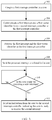
- an embodiment can include a method for reducing interrupt latency time, comprising: coupling a first interrupt controller, such as L1 interrupt controller 204, to a core, such as multi-threaded processor 206 (Block 302); communicating a first interrupt and a first vector identifier from a second interrupt controller, such as L2 interrupt controller 202 to the first interrupt controller, for example over buses 208 and 210 respectively (Block 304); processing the first interrupt and the first vector identifier at the first interrupt controller (Block 306); sending the processed interrupt to a thread in the core (Block 308); determining when the core is ready to receive a second interrupt (Block 310); and sending an instruction from the core to the second interrupt controller indicating the core is ready to receive the second interrupt (Block 312).
- a first interrupt controller such as L1 interrupt controller 204
- a core such as multi-threaded processor 206
- a software module may reside in RAM memory, flash memory, ROM memory, EPROM memory, EEPROM memory, registers, hard disk, a removable disk, a CD-ROM, or any other form of storage medium known in the art.
- An exemplary storage medium is coupled to the processor such that the processor can read information from, and write information to, the storage medium. In the alternative, the storage medium may be integral to the processor.
- an embodiment of the invention can include a computer readable media embodying a method for reducing interrupt latency in a two-level interrupt controller interface to a multi-threaded processor. Accordingly, the invention is not limited to illustrated examples and any means for performing the functionality described herein are included in embodiments of the invention.
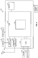
- FIG. 4 a block diagram of a particular illustrative embodiment of a wireless device that includes a multi-core processor configured according to exemplary embodiments is depicted and generally designated 400.
- the device 400 includes a digital signal processor (DSP) 464 which may include system 200 of FIG. 2 .
- DSP digital signal processor
- FIG. 4 also shows display controller 426 that is coupled to DSP 464 and to display 428.
- Coder/decoder (CODEC) 434 e.g., an audio and/or voice CODEC
- Other components, such as wireless controller 440 (which may include a modem) are also illustrated.
- Speaker 436 and microphone 438 can be coupled to CODEC 434.
- wireless controller 440 can be coupled to wireless antenna 442.
- DSP 464, display controller 426, memory 432, CODEC 434, and wireless controller 440 are included in a system-in-package or system-on-chip device 422.
- input device 430 and power supply 444 are coupled to the system-on-chip device 422.
- display 428, input device 430, speaker 436, microphone 438, wireless antenna 442, and power supply 444 are external to the system-on-chip device 422.
- each of display 428, input device 430, speaker 436, microphone 438, wireless antenna 442, and power supply 444 can be coupled to a component of the system-on-chip device 422, such as an interface or a controller.
- FIG. 4 depicts a wireless communications device
- DSP 464 and memory 432 may also be integrated into a set-top box, a music player, a video player, an entertainment unit, a navigation device, a personal digital assistant (PDA), a fixed location data unit, or a computer.
- a processor e.g., DSP 464 may also be integrated into such a device.
- the foregoing disclosed devices and methods are typically designed and are configured into GDSII and GERBER computer files, stored on a computer readable media. These files are in turn provided to fabrication handlers who fabricate devices based on these files. The resulting products are semiconductor wafers that are then cut into semiconductor die and packaged into a semiconductor chip. The chips are then employed in devices described above.
Landscapes
- Engineering & Computer Science (AREA)
- Theoretical Computer Science (AREA)
- Physics & Mathematics (AREA)
- General Engineering & Computer Science (AREA)
- General Physics & Mathematics (AREA)
- Bus Control (AREA)
- Human Computer Interaction (AREA)
Applications Claiming Priority (2)
| Application Number | Priority Date | Filing Date | Title |
|---|---|---|---|
| US13/252,670 US8972642B2 (en) | 2011-10-04 | 2011-10-04 | Low latency two-level interrupt controller interface to multi-threaded processor |
| PCT/US2012/058780 WO2013052684A2 (en) | 2011-10-04 | 2012-10-04 | Low latency two-level interrupt controller interface to multi-threaded processor |
Publications (2)
| Publication Number | Publication Date |
|---|---|
| EP2764442A2 EP2764442A2 (en) | 2014-08-13 |
| EP2764442B1 true EP2764442B1 (en) | 2016-01-20 |
Family
ID=47172881
Family Applications (1)
| Application Number | Title | Priority Date | Filing Date |
|---|---|---|---|
| EP12784381.1A Not-in-force EP2764442B1 (en) | 2011-10-04 | 2012-10-04 | Low latency two-level interrupt controller interface to multi-threaded processor |
Country Status (6)
| Country | Link |
|---|---|
| US (1) | US8972642B2 (enExample) |
| EP (1) | EP2764442B1 (enExample) |
| JP (2) | JP5847949B2 (enExample) |
| KR (1) | KR101563576B1 (enExample) |
| CN (1) | CN103874990B (enExample) |
| WO (1) | WO2013052684A2 (enExample) |
Families Citing this family (9)
| Publication number | Priority date | Publication date | Assignee | Title |
|---|---|---|---|---|
| US8972642B2 (en) * | 2011-10-04 | 2015-03-03 | Qualcomm Incorporated | Low latency two-level interrupt controller interface to multi-threaded processor |
| US9110830B2 (en) * | 2012-01-18 | 2015-08-18 | Qualcomm Incorporated | Determining cache hit/miss of aliased addresses in virtually-tagged cache(s), and related systems and methods |
| US10394730B2 (en) * | 2014-11-14 | 2019-08-27 | Cavium, Llc | Distributed interrupt scheme in a multi-processor system |
| US10067892B2 (en) * | 2015-03-06 | 2018-09-04 | Microchip Technology Incorporated | Microcontroller or microprocessor with dual mode interrupt |
| US11630789B2 (en) * | 2020-09-11 | 2023-04-18 | Apple Inc. | Scalable interrupts |
| US11507414B2 (en) | 2020-11-25 | 2022-11-22 | Cadence Design Systems, Inc. | Circuit for fast interrupt handling |
| US12020066B2 (en) | 2021-06-11 | 2024-06-25 | International Busin ess Machines Corporation | Asynchronous completion notification in a multi-core data processing system |
| US11755362B2 (en) | 2021-06-11 | 2023-09-12 | International Business Machines Corporation | Techniques for handling escalation of interrupts in a data processing system |
| US11645215B2 (en) | 2021-06-11 | 2023-05-09 | International Business Machines Corporation | Efficient selection of a particular processor thread for handling an interrupt |
Family Cites Families (41)
| Publication number | Priority date | Publication date | Assignee | Title |
|---|---|---|---|---|
| US4420806A (en) * | 1981-01-15 | 1983-12-13 | Harris Corporation | Interrupt coupling and monitoring system |
| US5555420A (en) * | 1990-12-21 | 1996-09-10 | Intel Corporation | Multiprocessor programmable interrupt controller system with separate interrupt bus and bus retry management |
| US5805841A (en) * | 1991-07-24 | 1998-09-08 | Micron Electronics, Inc. | Symmetric parallel multi-processing bus architeture |
| US5367689A (en) * | 1992-10-02 | 1994-11-22 | Compaq Computer Corporation | Apparatus for strictly ordered input/output operations for interrupt system integrity |
| US5530872A (en) * | 1992-12-23 | 1996-06-25 | International Business Machines Corporation | Method and system for directing device driver to service multiple sequential interrupt requests generated by I/O device connected thereto |
| DE19501674A1 (de) * | 1994-02-03 | 1995-08-10 | Tektronix Inc | Verwaltung der Datenübertragung zwischen Prozessoren |
| DE4406094C2 (de) | 1994-02-25 | 2000-04-13 | Lp Elektronik Gmbh | Vorrichtung zum Betrieb einer Steuerungsanwendung |
| US5745772A (en) | 1996-08-02 | 1998-04-28 | Micron Electronics, Inc. | Advanced programmable interrupt controller |
| US5944809A (en) * | 1996-08-20 | 1999-08-31 | Compaq Computer Corporation | Method and apparatus for distributing interrupts in a symmetric multiprocessor system |
| US5905897A (en) * | 1997-03-20 | 1999-05-18 | Industrial Technology Research Institute | Method and apparatus for selecting a nonblocked interrupt request |
| US6418496B2 (en) * | 1997-12-10 | 2002-07-09 | Intel Corporation | System and apparatus including lowest priority logic to select a processor to receive an interrupt message |
| US6356354B1 (en) * | 1998-09-18 | 2002-03-12 | Hewlett-Packard Co. | System having an arithmetic-logic circuit for determining the maximum or minimum of a plurality of codes |
| IT1308343B1 (it) * | 1999-02-03 | 2001-12-11 | St Microelectronics Srl | Procedimento per arbitrare priorita' di interruzione tra periferichein un sistema basato su microprocessore |
| US6477600B1 (en) * | 1999-06-08 | 2002-11-05 | Intel Corporation | Apparatus and method for processing isochronous interrupts |
| JP3769428B2 (ja) * | 1999-09-30 | 2006-04-26 | 富士通株式会社 | 浮動割込みを保留できる情報処理装置および割込み条件変更命令実行方法 |
| US6662297B1 (en) * | 1999-12-30 | 2003-12-09 | Intel Corporation | Allocation of processor bandwidth by inserting interrupt servicing instructions to intervene main program in instruction queue mechanism |
| US6772241B1 (en) * | 2000-09-29 | 2004-08-03 | Intel Corporation | Selective interrupt delivery to multiple processors having independent operating systems |
| US20040111593A1 (en) | 2002-12-05 | 2004-06-10 | International Business Machines Corporation | Interrupt handler prediction method and system |
| US20040117532A1 (en) * | 2002-12-11 | 2004-06-17 | Bennett Steven M. | Mechanism for controlling external interrupts in a virtual machine system |
| US7350005B2 (en) | 2003-05-23 | 2008-03-25 | Arm Limited | Handling interrupts in a system having multiple data processing units |
| US7051146B2 (en) * | 2003-06-25 | 2006-05-23 | Lsi Logic Corporation | Data processing systems including high performance buses and interfaces, and associated communication methods |
| GB2403822B (en) * | 2003-07-07 | 2006-05-10 | Advanced Risc Mach Ltd | Data processing apparatus and method for handling interrupts |
| US7177967B2 (en) * | 2003-09-30 | 2007-02-13 | Intel Corporation | Chipset support for managing hardware interrupts in a virtual machine system |
| US7237051B2 (en) * | 2003-09-30 | 2007-06-26 | Intel Corporation | Mechanism to control hardware interrupt acknowledgement in a virtual machine system |
| DE10361364B4 (de) * | 2003-12-29 | 2010-07-01 | Advanced Micro Devices, Inc., Sunnyvale | Vorrichtung zum Behandeln von Interruptereignissen, mit der pegel-sensitive bzw. level-sensitive Interruptanforderungen in flankengetriggerten Interruptnachrichten umgesetzt werden |
| JP4564011B2 (ja) * | 2004-08-27 | 2010-10-20 | パナソニック株式会社 | 情報処理装置、例外制御回路 |
| US7769937B2 (en) * | 2005-02-28 | 2010-08-03 | Koninklijke Philips Electronics N.V. | Data processing system with interrupt controller and interrupt controlling method |
| JP2006331156A (ja) * | 2005-05-27 | 2006-12-07 | Renesas Technology Corp | 半導体装置 |
| US7424563B2 (en) * | 2006-02-24 | 2008-09-09 | Qualcomm Incorporated | Two-level interrupt service routine |
| US7533207B2 (en) * | 2006-12-06 | 2009-05-12 | Microsoft Corporation | Optimized interrupt delivery in a virtualized environment |
| JP4249779B2 (ja) * | 2006-12-25 | 2009-04-08 | 株式会社東芝 | デバイス制御装置 |
| US7769938B2 (en) * | 2007-09-06 | 2010-08-03 | Intel Corporation | Processor selection for an interrupt identifying a processor cluster |
| US7657683B2 (en) | 2008-02-01 | 2010-02-02 | Redpine Signals, Inc. | Cross-thread interrupt controller for a multi-thread processor |
| US8291202B2 (en) * | 2008-08-08 | 2012-10-16 | Qualcomm Incorporated | Apparatus and methods for speculative interrupt vector prefetching |
| US7849247B2 (en) | 2008-10-14 | 2010-12-07 | Freescale Semiconductor, Inc. | Interrupt controller for accelerated interrupt handling in a data processing system and method thereof |
| US8302109B2 (en) * | 2009-02-24 | 2012-10-30 | International Business Machines Corporation | Synchronization optimized queuing system |
| US8234431B2 (en) * | 2009-10-13 | 2012-07-31 | Empire Technology Development Llc | Interrupt masking for multi-core processors |
| US8312195B2 (en) * | 2010-02-18 | 2012-11-13 | Red Hat, Inc. | Managing interrupts using a preferred binding between a device generating interrupts and a CPU |
| US8458386B2 (en) * | 2010-12-07 | 2013-06-04 | Apple Inc. | Atomic interrupt masking in an interrupt controller to prevent delivery of same interrupt vector for consecutive interrupt acknowledgements |
| US8688883B2 (en) * | 2011-09-08 | 2014-04-01 | Intel Corporation | Increasing turbo mode residency of a processor |
| US8972642B2 (en) * | 2011-10-04 | 2015-03-03 | Qualcomm Incorporated | Low latency two-level interrupt controller interface to multi-threaded processor |
-
2011
- 2011-10-04 US US13/252,670 patent/US8972642B2/en active Active
-
2012
- 2012-10-04 WO PCT/US2012/058780 patent/WO2013052684A2/en not_active Ceased
- 2012-10-04 KR KR1020147012326A patent/KR101563576B1/ko not_active Expired - Fee Related
- 2012-10-04 CN CN201280048379.2A patent/CN103874990B/zh active Active
- 2012-10-04 JP JP2014534728A patent/JP5847949B2/ja not_active Expired - Fee Related
- 2012-10-04 EP EP12784381.1A patent/EP2764442B1/en not_active Not-in-force
-
2015
- 2015-11-25 JP JP2015229471A patent/JP6153991B2/ja not_active Expired - Fee Related
Also Published As
| Publication number | Publication date |
|---|---|
| US8972642B2 (en) | 2015-03-03 |
| WO2013052684A3 (en) | 2013-06-20 |
| JP2014534506A (ja) | 2014-12-18 |
| JP2016095855A (ja) | 2016-05-26 |
| CN103874990B (zh) | 2016-08-17 |
| JP6153991B2 (ja) | 2017-06-28 |
| US20130086290A1 (en) | 2013-04-04 |
| KR101563576B1 (ko) | 2015-10-27 |
| EP2764442A2 (en) | 2014-08-13 |
| KR20140082787A (ko) | 2014-07-02 |
| JP5847949B2 (ja) | 2016-01-27 |
| WO2013052684A2 (en) | 2013-04-11 |
| CN103874990A (zh) | 2014-06-18 |
Similar Documents
| Publication | Publication Date | Title |
|---|---|---|
| EP2764442B1 (en) | Low latency two-level interrupt controller interface to multi-threaded processor | |
| EP2850515B1 (en) | Fusing conditional write instructions having opposite conditions in instruction processing circuits, and related processor systems, methods, and computer-readable media | |
| EP2972787B1 (en) | Eliminating redundant synchronization barriers in instruction processing circuits, and related processor systems, methods, and computer-readable media | |
| RU2651238C2 (ru) | Синхронизация обработки прерывания для уменьшения потребления энергии | |
| US20140223115A1 (en) | Managing out-of-order memory command execution from multiple queues while maintaining data coherency | |
| US11843550B2 (en) | Packet processing with reduced latency | |
| US20080034146A1 (en) | Systems and Methods for Transactions Between Processor and Memory | |
| EP3118738B1 (en) | Method and system for processing interruptible instructions in a microcontroller | |
| CN107015931A (zh) | 用于中断处理的方法和加速器单元 | |
| CN105487989A (zh) | 一种降低响应延时提高系统效率的中断控制器及控制方法 | |
| US20140089646A1 (en) | Processor with interruptable instruction execution | |
| EP2856304B1 (en) | Issuing instructions to execution pipelines based on register-associated preferences, and related instruction processing circuits, processor systems, methods, and computer-readable media | |
| US20130013840A1 (en) | Single pipe non-blocking architecture | |
| WO2013163161A1 (en) | Eliminating redundant masking operations in instruction processing circuits, and related processor systems, methods, and computer-readable media | |
| EP3335111B1 (en) | Predicting memory instruction punts in a computer processor using a punt avoidance table (pat) | |
| US20200356372A1 (en) | Early instruction execution with value prediction and local register file | |
| US9146776B1 (en) | Systems and methods for controlling flow of message signaled interrupts | |
| JP6066807B2 (ja) | 計算機システム、計算機システムの割込み処理プログラム及び計算機システムの割込み処理方法 | |
| US20160124771A1 (en) | Throttling circuitry | |
| US10216671B2 (en) | Power aware arbitration for bus access | |
| US9665508B2 (en) | Method and an apparatus for converting interrupts into scheduled events | |
| US9612834B2 (en) | Processor with variable instruction atomicity | |
| WO2013090605A2 (en) | Saving and restoring shader context state and resuming a faulted apd wavefront |
Legal Events
| Date | Code | Title | Description |
|---|---|---|---|
| PUAI | Public reference made under article 153(3) epc to a published international application that has entered the european phase |
Free format text: ORIGINAL CODE: 0009012 |
|
| 17P | Request for examination filed |
Effective date: 20140310 |
|
| AK | Designated contracting states |
Kind code of ref document: A2 Designated state(s): AL AT BE BG CH CY CZ DE DK EE ES FI FR GB GR HR HU IE IS IT LI LT LU LV MC MK MT NL NO PL PT RO RS SE SI SK SM TR |
|
| DAX | Request for extension of the european patent (deleted) | ||
| GRAP | Despatch of communication of intention to grant a patent |
Free format text: ORIGINAL CODE: EPIDOSNIGR1 |
|
| INTG | Intention to grant announced |
Effective date: 20150804 |
|
| GRAS | Grant fee paid |
Free format text: ORIGINAL CODE: EPIDOSNIGR3 |
|
| GRAA | (expected) grant |
Free format text: ORIGINAL CODE: 0009210 |
|
| AK | Designated contracting states |
Kind code of ref document: B1 Designated state(s): AL AT BE BG CH CY CZ DE DK EE ES FI FR GB GR HR HU IE IS IT LI LT LU LV MC MK MT NL NO PL PT RO RS SE SI SK SM TR |
|
| REG | Reference to a national code |
Ref country code: GB Ref legal event code: FG4D |
|
| REG | Reference to a national code |
Ref country code: CH Ref legal event code: EP |
|
| REG | Reference to a national code |
Ref country code: IE Ref legal event code: FG4D |
|
| REG | Reference to a national code |
Ref country code: AT Ref legal event code: REF Ref document number: 772027 Country of ref document: AT Kind code of ref document: T Effective date: 20160215 |
|
| REG | Reference to a national code |
Ref country code: DE Ref legal event code: R096 Ref document number: 602012014201 Country of ref document: DE |
|
| REG | Reference to a national code |
Ref country code: LT Ref legal event code: MG4D Ref country code: NL Ref legal event code: MP Effective date: 20160120 |
|
| REG | Reference to a national code |
Ref country code: AT Ref legal event code: MK05 Ref document number: 772027 Country of ref document: AT Kind code of ref document: T Effective date: 20160120 |
|
| PG25 | Lapsed in a contracting state [announced via postgrant information from national office to epo] |
Ref country code: NL Free format text: LAPSE BECAUSE OF FAILURE TO SUBMIT A TRANSLATION OF THE DESCRIPTION OR TO PAY THE FEE WITHIN THE PRESCRIBED TIME-LIMIT Effective date: 20160120 |
|
| PG25 | Lapsed in a contracting state [announced via postgrant information from national office to epo] |
Ref country code: NO Free format text: LAPSE BECAUSE OF FAILURE TO SUBMIT A TRANSLATION OF THE DESCRIPTION OR TO PAY THE FEE WITHIN THE PRESCRIBED TIME-LIMIT Effective date: 20160420 Ref country code: IT Free format text: LAPSE BECAUSE OF FAILURE TO SUBMIT A TRANSLATION OF THE DESCRIPTION OR TO PAY THE FEE WITHIN THE PRESCRIBED TIME-LIMIT Effective date: 20160120 Ref country code: ES Free format text: LAPSE BECAUSE OF FAILURE TO SUBMIT A TRANSLATION OF THE DESCRIPTION OR TO PAY THE FEE WITHIN THE PRESCRIBED TIME-LIMIT Effective date: 20160120 Ref country code: GR Free format text: LAPSE BECAUSE OF FAILURE TO SUBMIT A TRANSLATION OF THE DESCRIPTION OR TO PAY THE FEE WITHIN THE PRESCRIBED TIME-LIMIT Effective date: 20160421 Ref country code: HR Free format text: LAPSE BECAUSE OF FAILURE TO SUBMIT A TRANSLATION OF THE DESCRIPTION OR TO PAY THE FEE WITHIN THE PRESCRIBED TIME-LIMIT Effective date: 20160120 Ref country code: FI Free format text: LAPSE BECAUSE OF FAILURE TO SUBMIT A TRANSLATION OF THE DESCRIPTION OR TO PAY THE FEE WITHIN THE PRESCRIBED TIME-LIMIT Effective date: 20160120 |
|
| PG25 | Lapsed in a contracting state [announced via postgrant information from national office to epo] |
Ref country code: PT Free format text: LAPSE BECAUSE OF FAILURE TO SUBMIT A TRANSLATION OF THE DESCRIPTION OR TO PAY THE FEE WITHIN THE PRESCRIBED TIME-LIMIT Effective date: 20160520 Ref country code: PL Free format text: LAPSE BECAUSE OF FAILURE TO SUBMIT A TRANSLATION OF THE DESCRIPTION OR TO PAY THE FEE WITHIN THE PRESCRIBED TIME-LIMIT Effective date: 20160120 Ref country code: IS Free format text: LAPSE BECAUSE OF FAILURE TO SUBMIT A TRANSLATION OF THE DESCRIPTION OR TO PAY THE FEE WITHIN THE PRESCRIBED TIME-LIMIT Effective date: 20160520 Ref country code: LV Free format text: LAPSE BECAUSE OF FAILURE TO SUBMIT A TRANSLATION OF THE DESCRIPTION OR TO PAY THE FEE WITHIN THE PRESCRIBED TIME-LIMIT Effective date: 20160120 Ref country code: SE Free format text: LAPSE BECAUSE OF FAILURE TO SUBMIT A TRANSLATION OF THE DESCRIPTION OR TO PAY THE FEE WITHIN THE PRESCRIBED TIME-LIMIT Effective date: 20160120 Ref country code: RS Free format text: LAPSE BECAUSE OF FAILURE TO SUBMIT A TRANSLATION OF THE DESCRIPTION OR TO PAY THE FEE WITHIN THE PRESCRIBED TIME-LIMIT Effective date: 20160120 Ref country code: AT Free format text: LAPSE BECAUSE OF FAILURE TO SUBMIT A TRANSLATION OF THE DESCRIPTION OR TO PAY THE FEE WITHIN THE PRESCRIBED TIME-LIMIT Effective date: 20160120 Ref country code: LT Free format text: LAPSE BECAUSE OF FAILURE TO SUBMIT A TRANSLATION OF THE DESCRIPTION OR TO PAY THE FEE WITHIN THE PRESCRIBED TIME-LIMIT Effective date: 20160120 |
|
| REG | Reference to a national code |
Ref country code: FR Ref legal event code: PLFP Year of fee payment: 5 |
|
| REG | Reference to a national code |
Ref country code: DE Ref legal event code: R097 Ref document number: 602012014201 Country of ref document: DE |
|
| PG25 | Lapsed in a contracting state [announced via postgrant information from national office to epo] |
Ref country code: EE Free format text: LAPSE BECAUSE OF FAILURE TO SUBMIT A TRANSLATION OF THE DESCRIPTION OR TO PAY THE FEE WITHIN THE PRESCRIBED TIME-LIMIT Effective date: 20160120 Ref country code: DK Free format text: LAPSE BECAUSE OF FAILURE TO SUBMIT A TRANSLATION OF THE DESCRIPTION OR TO PAY THE FEE WITHIN THE PRESCRIBED TIME-LIMIT Effective date: 20160120 |
|
| PLBE | No opposition filed within time limit |
Free format text: ORIGINAL CODE: 0009261 |
|
| STAA | Information on the status of an ep patent application or granted ep patent |
Free format text: STATUS: NO OPPOSITION FILED WITHIN TIME LIMIT |
|
| PG25 | Lapsed in a contracting state [announced via postgrant information from national office to epo] |
Ref country code: SK Free format text: LAPSE BECAUSE OF FAILURE TO SUBMIT A TRANSLATION OF THE DESCRIPTION OR TO PAY THE FEE WITHIN THE PRESCRIBED TIME-LIMIT Effective date: 20160120 Ref country code: CZ Free format text: LAPSE BECAUSE OF FAILURE TO SUBMIT A TRANSLATION OF THE DESCRIPTION OR TO PAY THE FEE WITHIN THE PRESCRIBED TIME-LIMIT Effective date: 20160120 Ref country code: SM Free format text: LAPSE BECAUSE OF FAILURE TO SUBMIT A TRANSLATION OF THE DESCRIPTION OR TO PAY THE FEE WITHIN THE PRESCRIBED TIME-LIMIT Effective date: 20160120 Ref country code: RO Free format text: LAPSE BECAUSE OF FAILURE TO SUBMIT A TRANSLATION OF THE DESCRIPTION OR TO PAY THE FEE WITHIN THE PRESCRIBED TIME-LIMIT Effective date: 20160120 |
|
| 26N | No opposition filed |
Effective date: 20161021 |
|
| PG25 | Lapsed in a contracting state [announced via postgrant information from national office to epo] |
Ref country code: BE Free format text: LAPSE BECAUSE OF FAILURE TO SUBMIT A TRANSLATION OF THE DESCRIPTION OR TO PAY THE FEE WITHIN THE PRESCRIBED TIME-LIMIT Effective date: 20160120 |
|
| PG25 | Lapsed in a contracting state [announced via postgrant information from national office to epo] |
Ref country code: BG Free format text: LAPSE BECAUSE OF FAILURE TO SUBMIT A TRANSLATION OF THE DESCRIPTION OR TO PAY THE FEE WITHIN THE PRESCRIBED TIME-LIMIT Effective date: 20160420 Ref country code: SI Free format text: LAPSE BECAUSE OF FAILURE TO SUBMIT A TRANSLATION OF THE DESCRIPTION OR TO PAY THE FEE WITHIN THE PRESCRIBED TIME-LIMIT Effective date: 20160120 |
|
| REG | Reference to a national code |
Ref country code: CH Ref legal event code: PL |
|
| REG | Reference to a national code |
Ref country code: IE Ref legal event code: MM4A |
|
| PG25 | Lapsed in a contracting state [announced via postgrant information from national office to epo] |
Ref country code: LI Free format text: LAPSE BECAUSE OF NON-PAYMENT OF DUE FEES Effective date: 20161031 Ref country code: CH Free format text: LAPSE BECAUSE OF NON-PAYMENT OF DUE FEES Effective date: 20161031 |
|
| PG25 | Lapsed in a contracting state [announced via postgrant information from national office to epo] |
Ref country code: LU Free format text: LAPSE BECAUSE OF NON-PAYMENT OF DUE FEES Effective date: 20161004 |
|
| REG | Reference to a national code |
Ref country code: FR Ref legal event code: PLFP Year of fee payment: 6 |
|
| PG25 | Lapsed in a contracting state [announced via postgrant information from national office to epo] |
Ref country code: IE Free format text: LAPSE BECAUSE OF NON-PAYMENT OF DUE FEES Effective date: 20161004 |
|
| PG25 | Lapsed in a contracting state [announced via postgrant information from national office to epo] |
Ref country code: HU Free format text: LAPSE BECAUSE OF FAILURE TO SUBMIT A TRANSLATION OF THE DESCRIPTION OR TO PAY THE FEE WITHIN THE PRESCRIBED TIME-LIMIT; INVALID AB INITIO Effective date: 20121004 |
|
| PG25 | Lapsed in a contracting state [announced via postgrant information from national office to epo] |
Ref country code: MK Free format text: LAPSE BECAUSE OF FAILURE TO SUBMIT A TRANSLATION OF THE DESCRIPTION OR TO PAY THE FEE WITHIN THE PRESCRIBED TIME-LIMIT Effective date: 20160120 Ref country code: MT Free format text: LAPSE BECAUSE OF NON-PAYMENT OF DUE FEES Effective date: 20161031 Ref country code: MC Free format text: LAPSE BECAUSE OF FAILURE TO SUBMIT A TRANSLATION OF THE DESCRIPTION OR TO PAY THE FEE WITHIN THE PRESCRIBED TIME-LIMIT Effective date: 20160120 Ref country code: CY Free format text: LAPSE BECAUSE OF FAILURE TO SUBMIT A TRANSLATION OF THE DESCRIPTION OR TO PAY THE FEE WITHIN THE PRESCRIBED TIME-LIMIT Effective date: 20160120 |
|
| REG | Reference to a national code |
Ref country code: FR Ref legal event code: PLFP Year of fee payment: 7 |
|
| PG25 | Lapsed in a contracting state [announced via postgrant information from national office to epo] |
Ref country code: TR Free format text: LAPSE BECAUSE OF FAILURE TO SUBMIT A TRANSLATION OF THE DESCRIPTION OR TO PAY THE FEE WITHIN THE PRESCRIBED TIME-LIMIT Effective date: 20160120 Ref country code: AL Free format text: LAPSE BECAUSE OF FAILURE TO SUBMIT A TRANSLATION OF THE DESCRIPTION OR TO PAY THE FEE WITHIN THE PRESCRIBED TIME-LIMIT Effective date: 20160120 |
|
| PGFP | Annual fee paid to national office [announced via postgrant information from national office to epo] |
Ref country code: FR Payment date: 20190924 Year of fee payment: 8 |
|
| PGFP | Annual fee paid to national office [announced via postgrant information from national office to epo] |
Ref country code: GB Payment date: 20190925 Year of fee payment: 8 |
|
| GBPC | Gb: european patent ceased through non-payment of renewal fee |
Effective date: 20201004 |
|
| PG25 | Lapsed in a contracting state [announced via postgrant information from national office to epo] |
Ref country code: FR Free format text: LAPSE BECAUSE OF NON-PAYMENT OF DUE FEES Effective date: 20201031 |
|
| PG25 | Lapsed in a contracting state [announced via postgrant information from national office to epo] |
Ref country code: GB Free format text: LAPSE BECAUSE OF NON-PAYMENT OF DUE FEES Effective date: 20201004 |
|
| PGFP | Annual fee paid to national office [announced via postgrant information from national office to epo] |
Ref country code: DE Payment date: 20220914 Year of fee payment: 11 |
|
| REG | Reference to a national code |
Ref country code: DE Ref legal event code: R119 Ref document number: 602012014201 Country of ref document: DE |
|
| PG25 | Lapsed in a contracting state [announced via postgrant information from national office to epo] |
Ref country code: DE Free format text: LAPSE BECAUSE OF NON-PAYMENT OF DUE FEES Effective date: 20240501 |