EP2762384A1 - Hilfsvorrichtung für den entwurf einer lenkvorrichtung und hilfsverfahren für den entwurf einer lenkvorrichtung - Google Patents
Hilfsvorrichtung für den entwurf einer lenkvorrichtung und hilfsverfahren für den entwurf einer lenkvorrichtung Download PDFInfo
- Publication number
- EP2762384A1 EP2762384A1 EP12813248.7A EP12813248A EP2762384A1 EP 2762384 A1 EP2762384 A1 EP 2762384A1 EP 12813248 A EP12813248 A EP 12813248A EP 2762384 A1 EP2762384 A1 EP 2762384A1
- Authority
- EP
- European Patent Office
- Prior art keywords
- yoke
- shaft
- candidate component
- candidate
- tube
- Prior art date
- Legal status (The legal status is an assumption and is not a legal conclusion. Google has not performed a legal analysis and makes no representation as to the accuracy of the status listed.)
- Granted
Links
Images












Classifications
-
- B—PERFORMING OPERATIONS; TRANSPORTING
- B62—LAND VEHICLES FOR TRAVELLING OTHERWISE THAN ON RAILS
- B62D—MOTOR VEHICLES; TRAILERS
- B62D1/00—Steering controls, i.e. means for initiating a change of direction of the vehicle
- B62D1/02—Steering controls, i.e. means for initiating a change of direction of the vehicle vehicle-mounted
- B62D1/16—Steering columns
-
- B—PERFORMING OPERATIONS; TRANSPORTING
- B62—LAND VEHICLES FOR TRAVELLING OTHERWISE THAN ON RAILS
- B62D—MOTOR VEHICLES; TRAILERS
- B62D1/00—Steering controls, i.e. means for initiating a change of direction of the vehicle
- B62D1/02—Steering controls, i.e. means for initiating a change of direction of the vehicle vehicle-mounted
- B62D1/16—Steering columns
- B62D1/20—Connecting steering column to steering gear
-
- G—PHYSICS
- G06—COMPUTING OR CALCULATING; COUNTING
- G06F—ELECTRIC DIGITAL DATA PROCESSING
- G06F30/00—Computer-aided design [CAD]
- G06F30/10—Geometric CAD
- G06F30/15—Vehicle, aircraft or watercraft design
-
- G—PHYSICS
- G06—COMPUTING OR CALCULATING; COUNTING
- G06F—ELECTRIC DIGITAL DATA PROCESSING
- G06F30/00—Computer-aided design [CAD]
- G06F30/10—Geometric CAD
- G06F30/17—Mechanical parametric or variational design
-
- B—PERFORMING OPERATIONS; TRANSPORTING
- B62—LAND VEHICLES FOR TRAVELLING OTHERWISE THAN ON RAILS
- B62D—MOTOR VEHICLES; TRAILERS
- B62D1/00—Steering controls, i.e. means for initiating a change of direction of the vehicle
- B62D1/02—Steering controls, i.e. means for initiating a change of direction of the vehicle vehicle-mounted
- B62D1/16—Steering columns
- B62D1/18—Steering columns yieldable or adjustable, e.g. tiltable
- B62D1/19—Steering columns yieldable or adjustable, e.g. tiltable incorporating energy-absorbing arrangements, e.g. by being yieldable or collapsible
- B62D1/192—Yieldable or collapsible columns
-
- G—PHYSICS
- G06—COMPUTING OR CALCULATING; COUNTING
- G06F—ELECTRIC DIGITAL DATA PROCESSING
- G06F2111/00—Details relating to CAD techniques
- G06F2111/20—Configuration CAD, e.g. designing by assembling or positioning modules selected from libraries of predesigned modules
Definitions
- the present invention relates to a design assistance device for a steering device which assists a design of a steering device of a vehicle and a method of assisting a steering device design.
- a steering device transmits a motion of a steering shaft, rotating by the operation of a handle, to a pinion shaft as an input shaft of a steering gear.
- the direction of a vehicle wheel is changed by the transmitted motion of the steering gear.
- the rotation axis of the steering shaft and the axis of the pinion shaft are not provided on the same straight line. Therefore, an intermediate shaft is provided between the steering shaft and the steering gear with a universal joint therebetween, and the end of the intermediate shaft is coupled to the steering shaft. Further, the end of the intermediate shaft is coupled to the end of the pinion shaft through the universal joint. Due to the presence of two components, the universal joint and the intermediate shaft, power is transmitted between the steering shaft and the input shaft of the steering gear which are not present on the same straight line.
- the intermediate shaft is disposed in a three-dimensional space between the steering shaft and the pinion shaft.
- the intermediate shaft module needs to be disposed so that the angle formed between the rotation axis of the steering shaft and the rotation axis of the intermediate shaft is equal to the angle formed between the axis of the steering gear and the rotation axis of the intermediate shaft.
- the steering device which operates the vehicle wheel of the vehicle is designed by a simulation technique. For example, there are techniques disclosed in Patent Literature 1 to Patent Literature 3.
- the intermediate shaft needs to be made in consideration of the conditions of the joint length between the steering shaft and the pinion shaft and the fitting length of the connection of the tube yoke and the shaft yoke constituting the intermediate shaft, and hence it takes effort in design for each of different conditions.
- the invention is made in view of the above-described circumstances, and it is an object of the invention to provide a design assistance device for a steering device and a method of assisting a steering device design which assists a design of a steering device including an intermediate shaft by using existing components of a tube yoke and a shaft yoke.
- a design assistance device for a steering device the design assistance device assisting a design of an intermediate shaft module including a tube yoke and a shaft yoke connected to the tube yoke
- the design assistance device for the steering device includes: a storage unit which stores at least information having a joint length as a distance between a first connection reference point where the intermediate shaft module is connected to a column yoke and a second connection reference point where the intermediate shaft module is connected to a pinion side yoke and a fitting length specification as a condition of a fitting length where the tube yoke and the shaft yoke are connected to each other, information of an existing component of an already designed tube yoke, and information of an existing component of an already designed shaft yoke; a candidate component extraction unit which extracts a candidate component of the tube yoke included in the joint length from the information of the existing component of the tube yoke and extracts a candidate component
- the display unit does not display the index when the fitting length where the candidate component of the tube yoke and the candidate component of the shaft yoke are combined with each other does not satisfy the fitting length specification.
- the storage unit stores a collision-contraction length specification as a condition of a collision-contraction length that is a distance in which the fitting between the tube yoke and the shaft yoke is released and the shaft yoke is movable inside the tube yoke, and the display unit does not display the index when the collision-contraction length where the candidate component of the tube yoke and the candidate component of the shaft yoke are combined with each other does not satisfy the collision-contraction length specification.
- the display unit displays a drawing of the candidate component of the tube yoke or the candidate component of the shaft yoke between the first connection reference point and the second connection reference point in synchronization with selection information of the input unit that selects the candidate component of the tube yoke or the candidate component of the shaft yoke extracted by the candidate component extraction unit.
- the display unit receives the index and displays information of a combination of the candidate component of the tube yoke and the candidate component of the shaft yoke stored in the storage unit in a three-dimensional space in which the longitudinal direction, the vertical direction, and the transverse direction of a vehicle equipped with the steering device are defined.
- the calculation unit gives a rank of selecting a combination of candidate components in accordance with priority rank information stored in the storage unit to a combination of plural candidate components of the tube yoke and the shaft yoke stored based on the instruction.
- a method of assisting a steering device design which causes a computer to assist a design of an intermediate shaft module including a tube yoke and a shaft yoke connected to the tube yoke
- the method of assisting the steering device design includes: a joint length information acquiring of acquiring information of a joint length as a distance between a first connection reference point where the intermediate shaft module is connected to a column yoke and a second connection reference point where the intermediate shaft module is connected to a pinion side yoke; a fitting length information acquiring of acquiring information of a fitting length specification as a condition of a fitting length where the tube yoke and the shaft yoke are connected to each other; a candidate component extracting of acquiring information of an existing component of an already designed tube yoke and information of an existing component of an already designed shaft yoke, extracting a candidate component of the tube yoke included in the joint length acquired in the
- the instruction for storing the combination of the candidate component of the tube yoke and the candidate component of the shaft yoke is not calculated.
- the method of assisting the steering device design further includes: a priority candidate component determining of determining a combination of prioritized candidate components with respect to the combinations of plural candidate components of the tube yoke and the shaft yoke stored based on the instruction.
- the method of assisting the steering device design further includes: displaying information of the combination of the candidate component of the tube yoke and the candidate component of the shaft yoke stored based on the instruction in a three-dimensional space in which the longitudinal direction, the vertical direction, and the transverse direction of a vehicle equipped with the steering device are defined.
- a design assistance device for a steering device that assists a design of a steering device having an intermediate shaft by using existing components of a tube yoke and a shaft yoke and to provide a method of assisting a steering device design.
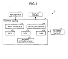
- FIG. 1 is a diagram illustrating a configuration of a design assistance device for a steering device of an embodiment.
- a design assistance device 1 for a steering device includes an input device 2, a display device 3, a control device 4, and an external storage device 5.
- the input device 2 is a mouse, a keyboard, or the like, and receives an input operation and a selection operation of a designer as a user and outputs an input signal to the control device 4.
- the display device 3 is a device such as a cathode ray tube (CRT) and a liquid crystal display on which an image is displayed.
- CTR cathode ray tube
- the control device 4 is a computer such as a personal computer (PC), and includes an input interface 4a, an output interface 4b, a central processing unit (CPU) 4c, a read only memory (ROM) 4d, a random access memory (RAM) 4e, and an internal storage device 4f.
- the input interface 4a, the output interface 4b, the CPU 4c, the ROM 4d, the RAM 4e, and the internal storage device 4f are connected to each other via an internal bus.
- the input interface 4a receives an input signal from the input device 2 and outputs the signal to the CPU 4c.
- the output interface 4b receives an image signal from the CPU 4c and outputs the signal to the display device 3.
- the ROM 4d stores a program such as a basic input output system (BIOS).
- the internal storage device 4f is, for example, a hard disk drive (HDD) or flash memory, and stores an operating system program or an application program.
- the CPU 4c is a calculation unit, and realizes various functions by executing a program stored in the ROM 4d or the internal storage device 4f while using the RAM 4e as a work area.
- the external storage device 5 is a HDD or a server.
- the external storage device 5 is connected to the control device 4 via a network such as a LAN. Further, the external storage device 5 may be disposed at a position away from the control device 4.
- the internal storage device 4f or the external storage device 5 stores an existing component database storing information of a component which constitutes a steering and has a production record. In this way, the internal storage device 4f or the external storage device 5 becomes a storage unit.
- FIG. 2 is a schematic diagram illustrating a schematic configuration of a steering device which is mounted on a vehicle.
- a vehicle 100 includes a steering device 102, a steering mechanism 103 of the steering device 102, a control unit 104, an ignition switch 105, a battery 106, and a vehicle speed sensor 107. Further, the vehicle 100 includes various general constituents of a vehicle, such as an engine and a vehicle wheel other than the constituents illustrated in FIG. 2 .
- the steering device 102 illustrated in FIG. 2 is an electric power steering device.
- the steering device 102 includes a handle (a steering wheel) 110 which is operated by a driver, a steering shaft 120 which transmits a rotation input from the handle 110, a torque sensor 130 which detects a torque input to the steering shaft 120 and a rotation angle of the steering shaft 120, and an assist steering mechanism 140 which assists the rotation of the steering shaft 120 based on the torque detected by the torque sensor 130.
- a handle a steering wheel
- the steering device 102 includes a handle (a steering wheel) 110 which is operated by a driver, a steering shaft 120 which transmits a rotation input from the handle 110, a torque sensor 130 which detects a torque input to the steering shaft 120 and a rotation angle of the steering shaft 120, and an assist steering mechanism 140 which assists the rotation of the steering shaft 120 based on the torque detected by the torque sensor 130.
- the steering device 102 detects a steering torque, which is generated in the steering shaft 120 with the operation of the handle 110, by the torque sensor 130. Further, the steering device 102 controls the driving of an electric motor 160 using the control unit 104 based on the detected signal and generates an assist steering torque so as to assist the steering force of the handle 110.
- the steering shaft 120 which is connected to the handle 110 includes an input shaft 120a to which the driver ⁇ s steering force is applied and a column output shaft 120b, and the torque sensor 130 and a speed reducing gear box 150 are interposed between the input shaft 120a and the column output shaft 120b.
- the steering force which is transmitted to the column output shaft 120b of the steering shaft 120 is transmitted to the steering mechanism 103.
- the torque sensor 130 detects the steering force which is transmitted to the input shaft 120a through the handle 110 as a steering torque.
- the assist steering mechanism 140 is connected to the column output shaft 120b of the steering shaft 120, and transmits the assist steering torque to the column output shaft 120b.
- the assist steering mechanism 140 includes the speed reducing gear box 150 which is connected to the column output shaft 120b and the electric motor 160 which is connected to the speed reducing gear box 150 and generates the assist steering torque.
- the column is constituted by the steering shaft 120, the torque sensor 130, and the speed reducing gear box 150, and the electric motor 160 gives the assist steering torque to the column output shaft 120b of the column. That is, the electric power steering device of the embodiment is of a column assisting type.
- the steering mechanism 103 of the steering device 102 includes a universal joint 20, an intermediate shaft module 10, a universal joint 30, a pinion shaft 60, a steering gear 61, and a tie-rod 70.
- the steering force which is transmitted from the steering device 102 to the steering mechanism 103 is transmitted to the pinion shaft 60 through the universal joint 20, the intermediate shaft module 10, and the universal joint 30.
- the steering force which is transmitted to the pinion shaft 60 is transmitted to the tie-rod 70 through the steering gear 61, and turns a turning wheel (not illustrated).
- the steering gear 61 is configured as a rack-and-pinion type having a pinion 61a connected to the pinion shaft 60 and a rack 61b meshing with the pinion 61a, and converts a rotation motion transmitted to the pinion 61a into a linear motion by the rack 61b.
- the control unit (ECU, Electronic Control Unit) 104 controls the driving of the vehicle 100, such as the electric motor 160, the engine, and the like. Electric power is supplied from the battery 106 to the control unit 104 when the ignition switch 105 is turned on.
- the control unit 104 calculates an assist steering instruction value of an assist instruction based on a steering torque Q detected by the torque sensor 130 and a running speed V detected by the vehicle speed sensor 107, and controls a supply current value to the electric motor 160 based on the calculated assist steering instruction value.
- the steering device 102 of the embodiment is provided with a tilt mechanism and a telescopic mechanism.
- the position of tilting the handle 110 and the position of the handle 110 in the longitudinal direction of the vehicle are adjustable.
- a handle position reference point H moves.
- the handle position reference point H is positioned on the axis T of the rotation center of the steering shaft 120.
- a connection reference point HJ of the universal joint 20 where the column output shaft 120b of the steering shaft 120 is connected to the intermediate shaft module 10 is positioned on the axis T of the rotation center of the steering shaft 120.
- the connection reference point HJ of the universal joint 20 is connected to the intermediate shaft module 10 and the universal joint 20.
- the connection reference point HJ of the universal joint 20 is positioned on the reference axis S of the rotation center of the intermediate shaft module 10.
- a connection reference point GJ of the universal joint 30 where the intermediate shaft module 10 is connected to the pinion shaft 60 is positioned on the reference axis S of the rotation center of the intermediate shaft module 10.
- the connection reference point GJ of the universal joint 30 is positioned on the axis R of the rotation center of the pinion shaft 60.
- a steering gear reference point GC which is the intersection point between the pinion shaft 60 and the steering gear 61 is also positioned on the axis R of the rotation center of the pinion shaft 60.
- FIG. 3 is a diagram illustrating an example of the intermediate shaft module.
- FIG. 4 is a diagram illustrating an example of the tube yoke and an example of the shaft yoke.
- the intermediate shaft module 10 is disposed between a column yoke 21 connected to the column output shaft 120b of the steering shaft 120 and a pinion side yoke 31 connected to the pinion shaft 60.
- the intermediate shaft module 10 includes a tube yoke 11 and a shaft yoke 14.
- One end of the tube yoke 11 is formed in a U-shape, and is provided with a pair of arm portions 12 and 12 facing each other.
- the arm portions 12 and 12 are provided with a pair of bearing holes 13 and 13 each of which faces each of the arm portions 12 and 12.
- the pivot axis which connects the hole centers of the bearing holes 13 and 13 is perpendicular to the axis as the rotation axis of the tube yoke 11.
- the intersection point between the pivot axis and the axis is the connection reference point HJ.
- a cross joint 41 is interposed between the pair of arm portions 12 and 12. Therefore, one end of the tube yoke 11 is connected to the column yoke 21 through the cross joint 41. Further, the other end of the tube yoke 11 is connectable to the shaft yoke 14.
- one end of the shaft yoke 14 is formed in a U-shape, and is provided with a pair of arm portions 15 and 15 facing each other.
- the arm portions 15 and 15 are provided with a pair of bearing holes 16 and 16 each of which faces each of the arm portions 15 and 15.
- the pivot axis which connects the hole centers of the bearing holes 16 and 16 is perpendicular to the axis as the rotation center of the tube yoke 11.
- the intersection point between the pivot axis and the axis is the connection reference point GJ.
- a cross joint 51 is interposed between the pair of arm portions 12 and 12. Therefore, one end of the shaft yoke 14 is connected to the pinion side yoke 31 through the cross joint 51. Further, the other end of the shaft yoke 14 is connectable to the tube yoke 11.
- the ends of the tube yoke 11 and the shaft yoke 14 are fitted to each other.
- the tube yoke 11 and the shaft yoke 14 are fitted to each other so that the axis as the rotation center of the tube yoke 11 and the axis as the rotation center of the shaft yoke 14 are aligned to the axis S. That is, the axis S illustrated in FIGS. 3 and 4 is a rotation axis as the rotation center of the intermediate shaft module 10.
- the tube yoke 11 includes a tube yoke fitting portion 11j which is fittable to the shaft yoke 14 at the inner peripheral side of the cylinder of the tube yoke 11, a tube yoke fitting leading end portion 11a which is a leading point of the tube yoke fitting portion 11j, and a tube yoke fitting tail end portion 11b which is a tail point of the tube yoke fitting portion 11j at the inner peripheral side of the cylinder of the tube yoke 11.
- a tube yoke length Tw is a length of the tube yoke 11 based on the connection reference point HJ.
- the shaft yoke 14 includes a shaft yoke fitting portion 14j which is fittable to the tube yoke 11 at the outer peripheral side of the cylinder of the shaft yoke 14, a shaft yoke fitting leading end portion 14a which is a leading point of the shaft yoke fitting portion 14j, and a shaft yoke fitting tail end portion 14b which is a tail point of the shaft yoke fitting portion 14j.
- a shaft yoke length Sw is a length of the shaft yoke 14 based on the connection reference point GJ.
- the tube yoke fitting portion length Lw is a length of the tube yoke fitting portion 11j
- the shaft yoke fitting portion length Swj is a length of the shaft yoke fitting portion 14j.
- a distance between the connection reference point HJ and the connection reference point GJ is referred to as a joint length W.
- the tube yoke 11 and the shaft yoke 14 are disposed so as to be fitted between the connection reference point HJ and the connection reference point GJ. For this reason, the tube yoke length Tw and the shaft yoke length Sw are smaller than the joint length W.
- a fitting length JW in which the tube yoke fitting portion 11j and the shaft yoke fitting portion 14j are fitted to each other is equal to the shaft yoke fitting portion length Swj by matching the positions of the tube yoke fitting leading end portion 11a and the shaft yoke fitting leading end portion 14a.
- the fitting length JW may be easily managed.
- the intermediate shaft module 10 of which the fitting length JW is different there is a need to design a new combination of the tube yoke 11 and the shaft yoke 14. Accordingly, there is a concern that cost increases due to an increase in the number of production components to be managed.
- the intermediate shaft module 10 transmits a steering force between the steering shaft 120 and the steering gear 61. For this reason, there is a concern that a load may be applied to the intermediate shaft module 10 from a plurality of directions. Accordingly, there is a need to design the intermediate shaft module so as to satisfy the fitting length specification which is a condition of the fitting length in response to the joint length W that prevents a backlash by a predetermined bending strength or more.
- the intermediate shaft module 10 may protect the driver in the event of a collision by being contracted in the entire length with the impact generated by the collision of the vehicle.
- the contracted distance is a collision contraction length Rw, and is a distance in which the shaft yoke 14 is movable inside the tube yoke 11 by releasing the fitting between the tube yoke 11 and the shaft yoke 14 when the impact is applied to the S axis.
- the collision contraction length Rw is a distance from the shaft yoke fitting tail end portion 14b to the cross joint 41. Further, when the fitting length JW increases, the collision contraction length Rw decreases.
- the design assistance device 1 for the steering device may provide an option of a combination of the tube yoke 11 and the shaft yoke 14 which satisfies both conditions, the fitting length specification which prevents a backlash by a predetermined bending strength or more and the collision contraction length specification which is a condition of the collision contraction length according to the specification (restriction) of the vehicle.
- the procedure of the process of the design assistance device 1 for the steering device will be described.
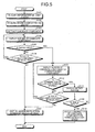
- FIG. 5 is a flowchart illustrating a procedure of a process of the design assistance device for the steering device according to First Embodiment.
- the control device 4 of the design assistance device 1 for the steering device acquires information of the joint length of the steering device 102 (step S101).
- the CPU 4c of the control device 4 reads out information of the joint length W stored in the external storage device 5 or the internal storage device 4f as design information of the vehicle input from the input device 2, and then stores the information in the RAM 4e.
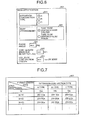
- FIG. 6 is a diagram illustrating an example of a design information input screen. Further, the design information is called, for example, the specification as the restriction condition of the vehicle 100.
- a design information input screen 601 which is disposed on the above-described display device 3 includes, for example, an input section 611, an input section 621, an input section 631, an input section 641, and an input section 651.
- the input section 611 may receive the input of the extension-contraction type of the control device 4.
- the fitting type between the tube yoke fitting portion 11j and the shaft yoke fitting portion 14j is classified into, for example, the type using a resin, the type of caulk-fitting, the type of state of serration, and the like.
- control device 4 may receive the input of the option of the case where the tube yoke 11 is disposed on the column side (the tube column side) through the input section 621.
- control device 4 may receive the input of the option of the case where the tube yoke 11 is disposed on the pinion side (where the tube is on the pinion side) through the input section 621.
- the input section 611 and the input section 621 are, for example, displayed as a radio button, and only one of the options may be selected.
- the control device 4 may receive the input of information of a phase angle in the input section 631. Further, the control device 4 may receive the input of information of the joint length in the input section 641. Similarly, the control device 4 may receive the input of information of a collision contraction length specification as a condition of the collision contraction length in the input section 651.
- the control device 4 stores the information input from the input device 2 through the input section 611, the input section 621, the input section 631, the input section 641, and the input section 651 in the RAM 4e. Therefore, the control device 4 stores the input information in the external storage device 5 or the internal storage device 4f.
- FIG. 7 is a diagram illustrating an example of a relation between the joint length and the fitting length.
- the control device 4 stores the information of the condition of the fitting length corresponding to the joint length, for example, as a database 401 illustrated in FIG. 7 in the external storage device 5 or the internal storage device 4f.
- the CPU 4c of the control device 4 gives the information of the joint length which is acquired in step S101 to the database 401, and acquires the information of the fitting length specification as the condition of the fitting length.
- the control device 4 may acquire the information of the fitting length specification extracted from the database 401 from the information of the extension-contraction type in addition to the information of the joint length acquired in step S101.
- the CPU 4c gives the information of the joint length W and the extension-contraction type A to the database 401, and extracts the fitting length specification Wa.
- the control device 4 may also receive the condition of the fitting length as the fitting length specification in the design information input screen 601 illustrated in FIG. 6 , and store the information of the fitting length specification in the external storage device 5 or the internal storage device 4f.
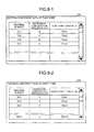
- FIG. 8-1 is a diagram illustrating an example of the information of the existing component of the tube yoke.
- FIG. 8-2 is a diagram illustrating an example of the information of the existing component of the shaft yoke.
- an existing component database 320 stores existing component data of a tube yoke which is designed already, and stores, for example, information of a drawing number, an extension-contraction specification, and a tube yoke length Tw which are correlated with each other in the internal storage device 4f or the external storage device 5.
- the existing component database 330 stores an existing component data of a shaft yoke which is designed already, and for example, stores information of a drawing number, an extension-contraction specification, and a shaft yoke length Sw which are correlated with each other in the internal storage device 4f or the external storage device 5.
- FIG. 8-3 is a diagram illustrating an example of the candidate component of the tube yoke.
- the drawing numbers TY1, TY2, TY3, and TY4 which are extracted as the candidate components are displayed as a candidate component list 325 on the display screen 321 together with the extension-contraction specification and the tube yoke length Tw.
- FIG. 8-4 is a diagram illustrating an example of the candidate component of the shaft yoke.
- the drawing numbers SY1 to SY7 which are extracted as the candidate component are displayed as the candidate component list 335 on the display screen 331 together with the extension-contraction specification and the tube yoke length Tw.
- control device 4 may extract the candidate component of the tube yoke and the candidate component of the shaft yoke included in the joint length acquired in step S101 from the information of the existing component using the CPU 4c and the existing component databases 320 and 330 as a candidate component extraction unit.
- the control device 4 displays the candidate component extracted in step S103 on the display device 3 (step S104).
- the control device 4 may assist the designer to select the candidate component by displaying the candidate component list 321 or the candidate component list 331 on the screen.
- FIG. 9 is a diagram illustrating an example of the input unit. For example, the designer selects the candidate component from the screen of displaying the candidate component list 321 or the candidate component list 331 by a keyboard 201 as an input unit of the input device 2.
- the control device 4 allocates an up cursor key 211 and a down cursor key 221 in the keyboard 201 illustrated in FIG. 9 as an input unit which is used to select the candidate component 323 or the candidate component 333 from the candidate component list 325 or the candidate component list 335.
- the control device 4 allocates a left cursor key 231 and a right cursor key 241 in the keyboard 201 illustrated in FIG. 9 as an input unit which is used to select the candidate component 323 or the candidate component 333 from the candidate component list 325 or the candidate component list 335.
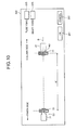
- FIG. 10 is a diagram illustrating an example of the initial screen of the output display screen.
- the control device 4 displays an output display screen 340 illustrated in FIG. 10 on the display device 3.
- the output display screen 340 displays the connection reference point HJ and the connection reference point GJ. For this reason, the designer may intuitively recognize the joint length W on the output display screen 340.
- the control device 4 may receive the information which is determined by the designer through the input interface 4a. Further, when the designer selects a process stop button 252 through a mouse or a keyboard as the input device 2, the control device 4 may receive an instruction for stopping the process of the control device 4 according to the intension of the designer through the input interface 4a. It is desirable that the output display screen 340 includes a tube yoke drawing number display section 253 and a shaft yoke drawing number display section 254. Accordingly, the designer may recognize the drawing number of the candidate component 323 or the candidate component 333 selected from the candidate component list 325 or the candidate component list 335.
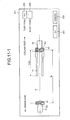
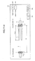
- FIGS. 11-1 to 11-4 are diagrams illustrating the output display screen which displays an example of the candidate component of the tube yoke.
- the shape of the tube yoke 11 changes in synchronization with the display of the drawing numbers (the drawing numbers of the selected candidate components) TY1, TY2, TY3, and TY4 of the tube yoke drawing number display section 253. Further, the tube yoke length Tw of the tube yoke 11 changes to TYw1, TYw2, TYw3, and TYw4 in synchronization with the display of the drawing numbers TY1, TY2, TY3, and TY4 of the tube yoke drawing number display section 253. For this reason, the designer checks the tube yoke length Tw of the output display screen 344 from the output display screen 341, and hence easily determines the component to be selected.
- FIGS. 12-1 to 12-7 are diagrams illustrating the output display screen which displays an example of the candidate component of the shaft yoke.
- the shape of the shaft yoke 14 changes in synchronization with the display of the drawing numbers (the drawing numbers of the selected candidate components) SY1, SY2, SY4, SY5, SY6, and SY7 of the display of the shaft yoke drawing number display section 254.
- the shaft yoke length Sw of the shaft yoke 14 changes to SYw1, SYw2, SYw3, SYw4, SYw4, SYw5, SYw6, and Sw7 in synchronization with the drawing numbers SY1, SY2, SY4, SY5, SY6, and SY7 of the shaft yoke drawing number display section 254.
- the shaft yoke fitting portion length Swj changes to SYwj1, SYwj2, SYwj3, SYwj4, SYwj4, SYwj5, SYwj6, and SYwj7 in synchronization with the display of the drawing numbers SY1, SY2, SY4, SY5, SY6, and SY7 of the shaft yoke drawing number display section 254. For this reason, the designer checks the shaft yoke length Sw of the output display screen 357 from the output display screen 351, and hence easily determines the component to be selected.
- the control device 4 may assist the determination of the designer who selects the candidate component in any one of the tube yoke 11 and the shaft yoke 14.
- the control device 4 does not store the selected component in the internal storage device 4f or the external storage device 5.
- the control device 4 advances the process to step S106.
- step S106 when there is another component to be selected (Yes in step S106), the control device 4 returns the process to step S104, and displays the screen of the candidate component.
- the process advances to step S107.
- the control device 4 displays a screen of a design instruction for prompting a design of a new component on the display device 3 (step S107).
- step S105 when there is an input of the select button 251 from the designer who inputs the select button 251 through the input device 2 such as a mouse or a keyboard (Yes in step S105), the control device 4 stores the selected component in the internal storage device 4f or the external storage device 5. Next, the control device 4 advances the process to step S111.
- control device 4 displays a screen of the candidate component of the corresponding component (step S111).
- the corresponding component is the shaft yoke.
- the corresponding component is the tube yoke.
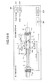
- the selected component is set as the tube yoke illustrated in FIG. 13-4 .
- the control device 4 displays the candidate component list 335 illustrated in FIG. 8-4 as the screen of the candidate component of the corresponding component.
- the designer operates the up cursor key 211 and the down cursor key 221 illustrated in FIG. 9 , and selects the candidate component 333 from the candidate component list 335.
- the control device 4 calls the drawing information of the candidate component 333 selected from the candidate component list 335 illustrated in FIG. 8-4 from the internal storage device 4f or the external storage device 5, and displays the drawing information so as to be superimposed on the output display screen 344 illustrated in FIG. 11-4 .
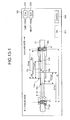
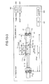
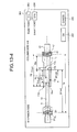
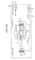
- FIGS. 13-1 to 13-7 are diagrams illustrating the output display screen which displays an example of the combination of the candidate components of the tube yoke and the shaft yoke.
- the shape of the shaft yoke 14 changes in synchronization with the drawing number of the shaft yoke drawing number display section 254. For this reason, the designer checks the fitting length JW from an output display screen 361 to an output display screen 367, and hence easily determines the component to be selected.
- the CPU 4c calculates the fitting length JW in which the candidate component of the tube yoke and the candidate component of the shaft yoke are combined with each other. Therefore, the CPU 4c executes a calculation in which the fitting length JW is compared with the fitting length specification acquired in step S102. Next, when the fitting length JW satisfies the fitting length specification (Yes in step S112), the CPU 4c calculates an instruction for storing the combination of the candidate component of the tube yoke and the candidate component of the shaft yoke in the internal storage device 4f or the external storage device 5 as the storage unit.
- the display device 3 displays the select button 251 as an index indicating the calculated instruction (step S114).
- the control device advances the process to step S115, so that it becomes a state where the input of the designer is awaited.
- step S115 When the designer selects the select button 251 through the input device 2 such as a mouse or a keyboard (Yes in step S115), the information of the combination of the candidate components based on the instruction is stored in the internal storage device 4f or the external storage device 5. Therefore, the control device 4 advances the process to step S116.
- the control device 4 returns the process to step S111, and the display device 3 displays the screen of the candidate component of the corresponding component.
- the fitting length JW in which the candidate component of the tube yoke and the candidate component of the shaft yoke are combined with each other satisfies the fitting length specification (No in step S112), the CPU 4c does not calculate an instruction for storing the combination of the candidate component of the tube yoke and the candidate component of the shaft yoke in the internal storage device 4f or the external storage device 5 as the storage unit.
- the display device 3 does not display the select button 251 as an index, and advances the process to step S113.
- step S113 when there is another component to be selected (Yes in step S113), the control device 4 returns the process to step S111, and displays the screen of the candidate component of the corresponding component.
- step S107 the control device 4 displays a screen of a design instruction for satisfying a design of a new component on the display device 3 (step S107).
- the CPU 4c does not calculate an instruction for storing the combination of the candidate component of the tube yoke and the candidate component of the shaft yoke in the internal storage device 4f or the external storage device 5. For this reason, it becomes a state where an instruction for storing the combination of the candidate components of the tube yoke and the shaft yoke illustrated in FIG. 13-1 in the internal storage device 4f or the external storage device 5. Therefore, the display device 3 does not display the select button 251 of the output display screen 361. Accordingly, since the designer may not select any combination, it is possible to prevent the combination of the candidate components of the tube yoke and the shaft yoke which may influence a bending strength or cause a backlash.
- the CPU 4c calculates an instruction for storing the combination of the candidate component of the tube yoke and the candidate component of the shaft yoke in the internal storage device 4f or the external storage device 5.
- the display device 3 displays the select button 251 on the output display screens 362, 363, 364, and 365. Accordingly, since the designer selects the select button 251, it is possible to select the combination of the candidate components of the tube yoke and the shaft yoke which does not influence a bending strength and inhibits a backlash.
- the control device 4 displays the select button 251 so that the control device 4 may store the combination of the candidate components of the tube yoke and the shaft yoke even when the positions of the tube yoke fitting leading end portion 11a and the shaft yoke fitting leading end portion 14a do not match each other as illustrated in, for example, FIGS. 13-3 , 13-4 , or 13-5 . That is, the control device 4 permits a state where a distance Rj between the tube yoke fitting leading end portion 11a and the shaft yoke fitting tail end portion 14b is longer than the fitting length JW.
- control device 4 sets the substantial fitting length between the tube yoke fitting portion 11j and the shaft yoke fitting portion 14j as the fitting length JW, and compares the fitting length with the fitting length acquired in step S102. For this reason, the combination of the candidate components of the tube yoke and the shaft yoke increases by a degree in which the positions of the tube yoke fitting leading end portion 11a and the shaft yoke fitting leading end portion 14a do not match each other. As a result, the frequency of use of the existing component increases, and hence the number of the production components to be managed may be decreased.
- the CPU 4c calculates the collision contraction length Rw in which the candidate component of the tube yoke and the candidate component of the shaft yoke are combined with each other. It is desirable that the CPU 4c executes a calculation of comparing the collision contraction length Rw with the information of the collision contraction length specification stored in the external storage device 5 or the internal storage device 4f. Accordingly, when the collision contraction length Rw is smaller than the information of the collision contraction length specification, that is, the collision contraction length Rw does not satisfy the collision contraction length specification, the control device 4 does not display the select button 251 so as not to store the combination of the candidate components of the tube yoke and the shaft yoke, for example, illustrated in FIGS. 13-6 and 13-7 .
- the collision contraction length Rw does not satisfy the collision contraction length specification even in the case of the fitting length JW satisfying the fitting length specification acquired in step S102.
- the CPU 4c does not calculate an instruction for storing the combination of the candidate component of the tube yoke and the candidate component of the shaft yoke in the internal storage device 4f or the external storage device 5. Therefore, the display device 3 does not display the select button 251 as an index indicating the presence of the instruction, and advances the process to step S113. Accordingly, since the designer does not select the select button 251, it is possible to prevent the selection of the combination of the candidate components of the tube yoke and the shaft yoke which may cause the insufficient collision contraction length.
- step S113 when there is another component to be selected (Yes in step S113), the control device 4 returns the process to step S111, and displays the screen of the candidate component of the corresponding component. Where there is not another component to be selected (No in step S113), the process is advanced to step S107.
- the control device 4 displays a screen of a design instruction satisfying a design of a new component on the display device 3 (step S107).
- control device 4 when the control device 4 receives an input by the selection of the designer select button 251 (Yes in step S115) in a state where the input of the designer is awaited (step S115), the control device 4 stores the combination of the candidate components in the internal storage device 4f or the external storage device 5 based on the instruction synchronized with the input signal from the display device 3. Next, the control device 4 advances the process to step S116.
- the control device 4 displays the drawing information of the combination of the candidate components of the tube yoke and the shaft yoke in the display device 3 in a three-dimensional space (step S114).
- the display device 3 disposes the candidate components of the tube yoke and the shaft yoke in a three-dimensional space in which the longitudinal direction, the vertical direction, and the transverse direction of the vehicle equipped with the steering device are defined as illustrated in FIG. 3 . Accordingly, the designer may three-dimensionally recognize of the combination of the candidate components of the tube yoke and the shaft yoke.
- the designer may rotate the intermediate shaft module 10 about the axis S on the display screen of the three-dimensional CAD, and finally check a proper state of the combination of the candidate components in consideration of the interference between the candidate components or the interference of the components disposed around the intermediate shaft module 10.
- the control device 4 ends the process.
- FIG. 14 is a diagram illustrating an example of the output display screen which displays a calculation result of the collision contraction length.
- the control device 4 may display the calculation result of the collision contraction length Rw and the fitting length JW as a result display 255 obtained by the combination of the candidate components of the tube yoke and the shaft yoke other than the select button 251 and the process stop button 252.
- the control device 4 displays the calculation result of the collision contraction length Rw on a collision contraction length display section 256.
- the control device 4 displays a calculation result of the fitting length JW on a fitting length display section 257. Accordingly, the designer may easily recognize the collision contraction length Rw and the fitting length JW in synchronization with the combination of the candidate components of the tube yoke and the shaft yoke.
- the control device 4 displays the calculation result of the fitting length JW on the fitting length display section 257, and for example, the cell of the fitting length display section 257 is highlighted in red. Further, when the collision contraction length Rw satisfies the condition of the collision contraction length, the control device 4 displays the calculation result of the collision contraction length Rw in the collision contraction length display section 256, and for example, the cell of the collision contraction length display section 256 is highlighted in red. Accordingly, the designer may understand whether the reason why the control device 4 does not display the select button 251 is caused by the fitting length JW which does not satisfy the fitting length specification, the collision contraction length Rw which does not satisfy the collision contraction length specification, or both reasons.
- the design assistance device for the steering device may assist the selection of the combination of the candidate component of the tube yoke and the candidate component of the shaft yoke which uses the existing components of the tube yoke and the shaft yoke as much as possible.
- the control device 4 displays the select button 251 on the display device 3.
- the storage unit may store the combination of the candidate component of the tube yoke and the candidate component of the shaft yoke which is selected by the designer. Accordingly, the designer may select the combination of the candidate component of the tube yoke and the candidate component of the shaft yoke appropriate for the conditions of the joint length and the fitting length from the existing components in which the number of the tube yokes and the shaft yokes is large.
- the control device 4 When the fitting length JW in which the candidate component of the tube yoke and the candidate component of the shaft yoke are combined with each other does not satisfy the condition of the fitting length, the control device 4 does not display the select button 251 on the display device 3. Since the select button 251 may not be selected, the control device 4 may not receive the information which determines the drawing selected by the designer. Accordingly, since the designer may not select any combination, it is possible to prevent the combination of the candidate components of the tube yoke and the shaft yoke which may influence a bending strength or cause a backlash.
- the control device 4 When the fitting length JW in which the candidate component of the tube yoke and the candidate component of the shaft yoke are combined with each other satisfies the condition of the fitting length but the collision contraction length Rw is smaller than the information of the condition of the collision contraction length stored in the external storage device 5 or the internal storage device 4f, the control device 4 does not display the select button 251 on the display device 3. Since the select button 251 is not selected, the control device 4 may not receive the information which determines the drawing selected by the designer. Accordingly, it is possible to prevent the selection of the combination of the candidate components of the tube yoke and the shaft yoke which may cause the insufficient collision contraction length.
- FIG. 15 is a flowchart illustrating a procedure of a process of a design assistance device for a steering device according to Second Embodiment.
- the control device 4 acquires priority rank information such as cost, and determines the prioritized combination of the candidate components of the tube yoke and the shaft yoke based on the priority rank information. Further, the same reference numerals will be given to the same components as those of the above-described embodiment, and the description thereof will not be repeated.
- step S201, step S202, step S203, step S204, step S205, step S206, step S207, step S211, step S212, step S213, and step S214 respectively have the same process procedures as those of step S101, step S102, step S103, step S104, step S105, step S106, step S107, step S111, step S112, step S113, and step S114, the detailed description thereof will not be repeated.
- the CPU 4c calculates an instruction for storing the combination of the candidate component of the tube yoke and the candidate component of the shaft yoke in the internal storage device 4f or the external storage device 5.
- the display device 3 displays the select button 251 which is an index indicating the presence of the instruction (step S214).
- the control device advances the process to step S215, so that it becomes a state where the input of the designer is awaited.
- step S215 When the designer does not select the select button 251 through the input device 2 such as a mouse or a keyboard (No in step S215), for example, when the process is stopped by the process stop button 252, the control device 4 returns the process to step S204, and the display device 3 displays the screen of the candidate component.
- the input device 2 such as a mouse or a keyboard
- control device 4 when the control device 4 receives an input by the selection of the designer select button 251 (Yes in step S215) in a state where the input of the designer is awaited (step S215), the control device 4 stores the combination of the candidate components in the internal storage device 4f or the external storage device 5 based on the instruction synchronized with the input signal from the display device 3.
- FIG. 16 is a diagram illustrating an example of a data table of the combination of the candidate components of the tube yoke and the shaft yoke.
- the control device 4 stores the combination of the candidate components as a circular mark (o) like, for example, a data table 411 illustrated in FIG. 16 .
- the control device 4 does not store the selected component in the internal storage device 4f or the external storage device 5 (No in step S212).
- the control device 4 advances the process to step S204, and stores the case as a cross mark (x) in a data table 411.
- the control device 4 sequentially decreases the number of blanks of the data table 411 by performing the process procedure.
- the control device 4 acquires priority rank information, for example, information of a priority rank to be selected first based on the cost of the candidate components of the tube yoke and the shaft yoke (step S216).
- FIG. 17-1 is a diagram illustrating an example of a cost data table of the candidate component of the tube yoke.
- FIG. 17-2 is a diagram illustrating an example of a cost data table the candidate component of the shaft yoke.
- the circular mark (o) is a component of which a distribution amount is large and cost decreases among the existing components.
- a triangular mark ( ⁇ ) is a component of which a distribution amount is present and cost is medium among the existing components.
- a cross mark (x) is a component of which a distribution amount is small and cost is expensive among the existing components.
- the control device 4 stores the data table 421 and the data table 431 as the priority rank information in the internal storage device 4f or the external storage device 5 in advance.
- step S216 the control device 4 performs a process of reading out the data table 421 and the data table 431 from the internal storage device 4f or the external storage device 5 to the RAM 4e, and advances the process to step S217.
- the CPU 4c of the control device 4 gives a selection rank of the candidate component to the combination of the candidate components stored in step S214 based on the priority rank information acquired in step S216 (step S217).
- the control device 4 applies the priority ranks of the data table 421 and the data table 431 to the data table 411.
- FIG. 18 is a diagram illustrating an example of a rank data table which shows a priority rank of a combination of the candidate components of the tube yoke and the shaft yoke.
- the control device 4 sets the combination of the circular mark (o) of the data table 421 and the circular mark (o) of the data table 431 as a rank "1".
- the control device 4 sets the combination including the circular mark (o) of the data table 421 (o) or the circular mark (o) of the data table 431 and including the triangular mark ( ⁇ ) of the data table 421 or the triangular mark ( ⁇ ) of the data table 431 as a rank "2".
- control device 4 sets the combination including the triangular mark ( ⁇ ) of the data table 421 and the triangular mark ( ⁇ ) of the data table 431 as a rank "3".
- the control device 4 sets the combination including the circular mark (o) of the data table 421 or the circular mark (o) of the data table 431 and the cross mark (x) of the data table 421 or the cross mark (x) of the data table 431 as a rank "4".
- control device 4 sets the combination of the cross mark ( ⁇ ) of the data table 421 and the cross mark ( ⁇ ) of the data table 431 as a rank "5". Further, in the data table 441, the crossbar (-) is the combination in which the combination of the candidate components of the tube yoke and the shaft yoke is not established in the data table 411.
- the control device 4 determines the combination of the prioritized components from the combinations of the candidate components of the tube yoke and the shaft yoke of which the number is the smallest in the data table 441. For example, the control device 4 determines the combination of the components in which the combination of the candidate component of the drawing number TY4 of the tube yoke and the candidate component of the drawing number SY4 of the shaft yoke in FIG. 18 is prioritized. By the above-described procedure, the control device 4 ends the process.
- the design assistance device for the steering device may assist the selection of the combination in which a condition such as cost is better among the candidate components.
- the design assistance device for the steering device may assist the selection of the combination in which a condition such as a weight or a layout is better among the candidate components.
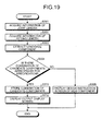
- FIG. 19 is a flowchart illustrating a procedure of a process of a design assistance device for a steering device according to Third Embodiment.
- the control device 4 stores the combination of the candidate components of the tube yoke and the shaft yoke, and displays the output display screen of the candidate components. Further, the same reference numerals will be given to the same components as those of the above-described embodiment, and the description thereof will not be repeated.
- step S301, step S302, and step S303 respectively have the same process procedures as those of step S101, step S102, and step S103 of First Embodiment, the detailed description thereof will not be repeated.
- the control device 4 calculates the combination of the candidate components appropriate for the specification in which the candidate component extracted in step S303 satisfies the joint length acquired in step S301, the fitting length specification acquired in step S302, and the collision contraction length specification stored in the external storage device 5 or the internal storage device 4f.
- the process is advanced to step S305.
- the control device 4 displays a screen of a design instruction for prompting a design of a new component on the display device 3 (step S305).
- the process is advanced to step S311.
- control device 4 stores all combinations of the candidate components appropriate for the specification as the circular mark (o) like the data table 411 illustrated in FIG. 16 (step S311). Therefore, the control device 4 advances the process to step S312.
- control device 4 displays the output display screen of the combination of the appropriate candidate components of the circular mark (o) of the data table 411 stored in step S311 and illustrated in FIG. 16 , for example, the output display screen 362 to the output display screen 365 illustrated in FIGS. 13-2 to FIG. 13-5 on the display device 3. Accordingly, the designer may efficiently check the output display screen 362 to the output display screen 365 which are appropriate for the specification.
- FIG. 20 is a flowchart illustrating a procedure of a process of a design assistance device for a steering device according to Fourth Embodiment.
- the control device 4 stores the combination of the candidate components of the tube yoke and the shaft yoke, and displays the output display screen of the prioritized candidate component and the appropriate candidate component. Further, the same reference numerals will be given to the same components as those of the above-described embodiment, and the description thereof will not be repeated.
- step S401, step S402, and step S403 respectively have the same process procedures as those of step S101, step S102, and step S103 of First Embodiment, the detailed description thereof will not be repeated. Further, since step S404, step S405, and step S411 respectively have the same process procedures as those of step S304, step S1305, and step S311 of Third Embodiment, the detailed description thereof will not be repeated.
- the CPU 4c of the control device 4 acquires priority rank information, for example, information of a priority rank to be selected first based on the cost of the candidate components of the tube yoke and the shaft yoke (step S412). This procedure is the same as that of the process of step S216 described in Second Embodiment.
- control device 4 sequences the combinations of the candidate components stored in step S411 based on the priority rank information acquired in step S412, and determines the combination of the prioritized components (step S413). This procedure is the same as that of the process procedure of step S214 described in Second Embodiment.
- the control device 4 determines the combination of the prioritized candidate components from the combinations of the candidate components of the tube yoke and the shaft yoke of which the number is the smallest in the data table 441.
- control device 4 displays the output display screen of the combination of the prioritized candidate component determined in step S413, for example, an output display screen 364 illustrated in FIG. 13-4 on the display device 3 (step S414). Accordingly, the designer may efficiently check the output display screen 364 which displays the combination of the candidate components appropriate for the specification and having a high priority.
Landscapes
- Engineering & Computer Science (AREA)
- Physics & Mathematics (AREA)
- Geometry (AREA)
- Theoretical Computer Science (AREA)
- General Physics & Mathematics (AREA)
- Mechanical Engineering (AREA)
- Transportation (AREA)
- Combustion & Propulsion (AREA)
- Chemical & Material Sciences (AREA)
- Mathematical Optimization (AREA)
- General Engineering & Computer Science (AREA)
- Evolutionary Computation (AREA)
- Computer Hardware Design (AREA)
- Pure & Applied Mathematics (AREA)
- Mathematical Analysis (AREA)
- Computational Mathematics (AREA)
- Automation & Control Theory (AREA)
- Aviation & Aerospace Engineering (AREA)
- Steering Controls (AREA)
- Power Steering Mechanism (AREA)
Applications Claiming Priority (2)
| Application Number | Priority Date | Filing Date | Title |
|---|---|---|---|
| JP2011186469A JP5794040B2 (ja) | 2011-08-29 | 2011-08-29 | ステアリング装置の設計支援装置及びステアリング装置設計支援方法 |
| PCT/JP2012/065730 WO2013031347A1 (ja) | 2011-08-29 | 2012-06-20 | ステアリング装置の設計支援装置及びステアリング装置設計支援方法 |
Publications (3)
| Publication Number | Publication Date |
|---|---|
| EP2762384A1 true EP2762384A1 (de) | 2014-08-06 |
| EP2762384A4 EP2762384A4 (de) | 2015-07-08 |
| EP2762384B1 EP2762384B1 (de) | 2019-02-27 |
Family
ID=47755859
Family Applications (1)
| Application Number | Title | Priority Date | Filing Date |
|---|---|---|---|
| EP12813248.7A Not-in-force EP2762384B1 (de) | 2011-08-29 | 2012-06-20 | Hilfsvorrichtung für den entwurf einer lenkvorrichtung und hilfsverfahren für den entwurf einer lenkvorrichtung |
Country Status (5)
| Country | Link |
|---|---|
| US (1) | US9519748B2 (de) |
| EP (1) | EP2762384B1 (de) |
| JP (1) | JP5794040B2 (de) |
| CN (1) | CN103097228B (de) |
| WO (1) | WO2013031347A1 (de) |
Families Citing this family (2)
| Publication number | Priority date | Publication date | Assignee | Title |
|---|---|---|---|---|
| CN104598668B (zh) * | 2014-12-11 | 2017-08-25 | 华晨汽车集团控股有限公司 | 一种汽车转向系统模态模型的建模方法 |
| US20210342500A1 (en) * | 2020-05-01 | 2021-11-04 | Steering Solutions Ip Holding Corporation | Systems and methods for vehicle modeling |
Family Cites Families (19)
| Publication number | Priority date | Publication date | Assignee | Title |
|---|---|---|---|---|
| JPH07105244A (ja) * | 1993-09-30 | 1995-04-21 | Mazda Motor Corp | 設計手順支援装置 |
| JPH07200659A (ja) * | 1993-12-29 | 1995-08-04 | Mazda Motor Corp | 配置設計支援装置 |
| US5560650A (en) * | 1995-07-24 | 1996-10-01 | General Motors Corporation | Intermediate steering shaft |
| JPH11238069A (ja) | 1998-02-20 | 1999-08-31 | Fuji Electric Co Ltd | 部品選定装置 |
| JP2003170839A (ja) | 2001-12-04 | 2003-06-17 | Toyoda Mach Works Ltd | ステアリング装置用衝撃吸収装置 |
| JP4019918B2 (ja) * | 2002-11-28 | 2007-12-12 | 日本精工株式会社 | 電動パワーステアリング装置の統合設計システム |
| JP4190905B2 (ja) * | 2003-02-06 | 2008-12-03 | 日本精工株式会社 | 車両用ステアリング装置 |
| JP4399724B2 (ja) * | 2004-07-28 | 2010-01-20 | 株式会社ジェイテクト | ステアリングシャフト |
| JP5119707B2 (ja) * | 2006-06-29 | 2013-01-16 | 日本精工株式会社 | 伸縮軸 |
| JP2008117031A (ja) * | 2006-11-01 | 2008-05-22 | Fujitsu Ltd | 設計支援装置,設計支援方法,設計支援プログラムおよびcadシステム |
| JP2008197899A (ja) * | 2007-02-13 | 2008-08-28 | Nsk Ltd | 電動パワーステアリングシステムの設計システム及び電動パワーステアリングシステム |
| JP2008208865A (ja) * | 2007-02-23 | 2008-09-11 | Jtekt Corp | 軸継手およびステアリング装置 |
| JP2008269080A (ja) * | 2007-04-17 | 2008-11-06 | Nsk Ltd | 電動パワーステアリング装置の制御装置の設計支援装置及び電動パワーステアリング装置の制御装置 |
| JP2009006956A (ja) * | 2007-06-29 | 2009-01-15 | Jtekt Corp | 衝撃吸収式車両用操舵装置 |
| JP2009006955A (ja) * | 2007-06-29 | 2009-01-15 | Jtekt Corp | 衝撃吸収式車両用操舵装置 |
| JP2009301410A (ja) * | 2008-06-16 | 2009-12-24 | Nissan Motor Co Ltd | 設計支援システムおよびコンピュータ・プログラム |
| JP2010181937A (ja) * | 2009-02-03 | 2010-08-19 | Nissan Motor Co Ltd | 設計支援システム及び設計支援方法 |
| JP2011216024A (ja) * | 2010-04-01 | 2011-10-27 | Nsk Ltd | 3次元モデル組立支援方法及びシステム |
| US8965743B2 (en) | 2010-10-06 | 2015-02-24 | Nsk Ltd. | Steering device design assisting apparatus and steering device design assisting method |
-
2011
- 2011-08-29 JP JP2011186469A patent/JP5794040B2/ja active Active
-
2012
- 2012-06-20 EP EP12813248.7A patent/EP2762384B1/de not_active Not-in-force
- 2012-06-20 CN CN201280000681.0A patent/CN103097228B/zh not_active Expired - Fee Related
- 2012-06-20 WO PCT/JP2012/065730 patent/WO2013031347A1/ja not_active Ceased
- 2012-06-20 US US13/812,084 patent/US9519748B2/en active Active
Also Published As
| Publication number | Publication date |
|---|---|
| EP2762384B1 (de) | 2019-02-27 |
| CN103097228B (zh) | 2015-07-08 |
| US9519748B2 (en) | 2016-12-13 |
| EP2762384A4 (de) | 2015-07-08 |
| WO2013031347A1 (ja) | 2013-03-07 |
| JP2013047071A (ja) | 2013-03-07 |
| JP5794040B2 (ja) | 2015-10-14 |
| CN103097228A (zh) | 2013-05-08 |
| US20140195204A1 (en) | 2014-07-10 |
Similar Documents
| Publication | Publication Date | Title |
|---|---|---|
| JP5660073B2 (ja) | 駐車支援装置、駐車支援方法、及び駐車支援プログラム | |
| US20160362117A1 (en) | Retractable handwheel gesture control | |
| US7969290B2 (en) | Information device, preferably in a motor vehicle, and method for supplying information about vehicle data, in particular vehicle functions and their operation | |
| EP2626799B1 (de) | Designhilfsvorrichtung für eine lenkvorrichtung und verfahren zur unterstützung des entwurfs einer lenkvorrichtung | |
| CN119137447A (zh) | 用于向休闲车辆的操作者呈现信息的系统和方法 | |
| JP6389006B2 (ja) | 自動車の少なくとも1つの走行機能の自動化された実施のための方法 | |
| KR102082555B1 (ko) | 목록에서 객체를 선택하기 위한 방법 및 장치 | |
| EP2762384B1 (de) | Hilfsvorrichtung für den entwurf einer lenkvorrichtung und hilfsverfahren für den entwurf einer lenkvorrichtung | |
| US11059486B2 (en) | Vehicle control unit, vehicle, and vehicle control method | |
| JP4682809B2 (ja) | 駐車支援システム | |
| JP6512174B2 (ja) | 車載警告システム | |
| CN103895688A (zh) | 具有倾斜和伸缩功能的转向装置 | |
| Pickering et al. | A review of automotive human machine interface technologies and techniques to reduce driver distraction | |
| EP2608077A1 (de) | Kollektion von Dokumenten für eine panoptisches Visualisierung | |
| JP2024055756A (ja) | 駐車経路を決定する装置及び方法 | |
| JP5971381B2 (ja) | ステアリング装置の設計支援装置及びステアリング装置設計支援方法 | |
| JP5451665B2 (ja) | 文字入力装置、文字入力方法、及びプログラム | |
| CN108228937A (zh) | 一种基于cae的转向系统机构仿真方法 | |
| US12573210B2 (en) | Parking assistance device | |
| CN116560529A (zh) | 用户界面的操作方法及系统、存储介质、电子装置 | |
| US20200324815A1 (en) | Smart controller | |
| Summerskill et al. | Bionic–“Eyes-Free” Design of Secondary Driving Controls | |
| JP6681604B2 (ja) | 運転支援装置、運転支援システム、運転支援方法、運転支援プログラム及び自動運転車両 | |
| JP2015013511A (ja) | 車両用入力支援装置 | |
| US12275304B2 (en) | Image display control device, image display control method, and computer-readable storage medium |
Legal Events
| Date | Code | Title | Description |
|---|---|---|---|
| PUAI | Public reference made under article 153(3) epc to a published international application that has entered the european phase |
Free format text: ORIGINAL CODE: 0009012 |
|
| 17P | Request for examination filed |
Effective date: 20130124 |
|
| AK | Designated contracting states |
Kind code of ref document: A1 Designated state(s): AL AT BE BG CH CY CZ DE DK EE ES FI FR GB GR HR HU IE IS IT LI LT LU LV MC MK MT NL NO PL PT RO RS SE SI SK SM TR |
|
| DAX | Request for extension of the european patent (deleted) | ||
| RA4 | Supplementary search report drawn up and despatched (corrected) |
Effective date: 20150610 |
|
| RIC1 | Information provided on ipc code assigned before grant |
Ipc: G06F 17/50 20060101ALI20150603BHEP Ipc: B62D 1/16 20060101AFI20150603BHEP Ipc: B62D 1/20 20060101ALN20150603BHEP Ipc: B62D 5/04 20060101ALI20150603BHEP |
|
| GRAP | Despatch of communication of intention to grant a patent |
Free format text: ORIGINAL CODE: EPIDOSNIGR1 |
|
| STAA | Information on the status of an ep patent application or granted ep patent |
Free format text: STATUS: GRANT OF PATENT IS INTENDED |
|
| RIC1 | Information provided on ipc code assigned before grant |
Ipc: G06F 17/50 20060101ALI20180905BHEP Ipc: B62D 1/16 20060101AFI20180905BHEP Ipc: B62D 5/04 20060101ALI20180905BHEP Ipc: B62D 1/20 20060101ALN20180905BHEP |
|
| INTG | Intention to grant announced |
Effective date: 20180925 |
|
| GRAS | Grant fee paid |
Free format text: ORIGINAL CODE: EPIDOSNIGR3 |
|
| GRAA | (expected) grant |
Free format text: ORIGINAL CODE: 0009210 |
|
| STAA | Information on the status of an ep patent application or granted ep patent |
Free format text: STATUS: THE PATENT HAS BEEN GRANTED |
|
| AK | Designated contracting states |
Kind code of ref document: B1 Designated state(s): AL AT BE BG CH CY CZ DE DK EE ES FI FR GB GR HR HU IE IS IT LI LT LU LV MC MK MT NL NO PL PT RO RS SE SI SK SM TR |
|
| REG | Reference to a national code |
Ref country code: GB Ref legal event code: FG4D |
|
| REG | Reference to a national code |
Ref country code: CH Ref legal event code: EP |
|
| REG | Reference to a national code |
Ref country code: AT Ref legal event code: REF Ref document number: 1100897 Country of ref document: AT Kind code of ref document: T Effective date: 20190315 |
|
| REG | Reference to a national code |
Ref country code: IE Ref legal event code: FG4D |
|
| REG | Reference to a national code |
Ref country code: DE Ref legal event code: R096 Ref document number: 602012057216 Country of ref document: DE |
|
| REG | Reference to a national code |
Ref country code: NL Ref legal event code: MP Effective date: 20190227 |
|
| REG | Reference to a national code |
Ref country code: LT Ref legal event code: MG4D |
|
| PG25 | Lapsed in a contracting state [announced via postgrant information from national office to epo] |
Ref country code: NL Free format text: LAPSE BECAUSE OF FAILURE TO SUBMIT A TRANSLATION OF THE DESCRIPTION OR TO PAY THE FEE WITHIN THE PRESCRIBED TIME-LIMIT Effective date: 20190227 Ref country code: LT Free format text: LAPSE BECAUSE OF FAILURE TO SUBMIT A TRANSLATION OF THE DESCRIPTION OR TO PAY THE FEE WITHIN THE PRESCRIBED TIME-LIMIT Effective date: 20190227 Ref country code: FI Free format text: LAPSE BECAUSE OF FAILURE TO SUBMIT A TRANSLATION OF THE DESCRIPTION OR TO PAY THE FEE WITHIN THE PRESCRIBED TIME-LIMIT Effective date: 20190227 Ref country code: NO Free format text: LAPSE BECAUSE OF FAILURE TO SUBMIT A TRANSLATION OF THE DESCRIPTION OR TO PAY THE FEE WITHIN THE PRESCRIBED TIME-LIMIT Effective date: 20190527 Ref country code: PT Free format text: LAPSE BECAUSE OF FAILURE TO SUBMIT A TRANSLATION OF THE DESCRIPTION OR TO PAY THE FEE WITHIN THE PRESCRIBED TIME-LIMIT Effective date: 20190627 Ref country code: SE Free format text: LAPSE BECAUSE OF FAILURE TO SUBMIT A TRANSLATION OF THE DESCRIPTION OR TO PAY THE FEE WITHIN THE PRESCRIBED TIME-LIMIT Effective date: 20190227 |
|
| PG25 | Lapsed in a contracting state [announced via postgrant information from national office to epo] |
Ref country code: GR Free format text: LAPSE BECAUSE OF FAILURE TO SUBMIT A TRANSLATION OF THE DESCRIPTION OR TO PAY THE FEE WITHIN THE PRESCRIBED TIME-LIMIT Effective date: 20190528 Ref country code: BG Free format text: LAPSE BECAUSE OF FAILURE TO SUBMIT A TRANSLATION OF THE DESCRIPTION OR TO PAY THE FEE WITHIN THE PRESCRIBED TIME-LIMIT Effective date: 20190527 Ref country code: HR Free format text: LAPSE BECAUSE OF FAILURE TO SUBMIT A TRANSLATION OF THE DESCRIPTION OR TO PAY THE FEE WITHIN THE PRESCRIBED TIME-LIMIT Effective date: 20190227 Ref country code: IS Free format text: LAPSE BECAUSE OF FAILURE TO SUBMIT A TRANSLATION OF THE DESCRIPTION OR TO PAY THE FEE WITHIN THE PRESCRIBED TIME-LIMIT Effective date: 20190627 Ref country code: RS Free format text: LAPSE BECAUSE OF FAILURE TO SUBMIT A TRANSLATION OF THE DESCRIPTION OR TO PAY THE FEE WITHIN THE PRESCRIBED TIME-LIMIT Effective date: 20190227 Ref country code: LV Free format text: LAPSE BECAUSE OF FAILURE TO SUBMIT A TRANSLATION OF THE DESCRIPTION OR TO PAY THE FEE WITHIN THE PRESCRIBED TIME-LIMIT Effective date: 20190227 |
|
| PGFP | Annual fee paid to national office [announced via postgrant information from national office to epo] |
Ref country code: FR Payment date: 20190510 Year of fee payment: 8 |
|
| REG | Reference to a national code |
Ref country code: AT Ref legal event code: MK05 Ref document number: 1100897 Country of ref document: AT Kind code of ref document: T Effective date: 20190227 |
|
| PG25 | Lapsed in a contracting state [announced via postgrant information from national office to epo] |
Ref country code: SK Free format text: LAPSE BECAUSE OF FAILURE TO SUBMIT A TRANSLATION OF THE DESCRIPTION OR TO PAY THE FEE WITHIN THE PRESCRIBED TIME-LIMIT Effective date: 20190227 Ref country code: CZ Free format text: LAPSE BECAUSE OF FAILURE TO SUBMIT A TRANSLATION OF THE DESCRIPTION OR TO PAY THE FEE WITHIN THE PRESCRIBED TIME-LIMIT Effective date: 20190227 Ref country code: RO Free format text: LAPSE BECAUSE OF FAILURE TO SUBMIT A TRANSLATION OF THE DESCRIPTION OR TO PAY THE FEE WITHIN THE PRESCRIBED TIME-LIMIT Effective date: 20190227 Ref country code: ES Free format text: LAPSE BECAUSE OF FAILURE TO SUBMIT A TRANSLATION OF THE DESCRIPTION OR TO PAY THE FEE WITHIN THE PRESCRIBED TIME-LIMIT Effective date: 20190227 Ref country code: AL Free format text: LAPSE BECAUSE OF FAILURE TO SUBMIT A TRANSLATION OF THE DESCRIPTION OR TO PAY THE FEE WITHIN THE PRESCRIBED TIME-LIMIT Effective date: 20190227 Ref country code: EE Free format text: LAPSE BECAUSE OF FAILURE TO SUBMIT A TRANSLATION OF THE DESCRIPTION OR TO PAY THE FEE WITHIN THE PRESCRIBED TIME-LIMIT Effective date: 20190227 Ref country code: DK Free format text: LAPSE BECAUSE OF FAILURE TO SUBMIT A TRANSLATION OF THE DESCRIPTION OR TO PAY THE FEE WITHIN THE PRESCRIBED TIME-LIMIT Effective date: 20190227 Ref country code: IT Free format text: LAPSE BECAUSE OF FAILURE TO SUBMIT A TRANSLATION OF THE DESCRIPTION OR TO PAY THE FEE WITHIN THE PRESCRIBED TIME-LIMIT Effective date: 20190227 |
|
| PGFP | Annual fee paid to national office [announced via postgrant information from national office to epo] |
Ref country code: GB Payment date: 20190619 Year of fee payment: 8 |
|
| REG | Reference to a national code |
Ref country code: DE Ref legal event code: R097 Ref document number: 602012057216 Country of ref document: DE |
|
| PG25 | Lapsed in a contracting state [announced via postgrant information from national office to epo] |
Ref country code: SM Free format text: LAPSE BECAUSE OF FAILURE TO SUBMIT A TRANSLATION OF THE DESCRIPTION OR TO PAY THE FEE WITHIN THE PRESCRIBED TIME-LIMIT Effective date: 20190227 Ref country code: PL Free format text: LAPSE BECAUSE OF FAILURE TO SUBMIT A TRANSLATION OF THE DESCRIPTION OR TO PAY THE FEE WITHIN THE PRESCRIBED TIME-LIMIT Effective date: 20190227 |
|
| PG25 | Lapsed in a contracting state [announced via postgrant information from national office to epo] |
Ref country code: AT Free format text: LAPSE BECAUSE OF FAILURE TO SUBMIT A TRANSLATION OF THE DESCRIPTION OR TO PAY THE FEE WITHIN THE PRESCRIBED TIME-LIMIT Effective date: 20190227 |
|
| PLBE | No opposition filed within time limit |
Free format text: ORIGINAL CODE: 0009261 |
|
| STAA | Information on the status of an ep patent application or granted ep patent |
Free format text: STATUS: NO OPPOSITION FILED WITHIN TIME LIMIT |
|
| PG25 | Lapsed in a contracting state [announced via postgrant information from national office to epo] |
Ref country code: MC Free format text: LAPSE BECAUSE OF FAILURE TO SUBMIT A TRANSLATION OF THE DESCRIPTION OR TO PAY THE FEE WITHIN THE PRESCRIBED TIME-LIMIT Effective date: 20190227 |
|
| REG | Reference to a national code |
Ref country code: CH Ref legal event code: PL |
|
| 26N | No opposition filed |
Effective date: 20191128 |
|
| PG25 | Lapsed in a contracting state [announced via postgrant information from national office to epo] |
Ref country code: SI Free format text: LAPSE BECAUSE OF FAILURE TO SUBMIT A TRANSLATION OF THE DESCRIPTION OR TO PAY THE FEE WITHIN THE PRESCRIBED TIME-LIMIT Effective date: 20190227 |
|
| REG | Reference to a national code |
Ref country code: BE Ref legal event code: MM Effective date: 20190630 |
|
| PG25 | Lapsed in a contracting state [announced via postgrant information from national office to epo] |
Ref country code: TR Free format text: LAPSE BECAUSE OF FAILURE TO SUBMIT A TRANSLATION OF THE DESCRIPTION OR TO PAY THE FEE WITHIN THE PRESCRIBED TIME-LIMIT Effective date: 20190227 |
|
| PG25 | Lapsed in a contracting state [announced via postgrant information from national office to epo] |
Ref country code: IE Free format text: LAPSE BECAUSE OF NON-PAYMENT OF DUE FEES Effective date: 20190620 |
|
| PG25 | Lapsed in a contracting state [announced via postgrant information from national office to epo] |
Ref country code: LI Free format text: LAPSE BECAUSE OF NON-PAYMENT OF DUE FEES Effective date: 20190630 Ref country code: BE Free format text: LAPSE BECAUSE OF NON-PAYMENT OF DUE FEES Effective date: 20190630 Ref country code: CH Free format text: LAPSE BECAUSE OF NON-PAYMENT OF DUE FEES Effective date: 20190630 Ref country code: LU Free format text: LAPSE BECAUSE OF NON-PAYMENT OF DUE FEES Effective date: 20190620 |
|
| GBPC | Gb: european patent ceased through non-payment of renewal fee |
Effective date: 20200620 |
|
| PG25 | Lapsed in a contracting state [announced via postgrant information from national office to epo] |
Ref country code: FR Free format text: LAPSE BECAUSE OF NON-PAYMENT OF DUE FEES Effective date: 20200630 Ref country code: GB Free format text: LAPSE BECAUSE OF NON-PAYMENT OF DUE FEES Effective date: 20200620 |
|
| PG25 | Lapsed in a contracting state [announced via postgrant information from national office to epo] |
Ref country code: CY Free format text: LAPSE BECAUSE OF FAILURE TO SUBMIT A TRANSLATION OF THE DESCRIPTION OR TO PAY THE FEE WITHIN THE PRESCRIBED TIME-LIMIT Effective date: 20190227 |
|
| PG25 | Lapsed in a contracting state [announced via postgrant information from national office to epo] |
Ref country code: MT Free format text: LAPSE BECAUSE OF FAILURE TO SUBMIT A TRANSLATION OF THE DESCRIPTION OR TO PAY THE FEE WITHIN THE PRESCRIBED TIME-LIMIT Effective date: 20190227 Ref country code: HU Free format text: LAPSE BECAUSE OF FAILURE TO SUBMIT A TRANSLATION OF THE DESCRIPTION OR TO PAY THE FEE WITHIN THE PRESCRIBED TIME-LIMIT; INVALID AB INITIO Effective date: 20120620 |
|
| PG25 | Lapsed in a contracting state [announced via postgrant information from national office to epo] |
Ref country code: MK Free format text: LAPSE BECAUSE OF FAILURE TO SUBMIT A TRANSLATION OF THE DESCRIPTION OR TO PAY THE FEE WITHIN THE PRESCRIBED TIME-LIMIT Effective date: 20190227 |
|
| PGFP | Annual fee paid to national office [announced via postgrant information from national office to epo] |
Ref country code: DE Payment date: 20230502 Year of fee payment: 12 |
|
| REG | Reference to a national code |
Ref country code: DE Ref legal event code: R119 Ref document number: 602012057216 Country of ref document: DE |
|
| PG25 | Lapsed in a contracting state [announced via postgrant information from national office to epo] |
Ref country code: DE Free format text: LAPSE BECAUSE OF NON-PAYMENT OF DUE FEES Effective date: 20250101 |