EP2760210B1 - Method for displaying stereoscopic image and display apparatus for performing the same - Google Patents
Method for displaying stereoscopic image and display apparatus for performing the same Download PDFInfo
- Publication number
- EP2760210B1 EP2760210B1 EP14163783.5A EP14163783A EP2760210B1 EP 2760210 B1 EP2760210 B1 EP 2760210B1 EP 14163783 A EP14163783 A EP 14163783A EP 2760210 B1 EP2760210 B1 EP 2760210B1
- Authority
- EP
- European Patent Office
- Prior art keywords
- light
- emitting
- eye
- interval
- block
- Prior art date
- Legal status (The legal status is an assumption and is not a legal conclusion. Google has not performed a legal analysis and makes no representation as to the accuracy of the status listed.)
- Active
Links
Images







Classifications
-
- H—ELECTRICITY
- H04—ELECTRIC COMMUNICATION TECHNIQUE
- H04N—PICTORIAL COMMUNICATION, e.g. TELEVISION
- H04N13/00—Stereoscopic video systems; Multi-view video systems; Details thereof
- H04N13/30—Image reproducers
- H04N13/332—Displays for viewing with the aid of special glasses or head-mounted displays [HMD]
- H04N13/341—Displays for viewing with the aid of special glasses or head-mounted displays [HMD] using temporal multiplexing
-
- G—PHYSICS
- G09—EDUCATION; CRYPTOGRAPHY; DISPLAY; ADVERTISING; SEALS
- G09G—ARRANGEMENTS OR CIRCUITS FOR CONTROL OF INDICATING DEVICES USING STATIC MEANS TO PRESENT VARIABLE INFORMATION
- G09G3/00—Control arrangements or circuits, of interest only in connection with visual indicators other than cathode-ray tubes
- G09G3/001—Control arrangements or circuits, of interest only in connection with visual indicators other than cathode-ray tubes using specific devices not provided for in groups G09G3/02 - G09G3/36, e.g. using an intermediate record carrier such as a film slide; Projection systems; Display of non-alphanumerical information, solely or in combination with alphanumerical information, e.g. digital display on projected diapositive as background
- G09G3/003—Control arrangements or circuits, of interest only in connection with visual indicators other than cathode-ray tubes using specific devices not provided for in groups G09G3/02 - G09G3/36, e.g. using an intermediate record carrier such as a film slide; Projection systems; Display of non-alphanumerical information, solely or in combination with alphanumerical information, e.g. digital display on projected diapositive as background to produce spatial visual effects
-
- G—PHYSICS
- G09—EDUCATION; CRYPTOGRAPHY; DISPLAY; ADVERTISING; SEALS
- G09G—ARRANGEMENTS OR CIRCUITS FOR CONTROL OF INDICATING DEVICES USING STATIC MEANS TO PRESENT VARIABLE INFORMATION
- G09G3/00—Control arrangements or circuits, of interest only in connection with visual indicators other than cathode-ray tubes
- G09G3/20—Control arrangements or circuits, of interest only in connection with visual indicators other than cathode-ray tubes for presentation of an assembly of a number of characters, e.g. a page, by composing the assembly by combination of individual elements arranged in a matrix no fixed position being assigned to or needed to be assigned to the individual characters or partial characters
- G09G3/34—Control arrangements or circuits, of interest only in connection with visual indicators other than cathode-ray tubes for presentation of an assembly of a number of characters, e.g. a page, by composing the assembly by combination of individual elements arranged in a matrix no fixed position being assigned to or needed to be assigned to the individual characters or partial characters by control of light from an independent source
- G09G3/3406—Control of illumination source
- G09G3/342—Control of illumination source using several illumination sources separately controlled corresponding to different display panel areas, e.g. along one dimension such as lines
-
- G—PHYSICS
- G09—EDUCATION; CRYPTOGRAPHY; DISPLAY; ADVERTISING; SEALS
- G09G—ARRANGEMENTS OR CIRCUITS FOR CONTROL OF INDICATING DEVICES USING STATIC MEANS TO PRESENT VARIABLE INFORMATION
- G09G3/00—Control arrangements or circuits, of interest only in connection with visual indicators other than cathode-ray tubes
- G09G3/20—Control arrangements or circuits, of interest only in connection with visual indicators other than cathode-ray tubes for presentation of an assembly of a number of characters, e.g. a page, by composing the assembly by combination of individual elements arranged in a matrix no fixed position being assigned to or needed to be assigned to the individual characters or partial characters
- G09G3/34—Control arrangements or circuits, of interest only in connection with visual indicators other than cathode-ray tubes for presentation of an assembly of a number of characters, e.g. a page, by composing the assembly by combination of individual elements arranged in a matrix no fixed position being assigned to or needed to be assigned to the individual characters or partial characters by control of light from an independent source
- G09G3/36—Control arrangements or circuits, of interest only in connection with visual indicators other than cathode-ray tubes for presentation of an assembly of a number of characters, e.g. a page, by composing the assembly by combination of individual elements arranged in a matrix no fixed position being assigned to or needed to be assigned to the individual characters or partial characters by control of light from an independent source using liquid crystals
- G09G3/3611—Control of matrices with row and column drivers
- G09G3/3648—Control of matrices with row and column drivers using an active matrix
-
- H—ELECTRICITY
- H04—ELECTRIC COMMUNICATION TECHNIQUE
- H04N—PICTORIAL COMMUNICATION, e.g. TELEVISION
- H04N13/00—Stereoscopic video systems; Multi-view video systems; Details thereof
- H04N13/30—Image reproducers
- H04N13/398—Synchronisation thereof; Control thereof
-
- G—PHYSICS
- G09—EDUCATION; CRYPTOGRAPHY; DISPLAY; ADVERTISING; SEALS
- G09G—ARRANGEMENTS OR CIRCUITS FOR CONTROL OF INDICATING DEVICES USING STATIC MEANS TO PRESENT VARIABLE INFORMATION
- G09G2310/00—Command of the display device
- G09G2310/02—Addressing, scanning or driving the display screen or processing steps related thereto
- G09G2310/024—Scrolling of light from the illumination source over the display in combination with the scanning of the display screen
-
- H—ELECTRICITY
- H04—ELECTRIC COMMUNICATION TECHNIQUE
- H04N—PICTORIAL COMMUNICATION, e.g. TELEVISION
- H04N2213/00—Details of stereoscopic systems
- H04N2213/008—Aspects relating to glasses for viewing stereoscopic images
Definitions
- a display apparatus displays two-dimensional images (hereinafter referred to as 2D images).
- 2D images two-dimensional images
- 3D images three-dimensional images
- display apparatuses for displaying 3D images have been developed.
- a 3D image display apparatus displays a 3D image by using binocular parallax, which is the process of directing two distinct images to the left and right eyes of the observer.
- binocular parallax is the process of directing two distinct images to the left and right eyes of the observer.
- the 3D image display apparatus using the binocular parallax may be characterized as either a stereoscopic-type display apparatus or an auto-stereoscopic-type display apparatus according to whether specific glasses are necessary to properly view the 3D display device.
- the stereoscopic-type display apparatus may be characterized as either a passive polarized glasses-type display apparatus, an active shutter glasses-type display apparatus, etc.
- a passive polarized-type display apparatus a pair of glasses having different polarizing axes is used by a user.
- the active shutter glasses-type display apparatus display of a left-eye image and a right-eye image are alternated, and a pair of glasses in which a left-eye shutter and a right-eye shutter are closed and opened in synchronous with the alternating display is used.
- the left-eye shutter or the right-eye shutter is opened during a vertical blanking interval after the left-eye image or the right-eye image is displayed on a display panel, and then the left-eye image or the right-eye image may be viewed by the observer.
- LCD display devices are capable of displaying image frames at a rate of 60 image frames per second (60 Hz).
- the left-eye and right-eye images are respectively provided at a frequency of approximately 30 Hz when a 3D stereoscopic image is displayed through a conventional LCD device.
- the observer may become aware of a change process from the left-eye image into the right-eye image or a change process from the right-eye image into the left-eye image.
- Other LCD display devices are capable of displaying 120 image frames per second (120 Hz).
- left-eye and right-eye images are respectively provided at a frequency of approximately 60 Hz when a 3D stereoscopic image is displayed. Accordingly, the left-eye image and the right-eye image co-exist and crosstalk in which the left-eye image influences what is seen by the right eye, and vice versa, may be generated
- the LCD apparatus Since the LCD apparatus is driven using a progressive scan method, points of time for applying a line data to a plurality of horizontal lines of the LCD apparatus are different from each other and liquid crystal responses for a same point of a time are different from each other.
- a 3D image is displayed on a screen of the LCD apparatus by alternately displaying a left-eye image and a right-eye image
- crosstalk is generated due to a gradation difference between the left-eye image and the right-eye image and a display timing of the left-eye image and the right-eye image in accordance with the progressive scan method.
- crosstalk may be generated at the lower portion of the display panel rather than the upper portion of the display panel. Accordingly, a display quality of the stereoscopic image may be decreased due to crosstalk.
- WO 2009/069026 A2 shows stereoscopic display technologies with shutter glasses where the back light is divided into sections that are sequentially driven.
- Exemplary embodiments of the present invention provide a method of displaying a stereoscopic image capable of reducing or preventing crosstalk of the stereoscopic image.
- Exemplary embodiments of the present invention also provide a display apparatus for performing the above-mentioned method.
- opening and closing times of a left-eye shutter and a right-eye shutter of a pair of shutter glasses may be further adjusted, corresponding to the left-eye image or the right-eye image that are displayed on each of the display blocks.
- the left-eye shutter may be opened and the right-eye shutter may be closed while backlighting is provided to the k display blocks displaying the left-eye image.
- the right-eye shutter may be opened and the left-eye shutter may be closed while backlighting is provided to the k display blocks displaying the right-eye image.
- the left-eye image and the right-eye image may be displayed on the display panel in a frame frequency of approximately 60 Hz or a multiple thereof.
- At least one of the first to k-th left-eye preset times and the first to k-th right-eye preset times may be set based on a response speed of a liquid crystal included in the display panel.
- the preset times that are preset correspond to each of the display blocks may be substantially equal to each other.
- a time in which light is provided to each of the display blocks may be substantially smaller than or equal to a time that preset times that are preset corresponding to each of the display blocks are subtracted from periods of the N-th and M-th frames, respectively.
- the left-eye image and the right-eye image may be outputted in accordance with a vertical synchronization signal capable of including an active interval and a blanking interval, and a time for providing backlight may be increased when the blanking interval is increased.
- the display apparatus may further include a pair of shutter glasses.
- the shutter glasses may include a left-eye shutter and a right-eye shutter.
- the shutter glasses may selectively open and close the left-eye shutter and the right-eye shutter in accordance with an image displayed on the display panel.
- the shutter glasses may open the left-eye shutter and may close the right-eye shutter, while the light is provided to the k display blocks on which the left-eye image is displayed.
- the shutter glasses may open the right-eye shutter and may close the left-eye shutter, while the light is provided to the k display blocks on which the right-eye image is displayed.
- At least one of the first to k-th left-eye preset times and the first to k-th right-eye preset times may be set based on a response speed of a liquid crystal included in the display panel.
- At least one of the first to k-th left-eye preset times and the first to k-th right-eye preset times may be greater than or equal to a time required to achieve a luminance corresponding to approximately 60% of a luminance when the liquid crystal is saturated.
- the display apparatus may further include a timing control part and a panel driving part.
- the timing control part controls driving timings of the k light-emitting blocks and driving times of the shutter glasses based on the left-eye image and the right-eye image that are displayed on the display panel.
- the panel driving part drives the display panel in accordance with a control of the timing control part.
- each of the k light-emitting blocks may include at least one light source.
- the light source may be a line light source or a point light source.
- the light source part may be disposed below the display panel.
- starting opening and closing operation of a left-eye shutter and a right-eye shutter may include opening one of the left-eye shutter and the right-eye shutter corresponding to an image displayed on the display panel, and closing another of the left-eye shutter and the right-eye shutter.
- a light source part providing light to a display panel is divided into a plurality of light-emitting blocks so that each left-eye image and right-eye image is divided according to a time to be viewed, and a light-emitting timing of the light-emitting blocks is controlled so that the left-eye image or the right-eye image is displayed on the display panel.
- crosstalk may be reduced or prevented from being generated due to a co-existence of the left-eye image and the right-eye image.
- light-emitting intervals of each of the light-emitting blocks are individually controlled based on a light-emitting interval of adjacent light-emitting blocks.
- the time for opening and closing each shutter of the shutter glasses may be determined to reduce or eliminate crosstalk between the left-eye and right-eye images of the 3D image.
- luminance uniformity may be increased by reducing or eliminating leakage of light generated at adjacent light-emitting blocks so that light generated by one light-emitting block does not leak to an adjacent block.
- the display apparatus includes a display panel 100, a panel driving part 200, a timing control part 300, a light providing unit 400 and a light source driving part 500.
- the display apparatus may further include a pair of shutter glasses 600.
- the display panel 100 includes a plurality of pixels P which display an image.
- each of the pixels includes a switching element TR electrically connected to a gate line GL and a data line DL, a liquid crystal capacitor CLC connected to the switching element TR and a storage capacitor CST connected to the switching element TR.
- the display panel 100 may include two substrates opposite to each other and a liquid crystal layer interposed between the two substrates.
- the light providing unit 400 may include a light guide plate 410 and a light source part 420.
- the light guide plate 410 may be disposed at a first side surface of the light source part 420 to provide the display panel 100 with light provided from the light source part 420.
- the light source driving part 500 controls a driving of the first and second light-emitting blocks 420a and 420b. For example, the light source driving part 500 controls the second light-emitting block 420b when the first light-emitting block 420a is turned on so that the second light-emitting block 420b is turned off, and the light source driving part 500 controls the first light-emitting block 420a when the second light-emitting block 420b is turned on so that the first light-emitting block 420a is turned off.
- the light source driving part 500 controls the first light-emitting block 420a at a time that a first left-eye preset time is elapsed from a time in which a first left-eye image is outputted to the first display block DB1, so that the first light-emitting block 420a is turned on.
- the light source driving part 500 controls the second light-emitting block 420b at a time that a second left-eye preset time is elapsed from a time in which a second left-eye image is outputted to the second display block DB2, so that the second light-emitting block 420b is turned on.
- the first left-eye preset time and the second left-eye preset time may be substantially equal to each other.
- the first and second left-eye preset times may be set based on a response speed of the liquid crystal.
- the first and second left-eye preset times may be greater than or equal to a time required to achieve a luminance corresponding to approximately 60% of a luminance when the liquid crystal is saturated.
- the light source driving part 500 controls the first light-emitting block 420a at a time that a first right-eye preset time is elapsed from a point of time when an output of a first right-eye image is completed, so that the first light-emitting block 420a is turned on.
- the light source driving part 500 controls the second light-emitting block 420b at a time that a second right-eye preset time is elapsed from a point of time when an output of a second right-eye image is completed, so that the second light-emitting block 420b is turned on.
- the first right-eye preset time and the second right-eye preset time may be substantially equal to each other.
- the first left-eye preset time and the first right-eye preset time may be substantially equal to each other.
- the second left-eye preset time and the second right-eye preset time may be substantially equal to each other.
- the first and second left-eye preset times and the first and second right-eye preset times may be substantially equal to each other.
- the shutter glasses 600 include a left-eye shutter 610 and a right-eye shutter 620.
- the shutter glasses 600 may selectively open and close the left-eye shutter 610 and the right-eye shutter 620 in response to a shutter control signal received from the timing control part 300 and so on.
- the shutter glasses 600 open the left-eye shutter 610 and close the right-eye shutter 620, while light is provided to the first and second display blocks DB1 and DB2 corresponding to the first and second left-eye images.
- the shutter glasses 600 open the right-eye shutter 620 and close the left-eye shutter 610, while light is provided to the first and second display blocks DB 1 and DB2 corresponding to the first and second right-eye images.
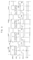
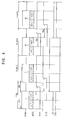
- FIGS. 2 , 3 and 4 are timing diagrams illustrating a method for displaying a stereoscopic image using the display apparatus of FIG. 1 .
- a left-eye image LI is outputted during an N-th frame F(N).
- 'N' is a positive integer.
- the left-eye image LI is outputted based on a vertical synchronization signal VSYNC.
- the N-th frame may include an active interval ACI and a blanking interval VBI.
- the left-eye image LI is outputted at the active interval ACI of the N-th frame, and may be maintained during the blanking interval VBI.
- the blanking interval VBI may be set to be less than approximately 10% of one conventional frame period. Alternatively, the blanking interval VBI may be set to be more than approximately 10% of one frame period. For example, the blanking interval VBI may be set to be greater than or equal to approximately 30% of one frame period.
- the left-eye image LI may be divided into a first left-eye image LI1 displayed on the first display block DB1 of the display panel 100 and a second left-eye image LI2 displayed on the second display block DB2 of the display panel 100.
- each of the first and second display blocks DB1 and DB2 may have a resolution of 1920 ⁇ 540.
- the left-eye image LI may have 1920 ⁇ 1080 image data
- each of the first and second left-eye images LI1 and LI2 may have 1920 ⁇ 540 image data.
- the display panel 100 may display a frame image having a resolution of 1920 ⁇ 1080 at a frame frequency of approximately 60 Hz or a multiple thereof.
- the light source driving part 500 drives the first light-emitting block 420a based on a first light-emitting control signal BLC1 and drives the second light-emitting block 420b based on a second light-emitting control signal BLC2.
- the first light-emitting control signal BLC1 and the second light-emitting control signal BLC2 may be transmitted by one wiring.
- each of the first and second light-emitting control signals BLC1 and BLC2 may be transmitted by different wirings.
- the first light-emitting block 420a may be turned on in response to the first light-emitting control signal BLC1 of a high level and may be turned off in response to the first light-emitting control signal BLC1 of a low level.
- the second light-emitting block 420b may be turned on in response to the second light-emitting control signal BLC2 of a high level and may be turned off in response to the second light-emitting control signal BLC2 of a low level.
- the first light-emitting block 420a may be turned on at a time that a first left-eye preset time TL1 is elapsed from a time in which the first left-eye image LI1 is outputted to the first display block DB1.
- the second light-emitting block 420b may be turned on at a time that a second left-eye preset time TL2 is elapsed from a time in which the second left-eye image LI2 is outputted to the second display block DB2.
- the first left-eye preset time TL1 or the second left-eye preset time TL2 may be set based on a response speed of a liquid crystal included in the display panel 100.
- the first left-eye preset time TL1 or the second left-eye preset time TL2 may be greater than or equal to a time required to achieve a luminance corresponding to approximately 60% of a luminance when the liquid crystal is saturated.
- the first left-eye preset time TL1 or the second left-eye preset time TL2 may be set based on a time in which one frame period is divided by the first and second light-emitting blocks 420a and 420b.
- the first left-eye preset time TL1 may be set to have a value greater than a time in which one frame period is divided by the first and second light-emitting blocks 420a and 420b.
- the shutter glasses 600 control opening/closing of the left-eye shutter 610 based on a first shutter control signal LSS, and control opening/closing the right-eye shutter 620 based on a second shutter control signal RSS.
- the shutter glasses 600 may open the left-eye shutter 610 in response to the first shutter control signal LSS of a high level, and may close the left-eye shutter 610 in response to the first shutter control signal LSS of a low level.
- An observer may view the first left-eye image displayed on the first display block DB1 through the left-eye shutter 610 while the first light-emitting block 420a is turned on, and may view the second left-eye image displayed on the second display block DB2 through the left-eye shutter 610 while the second light-emitting block 420b is turned on.
- a right image RI is outputted to the display panel 100.
- M is N+1 as an example is described in FIG. 2
- M is greater than N+1 as an example is described in FIGS. 3 and 4 .
- FIGS. 3 and 4 As shown in FIGS.
- a left-eye image LI may be outputted to the display panel 100 during the N-th frame F(N), and may be outputted to the display panel 100 during an interval from an (N+1)-th frame F(N+1) to an (M-1)-th frame F(M-1) that is a previous frame of an M-th frame that the right-eye image RI is outputted to the display panel 100.
- the left-eye image LI outputted from an (N+1)-th frame F(N+1) to an (M-1)-th frame F(M-1) is substantially identical to the left-eye image LI outputted from an N-th frame F(N).
- the left-eye image LI may be an image generated based on the left-eye image LI of the N-th frame F(N).
- the right-eye image RI outputted from an (M+1)-th frame F(M+1) to an (2M-N-1)-th frame F(2M-N-1) is substantially identical to the right-eye image RI of an M-th frame F(M).
- the right-eye image RI may be an image generated based on the right-eye image RI of the M-th frame F(M).
- the right-eye image RI may be an image corresponding to a black grayscale, which is outputted during an interval from an (M+1)-th frame F(M+1) to an (2M-N-1)-th frame F(2M-N-1).
- the right-eye image RI may be output in the active interval ACI of the M-th frame, and may be maintained during the blanking interval VBI.
- the right-eye image RI may be divided into a first right-eye image RI1 displayed on the first display block DB1 of the display panel 100 and a second right-eye image RI2 displayed on the second display block DB2 of the display panel 100.
- the first light-emitting block 420a may be turned on in response to the first light-emitting control signal BLC1 of a high level, and may be turned off in response to the first light-emitting control signal BLC1 of a low level.
- the first light-emitting block 420a is turned on at a time that a first right-eye preset time TR1 is elapsed from a time in which the first right-eye image RI1 is outputted to the first display block DB1.
- the second light-emitting block 420b may be turned on in response to the second light-emitting control signal BLC2 of a high level, and may be turned off in response to the second light-emitting control signal BLC2 of a low level.
- the second light-emitting block 420b is turned on at a time that a second right-eye preset time TR2 is elapsed from a time in which the second right-eye image RI2 is outputted to the second display block DB2.
- the first right-eye preset time TR1 or the second right-eye preset time TR2 may be set based on a response speed of a liquid crystal included in the display panel 100.
- the first right-eye preset time TR1 or the second right-eye preset time TR2 may be greater than or equal to a time required to achieve a luminance corresponding to approximately 60% of a luminance when the liquid crystal is saturated.
- the first left-eye preset time TL1 and the first right-eye preset time TR1 may be substantially equal to each other.
- the second left-eye preset time TL2 and the second right-eye preset time TR2 may be substantially equal to each other.
- the first and second left-eye preset times TL1 and TL2 and the first and second right-eye preset times TR1 and TR2 may be substantially equal to each other.
- the first right-eye preset time TR1 or the second right-eye preset time TR2 may be set to have a value greater than a time in which one frame period is divided by the first and second light-emitting blocks 420a and 420b.
- the shutter glasses 600 open the right-eye shutter 620 and close the left-eye shutter 610 while light generated from the first and second light-emitting blocks 420a and 420b are provided to the display panel 100 displaying the right-eye image RI.
- An emitting time of the first light-emitting block 420a is substantially smaller than or equal to a time that the first left-eye preset time TL1 or the first right-eye preset time TR1 is subtracted from one frame interval.
- An emitting time of the second light-emitting block 420b is substantially smaller than or equal to a time that the second left-eye preset time TL2 or the second right-eye preset time TR2 is subtracted from one frame interval.
- An observer may view the first right-eye image displayed on the first display block DB1 through the right-eye shutter 620 while the first light-emitting block 420a is turned on and may view the second right-eye image displayed on the second display block DB2 through the right-eye shutter 620 while the second light-emitting block 420b is turned on.
- the light source part 420 is divided into the first and second light-emitting blocks 420a and 420b so that each of the left-eye and right-eye images LI and RL is divided into two images.
- a light-emitting timing of the first and second light-emitting blocks 420a and 420b is controlled so that the left-eye image or the right-eye image is displayed on the display block of the display panel 100.
- the generation of crosstalk between the left-eye and right-eye images may be reduced or prevented.
- FIG. 5 is a plan view illustrating a light providing unit according to an exemplary embodiment of the present invention.
- the display apparatus may be substantially the same as the display apparatus discussed above with respect to FIG. 1 and may also include a light providing unit 401.
- a method of displaying a stereoscopic image according to an exemplary embodiment may be substantially the same as the method of displaying a stereoscopic image described above with respect to FIGS. 2 to 4 .
- a light providing unit 401 includes a first light-emitting block 432 and a second light-emitting block 434.
- Each of the first and second light-emitting blocks 432 and 434 includes a plurality of light sources 431.
- Each light source may be a light-emitting diode (LED).
- the first and second light-emitting blocks 432 and 434 are disposed below the display panel 100.
- the light providing unit 401 may further include a light-blocking member which is disposed between the first and second light-emitting blocks 432 and 434 and may prevent light from being leaked from the first light-emitting block 432 to the second light-emitting block 434 or from the second light-emitting block 434 to the first light-emitting block 432.
- the first and second light-emitting blocks 432 and 434 are disposed below the display panel 100 and light generated from the first and second light-emitting blocks 432 and 434 is directed onto the display panel 100.
- FIG. 6 is a plan view illustrating a light providing unit according to an exemplary embodiment of the present invention.
- the display apparatus may be substantially the same as the display apparatus described above with respect to FIG. 1 and may additionally include a light providing unit 402. Moreover, a method of displaying a stereoscopic image according to an exemplary embodiment may be substantially the same as the method of displaying a stereoscopic image described above with respect to FIGS. 2 to 4 .
- the light providing unit 402 includes a first light-emitting block 442 and a second light-emitting block 444.
- Each of the first and second light-emitting blocks 442 and 444 includes at least one light source 441.
- the light source 441 may be a fluorescent lamp.
- the first and second light-emitting blocks 442 and 444 are disposed below the display panel 100.
- the light providing unit 402 may further include a light-blocking member which is disposed between the first and second light-emitting blocks 442 and 444 and may prevent light from being leaked from the first light-emitting block 442 to the second light-emitting block 444 or from the second light-emitting block 444 to the first light-emitting block 442.
- the first and second light-emitting blocks 442 and 444 are disposed below the display panel 100 and light generated from the first and second light-emitting blocks 442 and 444 is directed onto the display panel 100.
- the display apparatus includes a display panel 100, a panel driving part 200, a timing control part 300, a light providing unit 403 and a light source driving part 500.
- the display apparatus may further include a pair of shutter glasses 600.
- the display panel 100 includes a plurality of pixels P which display an image.
- Each of the pixels includes a switching element TR electrically connected to a gate line GL and a data line DL, a liquid crystal capacitor CLC connected to the switching element TR and a storage capacitor CST connected to the switching element TR.
- the display panel 100 may include two substrates opposite to each other and a liquid crystal layer interposed between the two substrates.
- the panel driving part 200 may include a gate driving part 210 and a data driving part 230.
- the gate driving part 210 generates a gate signal for activating the gate line GL and may provide the gate line GL with the gate signal.
- the data driving part 230 converts an image signal received from the timing control part 300 into a data voltage.
- the data driving part 230 provides the data line DL with the data voltage.
- the timing control part 300 controls a driving timing of the display apparatus based on a synchronizing signal received from an external device (not shown). For example, the timing control part 300 receives a 3D image signal from an external device and provides the data driving part 230 with the 3D image signal. For example, the timing control part 300 generates a 3D image signal and provides the data driving part 230 with the 3D image signal.
- the 3D image signal may include a left-eye image and a right-eye image.
- the timing control part 300 controls a driving of the light source driving part 500 based on an image displayed on the display panel 100. Moreover, the timing control part 300 may control a driving of the shutter glasses 600 based on an image displayed on the display panel 100.
- the light providing unit 403 may include a light guide plate 410 and a light source part 450.
- the light guide plate 410 may be disposed at a first side surface of the light source part 420 to provide the display panel 100 with light provided from the light source part 450.
- the light source part 450 provides the display panel 100 with light.
- the light source part 450 may include k light-emitting blocks (wherein, 'k' is a positive integer greater than 3).
- the light source part 450 may include a first light-emitting block 450a, a second light-emitting block 450b, a third light-emitting block 450c and a fourth light-emitting block 450d, as shown in FIG. 6 .
- Each of the first to fourth light-emitting blocks 450a, 450b, 450c and 450d may include at least one light source (not shown).
- Each light source may be a light-emitting diode (LED).
- the light source may be a fluorescent lamp.
- the display panel 100 may be divided into a first display block DB1, a second display block DB2, a third display block DB3 and a fourth display block DB4 corresponding to the first to fourth light-emitting blocks 450a, 450b, 450c and 450d.
- the first light-emitting block 450a provides the first display block DB1 with light.
- the second light-emitting block 450b provides the second display block DB2 with light.
- the third light-emitting block 450c provides the third display block DB3 with light.
- the fourth light-emitting block 450d provides the fourth display block DB4 with light.
- the light providing unit 403 may further include light-blocking member (not shown).
- the light source part 450 may further include a fifth light-emitting block, a sixth light-emitting block, a seventh light-emitting block and an eighth light-emitting block that face the first to fourth light-emitting blocks 450a, 450b, 450c, and 450d, respectively.
- the light-emitting blocks facing each other may be driven in synchronous.
- an edge-type display apparatus in which the light source part 450 is disposed at a side surface of the light-guide plate 410 to direct light onto the display panel 100; however, the present invention is not limited to this particular configuration.
- a direct-type display apparatus may be adapted to exemplary embodiments of the present invention, in which the first to fourth light-emitting blocks 450a, 450b, 450c and 450d of the light source part 450 are disposed below the display panel 100 to directly provide light onto the display panel 100.
- the light source driving part 500 generates light-emitting control signals for driving the first to fourth light-emitting blocks 450a, 450b, 450c and 450d.
- the light source driving part 500 controls the first to fourth light-emitting blocks 450a, 450b, 450c and 450d at a time that first to fourth left-eye preset times or first to fourth right-eye preset times are elapsed from a time in which a left-eye image or a right-eye image is outputted to each of the display blocks, so that each of the display blocks is turned on.
- the light source driving part 500 controls the first light-emitting block 450a to emit light at a time that the first left-eye preset time is elapsed from a time in which corresponding left-eye image is outputted to the first display block DB1, and controls the second light-emitting block 450b to emit light at a time that the second left-eye preset time is elapsed from a time in which corresponding left-eye image is outputted to the second display block DB2.
- the light source driving part 500 controls the first light-emitting block 450a to emit light at a time that the first right-eye preset time is elapsed from a time in which corresponding right-eye image is outputted to the first display block DB1.
- the first to fourth left-eye preset times or the first to fourth right-eye preset times may be set based on a response speed of the liquid crystal included in the display panel 100.
- the first to fourth left-eye preset times or the first to fourth right-eye preset times may be greater than or equal to a time required to achieve a luminance corresponding to approximately 60% of a luminance when the liquid crystal is saturated.
- the first to fourth left-eye preset times or the first to fourth right-eye preset times may be set based on a time in which one frame period is divided by the number of first to fourth light-emitting blocks 450a, 450b, 450c and 450d.
- the first to fourth left-eye preset times or the first to fourth right-eye preset times may be set to have a value greater than a time in which one frame period is divided by the number of first to fourth light-emitting blocks 450a, 450b, 450c and 450d.
- the shutter glasses 600 include a left-eye shutter 610 and a right-eye shutter 620.
- the shutter glasses 600 may selectively open and close the left-eye shutter 610 and the right-eye shutter 620 in response to a shutter control signal received from the timing control part 300 and so on.
- the shutter glasses 600 open the left-eye shutter 610 and close the right-eye shutter 620, while light is provided to the first to fourth display blocks DB1, DB2, DB3 and DB4 displaying the left-eye image thereon.
- the shutter glasses 600 open the right-eye shutter 620 and close the left-eye shutter 610, while light is provided to the first to fourth display blocks DB1, DB2, DB3 and DB4 displaying the right-eye image thereon.
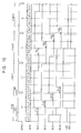
- FIGS. 8 , 9 and 10 are timing diagrams illustrating a method for displaying a stereoscopic image by the display apparatus of FIG. 7 .
- a left-eye image LI is outputted during an N-th frame F(N).
- 'N' is a positive integer.
- the left-eye image LI is outputted based on a vertical synchronization signal VSYNC.
- the N-th frame may include an active interval ACI and a blanking interval VBI.
- the left-eye image LI is outputted at the active interval ACI of the N-th frame and may be maintained during the blanking interval VBI.
- the blanking interval VBI may be set to be less than or equal to approximately 10% of one frame.
- the blanking interval VBI may be set to be approximately 5% to approximately 6% of one frame period.
- the left-eye image LI may be divided into a first left-eye image LI1, a second left-eye image LI2, a third left-eye image LI3 and a fourth left-eye image LI4 corresponding to the first to fourth display blocks DB1, DB2, DB3 and DB4.
- each of the first to fourth display blocks DB1, DB2, DB3 and DB4 may have a resolution of 1920 ⁇ 270.
- the left-eye image LI may have 1920 ⁇ 1080 image data
- each of the first to fourth left-eye images LI1, LI2, LI3 and LI4 may have 1920 ⁇ 270 image data.
- the display panel 100 may display a frame image having a resolution of 1920 ⁇ 1080 at a frame frequency of approximately 60 Hz or a multiple thereof.
- the light source driving part 500 generates a first light-emitting control signal BLC1, a second light-emitting control signal BLC2, a third light-emitting control signal BLC3 and a fourth light-emitting control signal BLC4 so as to respectively drive the first to fourth light-emitting blocks 450a, 450b, 450c and 450d.
- Each of the first to fourth light-emitting blocks 450a, 450b, 450c and 450d may be turned on in response to the light-emitting control signal of a high level, and may be turned off in response to the light-emitting control signal of a low level.
- the first light-emitting block 450a is turned on at a time that the first left-eye preset time TL1 is elapsed from a time in which the first left-eye image LI1 is outputted to the first display block DB 1.
- the second light-emitting block 450b is turned on at a time that the second left-eye preset time TL2 is elapsed from a time in which the second left-eye image LI2 is outputted to the second display block DB2.
- the third light-emitting block 450c is turned on at a time that the third left-eye preset time TL3 is elapsed from a time in which the third left-eye image LI3 is outputted to the third display block DB3.
- the fourth light-emitting block 450d is turned on at a time that the fourth left-eye preset time TL4 is elapsed from a time in which the fourth left-eye image LI4 is outputted to the fourth display block DB4.
- the first to fourth left-eye preset times TL1, TL2, TL3 and TL4 may be substantially equal to each other.
- the first to fourth left-eye preset times TL1, TL2, TL3 and TL4 may be greater than or equal to a time required to achieve a luminance corresponding to approximately 60% of a luminance when the liquid crystal is saturated.
- the shutter glasses 600 control opening/closing of the left-eye shutter 610 based on a first shutter control signal LSS and control opening/closing of the right-eye shutter 620 based on a second shutter control signal RSS.
- the shutter glasses 600 may open the left-eye shutter 610 in response to the first shutter control signal LSS of a high level and may close the left-eye shutter 610 in response to the first shutter control signal LSS of a low level.
- the shutter glasses 600 may open the right-eye shutter 620 in response to the second shutter control signal RSS of a high level and may close the right-eye shutter 620 in response to the second shutter control signal RSS of a low level.
- the shutter glasses 600 may open the left-eye shutter 610 and may close the right-eye shutter 620 while light generated from the first to fourth light-emitting blocks 450a, 450b, 450c and 450d is provided to the first to fourth display blocks DB1, DB2, DB3 and DB4 on which the left-eye image is displayed.
- an emitting time of the first to fourth light-emitting blocks 450a, 450b, 450c and 450d is substantially smaller than or equal to a time that each of the first to fourth left-eye preset times TL 1, TL2, TL3 and TL4 is subtracted from one frame interval.
- An observer may view the first left-eye image LI1 displayed on the first display block DB1 through the left-eye shutter 610 while the first light-emitting block 420a is turned on and may view the second left-eye image LI2 displayed on the second display block DB2 through the left-eye shutter 610 while the second light-emitting block 420b is turned on.
- An observer may view the third left-eye image LI3 displayed on the third display block DB3 through the left-eye shutter 610 while the third light-emitting block 450c is turned on and may view the fourth left-eye image LI4 displayed on the fourth display block DB4 through the left-eye shutter 610 while the fourth light-emitting block 450d is turned on.
- a right-eye image RI is outputted to the display panel 100.
- FIG. 8 shows that M is N+1
- FIGS. 9 and 10 show that M is greater than N+1.
- a left-eye image LI may be outputted to the display panel 100 during the N-th frame F(N) and the left-eye image LI may be outputted to the display panel 100 during an interval from an (N+1)-th frame F(N+1) to an (M-1)-th frame F(M-1) that is a previous frame of an M-th frame in which the right-eye image RI is outputted to the display panel 100.
- the left-eye image LI outputted during an interval from the (N+1)-th frame F(N+1) to the (M-1)-th frame F(M-1) may be substantially equal to a left-eye image LI of an N-th frame or an image generated based on a left-eye image LI of the N-th frame.
- the left-eye image LI outputted during the interval from the (N+1)-th frame F(N+1) to the (M-1)-th frame F(M-1) may substantially be a black image represented in grayscale.
- the right-eye image RI may be outputted during the active interval ACI of the M-th frame, and may be held during the blanking interval VBI.
- the right-eye image RI may be divided into a first right-eye image RI1, a second right-eye image RI2, a third right-eye image RI3 and a fourth right-eye image RI4 corresponding to the first to fourth display blocks DB1, DB2, DB3 and DB4 of the display panel 100, respectively.
- Each of the first to fourth light-emitting blocks 450a, 450b, 450c and 450d may be turned on in response to a light-emitting control signal of a high level and may be turned off in response to a light-emitting control signal of a low level.
- the first light-emitting block 450a is turned on at a time that a first right-eye preset time TR1 is elapsed from a time in which the first right-eye image RI1 is outputted to the first display block DB 1.
- the second light-emitting block 450b is turned on at a time that a second right-eye preset time TR2 is elapsed from a time in which the second right-eye image RI2 is outputted to the second display block DB2.
- the third light-emitting block 450c is turned on at a time that a third right-eye preset time TR3 is elapsed from a time in which the third right-eye image RI3 is outputted to the third display block DB3.
- the fourth light-emitting block 450d is turned on at a time that a fourth right-eye preset time TR4 is elapsed from a time in which the fourth right-eye image RI4 is outputted to the fourth display block DB4.
- the first to fourth right-eye preset times TR1, TR2, TR3 and TR4 may be substantially equal to each other. Moreover, the first to fourth right-eye preset times TR1, TR2, TR3 and TR4 may be greater than or equal to a time required to achieve a luminance corresponding to approximately 60% of a luminance when the liquid crystal is saturated. Moreover, the first left-eye preset time TL1 and the first right-eye preset time TR1 may be substantially equal to each other and the second left-eye preset time TL2 and the second right-eye preset time TR2 may be substantially equal to each other.
- the third left-eye preset time TL3 and the third right-eye preset time TR3 may be substantially equal to each other and the fourth left-eye preset time TL4 and the fourth right-eye preset time TR4 may be substantially equal to each other.
- the first to fourth left-eye preset times TL1, TL2, TL3 and TL4 and the first to fourth right-eye preset times TR1, TR2, TR3 and TR4 may be substantially equal to each other.
- the shutter glasses 600 open the right-eye shutter 620 and close the left-eye shutter 610, while light emitted from the first to fourth light-emitting blocks 450a, 450b, 450c and 450d are respectively provided to the first to fourth display blocks DB 1, DB2, DB3 and DB4 on which the right-eye image is displayed.
- an emitting time of the first to fourth light-emitting blocks 450a, 450b, 450c and 450d is substantially smaller than or equal to a time that each of the first to fourth right-eye preset times TR1, TR2, TR3 and TR4 is subtracted from one frame interval.
- An observer may view the first right-eye image RI1 displayed on the first display block DB1 through the right-eye shutter 620 while the first light-emitting block 450a is turned on and may view the second right-eye image RI2 displayed on the second display block DB2 through the right-eye shutter 620 while the second light-emitting block 450b is turned on.
- An observer may view the third right-eye image RI3 displayed on the third display block DB3 through the right-eye shutter 620 while the third light-emitting block 450c is turned on and may view the fourth right-eye image RI4 displayed on the fourth display block DB4 through the right-eye shutter 620 while the fourth light-emitting block 450d is turned on.
- FIGS. 7 to 10 illustrate four display blocks and four light-emitting blocks as an example.
- the number of the display blocks and the number of light-emitting blocks may be three or greater than or equal to five.
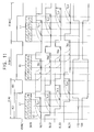
- FIG. 11 is a timing diagram illustrating a method for displaying a stereoscopic image in accordance with an exemplary embodiment of the present invention.
- the display apparatus may be substantially the same as the display apparatus of FIGS. 7 to 10 with the addition of a vertical synchronization signal VSYNC applied to the timing control part 300, so that a description of the display apparatus may refer back to FIG. 6 .
- a method of displaying a stereoscopic image according to an exemplary embodiment may be substantially the same as the method of displaying a stereoscopic image described above with reference to FIGS. 8 to 10 with the addition of the synchronization signal VSYNC, first, second, third and fourth light-emitting control signals BLC1, BLC2, BLC3 and BLC4, and first and second shutter control signals LSS and RSS.
- a left-eye image LI is outputted to the display panel 100.
- the left-eye image LI is outputted in synchronized with a vertical synchronization signal VSYNC.
- the left-eye image LI is outputted at the active interval ACI of the vertical synchronization signal VSYNC and is maintained during the blanking interval VBI.
- the blanking interval VBI may be set to be greater than or equal to approximately 10% of one frame period. In this case, the blanking interval VBI may be set to be greater than or equal to approximately 30% of one frame period. For example, the blanking interval VBI may be set to be greater than or equal to approximately 32% of one frame period.
- the display panel 100 may be divided into the first to fourth display blocks DB 1, DB2, DB3 and DB4 corresponding to the first to fourth light-emitting blocks 450a, 450b, 450c and 450d, respectively.
- the left-eye image LI may be divided into a first left-eye image LI1, a second left-eye image LI2, a third left-eye image LI3 and a fourth left-eye image LI4 corresponding to the first to fourth display blocks DB1, DB2, DB3 and DB4, respectively.
- the third light-emitting block 450c is turned on at a time that the third left-eye preset time TL3 is elapsed from a time in which the third left-eye image LI3 is outputted to the third display block DB3.
- the fourth light-emitting block 450d is turned on at a time that the fourth left-eye preset time TL4 is elapsed from a time in which the fourth left-eye image LI4 is outputted to the fourth display block DB4.
- the first to fourth left-eye preset times TL1, TL2, TL3 and TL4 may be set based on a response speed of the liquid crystal. For example, the first to fourth left-eye preset times TL1, TL2, TL3 and TL4 may be greater than or equal to a time required to achieve a luminance corresponding to approximately 60% of a luminance when the liquid crystal is saturated.
- a right image RI is outputted to the display panel 100.
- M is N+1 as an example is described above with reference to FIG. 11 .
- the right-eye image RI may be divided into a first right-eye image RI1, a second right-eye image RI2, a third right-eye image RI3 and a fourth right-eye image RI4 corresponding to the first to fourth display blocks DB1, DB2, DB3 and DB4 of the display panel 100, respectively.
- Each of the first to fourth light-emitting blocks 450a, 450b, 450c and 450d may be turned on in response to a light-emitting control signal of a high level and may be turned off in response to a light-emitting control signal of a low level.
- the first light-emitting block 450a is turned on at a time that a first right-eye preset time TR1 is elapsed from a time in which the first right-eye image RI1 is outputted to the first display block DB 1.
- the second light-emitting block 450b is turned on at a time that a second right-eye preset time TR2 is elapsed from a time in which the second right-eye image RI2 is outputted to the second display block DB2.
- the third light-emitting block 450c is turned on at a time that a third right-eye preset time TR3 is elapsed from a time in which the third right-eye image RI3 is outputted to the third display block DB3.
- the fourth light-emitting block 450d is turned on at a time that a fourth right-eye preset time TR4 is elapsed from a time in which the fourth right-eye image RI4 is outputted to the fourth display block DB4.
- the first to fourth right-eye preset times TR1, TR2, TR3 and TR4 may be greater than or equal to a time required to achieve a luminance corresponding to approximately 60% of a luminance when the liquid crystal is saturated.
- the first left-eye preset time TL1 and the first right-eye preset time TR1 may be substantially equal to each other, and the second left-eye preset time TL2 and the second right-eye preset time TR2 may be substantially equal to each other.
- the third left-eye preset time TL3 and the third right-eye preset time TR3 may be substantially equal to each other, and the fourth left-eye preset time TL4 and the fourth right-eye preset time TR4 may be substantially equal to each other.
- the first to fourth left-eye preset times TL1, TL2, TL3 and TL4 and the first to fourth right-eye preset times TR1, TR2, TR3 and TR4 may be substantially equal to each other.
- the shutter glasses 600 open the right-eye shutter 620 and close the right-eye shutter 620, while light emitted from the first to fourth light-emitting blocks 450a, 450b, 450c and 450d are provided to the first to fourth display blocks DB1, DB2, DB3 and DB4 on which the left-eye image is displayed.
- the left-eye shutter 610 is opened at a time in which the first light-emitting block 450a is turned on corresponding to the right-eye image RI and is closed before the first light-emitting block 450a is turned on in correspondence with the right-eye image RI.
- An observer may view the first left-eye image LI1 through the left-eye shutter 610 while the first light-emitting block 450a is turned on and may view the second left-eye image LI2 through the left-eye shutter 610 while the second light-emitting block 420b is turned on.
- An observer may view the third left-eye image LI3 through the left-eye shutter 610 while the third light-emitting block 450c is turned on and may view the fourth left-eye image LI4 through the left-eye shutter 610 while the fourth light-emitting block 450d is turned on.
- an active interval for displaying the left-eye image LI or the right-eye image RI may be shortened.
- a driving margin of the light source part 450 may be determined.
- a light-emitting duty width of the first to fourth light-emitting blocks 450a, 450b, 450c and 450d may be increased with respect to a method of displaying a stereoscopic image in accordance with the description provided above with respect to FIG. 8 .
- luminance of the display panel 100 may be increased. Accordingly, a display quality of a 3D stereoscopic image may be increased.
- FIG. 11 four display blocks and four light-emitting blocks are shown.
- the number of the display blocks and the number of light-emitting blocks may be three or greater or equal to five.
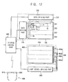
- FIG. 12 is a block diagram illustrating a display apparatus according to an exemplary embodiment of the present invention.
- the display apparatus includes a display panel 100, a panel driving part 200, a timing control part 300, a light providing unit 400 and a light source driving part 500.
- the display apparatus may further include a pair of shutter glasses 600.
- the same reference numerals will be used to refer to the same or like parts as those described above with reference to FIG. 7 , and any further explanation concerning the above elements will be omitted.
- the light guide plate 410 is disposed below the display panel 100.
- the light source part 450 includes first to k-th light-emitting blocks (wherein, 'k' is a positive integer) that are arranged in a scanning direction.
- the light source part 450 includes first, second, third and fourth light-emitting blocks 450a, 450b, 450c and 450d.
- Each of the first to fourth light-emitting blocks 450a, 450b, 450c and 450d includes a light source generating light.
- the first to fourth light-emitting blocks 450a, 450b, 450c and 450d may be disposed at a first edge of the light guide plate 410 as shown in FIG. 12 .
- the light source driving part 500 controls a turning on and a turning off of the first to fourth light-emitting blocks 450a, 450b, 450c and 450d of the light source part 450 in accordance with an image displayed on the display panel 100.
- the first to fourth light-emitting blocks 450a, 450b, 450c and 450d are sequentially driven.
- the light source driving part 500 individually controls light-emitting intervals of the first to fourth light-emitting blocks 450a, 450b, 450c and 450d.
- an all off interval in which each of the first to fourth light-emitting blocks 450a, 450b, 450c and 450d are turned off and a sequential on interval in which each of the first to fourth light-emitting blocks 450a, 450b, 450c and 450d are sequentially turned on are included in one frame period.
- the shutter glasses 600 may include a left-eye shutter 610 and a right-eye shutter 620.
- the left-eye shutter 610 and the right-eye shutter 620 may each include a liquid crystal shutter in which an electric field is used to align liquid crystal to either permit or block light.
- the shutter glasses 600 may selectively open and close the left-eye shutter 610 and the right-eye shutter 620 based on a shutter control signal provided from the timing control part 300.
- the timing control part 300 may provide the shutter control signal to the shutter glasses either wirelessly or through a cable running therebetween.
- the timing control part 300 sequentially provides the left-eye opening signal and the right-eye closing signal to the shutter glasses 600 within the all off interval of the N-th frame.
- the timing control part 300 sequentially provides the right-eye opening signal and the left-eye closing signal to the shutter glasses 600 within the all off interval of the (N+1)-th frame.
- the shutter glasses 600 may generate a left-eye shutter signal for opening and closing the left-eye shutter 610 and a right-eye shutter signal for opening and closing the right-eye shutter 620 based on the left-eye opening signal, the right-eye closing signal, the right-eye opening signal and the left-eye closing signal from the timing control part 300 to drive the left-eye shutter 610 and the right-eye shutter 620.
- the shutter glasses 600 starts the opening and closing operation within the all off interval, so that a crosstalk (i.e., a 3D crosstalk) between a left-eye image and a right-eye image may be reduced or prevented.
- the 3D crosstalk may otherwise be attributable to the right eye seeing the left-eye image or the left eye seeing the right-eye image in the period of time between when the corresponding shutter begins to close and when it is fully closed owing to the response speed of the liquid crystal of the shutter glasses 600.
- the all off interval may be greater than or equal to a response speed of a liquid crystal of the shutter glasses 600.
- the left-eye data frame may be a white data and the right-eye data frame may be a black data.
- FIG. 13 includes timing diagrams illustrating a first example of a method for displaying a stereoscopic image by the display apparatus of FIG. 12 .
- the panel driving part 200 outputs a left-eye data frame to the display panel 100.
- the left-eye data frame may include first, second, third and fourth left-eye data blocks LI1, LI2, LI3 and LI4.
- the data frame may be data corresponding to 920 ⁇ 1080 resolution and each of the data blocks may be data corresponding to 920 ⁇ 270 resolution.
- the panel driving part 200 sequentially outputs the first left-eye data block LI1 in a horizontal line unit during a first interval I11 of the N-th frame F(N) and outputs the second left-eye data block LI2 in a horizontal line unit during a second interval I12 of the N-th frame F(N).
- the panel driving part 200 sequentially outputs the third left-eye data block LI3 in a horizontal line unit during a third interval I13 of the N-th frame F(N) and outputs the fourth data block LI4 for the left-eye in a horizontal line unit during a fourth interval I14 of the N-th frame F(N).
- the panel driving part 200 outputs the left-eye data frame to the display panel 100 during the N-the frame F(N) and the display panel 100 displays a left-eye image delayed by a response speed of a liquid crystal with respect to a starting point of the N-th frame F(N).
- the panel driving part 200 outputs a right-eye data frame to the display panel 100.
- the right-eye data frame includes first, second, third and fourth right-eye data blocks RI1, RI2, RI3 and RI4.
- the panel driving part 200 sequentially outputs the first right-eye data block RI1 in a horizontal line unit during a first interval I21 of an (N+1)-th frame F(N+1).
- the second right-eye data block RI2 is sequentially output in a horizontal line unit during a second interval I22 of the (N+1)-th frame F(N+1).
- the panel driving part 200 sequentially outputs the third right-eye data block RI3 in a horizontal line unit during a third interval I23 of the (N+1)-th frame F(N+1).
- the fourth right-eye data block RI4 is sequentially output in a horizontal line unit during a third interval I24 of the (N+1)-th frame F(N+1).
- the panel driving part 200 outputs the right-eye data frame to the display panel 100 during the (N+1)-th frame F(N+1) and the display panel 100 displays a right-eye image delayed by a response speed of a liquid crystal LC_RS with respect to a starting point of the (N+1)-th frame F(N+1).
- the light source driving part 500 generates first, second, third and fourth light-emitting control signals BLC 1, BLC2, BLC3 and BLC4 and drives the light source part 450, and in particular, the first to fourth light-emitting blocks 450a, 450b, 450c and 450d, respectively.
- a light-emitting interval having a high level which turns on each light-emitting blocks and a light-outing having a low level which turns off each light-emitting blocks may be repeated in a frame period T.
- the first light-emitting block 450a is turned on or turned off in response to the first light-emitting control signal BLC1.
- the first light-emitting control signal BLC1 has a first light-emitting interval OP11.
- the first light-emitting interval OP11 is started at a time after the set time Rt is elapsed from a start point of an N-th frame F(N).
- the time between the start of the first light-emitting interval OP11 and the time after the set time Rt has elapsed after the start point of the N-th frame F(N) may also be influenced by a response speed of a liquid crystal of the display panel 100.
- the first light-emitting block 450a emits light during the first light-emitting interval OP1 in response to the first light-emitting control signal BLC1. As shown in FIG. 13 , the first light-emitting block 450a emits light during the first light-emitting interval OP11 from a time in which an outputting of the last line data of the third left-eye data block LI3 is completed, in response to the first light-emitting control signal BLC 1.
- the first light-emitting block OP11 may be approximately 1/5 of the frame period T.
- a first left-eye block image corresponding to the first left-eye data block LI1 is completed on the first display block DB1
- second, third and fourth left-eye block images are not completed on the second, third and fourth display blocks DB2, DB3 and DB4, due to a response speed of a liquid crystal LC_RS.
- the first light-emitting block 450a emits light during an interval in which the first left-eye block image is completed and within which the first display block DB1 is maintained.
- the first right-eye data block RI1 is provided to the first display block DB1
- the first right-eye block image and the first right-eye block image are mixed to be displayed on the first display block DB 1.
- third and fourth left-eye block images are not completed on the third and fourth display blocks DB3 and DB4 due to a response speed of a liquid crystal.
- the second light-emitting block 450b emits light during an interval in which the second left-eye block image is completed and within which the second display block DB2 is maintained.
- a first right-eye block image is displayed on the first display block DB1, and a mixing image in which a second left-eye block image and a second right-eye block image are mixed is displayed on the second display block DB2.
- a fourth left-eye block image is not completed on the fourth display block DB4.
- the third light-emitting block 450c emits light during an interval in which the third left-eye block image is completed and within which the third display block DB3 is maintained.
- the fourth light-emitting block 450d is simultaneously turned on after the third light-emitting interval OP 13 in response to the fourth light-emitting control signal BLC4.
- the fourth light-emitting block 450d emits light during the fourth light-emitting interval OP14.
- the fourth light-emitting interval OP14 may correspond to approximately 1/5 of the frame period T.
- a fourth left-eye block image corresponding to the fourth left-eye data block LI4 is completed on the fourth display block DB4.
- a first right-eye block image is displayed on the first display block DB1 and a second left-eye block image and a second right-eye block image are mixed and displayed on the second display block DB2.
- a third left-eye block image and a third right-eye block image are mixed and displayed on the third display block DB3.
- the fourth light-emitting block 450d emits light during an interval in which the fourth left-eye block image is completed and within which the fourth display block DB4 is maintained.
- the light source part 450 has a delay difference Dt for a start point of the N-th frame F(N) and repeats an operation in the frame period T.
- An operation period of the light source part 450 has a sequential on interval SQ_ON1 corresponding to approximately 4T/5 interval within which the first to fourth light-emitting blocks 450a, 450b, 450c and 450d sequentially emit light.
- the operation period of the light source part also has an all off interval ALL_OFF1 in which the first to fourth light-emitting blocks 450a, 450b, 450c and 450d are turned off for approximately a T/5 interval before the first light-emitting block 450a emits light.
- the shutter glasses 600 generate a left-eye shutter signal LSS and a right-eye shutter signal RSS and drive the left-eye shutter 610 and the right-eye shutter 620.
- the left-eye shutter 610 may be opened when the left-eye shutter signal LSS has a high level and may be closed when the left-eye shutter signal LSS has a low level.
- the right-eye shutter 620 may be opened when the right-eye shutter signal RSS has a high level and may be closed when the right-eye shutter signal RSS has a low level.
- the display panel 100 displays the left-eye image during a period of time from the first light-emitting interval OP 11 to the fourth light-emitting interval OP 14.
- the left-eye shutter signal LSS has an opening interval OPP corresponding to the first to fourth light-emitting intervals OP11, OP12, OP13 and OP14.
- the left-eye shutter 610 is opened during the opening interval OPP.
- the right-eye shutter signal RSS has a close interval CLP corresponding to the first to fourth light-emitting intervals OP11, OP12, OP13 and OP14.
- the right-eye shutter 620 is closed during the opening interval OPP.
- Each of the opening interval OPP and the close interval CLP includes an all off interval ALL_OFF1 within which the first, second, third and fourth light-emitting blocks 450a, 450b, 450c and 450d are turned off.
- a falling time is greater than a rising time in accordance with the response speed of a liquid crystal of the shutter glasses 600. Accordingly, a rising time point of the left-eye signal LSS leads a falling time point of the right-eye shutter signal RSS and a driving delay time of the shutter glasses 600 may be decreased. As such, the opening intervals OPP of the left-eye and right-eye shutter signals LSS and RDD may be greater than the closing interval CLP.
- crosstalk between the left-eye image and the right-eye image due to a response speed of a liquid crystal SLC_RS of the shutter glasses 600 may be reduced or prevented.
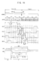
- FIG. 14 includes timing diagrams illustrating a second example of a method for displaying a stereoscopic image by the display apparatus of FIG. 12 .
- the panel driving part 200 outputs left-eye data frames LI1, LI2, LI3 and LI4 to the display panel 100 during an N-th frame F(N), and outputs right-eye data frames RI1, RI2, RI3 and RI4 during an (N+1)-th frame F(N+1), as shown in FIG. 13 .
- the light source driving part 500 sequentially drives the first to fourth light-emitting blocks 450a, 450b, 450c and 450d after a set time Rt.
- the set time Rt follows a starting point of one frame and takes into consideration a driving margin time of the display panel 100 which is influenced by a response speed of a liquid crystal.
- the first light-emitting block 450a is turned on or turned off in response to the first light-emitting control signal BLC1.
- the first light-emitting control signal BLC1 has a first light-emitting interval OP11.
- the first light-emitting interval OP11 is started after the set time Rt has elapsed. This point is a start point of an N-th frame F(N) and is influenced by a response speed of a liquid crystal of the display panel 100.
- the first light-emitting block 450a emits light during the light-emitting interval OP11 from a time in which an outputting of the last line data of the third left-eye data block LI3 is completed, in response to the first light-emitting control signal BLC1.
- the first light-emitting block OP11 may be approximately 1/5 of the frame period T.
- the first light-emitting block 450a emits light during an interval in which the first left-eye block image is completed on and within which the first display block DB1 is maintained.
- the second light-emitting block 450b is turned on or turned off in response to the second light-emitting control signal BLC2.
- the second light-emitting control signal BLC2 has a second light-emitting interval OP 12.
- the second light-emitting interval OP 12 has a first overlap interval OV1 which at least partially overlaps the first light-emitting interval OP11.
- the fourth overlap interval OV1 may be approximately 1/4 of the first light-remitting interval OP11.
- the second light-emitting block 450b is turned on during the first light-emitting interval OP11 and during the first overlap interval OV1 in response to the second light-emitting control signal BLC2. Light is thereby emitted during the second light-emitting interval OP 12.
- the second light-emitting interval OP12 may be approximately 1/5 of the frame period T.
- a second left-eye block image corresponding to the second left-eye data block LI2 is completed on the second display block DB2.
- the second light-emitting block 450b emits light during an interval in which the second left-eye block image is completed at and within which the second display block DB2 is maintained.
- the first overlap interval OV11 may be set in various manners. For example, in accordance with the response speed of a liquid crystal, the first overlap interval OV11 may be set within a period from a time that the second left-eye block image is completed on the second display block DB2 of the first light-emitting interval OP11 to a time that the first light-emitting interval OP11 is ended.
- the first overlap interval OV11 may be approximately 1/20 of the frame period T.
- the third light-emitting block 450c is turned on or turned off in response to the third light-emitting control signal BLC3.
- the third light-emitting control signal BLC3 has a third light-emitting interval OP 13.
- the third light-emitting interval OP 13 has a second overlap interval OV12 which is at least partially overlapping the second light-emitting interval OP12.
- the second overlap interval OV12 may be approximately 1/20 of the frame period T.
- the third light-emitting block 450c is turned on during the second light-emitting interval OP12 corresponding to the second overlap interval OV12 in response to the third light-emitting control signal BLC3.
- the third light-emitting block 450c emits light during the third light-emitting interval OP13.
- the third light-emitting interval OP13 may be approximately 1/5 of the frame period T.
- a third left-eye block image corresponding to the third left-eye data block LI3 is completed on the third display block DB3.
- the third light-emitting block 450c emits light during an interval in which the third left-eye block image is completed and within which the third display block DB3 is maintained.
- the second overlap interval OV12 may be set in various manners. For example, in accordance with the response speed of a liquid crystal, the second overlap interval OV12 may be set within a period of time from the time the third left-eye block image is completed on the third display block DB3 of the second light-emitting interval OP 12 to a time that the second light-emitting interval OP11 is ended.
- the fourth light-emitting block 450d is turned on or turned off in response to the fourth light-emitting control signal BLC4.
- the fourth light-emitting control signal BLC4 has a fourth light-emitting interval OP 14.
- the fourth light-emitting interval OP 14 has a third overlap interval OV13 which at least partially overlaps the third light-emitting interval OP13.
- the third overlap interval OV13 may be approximately 1/20 of the frame period T.
- the fourth light-emitting block 450d is turned on during the third light-emitting interval OP13 corresponding to the third overlap interval OV13 in response to the fourth light-emitting control signal BLC4.
- the fourth light-emitting block 450d emits light during the fourth light-emitting interval OP14.
- the fourth light-emitting interval OP 14 may be approximately 1/5 of the frame period T.
- a fourth left-eye block image corresponding to the fourth left-eye data block LI4 is completed on the fourth display block DB4.
- the fourth light-emitting block 450d emits light during an interval in which the fourth left-eye block image is completed at and within which the fourth display block DB4 is maintained.
- the third overlap interval OV13 may be set in various manners. For example, in accordance with the response speed of a liquid crystal, the third overlap interval OV13 may be set within a period of time from a time that the fourth left-eye block image is completed on the fourth display block DB4 of the third light-emitting interval OP31 to a time that the third light-emitting interval OP13 is ended. Moreover, the first, second and third overlap intervals OV11, OV12 and OV13 may be set in different manners.
- the light source part 450 has a delay difference Dt for a start point of the N-th frame F(N) and repeats an operation in the frame period T.
- An operation period of the light source part 450 has a sequential on interval SQ_ON2 corresponding to approximately 3T/5 interval within which the first to fourth light-emitting blocks 450a, 450b, 450c and 450d sequentially emit light.
- the operation period of the light source part 450 also has an all off interval ALL_OFF2 within which the first to fourth light-emitting blocks 450a, 450b, 450c and 450d are turned off for approximately 2T/5 interval before the first light-emitting block 450a emits light due to the first, second and third overlap intervals OV11, OV12 and OV13.
- Opening and closing operations of the left-eye shutter 610 and the right-eye shutter 620 are activated within the all off interval ALL_OFF2.
- a liquid crystal margin time may be determined according to a response speed of a liquid crystal SLC_RS of the left-eye shutter 610 and the right-eye shutter 620.
- the all off interval ALL_OFF2 may be greater than the response speed of a liquid crystal SLC_RS of the shutter glasses 600.
- the all off interval ALL_OFF2 may determine the liquid crystal driving time of the shutter glasses 600.
- crosstalk between the left-eye image and the right-eye image due to a response speed of a liquid crystal SLC_RS of the shutter glasses 600 may be reduced or eliminated.
- FIG. 15 includes timing diagrams illustrating a method for displaying a stereoscopic image using the display apparatus of FIG. 12 according to an exemplary embodiment of the present invention.
- the panel driving part 200 outputs left-eye data frames LI1, LI2, LI3 and LI4 to the display panel 100 during an N-th frame F(N), and outputs right-eye data frames RI1, RI2, RI3 and RI4 during an (N+1)-th frame F(N+1), as shown in FIG. 13 .
- the light source driving part 500 sequentially drives the first to fourth light-emitting blocks 450a, 450b, 450c and 450d after a set time Rt is elapsed with respect to a starting point of one frame.
- a driving margin time of the display panel 100 that is influenced by a response speed of a liquid crystal LC_RS may also be used to determine the timing of the light source driving part 500.
- the second light-emitting block 450b is turned on or turned off in response to the second light-emitting control signal BLC2.
- the second light-emitting control signal BLC2 has a second light-emitting interval OP22.
- the second light-emitting interval OP22 has a first overlap interval OV21 which at least partially overlaps the first light-emitting interval OP1.
- the first overlap interval OV11 may be approximately 1/20 of the frame period T.
- the first overlap interval OV21 may be set in various manners.
- the third light-emitting control signal BLC3 has a third light-emitting interval OP23.
- the third light-emitting interval OP23 has a second overlap interval OV12 at least partially overlapping the second light-emitting interval OP22.
- the second overlap interval OV12 may be approximately 1/20 of the frame period T.
- the second overlap interval OV12 may be set in various manners. For example, in accordance with the response speed of a liquid crystal, the second overlap interval OV12 may be set within a period of time from the time that the third left-eye block image is completed on the third display block DB3 of the second light-emitting interval OP22 to a time that the second light-emitting interval OP22 is ended.
- the fourth light-emitting control signal BLC4 has a fourth light-emitting interval OP24.
- the fourth light-emitting interval OP24 has a third overlap interval OV13 at least partially overlapping the third light-emitting interval OP23.
- the third overlap interval OV13 may be approximately 1/20 of the frame period T.
- the third overlap interval OV13 may be set in various manners. For example, in accordance with the response speed of a liquid crystal, the third overlap interval OV23 may be set within a period of time from the time that the fourth left-eye block image is completed on the fourth display block DB4 of the third light-emitting interval OP23 to a time that the third light-emitting interval OP23 is ended.
- the first, second and third overlap intervals OV11, OV12 and OV13 may be set in different manners.
- the operation period of the light source part 450 also has an all off interval ALL_OFF3 within which the first to fourth light-emitting blocks 450a, 450b, 450c and 450d are turned off for approximately 3T/20 interval before the first light-emitting block 450a emits light due to the first, second and third overlap intervals OV21, OV22 and OV23.
- the light-emitting interval may be greater than that described above with reference FIGS. 13 and 14 , and luminance characteristics may be increased.
- the light source driving part 500 generates first, second, third and fourth light-emitting control signals BLC1, BLC2, BLC3 and BLC4 and drives the light source part 450including the first to fourth light-emitting blocks 450a, 450b, 450c and 450d, respectively.
- the first light-emitting block 450a is turned on or turned off in response to the first light-emitting control signal BLC1.
- the first light-emitting control signal BLC1 has a first light-emitting interval OP11.
- the first light-emitting interval OP11 is started from an interval in which the set time Rt has elapsed from a start point of an N-th frame F(N) in accordance with a response speed of a liquid crystal of the display panel 100.
- the set time Rt may be approximately 3/4 of the frame period T.
- the first light-emitting interval OP11 may be approximately 1/5 of the frame period T.
- the first light-emitting block 450a emits light during the first light-emitting interval OP11 from a time in which an outputting of the last line data of the third left-eye data block LI3 is completed, in response to the first light-emitting control signal BLC1.
- a first left-eye block image corresponding to the first left-eye data block LI1 is completed on the first display block DB1.
- the first light-emitting block 450a emits light during an interval in which the first left-eye block image is completed and within which the first display block DB1 is maintained.
- the second light-emitting block 450b is turned on or turned off in response to the second light-emitting control signal BLC2.
- the second light-emitting control signal BLC2 has a second light-emitting interval OP 12.
- the second light-emitting interval OP 12 has a first overlap interval OV11 at least partially overlapping the first light-emitting interval OP11.
- the first overlap interval OV11 may be approximately 1/20 of the frame period T.
- the second light-emitting block 450b is turned on during the first light-emitting interval OP11 corresponding to the first overlap interval OV1 in response to the second light-emitting control signal BLC2.
- the second light-emitting block 450b emits light during the second light-emitting interval OP12.
- the first overlap interval OV11 may be set in various manners. For example, in accordance with the response speed of a liquid crystal, the first overlap interval OV 11 may be set within a period of time from a time that the second left-eye block image is completed on the second display block DB2 of the first light-emitting interval OP11 to a time that the first light-emitting interval OP11 is ended.
- the third light-emitting interval OP 13 may be approximately 1/5 of the frame period T.
- a third left-eye block image corresponding to the third left-eye data block LI3 is completed on the third display block DB3.
- the third light-emitting block 450c emits light during an interval in which the third left-eye block image is completed and within which the third display block DB3 is maintained.
- the fourth light-emitting block 450d is turned on or turned off in response to the fourth light-emitting control signal BLC4.
- the fourth light-emitting control signal BLC4 has a fourth light-emitting interval OP 14.
- the fourth light-emitting interval OP 14 has a third overlap interval OV13 which at least partially overlaps the third light-emitting interval OP13.
- the second overlap interval OV12 may be approximately 1/20 of the frame period T.
- the fourth light-emitting block 450d is turned on during the third light-emitting interval OP 13 corresponding to the second overlap interval OV12 in response to the fourth light-emitting control signal BLC4.
- the fourth light emitting block 450d emits light during the fourth light-emitting interval OP14.
- the fourth light-emitting interval OP 14 may be approximately 1/5 of the frame period T.
- a fourth left-eye block image corresponding to the fourth left-eye data block LI4 is completed on the fourth display block DB4.
- the fourth light-emitting block 450d emits light during an interval in which the fourth left-eye block image is completed and within which the fourth display block DB4 is maintained.
- the interval A1 may be set in various manners and may depend upon an interval in which the third left-eye block image is maintained within on the third display block DB3 in accordance with the response speed of a liquid crystal and the first and second overlap intervals OV11 and OV12.
- the first overlap interval OV11 may be different from the second overlap interval OV12.
- the light source part 450 has a delay difference Dt for a start point of the N-th frame F(N) and repeats an operation in the frame period T.
- An operation period of the light source part 450 has a sequential on interval SQ_ON4 and an all off interval ALL_OFF.
- the second light-emitting block 450b at least partially overlaps the first light-emitting block 450a to sequentially emit light.
- the third light-emitting block 450c emits light after the interval A1.
- the fourth light-emitting block 450d at least partially overlaps the third light-emitting block 450c corresponding to the second overlap interval OV12.
- the first, second, third and fourth light-emitting blocks 450a, 450b, 450c and 450d are turned off.
- Opening and closing operations of the left-eye shutter 610 and the right-eye shutter 620 are activated within the all off interval ALL_OFF4.
- a liquid crystal margin time may be determined according to a response speed of a liquid crystal SLC_RS of the left-eye shutter 610 and the right-eye shutter 620.
- the all off interval ALL_OFF4 may be greater than the response speed of a liquid crystal SLC_RS of the shutter glasses 600.
- the left-eye shutter 610 and the right-eye shutter 620 are fully opened and closed (or closed and opened) in an interval in which the left-eye image (or the right-eye image) is substantially maintained. Accordingly, 3D crosstalk may be reduced or prevented.
- 3D crosstalk and luminance uniformity may be increased by preventing or reducing a measure of light leakage generated at adjacent light-emitting blocks.
- the second light-emitting block 450b when the second light-emitting block 450b emits light, the second light-emitting block 450b provides the second display block DB2 with light and may inadvertently provide the first and third display blocks DB1 and DB3 adjacent to the second display block DB2 with leakage light of the second light block 450b. Because of this crossing over of light into the wrong display block, 3D crosstalk may be perceived on the first and third display blocks DB1 and DB3 and the first and third display blocks DB1 and DB3 may have a high luminance that may come at the expense of the luminance of the second display block DB2.
- the interval A1 that the light-emitting blocks are turned off is positioned in a middle of intervals that the light-emitting blocks are sequentially turned off, so that 3D crosstalk and luminance uniformity caused by leakage light generated at adjacent light-emitting blocks may be increased.
- FIG. 17 includes timing diagrams illustrating an example of a method for displaying a stereoscopic image using the display apparatus of FIG. 12 .
- the panel driving part 200 outputs left-eye data frames LI1, LI2, LI3 and LI4 to the display panel 100 during an N-th frame F(N) and outputs right-eye data frames RI1, RI2, RI3 and RI4 during an (N+1)-th frame F(N+1), as shown in FIG. 13 .
- the light source driving part 500 generates first, second, third and fourth light-emitting control signals BLC1, BLC2, BLC3 and BLC4 and these control signals are used to drive the light source part 450, for example, the first to fourth light-emitting blocks 450a, 450b, 450c and 450d, respectively.
- the first light-emitting control signal BLC1 has a first light-emitting interval OP11.
- the first light-emitting interval OP11 starts from an interval in which the set time Rt is elapsed after a start point of an N-th frame F(N), in accordance with a response speed of a liquid crystal of the display panel 100.
- the set time Rt may be approximately 3/4 of the frame period T.
- the first light-emitting interval OP11 may be approximately 1/5 of the frame period T.
- the second light-emitting control signal BLC2 has a second light-emitting interval OP 12.
- the second light-emitting interval OP 12 has a first overlap interval OV21 which at least partially overlaps the first light-emitting interval OP11.
- the first overlap interval OV21 may be greater than the first overlap interval OV11 of FIG. 16 .
- the first overlap interval OV21 may be approximately 1/10 of the frame period T.
- the third light-emitting control signal 450c has a third light-emitting interval OP 13 spaced from the second light-emitting interval OP 12 by approximately an interval A2.
- the interval A2 may be greater than the interval A1 of FIG. 16 .
- the interval A2 may be approximately 1/5 of the frame period T.
- the fourth light-emitting control signal BLC4 has a fourth light-emitting interval OP 14.
- the fourth light-emitting interval OP 14 has a second overlap interval OV22 which at least partially overlaps the third light-emitting interval OP13.
- the second overlap interval OV22 may be greater than the second overlap interval OV12 of FIG. 16 .
- the second overlap interval OV22 may be approximately 1/2 of the third light-emitting interval OP 13.
- the interval A2 may be set in various manners and may depend upon an interval in which the third left-eye block image is maintained on the third display block DB3 in accordance with the response speed of a liquid crystal and the first and second overlap intervals OV11 and OV12.
- the light source part 450 has a delay difference Dt for a start point of the N-th frame F(N) and repeats an operation in the frame period T.
- An operation period of the light source part 450 has a sequential on interval SQ_ON5 and an all off interval ALL_OFF5.
- the second light-emitting block 450b at least partially overlaps the first light-emitting block 450a for the first overlap interval OV21 to sequentially emit light
- the third light-emitting block 450c emits light after the interval A4.
- the fourth light-emitting block 450d at least partially overlaps the third light-emitting block 340c for the second overlap interval OV22 to sequentially emit light.
- the all off interval ALL_OFF5 corresponding to approximately T/5 before the first light-emitting block 450 emits light
- the first to fourth light-emitting blocks 450a, 450b, 450c and 450d are turned off.
- Opening and closing operations of the left-eye shutter 610 and the right-eye shutter 620 are activated within the all off interval ALL_OFF5.
- a liquid crystal margin time may be determined according to a response speed of a liquid crystal SLC_RS of the left-eye shutter 610 and the right-eye shutter 620.
- the all off interval ALL_OFF5 may be greater than the response speed of a liquid crystal SLC_RS of the shutter glasses 600.
- the left-eye shutter 610 is fully opened and the right-eye shutter 620 is fully closed within the all off interval ALL_OFF8, so that the left-eye image may be viewed through the shutter glasses 600 in an interval in which the left-eye image is substantially maintained.
- the interval A2 is greater than that of FIG. 16 by using the first and second overlap intervals OV21 and OV22, so that 3D crosstalk may be reduced or eliminated while luminance and uniformity may be increased by preventing leakage light generated at adjacent light-emitting blocks.
- Light-emitting intervals of each of light-emitting blocks are substantially equal to each other, so that whole luminance of a display apparatus may be substantially uniform.
- FIG. 18 is graphs showing crosstalk values according to exemplary embodiments of the present invention.
- 3D crosstalk values were measured at first, second, third and fourth measuring points 1, 2, 3 and 4 corresponding to first, second, third and fourth display blocks DB1, DB2, DB3 and DB4 of the display panel 100.
- 3D a crosstalk value of the third measuring point 3 was small, and 3D crosstalk values were increased in a sequence of second, first and fourth measuring points 2, 1 and 4. It is recognized that 3D crosstalk values of the first, second, third and fourth measuring points 1, 2, 3 and 4 were different from each other; however, all of the crosstalk values of the first, second, third and fourth measuring points 1, 2, 3 and 4 were substantially smaller than a permission value which is indicative of a level of acceptable crosstalk.
- 3D the crosstalk value of the second measuring point 2 was small, and 3D crosstalk values were increased in a sequence of first, third and fourth measuring points 1, 3 and 4. It is recognized that the 3D crosstalk value of the fourth measuring point 4 was greater than the first to third measuring points 1, 2 and 3; however, the crosstalk values of the first, second and third measuring points 1, 2 and 3 were substantially smaller than a permission value.
- a 3D crosstalk value of the third measuring point 3 was small, and 3D crosstalk values were increased in a sequence of first, second and fourth measuring points 1, 2 and 4. It is recognized that the 3D crosstalk values of the first, second, third and fourth measuring points 1, 2, 3 and 4 were different from each other; however, all of the crosstalk values of the first, second, third and fourth measuring points 1, 2, 3 and 4 were substantially smaller than a permission value.
- a 3D crosstalk value of the third measuring point 3 was small, and 3D crosstalk values were increased in a sequence of first, fourth and second measuring points 1, 4 and 2. It is recognized that the 3D crosstalk values of the first, second, third and fourth measuring points 1, 2, 3 and 4 were different from each other; however, all of the crosstalk values of the first, second, third and fourth measuring points 1, 2, 3 and 4 were smaller than a permission value.
- 3D crosstalk values of the display apparatus according to exemplary embodiment of the present invention have acceptably low crosstalk values.
- FIG. 19 includes timing diagrams illustrating an example of a method for displaying a stereoscopic image by the display apparatus of FIG. 12 .
- the panel driving part 200 outputs left-eye data frames LI1, LI2, LI3 and LI4 to the display panel 100 during an N-th frame F(N), and outputs right-eye data frames RI1, RI2, RI3 and RI4 during an (N+1)-th frame F(N+1), as shown in FIG. 13 .
- the first light-emitting block 450a is turned on or turned off in response to the first light-emitting control signal BLC1.
- the first light-emitting control signal BLC1 has a first light-emitting interval OP31.
- the first light-emitting interval OP31 is started from an interval in which the set time Rt is elapsed from a start point of an N-th frame F(N) in accordance with a response speed of a liquid crystal of the display panel 100.
- the set time Rt may be approximately 3/4 of the frame period T.
- the first light-emitting interval OP31 may be approximately 1/5 of the frame period T.
- the first light-emitting block 450a emits light during the first light-emitting interval OP31 from a time in which an output of the last line data of the third left-eye data block LI3 is completed, in response to the first light-emitting control signal BLC1.
- a first left-eye block image corresponding to the first left-eye data block LI1 is completed on the first display block DB1.
- the first light-emitting block 450a emits light during an interval in which the first left-eye block image is completed on and the first display block DB1 to be maintained.
- the second light-emitting block 450b is turned on or turned off in response to the second light-emitting control signal BLC2.
- the second light-emitting control signal BLC2 has a second light-emitting interval OP32.
- the second light-emitting interval OP32 is positioned after the first light-emitting interval OP31.
- the second light-emitting block 450b emits light during the second light-emitting interval OP32 in response to the second light-emitting control signal BLC2.
- the second light-emitting interval OP32 may be approximately 3/20 of the frame period T.
- a second left-eye block image corresponding to the second left-eye data block LI2 is completed on the second display block DB2.
- the second light-emitting block 450b emits light during an interval in which the second left-eye block image is completed within and the second display block DB2 is maintained.
- the third light-emitting block 450c is turned on or turned off in response to the third light-emitting control signal BLC3.
- the third light-emitting control signal BLC3 has a third light-emitting interval OP33.
- the third light-emitting interval OP33 is started after the second light-emitting interval OP32 by approximately an interval A3.
- the interval A3 may be approximately 1/20 of the frame period T.
- the third light-emitting block 450c emits light during the interval A3 to the third light-emitting interval OP33 in response to the third light-emitting control signal BLC3.
- the light source part 450 does not emit light during the interval A3.
- the third light-emitting interval OP33 may be approximately 1/5 of the frame period T.
- a third left-eye block image corresponding to the third left-eye data block LI3 is completed on the third display block DB3.
- the third light-emitting block 450c emits light during an interval in which the third left-eye block image is completed on and the third display block DB3 is maintained.
- the fourth light-emitting block 450d is turned on or turned off in response to the fourth light-emitting control signal BLC4.
- the fourth light-emitting control signal BLC4 has a fourth light-emitting interval OP34.
- the fourth light-emitting interval OP34 is positioned after the third light-emitting interval OP33.
- the fourth light-emitting block 450d emits light during the fourth light-emitting interval OP34 in response to the fourth light-emitting control signal BLC4.
- the fourth light-emitting interval OP34 may be approximately 3/20 of the frame period T.
- a fourth left-eye block image corresponding to the fourth left-eye data block LI4 is completed on the fourth display block DB4.
- the fourth light-emitting block 450d emits light during an interval in which the fourth left-eye block image is completed within and the fourth display block DB4 is maintained.
- the interval A3 may be set in various manners and may depend upon an interval in which the third left-eye block image is maintained on the third display block DB3 in accordance with the response speed of a liquid crystal.
- the light source part 450 has a delay difference Dt for a start point of the N-th frame F(N) and repeats an operation in the frame period T.
- An operation period of the light source part 450 has a sequential on interval SQ_ON5 and an all off interval ALL_OFF5.
- the sequential on interval SQ_ON6 corresponding to approximately 4T/5
- the first and second light-emitting blocks 450a and 450b sequentially emit light
- the third and fourth light-emitting blocks 450c and 450d sequentially emit light after the interval A3.
- the first to fourth light-emitting blocks 450a, 450b, 450c and 450d are turned off.
- Opening and closing operations of the left-eye shutter 610 and the right-eye shutter 620 are activated within the all off interval ALL_OFF6.
- a liquid crystal margin time may be determined according to a response speed of a liquid crystal SLC_RS of the left-eye shutter 610 and the right-eye shutter 620.
- the all off interval ALL_OFF6 may be greater than the response speed of a liquid crystal SLC_RS of the shutter glasses 600.
- the opening intervals OPP of the left-eye and right-eye shutter signals LSS and RDD may be greater than the closing interval CLP.
- the interval A1 that the light-emitting blocks are turned off is positioned in a middle of intervals that the light-emitting blocks are sequentially turned off, so that 3D crosstalk may be reduced or eliminated while luminance and uniformity may be increased by preventing leakage light generated at adjacent light-emitting blocks.
- FIG. 20 is timing diagrams illustrating an example of a method for displaying a stereoscopic image by the display apparatus of FIG. 12 .
- the panel driving part 200 outputs left-eye data frames LI1, LI2, LI3 and LI4 to the display panel 100 during an N-th frame F(N), and outputs a right-eye data frame RI1, RI2, RI3 and RI4 to the display panel 100 during an (N+1)-th frame F(N+1).
- the light source driving part 500 generates first, second, third and fourth light-emitting control signals BLC 1, BLC2, BLC3 and BLC4 and drives the light source part 450, for example, the first to fourth light-emitting blocks 450a, 450b, 450c and 450d.
- the first light-emitting block 450a is turned on or turned off in response to the first light-emitting control signal BLC1.
- the first light-emitting control signal BLC1 has a first light-emitting interval OP31.
- the first light-emitting interval OP31 is started from an interval in which the set time Rt is elapsed from a start point of an N-th frame F(N) in accordance with a response speed of a liquid crystal of the display panel 100.
- the set time Rt may be approximately 3/4 of the frame period T.
- the first light-emitting interval OP31 may be approximately 1/5 of the frame period T.
- the second light-emitting block 450b is turned on or turned off in response to the second light-emitting control signal BLC2.
- the second light-emitting control signal BLC2 has a second light-emitting interval OP32.
- the second light-emitting interval OP32 is started after the first light-emitting interval OP31 by approximately a first interval A41.
- the first interval A41 may be approximately 1/20 of the frame period T.
- the second light-emitting interval OP32 may be approximately 3/20 of the frame period T.
- the third light-emitting block 450c is turned on or turned off in response to the third light-emitting control signal BLC3.
- the third light-emitting control signal BLC3 has a third light-emitting interval OP33.
- the third light-emitting interval OP33 is positioned after the second light-emitting interval OP32.
- the third light-emitting interval OP33 may be approximately 3/20 of the frame period T.
- the fourth light-emitting block 450d is turned on or turned off in response to the fourth light-emitting control signal BLC4.
- the fourth light-emitting control signal BLC4 has a fourth light-emitting interval OP34.
- the fourth light-emitting interval OP34 is started after the third light-emitting interval OP33 by approximately a second interval A42.
- the second interval A42 may be approximately 1/20 of the frame period T.
- the fourth light-emitting interval OP34 may be approximately 1/5 of the frame period T.
- the first interval A41 may be set in various manners and may depend upon an interval in which the second left-eye block image is maintained on the second display block DB2 in accordance with the response speed of a liquid crystal.
- the second interval A42 may be set in various manners and may depend upon an interval in which the second left-eye block image is maintained on the fourth display block DB4 in accordance with the response speed of a liquid crystal.
- the light source part 450 has a delay difference Dt for a start point of the N-th frame F(N) and repeats an operation in the frame period T.
- An operation period of the light source part 450 has a sequential on interval SQ_ON7 and an all off interval ALL_OFF7.
- the sequential on interval SQ_ON7 corresponding to approximately 4T/5
- the second light-emitting block 450b emits light after the first interval A41 after the first light-emitting block 450a emits light
- the third light-emitting block 450 simultaneously emits light after the second light-emitting block 450b emits light.
- the fourth light-emitting block 450d emits light after the second interval A42 after the third light-emitting block 450c emits light.
- luminance uniformity may be increased by reducing or preventing leakage light generated at adjacent light-emitting blocks due to the first and second intervals A41 and A42.
- the first, second, third and fourth light-emitting blocks 450a, 450b, 450c and 450d are turned off.
- first and second intervals A41 and A42 are between the light-emitting intervals, so that 3D crosstalk may be reduced or eliminated while luminance and uniformity may be increased by reducing or preventing leakage light generated at adjacent light-emitting blocks.
- FIG. 21 is timing diagrams illustrating an example of a method for displaying a stereoscopic image using the display apparatus of FIG. 12 .
- the panel driving part 200 outputs left-eye data frames LI1, LI2, LI3 and LI4 to the display panel 100 during an N-th frame F(N), and outputs right-eye data frames RI1, RI2, RI3 and RI4 during an (N+1)-th frame F(N+1), as shown in FIG. 13 .
- the light source driving part 500 generates first, second, third and fourth light-emitting control signals BLC1, BLC2, BLC3 and BLC4 and drives the light source part 450, for example, the first to fourth light-emitting blocks 450a, 450b, 450c and 450d, respectively.
- the first light-emitting block 450a is turned on or turned off in response to the first light-emitting control signal BLC1.
- the first light-emitting control signal BLC1 has a first light-emitting interval OP31.
- the first light-emitting interval OP31 is started from an interval in which the set time Rt is elapsed from a start point of an N-th frame F(N) in accordance with a response speed of a liquid crystal of the display panel 100.
- the set time Rt may be approximately 3/4 of the frame period T.
- the first light-emitting interval OP31 may be approximately 1/5 of the frame period T.
- the second light-emitting block 450b is turned on or turned off in response to the second light-emitting control signal BLC2.
- the second light-emitting control signal BLC2 has a second light-emitting interval OP32.
- the second light-emitting interval OP32 has a first overlap interval OV31 which at least partially overlaps the first light-emitting interval OP31.
- the first overlap interval OV31 may be approximately 1/20 of the frame period T.
- the second light-emitting interval OP32 may be approximately 3/20 of the frame period T.
- the third light-emitting block 450c is turned on or turned off in response to the third light-emitting control signal BLC3.
- the third light-emitting control signal BLC3 has a third light-emitting interval OP33.
- the third light-emitting interval OP33 is started after the second light-emitting interval OP32 by approximately an interval A5.
- the interval A5 may be approximately 1/5 of the frame period T.
- the third light-emitting interval OP33 may be approximately 3/20 of the frame period T.
- the fourth light-emitting block 450d is turned on or turned off in response to the fourth light-emitting control signal BLC4.
- the fourth light-emitting control signal BLC4 has a fourth light-emitting interval OP34.
- the fourth light-emitting interval OP34 has a second overlap interval OV32 which at least partially overlaps the third light-emitting interval OP33.
- the second overlap interval OV32 may be approximately 1/20 of the frame period T.
- the fourth light-emitting interval OP34 may be approximately 1/5 of the frame period T.
- the interval A5 may be set in various manners and may depend upon an interval in which the third left-eye block image is maintained on the third display block DB3 in accordance with the response speed of a liquid crystal and the first and second overlap intervals OV11 and OV12.
- the light source part 450 has a delay difference Dt for a start point of the N-th frame F(N) and repeats an operation in the frame period T.
- An operation period of the light source part 450 has a sequential on interval SQ_ON8 and an all off interval ALL_OFF8.
- the sequential on interval SQ_ON8 corresponding to approximately 4/5 interval
- the second light-emitting block 450b at least partially overlaps the first light-emitting block 450a corresponding to the first overlap interval OV31 to sequentially emit light
- the third light-emitting block 450c emits light after the interval A5.
- the fourth light-emitting block 450d at least partially overlaps the third light-emitting block 340c for the second overlap interval OV32 to sequentially emit light.
- the first, second, third and fourth light-emitting blocks 450a, 450b, 450c and 450d are turned off.
- Opening and closing operations of the left-eye shutter 610 and the right-eye shutter 620 are activated within the all off interval ALL_OFF8.
- a liquid crystal margin time may be determined according to a response speed of a liquid crystal SLC_RS of the left-eye shutter 610 and the right-eye shutter 620.
- the all off interval ALL_OFF8 may be greater than the response speed of a liquid crystal SLC_RS of the shutter glasses 600.
- the left-eye shutter 610 is fully opened and the right-eye shutter 620 is fully closed within the all off interval ALL_OFF8, so that the left-eye image may be viewed through the shutter glasses 600 in an interval in which the left-eye image is substantially maintained.
- the interval A4 is extended by using the first and second overlap intervals OV31 and OV32, so that 3D crosstalk may be reduced or eliminated while luminance may be increased and uniformity may be increased by reducing or eliminating leakage light generated at adjacent light-emitting blocks.
- 3D image is divided into a left-eye image and a right-eye image to display the 3D image in a frequency of approximately 120 Hz.
- the 3D image is divided into a plurality of left-eye images and a plurality of right-eye images to display the 3D images in a frequency of no less than approximately 120 Hz, and, for example, 240 Hz or 480 Hz.
- a black image may be inserted between the left-eye image and the right-eye image so that 3D image may be displayed in a frequency of no less than approximately 120 Hz.
- the black image may be inserted into at least one frame period.
- each of opening interval and closing interval of a shutter glasses may have a length corresponding to multiple frame periods in which the left-eye images or the right-eye images are displayed.
- a light source part providing light to a display panel is divided into a plurality of light-emitting blocks so that each left-eye image and each right-eye image are divided according to a time to be viewed, and a light-emitting timing of the light-emitting blocks is controlled so that the left-eye image or the right-eye image is displayed on the display panel.
- a light-emitting timing of the light-emitting blocks is controlled so that the left-eye image or the right-eye image is displayed on the display panel.
- a 3D stereoscopic image may be realized by using a conventional 120 Hz driving frequency without expanding a vertical blanking interval. Furthermore, a driving margin of a light source part may be secured when the vertical blanking interval is expanded, so that a display quality of the 3D stereoscopic image may be increased.
Landscapes
- Engineering & Computer Science (AREA)
- Theoretical Computer Science (AREA)
- Physics & Mathematics (AREA)
- Computer Hardware Design (AREA)
- General Physics & Mathematics (AREA)
- Signal Processing (AREA)
- Multimedia (AREA)
- Chemical & Material Sciences (AREA)
- Crystallography & Structural Chemistry (AREA)
- Testing, Inspecting, Measuring Of Stereoscopic Televisions And Televisions (AREA)
- Liquid Crystal (AREA)
- Liquid Crystal Display Device Control (AREA)
- Control Of Indicators Other Than Cathode Ray Tubes (AREA)
- Devices For Indicating Variable Information By Combining Individual Elements (AREA)
Applications Claiming Priority (3)
| Application Number | Priority Date | Filing Date | Title |
|---|---|---|---|
| KR1020100109838A KR101715285B1 (ko) | 2010-11-05 | 2010-11-05 | 입체 영상 표시 방법 및 이를 수행하는 표시 장치 |
| KR1020110046764A KR101836887B1 (ko) | 2011-05-18 | 2011-05-18 | 입체 영상 표시 방법 |
| EP11183642A EP2451179A3 (en) | 2010-11-05 | 2011-09-30 | Method for displaying stereoscopic image and display apparatus for performing the same |
Related Parent Applications (1)
| Application Number | Title | Priority Date | Filing Date |
|---|---|---|---|
| EP11183642A Division EP2451179A3 (en) | 2010-11-05 | 2011-09-30 | Method for displaying stereoscopic image and display apparatus for performing the same |
Publications (3)
| Publication Number | Publication Date |
|---|---|
| EP2760210A2 EP2760210A2 (en) | 2014-07-30 |
| EP2760210A3 EP2760210A3 (en) | 2014-08-13 |
| EP2760210B1 true EP2760210B1 (en) | 2016-06-22 |
Family
ID=44905448
Family Applications (2)
| Application Number | Title | Priority Date | Filing Date |
|---|---|---|---|
| EP14163783.5A Active EP2760210B1 (en) | 2010-11-05 | 2011-09-30 | Method for displaying stereoscopic image and display apparatus for performing the same |
| EP11183642A Ceased EP2451179A3 (en) | 2010-11-05 | 2011-09-30 | Method for displaying stereoscopic image and display apparatus for performing the same |
Family Applications After (1)
| Application Number | Title | Priority Date | Filing Date |
|---|---|---|---|
| EP11183642A Ceased EP2451179A3 (en) | 2010-11-05 | 2011-09-30 | Method for displaying stereoscopic image and display apparatus for performing the same |
Country Status (4)
| Country | Link |
|---|---|
| US (1) | US9787975B2 (cg-RX-API-DMAC7.html) |
| EP (2) | EP2760210B1 (cg-RX-API-DMAC7.html) |
| JP (2) | JP6058882B2 (cg-RX-API-DMAC7.html) |
| CN (1) | CN102457754B (cg-RX-API-DMAC7.html) |
Families Citing this family (9)
| Publication number | Priority date | Publication date | Assignee | Title |
|---|---|---|---|---|
| JP5884367B2 (ja) | 2011-09-27 | 2016-03-15 | セイコーエプソン株式会社 | プロジェクター |
| CN102767763B (zh) * | 2012-07-27 | 2014-06-25 | 深圳市华星光电技术有限公司 | 具有不均匀大小背光分区的侧入式背光模组及其设计方法 |
| CN103500559A (zh) * | 2013-07-24 | 2014-01-08 | 乐视致新电子科技(天津)有限公司 | 一种3d显示控制方法及3d显示设备 |
| JP2015038559A (ja) * | 2013-08-19 | 2015-02-26 | セイコーエプソン株式会社 | 駆動回路、表示装置、電子機器及び駆動方法 |
| CN103606358A (zh) * | 2013-11-22 | 2014-02-26 | 深圳市华星光电技术有限公司 | 具有均匀亮度的3d影像显示装置及3d影像显示系统 |
| CN103901688B (zh) * | 2014-03-03 | 2016-06-22 | 深圳市华星光电技术有限公司 | 液晶显示面板 |
| CN106851255B (zh) * | 2017-03-29 | 2018-09-14 | 京东方科技集团股份有限公司 | 立体显示驱动方法、装置和显示设备 |
| CN109215603B (zh) * | 2018-11-07 | 2021-02-26 | 惠科股份有限公司 | 显示系统的亮度调节方法、亮度调节系统及显示系统 |
| CN116469351B (zh) * | 2023-04-12 | 2026-02-06 | 厦门天马微电子有限公司 | 一种阵列基板、显示面板、显示装置及驱动方法 |
Family Cites Families (22)
| Publication number | Priority date | Publication date | Assignee | Title |
|---|---|---|---|---|
| KR960016601A (ko) * | 1994-10-29 | 1996-05-22 | 오봉환 | 평면 영상의 입체화 방법 |
| JP3581745B2 (ja) * | 1995-08-07 | 2004-10-27 | 公佑 橋本 | 立体映像表示装置 |
| US6448952B1 (en) | 1999-01-26 | 2002-09-10 | Denso Corporation | Stereoscopic image display device |
| JP2002101427A (ja) | 2000-09-22 | 2002-04-05 | Denso Corp | 立体画像表示装置及び立体画像表示装置の制御方法 |
| JP4889332B2 (ja) | 2006-03-23 | 2012-03-07 | オリンパス株式会社 | 映像表示装置 |
| US8508526B2 (en) | 2006-08-16 | 2013-08-13 | Industrial Technology Research Institute | Stereo display and display |
| WO2008045681A1 (en) | 2006-10-06 | 2008-04-17 | 3M Innovative Properties Company | Backlight modules for autostereoscopic 3d display devices and scanning backlights for lcd devices |
| KR101416227B1 (ko) * | 2007-06-26 | 2014-07-07 | 삼성전자주식회사 | 편광 스위치의 구동 방법 |
| KR101406794B1 (ko) * | 2007-06-01 | 2014-06-12 | 삼성전자주식회사 | 백라이트 유닛 및 이를 채용한 2d/3d 겸용 영상표시장치및 2d/3d 겸용 영상표시장치의 구동방법 |
| US8355097B2 (en) | 2007-06-05 | 2013-01-15 | Samsung Electronics Co., Ltd. | Liquid crystal display and control method thereof |
| KR101335988B1 (ko) | 2007-06-05 | 2013-12-04 | 삼성전자주식회사 | 액정표시장치 및 그 제어방법 |
| CN101878654B (zh) | 2007-11-28 | 2013-02-13 | 皇家飞利浦电子股份有限公司 | 立体可视化 |
| KR101362771B1 (ko) | 2008-09-17 | 2014-02-14 | 삼성전자주식회사 | 입체 영상 표시 방법 및 장치 |
| KR101310920B1 (ko) | 2008-12-19 | 2013-09-25 | 엘지디스플레이 주식회사 | 입체 영상표시장치와 그 구동방법 |
| KR20100076230A (ko) | 2008-12-26 | 2010-07-06 | 삼성전자주식회사 | 액정표시장치 및 그 표시방법 |
| JP4702459B2 (ja) | 2009-01-29 | 2011-06-15 | ソニー株式会社 | 液晶表示装置組立体、及び、液晶表示装置組立体の駆動方法 |
| US20100238274A1 (en) * | 2009-03-16 | 2010-09-23 | Lg Electronics Inc. | Method of displaying three-dimensional image data and an apparatus of processing three-dimensional image data |
| DE102009013889A1 (de) | 2009-03-19 | 2011-01-27 | Liebherr-Hausgeräte Ochsenhausen GmbH | Kühl- und/oder Gefriergerät |
| KR20100111082A (ko) | 2009-04-06 | 2010-10-14 | 삼성전자주식회사 | 3차원 영상 표시 방법 및 이를 수행하기 위한 표시 장치 |
| KR101301322B1 (ko) * | 2009-07-22 | 2013-09-10 | 엘지디스플레이 주식회사 | 입체 영상표시장치와 그 구동방법 |
| WO2012057757A1 (en) * | 2010-10-28 | 2012-05-03 | Hewlett-Packard Development Company, L.P. | System and method for timing adjustment of a backlight module |
| TWI441151B (zh) * | 2011-02-15 | 2014-06-11 | Novatek Microelectronics Corp | 避免串擾現象之立體影像處理裝置、立體影像顯示系統以及控制電路 |
-
2011
- 2011-09-22 US US13/240,240 patent/US9787975B2/en active Active
- 2011-09-30 EP EP14163783.5A patent/EP2760210B1/en active Active
- 2011-09-30 EP EP11183642A patent/EP2451179A3/en not_active Ceased
- 2011-11-04 CN CN201110351213.5A patent/CN102457754B/zh active Active
- 2011-11-04 JP JP2011242498A patent/JP6058882B2/ja active Active
-
2016
- 2016-08-04 JP JP2016153960A patent/JP2017005741A/ja not_active Withdrawn
Also Published As
| Publication number | Publication date |
|---|---|
| CN102457754B (zh) | 2016-05-11 |
| EP2451179A2 (en) | 2012-05-09 |
| CN102457754A (zh) | 2012-05-16 |
| EP2760210A2 (en) | 2014-07-30 |
| US9787975B2 (en) | 2017-10-10 |
| US20120113169A1 (en) | 2012-05-10 |
| JP2012103694A (ja) | 2012-05-31 |
| EP2760210A3 (en) | 2014-08-13 |
| JP2017005741A (ja) | 2017-01-05 |
| EP2451179A3 (en) | 2012-05-30 |
| JP6058882B2 (ja) | 2017-01-11 |
Similar Documents
| Publication | Publication Date | Title |
|---|---|---|
| EP2760210A2 (en) | Method for displaying stereoscopic image and display apparatus for performing the same | |
| KR101623595B1 (ko) | 입체영상 표시장치 | |
| KR101301322B1 (ko) | 입체 영상표시장치와 그 구동방법 | |
| CN103035213B (zh) | 驱动显示面板的方法及用于执行所述方法的显示设备 | |
| CN102855853B (zh) | 三维图像显示装置及其驱动方法 | |
| JP6081698B2 (ja) | 表示パネルの駆動方法及びそれを実行する表示装置 | |
| EP2504998B1 (en) | Method and apparatus for displaying 3-dimensional image and method and apparatus for controlling shutter glasses | |
| EP2575369A2 (en) | Apparatus and method for displaying 3D image | |
| JP2013198166A (ja) | 表示装置 | |
| US9083967B2 (en) | Method for displaying a stereoscopic image and display apparatus for performing the same | |
| US9041780B2 (en) | Method of displaying image and display apparatus for performing the same | |
| JPWO2011155148A1 (ja) | 表示装置 | |
| KR101291804B1 (ko) | 입체영상 표시장치 | |
| KR101836887B1 (ko) | 입체 영상 표시 방법 | |
| KR101731114B1 (ko) | 입체영상 표시장치, 및 그 구동방법 | |
| KR101679074B1 (ko) | 입체영상 표시장치 | |
| KR101715285B1 (ko) | 입체 영상 표시 방법 및 이를 수행하는 표시 장치 | |
| KR101811059B1 (ko) | 입체영상 표시장치 | |
| KR102131770B1 (ko) | 디스플레이 장치의 구동 방법 | |
| KR20130035001A (ko) | 입체영상 표시장치와 그 구동방법 |
Legal Events
| Date | Code | Title | Description |
|---|---|---|---|
| PUAL | Search report despatched |
Free format text: ORIGINAL CODE: 0009013 |
|
| PUAI | Public reference made under article 153(3) epc to a published international application that has entered the european phase |
Free format text: ORIGINAL CODE: 0009012 |
|
| 17P | Request for examination filed |
Effective date: 20140407 |
|
| AC | Divisional application: reference to earlier application |
Ref document number: 2451179 Country of ref document: EP Kind code of ref document: P |
|
| AK | Designated contracting states |
Kind code of ref document: A2 Designated state(s): AL AT BE BG CH CY CZ DE DK EE ES FI FR GB GR HR HU IE IS IT LI LT LU LV MC MK MT NL NO PL PT RO RS SE SI SK SM TR |
|
| AK | Designated contracting states |
Kind code of ref document: A3 Designated state(s): AL AT BE BG CH CY CZ DE DK EE ES FI FR GB GR HR HU IE IS IT LI LT LU LV MC MK MT NL NO PL PT RO RS SE SI SK SM TR |
|
| RIC1 | Information provided on ipc code assigned before grant |
Ipc: G09G 3/34 20060101ALI20140709BHEP Ipc: G09G 3/36 20060101ALI20140709BHEP Ipc: G09G 3/00 20060101ALI20140709BHEP Ipc: H04N 13/04 20060101AFI20140709BHEP |
|
| R17P | Request for examination filed (corrected) |
Effective date: 20150211 |
|
| RBV | Designated contracting states (corrected) |
Designated state(s): AL AT BE BG CH CY CZ DE DK EE ES FI FR GB GR HR HU IE IS IT LI LT LU LV MC MK MT NL NO PL PT RO RS SE SI SK SM TR |
|
| RAP1 | Party data changed (applicant data changed or rights of an application transferred) |
Owner name: SAMSUNG DISPLAY CO., LTD. |
|
| GRAP | Despatch of communication of intention to grant a patent |
Free format text: ORIGINAL CODE: EPIDOSNIGR1 |
|
| INTG | Intention to grant announced |
Effective date: 20160104 |
|
| GRAS | Grant fee paid |
Free format text: ORIGINAL CODE: EPIDOSNIGR3 |
|
| GRAA | (expected) grant |
Free format text: ORIGINAL CODE: 0009210 |
|
| AC | Divisional application: reference to earlier application |
Ref document number: 2451179 Country of ref document: EP Kind code of ref document: P |
|
| AK | Designated contracting states |
Kind code of ref document: B1 Designated state(s): AL AT BE BG CH CY CZ DE DK EE ES FI FR GB GR HR HU IE IS IT LI LT LU LV MC MK MT NL NO PL PT RO RS SE SI SK SM TR |
|
| REG | Reference to a national code |
Ref country code: GB Ref legal event code: FG4D |
|
| REG | Reference to a national code |
Ref country code: CH Ref legal event code: EP |
|
| REG | Reference to a national code |
Ref country code: IE Ref legal event code: FG4D |
|
| REG | Reference to a national code |
Ref country code: AT Ref legal event code: REF Ref document number: 808260 Country of ref document: AT Kind code of ref document: T Effective date: 20160715 |
|
| REG | Reference to a national code |
Ref country code: NL Ref legal event code: FP |
|
| REG | Reference to a national code |
Ref country code: DE Ref legal event code: R096 Ref document number: 602011027667 Country of ref document: DE |
|
| REG | Reference to a national code |
Ref country code: FR Ref legal event code: PLFP Year of fee payment: 6 |
|
| REG | Reference to a national code |
Ref country code: LT Ref legal event code: MG4D |
|
| PG25 | Lapsed in a contracting state [announced via postgrant information from national office to epo] |
Ref country code: NO Free format text: LAPSE BECAUSE OF FAILURE TO SUBMIT A TRANSLATION OF THE DESCRIPTION OR TO PAY THE FEE WITHIN THE PRESCRIBED TIME-LIMIT Effective date: 20160922 Ref country code: FI Free format text: LAPSE BECAUSE OF FAILURE TO SUBMIT A TRANSLATION OF THE DESCRIPTION OR TO PAY THE FEE WITHIN THE PRESCRIBED TIME-LIMIT Effective date: 20160622 Ref country code: LT Free format text: LAPSE BECAUSE OF FAILURE TO SUBMIT A TRANSLATION OF THE DESCRIPTION OR TO PAY THE FEE WITHIN THE PRESCRIBED TIME-LIMIT Effective date: 20160622 |
|
| REG | Reference to a national code |
Ref country code: AT Ref legal event code: MK05 Ref document number: 808260 Country of ref document: AT Kind code of ref document: T Effective date: 20160622 |
|
| PG25 | Lapsed in a contracting state [announced via postgrant information from national office to epo] |
Ref country code: SE Free format text: LAPSE BECAUSE OF FAILURE TO SUBMIT A TRANSLATION OF THE DESCRIPTION OR TO PAY THE FEE WITHIN THE PRESCRIBED TIME-LIMIT Effective date: 20160622 Ref country code: HR Free format text: LAPSE BECAUSE OF FAILURE TO SUBMIT A TRANSLATION OF THE DESCRIPTION OR TO PAY THE FEE WITHIN THE PRESCRIBED TIME-LIMIT Effective date: 20160622 Ref country code: LV Free format text: LAPSE BECAUSE OF FAILURE TO SUBMIT A TRANSLATION OF THE DESCRIPTION OR TO PAY THE FEE WITHIN THE PRESCRIBED TIME-LIMIT Effective date: 20160622 Ref country code: GR Free format text: LAPSE BECAUSE OF FAILURE TO SUBMIT A TRANSLATION OF THE DESCRIPTION OR TO PAY THE FEE WITHIN THE PRESCRIBED TIME-LIMIT Effective date: 20160923 Ref country code: RS Free format text: LAPSE BECAUSE OF FAILURE TO SUBMIT A TRANSLATION OF THE DESCRIPTION OR TO PAY THE FEE WITHIN THE PRESCRIBED TIME-LIMIT Effective date: 20160622 |
|
| PG25 | Lapsed in a contracting state [announced via postgrant information from national office to epo] |
Ref country code: EE Free format text: LAPSE BECAUSE OF FAILURE TO SUBMIT A TRANSLATION OF THE DESCRIPTION OR TO PAY THE FEE WITHIN THE PRESCRIBED TIME-LIMIT Effective date: 20160622 Ref country code: SK Free format text: LAPSE BECAUSE OF FAILURE TO SUBMIT A TRANSLATION OF THE DESCRIPTION OR TO PAY THE FEE WITHIN THE PRESCRIBED TIME-LIMIT Effective date: 20160622 Ref country code: RO Free format text: LAPSE BECAUSE OF FAILURE TO SUBMIT A TRANSLATION OF THE DESCRIPTION OR TO PAY THE FEE WITHIN THE PRESCRIBED TIME-LIMIT Effective date: 20160622 Ref country code: CZ Free format text: LAPSE BECAUSE OF FAILURE TO SUBMIT A TRANSLATION OF THE DESCRIPTION OR TO PAY THE FEE WITHIN THE PRESCRIBED TIME-LIMIT Effective date: 20160622 Ref country code: IT Free format text: LAPSE BECAUSE OF FAILURE TO SUBMIT A TRANSLATION OF THE DESCRIPTION OR TO PAY THE FEE WITHIN THE PRESCRIBED TIME-LIMIT Effective date: 20160622 Ref country code: IS Free format text: LAPSE BECAUSE OF FAILURE TO SUBMIT A TRANSLATION OF THE DESCRIPTION OR TO PAY THE FEE WITHIN THE PRESCRIBED TIME-LIMIT Effective date: 20161022 |
|
| PG25 | Lapsed in a contracting state [announced via postgrant information from national office to epo] |
Ref country code: PL Free format text: LAPSE BECAUSE OF FAILURE TO SUBMIT A TRANSLATION OF THE DESCRIPTION OR TO PAY THE FEE WITHIN THE PRESCRIBED TIME-LIMIT Effective date: 20160622 Ref country code: ES Free format text: LAPSE BECAUSE OF FAILURE TO SUBMIT A TRANSLATION OF THE DESCRIPTION OR TO PAY THE FEE WITHIN THE PRESCRIBED TIME-LIMIT Effective date: 20160622 Ref country code: SM Free format text: LAPSE BECAUSE OF FAILURE TO SUBMIT A TRANSLATION OF THE DESCRIPTION OR TO PAY THE FEE WITHIN THE PRESCRIBED TIME-LIMIT Effective date: 20160622 Ref country code: BE Free format text: LAPSE BECAUSE OF NON-PAYMENT OF DUE FEES Effective date: 20160622 Ref country code: AT Free format text: LAPSE BECAUSE OF FAILURE TO SUBMIT A TRANSLATION OF THE DESCRIPTION OR TO PAY THE FEE WITHIN THE PRESCRIBED TIME-LIMIT Effective date: 20160622 Ref country code: PT Free format text: LAPSE BECAUSE OF FAILURE TO SUBMIT A TRANSLATION OF THE DESCRIPTION OR TO PAY THE FEE WITHIN THE PRESCRIBED TIME-LIMIT Effective date: 20161024 |
|
| REG | Reference to a national code |
Ref country code: DE Ref legal event code: R097 Ref document number: 602011027667 Country of ref document: DE |
|
| PG25 | Lapsed in a contracting state [announced via postgrant information from national office to epo] |
Ref country code: MC Free format text: LAPSE BECAUSE OF FAILURE TO SUBMIT A TRANSLATION OF THE DESCRIPTION OR TO PAY THE FEE WITHIN THE PRESCRIBED TIME-LIMIT Effective date: 20160622 |
|
| PLBE | No opposition filed within time limit |
Free format text: ORIGINAL CODE: 0009261 |
|
| REG | Reference to a national code |
Ref country code: CH Ref legal event code: PL |
|
| STAA | Information on the status of an ep patent application or granted ep patent |
Free format text: STATUS: NO OPPOSITION FILED WITHIN TIME LIMIT |
|
| 26N | No opposition filed |
Effective date: 20170323 |
|
| PG25 | Lapsed in a contracting state [announced via postgrant information from national office to epo] |
Ref country code: DK Free format text: LAPSE BECAUSE OF FAILURE TO SUBMIT A TRANSLATION OF THE DESCRIPTION OR TO PAY THE FEE WITHIN THE PRESCRIBED TIME-LIMIT Effective date: 20160622 |
|
| REG | Reference to a national code |
Ref country code: IE Ref legal event code: MM4A |
|
| PG25 | Lapsed in a contracting state [announced via postgrant information from national office to epo] |
Ref country code: CH Free format text: LAPSE BECAUSE OF NON-PAYMENT OF DUE FEES Effective date: 20160930 Ref country code: IE Free format text: LAPSE BECAUSE OF NON-PAYMENT OF DUE FEES Effective date: 20160930 Ref country code: LI Free format text: LAPSE BECAUSE OF NON-PAYMENT OF DUE FEES Effective date: 20160930 |
|
| REG | Reference to a national code |
Ref country code: FR Ref legal event code: PLFP Year of fee payment: 7 |
|
| PG25 | Lapsed in a contracting state [announced via postgrant information from national office to epo] |
Ref country code: LU Free format text: LAPSE BECAUSE OF NON-PAYMENT OF DUE FEES Effective date: 20160930 Ref country code: SI Free format text: LAPSE BECAUSE OF FAILURE TO SUBMIT A TRANSLATION OF THE DESCRIPTION OR TO PAY THE FEE WITHIN THE PRESCRIBED TIME-LIMIT Effective date: 20160622 |
|
| REG | Reference to a national code |
Ref country code: DE Ref legal event code: R079 Ref document number: 602011027667 Country of ref document: DE Free format text: PREVIOUS MAIN CLASS: H04N0013040000 Ipc: H04N0013300000 |
|
| PG25 | Lapsed in a contracting state [announced via postgrant information from national office to epo] |
Ref country code: HU Free format text: LAPSE BECAUSE OF FAILURE TO SUBMIT A TRANSLATION OF THE DESCRIPTION OR TO PAY THE FEE WITHIN THE PRESCRIBED TIME-LIMIT; INVALID AB INITIO Effective date: 20110930 |
|
| PG25 | Lapsed in a contracting state [announced via postgrant information from national office to epo] |
Ref country code: CY Free format text: LAPSE BECAUSE OF FAILURE TO SUBMIT A TRANSLATION OF THE DESCRIPTION OR TO PAY THE FEE WITHIN THE PRESCRIBED TIME-LIMIT Effective date: 20160622 Ref country code: MT Free format text: LAPSE BECAUSE OF NON-PAYMENT OF DUE FEES Effective date: 20160930 Ref country code: MK Free format text: LAPSE BECAUSE OF FAILURE TO SUBMIT A TRANSLATION OF THE DESCRIPTION OR TO PAY THE FEE WITHIN THE PRESCRIBED TIME-LIMIT Effective date: 20160622 |
|
| PG25 | Lapsed in a contracting state [announced via postgrant information from national office to epo] |
Ref country code: BG Free format text: LAPSE BECAUSE OF FAILURE TO SUBMIT A TRANSLATION OF THE DESCRIPTION OR TO PAY THE FEE WITHIN THE PRESCRIBED TIME-LIMIT Effective date: 20160622 |
|
| REG | Reference to a national code |
Ref country code: FR Ref legal event code: PLFP Year of fee payment: 8 |
|
| PG25 | Lapsed in a contracting state [announced via postgrant information from national office to epo] |
Ref country code: AL Free format text: LAPSE BECAUSE OF FAILURE TO SUBMIT A TRANSLATION OF THE DESCRIPTION OR TO PAY THE FEE WITHIN THE PRESCRIBED TIME-LIMIT Effective date: 20160622 Ref country code: TR Free format text: LAPSE BECAUSE OF FAILURE TO SUBMIT A TRANSLATION OF THE DESCRIPTION OR TO PAY THE FEE WITHIN THE PRESCRIBED TIME-LIMIT Effective date: 20160622 |
|
| P01 | Opt-out of the competence of the unified patent court (upc) registered |
Effective date: 20230515 |
|
| PGFP | Annual fee paid to national office [announced via postgrant information from national office to epo] |
Ref country code: NL Payment date: 20250821 Year of fee payment: 15 |
|
| PGFP | Annual fee paid to national office [announced via postgrant information from national office to epo] |
Ref country code: DE Payment date: 20250820 Year of fee payment: 15 |
|
| PGFP | Annual fee paid to national office [announced via postgrant information from national office to epo] |
Ref country code: GB Payment date: 20250820 Year of fee payment: 15 |
|
| PGFP | Annual fee paid to national office [announced via postgrant information from national office to epo] |
Ref country code: FR Payment date: 20250821 Year of fee payment: 15 |