EP2760084A1 - Kabelverbinder - Google Patents
Kabelverbinder Download PDFInfo
- Publication number
- EP2760084A1 EP2760084A1 EP14153000.6A EP14153000A EP2760084A1 EP 2760084 A1 EP2760084 A1 EP 2760084A1 EP 14153000 A EP14153000 A EP 14153000A EP 2760084 A1 EP2760084 A1 EP 2760084A1
- Authority
- EP
- European Patent Office
- Prior art keywords
- cable
- strain relief
- connector
- shell element
- shell
- Prior art date
- Legal status (The legal status is an assumption and is not a legal conclusion. Google has not performed a legal analysis and makes no representation as to the accuracy of the status listed.)
- Granted
Links
Images










Classifications
-
- H—ELECTRICITY
- H01—ELECTRIC ELEMENTS
- H01R—ELECTRICALLY-CONDUCTIVE CONNECTIONS; STRUCTURAL ASSOCIATIONS OF A PLURALITY OF MUTUALLY-INSULATED ELECTRICAL CONNECTING ELEMENTS; COUPLING DEVICES; CURRENT COLLECTORS
- H01R13/00—Details of coupling devices of the kinds covered by groups H01R12/70 or H01R24/00 - H01R33/00
- H01R13/58—Means for relieving strain on wire connection, e.g. cord grip, for avoiding loosening of connections between wires and terminals within a coupling device terminating a cable
- H01R13/59—Threaded ferrule or bolt operating in a direction parallel to the cable or wire
-
- H—ELECTRICITY
- H01—ELECTRIC ELEMENTS
- H01R—ELECTRICALLY-CONDUCTIVE CONNECTIONS; STRUCTURAL ASSOCIATIONS OF A PLURALITY OF MUTUALLY-INSULATED ELECTRICAL CONNECTING ELEMENTS; COUPLING DEVICES; CURRENT COLLECTORS
- H01R13/00—Details of coupling devices of the kinds covered by groups H01R12/70 or H01R24/00 - H01R33/00
- H01R13/46—Bases; Cases
- H01R13/516—Means for holding or embracing insulating body, e.g. casing, hoods
-
- H—ELECTRICITY
- H01—ELECTRIC ELEMENTS
- H01R—ELECTRICALLY-CONDUCTIVE CONNECTIONS; STRUCTURAL ASSOCIATIONS OF A PLURALITY OF MUTUALLY-INSULATED ELECTRICAL CONNECTING ELEMENTS; COUPLING DEVICES; CURRENT COLLECTORS
- H01R13/00—Details of coupling devices of the kinds covered by groups H01R12/70 or H01R24/00 - H01R33/00
- H01R13/58—Means for relieving strain on wire connection, e.g. cord grip, for avoiding loosening of connections between wires and terminals within a coupling device terminating a cable
- H01R13/582—Means for relieving strain on wire connection, e.g. cord grip, for avoiding loosening of connections between wires and terminals within a coupling device terminating a cable the cable being clamped between assembled parts of the housing
- H01R13/5825—Means for relieving strain on wire connection, e.g. cord grip, for avoiding loosening of connections between wires and terminals within a coupling device terminating a cable the cable being clamped between assembled parts of the housing the means comprising additional parts captured between housing parts and cable
-
- H—ELECTRICITY
- H01—ELECTRIC ELEMENTS
- H01R—ELECTRICALLY-CONDUCTIVE CONNECTIONS; STRUCTURAL ASSOCIATIONS OF A PLURALITY OF MUTUALLY-INSULATED ELECTRICAL CONNECTING ELEMENTS; COUPLING DEVICES; CURRENT COLLECTORS
- H01R43/00—Apparatus or processes specially adapted for manufacturing, assembling, maintaining, or repairing of line connectors or current collectors or for joining electric conductors
- H01R43/26—Apparatus or processes specially adapted for manufacturing, assembling, maintaining, or repairing of line connectors or current collectors or for joining electric conductors for engaging or disengaging the two parts of a coupling device
-
- H—ELECTRICITY
- H01—ELECTRIC ELEMENTS
- H01R—ELECTRICALLY-CONDUCTIVE CONNECTIONS; STRUCTURAL ASSOCIATIONS OF A PLURALITY OF MUTUALLY-INSULATED ELECTRICAL CONNECTING ELEMENTS; COUPLING DEVICES; CURRENT COLLECTORS
- H01R13/00—Details of coupling devices of the kinds covered by groups H01R12/70 or H01R24/00 - H01R33/00
- H01R13/02—Contact members
- H01R13/10—Sockets for co-operation with pins or blades
-
- H—ELECTRICITY
- H01—ELECTRIC ELEMENTS
- H01R—ELECTRICALLY-CONDUCTIVE CONNECTIONS; STRUCTURAL ASSOCIATIONS OF A PLURALITY OF MUTUALLY-INSULATED ELECTRICAL CONNECTING ELEMENTS; COUPLING DEVICES; CURRENT COLLECTORS
- H01R13/00—Details of coupling devices of the kinds covered by groups H01R12/70 or H01R24/00 - H01R33/00
- H01R13/46—Bases; Cases
- H01R13/502—Bases; Cases composed of different pieces
- H01R13/504—Bases; Cases composed of different pieces different pieces being moulded, cemented, welded, e.g. ultrasonic welding, or swaged together
- H01R13/5045—Bases; Cases composed of different pieces different pieces being moulded, cemented, welded, e.g. ultrasonic welding, or swaged together different pieces being assembled by press-fit
-
- H—ELECTRICITY
- H01—ELECTRIC ELEMENTS
- H01R—ELECTRICALLY-CONDUCTIVE CONNECTIONS; STRUCTURAL ASSOCIATIONS OF A PLURALITY OF MUTUALLY-INSULATED ELECTRICAL CONNECTING ELEMENTS; COUPLING DEVICES; CURRENT COLLECTORS
- H01R13/00—Details of coupling devices of the kinds covered by groups H01R12/70 or H01R24/00 - H01R33/00
- H01R13/56—Means for preventing chafing or fracture of flexible leads at outlet from coupling part
- H01R13/562—Bending-relieving
-
- H—ELECTRICITY
- H01—ELECTRIC ELEMENTS
- H01R—ELECTRICALLY-CONDUCTIVE CONNECTIONS; STRUCTURAL ASSOCIATIONS OF A PLURALITY OF MUTUALLY-INSULATED ELECTRICAL CONNECTING ELEMENTS; COUPLING DEVICES; CURRENT COLLECTORS
- H01R13/00—Details of coupling devices of the kinds covered by groups H01R12/70 or H01R24/00 - H01R33/00
- H01R13/58—Means for relieving strain on wire connection, e.g. cord grip, for avoiding loosening of connections between wires and terminals within a coupling device terminating a cable
- H01R13/585—Grip increasing with strain force
-
- Y—GENERAL TAGGING OF NEW TECHNOLOGICAL DEVELOPMENTS; GENERAL TAGGING OF CROSS-SECTIONAL TECHNOLOGIES SPANNING OVER SEVERAL SECTIONS OF THE IPC; TECHNICAL SUBJECTS COVERED BY FORMER USPC CROSS-REFERENCE ART COLLECTIONS [XRACs] AND DIGESTS
- Y10—TECHNICAL SUBJECTS COVERED BY FORMER USPC
- Y10T—TECHNICAL SUBJECTS COVERED BY FORMER US CLASSIFICATION
- Y10T29/00—Metal working
- Y10T29/49—Method of mechanical manufacture
- Y10T29/49002—Electrical device making
- Y10T29/49117—Conductor or circuit manufacturing
- Y10T29/49204—Contact or terminal manufacturing
- Y10T29/49208—Contact or terminal manufacturing by assembling plural parts
Definitions
- the present invention is directed to cable connectors for use with control systems. More specifically, the invention is directed to multi-pin cable connectors and their assembly.
- multi-pin connectors are overmolded with a resin or other hard setting material. This overmolding surrounds all conductors in the cable and is in positive contact with the wires, pins, and sheathing.
- Such cables are mass produced and customization is limited. For example, pin/wire positions are set and may not be changed.
- the present embodiments overcome the aforementioned problems by providing first and second shell elements and a strain relief element.
- the invention can be assembled and used without any overmolding, fasteners, or adhesives.
- the invention provides a cable connector for receiving a cable and a connector block.
- the cable connector includes: a first shell element that includes a first strain relief holding feature, a first connector block receiving feature, and a recess; a second shell element that includes a second strain relief holding feature, a second connector block receiving feature, and a projection; and a strain relief element that defines a cable aperture sized to receive the cable, a compression collar, and a wing portion.
- the projection of the second shell element is received within the recess of the first shell element, the first strain relief holding feature and the second strain relief holding feature cooperate to support and maintain the strain relief element in the cable connector, the first connector block receiving feature and the second connector block receiving feature cooperate to support and maintain the connector block in the cable connector, and the wing portion of the strain relief element is arranged to increase a holding ability of the strain relief element when a force is applied to the cable.
- the invention provides a method of assembling a cable connector to a cable and a connector block, wherein the cable connector includes: a first shell element with a first strain relief holding feature, a first connector block receiving feature, and a recess; a second shell element including a second strain relief holding feature, a second connector block receiving feature, and a projection; and a strain relief element defining a cable aperture sized to receive the cable, a compression collar, and a wing portion.
- the method includes inserting the cable through the cable aperture, wiring the cable to the connection block, positioning the strain relief element between the first shell element and the second shell element, positioning the connection block between the first shell element and the second shell element, engaging the strain relief element with the first strain relief holding feature and the second strain relief holding feature, inserting the projection of the second shell element into the recess of the first shell element, and sonic welding the first shell clement to the second shell element.
- the invention provides a prewired cable assembly that includes a cable with a plurality of wires and a sheathing, and a connector block with a plurality of connection elements, each connection element in electrical communication with one of the plurality of wires and insulated from the other connection elements.
- a first shell element includes a first strain relief holding feature, a first connector block receiving feature, and a recess.
- a second shell element includes a second strain relief holding feature, a second connector block receiving feature, and a projection.
- a strain relief element defines a cable aperture sized to receive the cable, a compression collar, and a wing portion.
- the projection of the second shell element is received within the recess of the first shell element, the first strain relief holding feature and the second strain relief holding feature cooperate to support and maintain the strain relief element in the cable connector, the first connector block receiving feature and the second connector block receiving feature cooperate to support and maintain the connector block in the cable connector, and the wing portion of the strain relief element is arranged to increase a holding ability of the strain relief element when a force is applied to the cable.
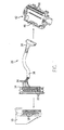
- Fig. 1 shows an input/output (I/O) module 10 with a removable face plate 14.
- the I/O module 10 includes a plurality of pins 1.8 and the removable face plate 14 includes a matching number of screw connections 22 that interface with the pins 18 when the removable face plate 14 is installed on the I/O module 10.
- a prewired cable 26 includes a cable connector 30, a plurality of wires 34, and a sheathing 38 surrounding the wires 34.
- the cable connector 30 includes a plurality of pins (not shown) each associated and in isolated communication with a corresponding wire 34.
- An interface module (IFM) 42 includes a socket 46 for receiving the cable connector 30, and a plurality of connection points 50.
- the socket 46 includes a plurality of pin receiving sockets (not shown), each associated with a pin of the cable connector and in communication with a corresponding connection point 50.
- the prewired cable 26 is arranged such that individual wires 34 may be wired as desired to the screw connections 22 of the I/O module 10 and easily communicated to the IFM 42 via the cable connection 30 and the socket 46. Such an arrangement simplifies a wiring cabinet or enclosure and makes instillation more reliable while increasing installation speed. Numerous advantages exist for using prewired cables, as is well known in the art.
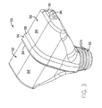
- the cable connector 54 includes a first shell element 58, a second shell element 62, and a strain relief element 66.
- the first and second shell elements 58, 62 may be constructed of Valox 357 or other U/L recognized material for electrical connectors.
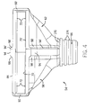
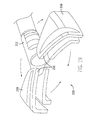
- Fig. 12 shows the first shell element 58 in detail.
- the first shell element 58 includes a front or connection aperture 70 arranged to receive a pin block, or another connection block 71 such as a pin receiving block (see Fig. 18 , the connection block 71 is shown in broken lines in Fig. 2 ).
- the connection block 71 includes a plurality of connection elements each associated with a single wire 34 of the cable 26 and insulated from the other connection elements. Connection blocks 71 are well known in the art and any desired block 71 may be suitably adapted for use with the inventive cable connector 54. For example, 20 pin and 40 pin connector blocks 71 may be used. Inward from the connection aperture 70 are arranged a pair of projections 72. When installed, the connection block 71 would abut the projections 72.
- the first shell element 58 also includes a bottom or cable aperture 74 arranged to receive the strain relief element 66. Adjacent the cable aperture 74 is a collar recess 78 of slightly larger diameter than the cable aperture 74.
- connection aperture 70 Between the connection aperture 70 and the cable aperture 74, a body cavity is defined by walls 82. The space within the body cavity provides room for the connection of wires to the connection block 71.
- An outside surface 84 of the first shell element 58 includes a T-slot 86 arranged on a side surface substantially adjacent the connection aperture 70.
- the outside surface 84 also defines a guide portion 90 that aids in the installation of the cable connector 54 into the socket 46, and a raised rib 94 on both a top side of the outside surface 84 and an underside of the outside surface 84.
- a fillet 98 is positioned between the raised ribs 94 and the outside surface 84.
- Coupling recesses 102 are defined in the raised ribs 94 and lined with energy concentrator ribs 106.
- the illustrated energy concentrator ribs 106 are triangular in cross section and extend the full depth of the coupling recess 102.
- the coupling recesses 102 terminate at a connection wall 110 adjacent the connection aperture 70 of the first shell element 58, and in a cable wall 114 adjacent the cable aperture 74.
- the rightmost end of the first shell element 58 as viewed in Fig. 12 is not enclosed by a wall but is open.
- the inside extremity is defined by an inside surface 118 of the raised ribs 94.
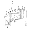
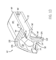
- Fig. 13 shows the second shell element 62 in detail.
- the second shell element 62 includes a front or connection aperture 70' that, together with the connection aperture 70 of the first shell element 58, receives the connection block 71 (see Fig. 18 ). Inward from the connection aperture 70' are arranged a pair of projections 72'. When installed, the connection block 71 would abut the projections 72'.
- the second shell element 62 also includes a bottom or cable aperture 74' arranged to receive the strain relief element 66. Adjacent the cable aperture 74' is a collar recess 78' of slightly larger diameter than the cable aperture 74'.
- connection aperture 70' Between the connection aperture 70' and the cable aperture 74', a body cavity is defined by walls 82'. The space within the body cavity provides room for the connection of wires to the connection block 71.
- An outside surface 84' of the second shell element 62 includes a T-slot 86' arranged on a side surface substantially adjacent the connection aperture 70'.
- the outside surface 84' also defines a guide portion 90' that aids in the installation of the cable connector 54 into the socket 46, and a raised rib 94' on both a top side of the outside surface 84' and an underside of the outside surface 84'.
- a fillet 98' is positioned between the raised ribs 94' and the outside surface 84'.
- Projections 122 extend from the raised ribs 94' and are sized to be received in the recesses 102 of the first shell element 58 and to contact the energy concentrator ribs 106.
- the projections 122 arc arranged such that the projections are received within the connection wall 110 and the cable wall 114.
- a cable wall 114' is formed in the second shell element 62 corresponding with the cable wall 114 of the first shell element 58.
- the leftmost end of the second shell element 62 as viewed in Fig. 13 is not enclosed by a wall but is open.
- the inside extremity is defined by an inside surface 126 of the raised ribs 94'.
- the inside surface 118 of the first shell element 58 abuts the inside surface 126 of the second shell element 62 when the cable connector 54 is assembled.
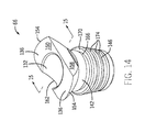
- the strain relief element 66 includes a cable aperture 132 sized to receive the cable 26, two wing portions 136, a compression ring portion 142, and a flexible skirt 146.
- the cable aperture 132 is sized such that the sheathing 38 of the cable 26 is in an interference fit relationship with the cable aperture 132. That is to say, a force must be used to install the strain relief element 66 onto the cable 26.
- the cable aperture 132 is sized for a specific cable 26 such that the interference fit can be controlled.
- the wing portions 136 define a top surface 150 of the strain relief element 66 and extend to a wing diameter 154 that can be concentric with the cable aperture 132. From the wing diameter 154, the wing portions 136 extend downward at an oblique angle to the compression ring portion 142.
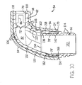
- a front surface 158 and a back surface 162 of the strain relief element 66 are shaped such that they fit within the body cavity of the first and second shell elements 58, 62 when the cable connector 54 is assembled (see Fig. 10 ).
- the compression ring portion 142 defines a diameter that is larger than a diameter of the collar recesses 78, 78' of the first and second shell elements 58, 62 when the cable connector 54 is assembled.
- a height of the compression ring portion 142 is arranged to substantially fit within a height of the collar recesses 78, 78' of the first and second shell elements 58, 62.
- a recess 166 that receives the cable walls 114, 114' of the first and second shell elements 58, 62 when the cable connector 54 is assembled to maintain the strain relief element 66 in the assembly.
- An upper surface 170 of the flexible skirt 146 abuts the bottom of the cable walls 114, 114' of the first and second shell elements 58, 62 when the cable connector 54 is assembled.
- the flexible skirt 146 defines a plurality of ribs or projections 174 and is able to flex with the movement of the cable 26 while supporting the cable 26 and providing support.
- Fig. 19 shows an alternate construction of a cable connector 200 according to the invention.
- the cable connector 200 includes a first shell element 204 and a second shell element 208 coupled to a strain relief element 212 via living springs 216.
- the illustrated cable connector 200 is formed as a single piece.
- the two shell elements 204, 208 are rotated into engagement as shown by the arrows in Fig. 19 . Once engaged, the two shell elements 204, 208 may be sonically welded together to complete assembly of the cable connector 200.
- Fig. 20 shows an alternate construction of a cable connector 300 according to the invention.
- the illustrated cable connector 300 includes a first shell element 304 and a second shell element 308.
- Each shell element includes a side aperture 312 (only the side aperture 312 of the second shell element 308 is visible).
- a strain relief element 316 includes two arms 320 that are sized to engage the side apertures 312 of the first and second shell elements 304, 308.
- the two shell elements 304, 308 may be brought together as shown by the arrows in Fig. 20 and sonically welded together. As discussed above, other joining techniques and methods may be used as desired.
- a cable 26 is selected with the desired number of conductors or wires 34 and the desired sheathing 38.
- the strain relief element 66 is then forced onto the cable sheathing 38.
- the cable aperture 132 should snugly engage the sheathing 38.
- the wires 34 are then fixed to the desired pins on the connection block 71.
- connection block 71 With the connection block 71 wired and the strain relief element 66 mounted on the sheathing 38, the first and second shell elements 58, 62 arc brought together from opposing directions to close around the strain relief element 66, the wires 34, and the connection block 71.
- the recess 166 of the strain relief element 66 is engaged by the cable walls 114, 114' of the first and second shell elements 58, 62 while the compression ring portion 142 is compressed by the collar recesses 78, 78' of the first and second shell elements 58, 62.
- the compression increases the friction force exerted on the sheathing and helps maintain the cable 26 in position relative to the strain relief element 66.
- the projections 122 of the second shell element 62 are received within the recesses 102 of the first shell element 58 with the energy concentrator ribs 106 engaging the projections 122.
- the joint can be sonic welded together.
- Other connection methods are possible. For example, an epoxy or adhesive may be used.
- the energy concentrator ribs 106 aid the sonic welding and provide a superior joint.
- the strain relief element 66 maintains the cable 26 in position via friction in the cable aperture 132 and via action of the wing portions 136.
- the wing portions 136 may flex inward with the pulling force, thereby applying a large friction force and constricting about the cable 26.
- a twisting action on the cable 26 will cause the wing portions 136 to flex and also increase the friction force, thereby resisting movement. This flexing action inhibits removal or slippage of the cable 26.
- the above described invention provides an easily customizable cable connector.
- the body cavity within the first and second shell elements 58, 62 may not be filled with polymer or other substance and is not subject to electrical crossover, interference, or accidental conduction between wires 34 or pins.
- the cable connector 54 is easy to assemble for various connector blocks or pin arrangements. Further, the diameter of cable used with the cable connector 54 can easily be changed by simply altering the diameter of the cable aperture 132 in the strain relief element 66.
- Fig. 3 is a rear perspective view of the cable connector 54.
- Fig. 4 is a front view of the cable connector 54.
- Fig. 5 is a rear view of the cable connector 54.
- Fig. 6 is a left side view of the cable connector 54.
- Fig. 7 is a right side view of the cable connector 54.
- Fig. 8 is a top view of the cable connector 54.
- Fig. 9 is a bottom view of the cable connector 54.
- Fig. 10 is a section view of the cable connector 54 taken along line 10-10 in Fig. 8 .
- Fig. 11 is a plan view of a connection profile of the cable connector 54.
- Fig. 15 is a section view of the strain relief element 66.
- Fig. 16 is a front view of the strain relief element 66.
- Fig. 17 is a top view of the strain relief element 66.
- the cable connector 54 could have a different outward appearance, or be a straight connector.
- Other constructions are possible in view of the following claims. The following is a list of further preferred embodiments of the invention:
Landscapes
- Engineering & Computer Science (AREA)
- Manufacturing & Machinery (AREA)
- Details Of Connecting Devices For Male And Female Coupling (AREA)
Applications Claiming Priority (1)
| Application Number | Priority Date | Filing Date | Title |
|---|---|---|---|
| US13/753,233 US8939788B2 (en) | 2013-01-29 | 2013-01-29 | Cable connector |
Publications (2)
| Publication Number | Publication Date |
|---|---|
| EP2760084A1 true EP2760084A1 (de) | 2014-07-30 |
| EP2760084B1 EP2760084B1 (de) | 2017-08-16 |
Family
ID=50002603
Family Applications (1)
| Application Number | Title | Priority Date | Filing Date |
|---|---|---|---|
| EP14153000.6A Active EP2760084B1 (de) | 2013-01-29 | 2014-01-29 | Kabelverbinder |
Country Status (4)
| Country | Link |
|---|---|
| US (1) | US8939788B2 (de) |
| EP (1) | EP2760084B1 (de) |
| CN (1) | CN103972707B (de) |
| BR (1) | BR102014002237A2 (de) |
Families Citing this family (6)
| Publication number | Priority date | Publication date | Assignee | Title |
|---|---|---|---|---|
| WO2016028977A1 (en) * | 2014-08-21 | 2016-02-25 | Fci Asia Pte. Ltd | Strain relief assembly for conductive cables |
| CN106299854A (zh) * | 2016-08-24 | 2017-01-04 | 西安艾力特电子实业有限公司 | 一种连接器薄壁压配防裂结构 |
| JP6764899B2 (ja) * | 2018-06-15 | 2020-10-07 | 矢崎総業株式会社 | コネクタ |
| JP7425972B2 (ja) * | 2020-07-14 | 2024-02-01 | 住友電装株式会社 | 電線カバー |
| DE202021103424U1 (de) * | 2021-06-25 | 2021-07-30 | Siemens Healthcare Gmbh | Zugentlastungseinrichtung, Verbindungsanordnung und medizinische Einrichtung |
| JP7632147B2 (ja) * | 2021-07-19 | 2025-02-19 | 住友電装株式会社 | 電線カバー及び配線部材 |
Citations (4)
| Publication number | Priority date | Publication date | Assignee | Title |
|---|---|---|---|---|
| US5749746A (en) * | 1995-09-26 | 1998-05-12 | Hon Hai Precision Ind. Co., Ltd. | Cable connector structure |
| EP1134851A1 (de) * | 2000-03-10 | 2001-09-19 | F.C.I. - Framatome Connectors International | Eingangs-/Ausgangs-Steckverbinder |
| US20040267109A1 (en) * | 2003-06-27 | 2004-12-30 | Michael Dancel | Housing for a thin active probe |
| US20050070148A1 (en) * | 2003-09-26 | 2005-03-31 | Hongbo Zhang | I/O connector with lock-release mechanism |
Family Cites Families (18)
| Publication number | Priority date | Publication date | Assignee | Title |
|---|---|---|---|---|
| US4422706A (en) * | 1981-06-08 | 1983-12-27 | Power Distribution Products, Inc. | Electrical connector plug with receptacle assembly |
| JP2515735Y2 (ja) * | 1990-11-21 | 1996-10-30 | 住友電装株式会社 | ワイヤーハーネスのコネクタカバー |
| BR9401351A (pt) * | 1994-03-30 | 1994-10-11 | Helio Lanfranchi Seabra | Aperfeiçoamento introduzido em trava de conexão para tubos de pequenos diâmetros, tipo push-in. |
| GB9516886D0 (en) * | 1995-08-17 | 1995-10-18 | Amp Great Britain | Crimpable strain relief ferrule having a retention tab thereupon |
| US5831815A (en) * | 1997-03-31 | 1998-11-03 | The Whitaker Corporation | Programmable backshell for an electrical connector |
| DE20013282U1 (de) * | 2000-08-02 | 2001-12-13 | Robert Bosch Gmbh, 70469 Stuttgart | Kabelbaumstecker mit einer Fixiereinrichtung für den Kabelbaum |
| US6688905B2 (en) * | 2001-04-09 | 2004-02-10 | Roger Williams | Field attachable electrical connector and self-tightening method of strain relief |
| US6416351B1 (en) * | 2001-04-18 | 2002-07-09 | Chi-Wen Chen | Power supply cord positioning device for a lighting unit |
| FR2843428B1 (fr) * | 2002-08-09 | 2005-04-29 | Valeo Securite Habitacle | Dispositif de commande perfectionne d'un module formant mecanisme de serrure |
| JP2004273135A (ja) * | 2003-03-05 | 2004-09-30 | Sumitomo Wiring Syst Ltd | コネクタ |
| JP2004288545A (ja) * | 2003-03-24 | 2004-10-14 | Yazaki Corp | コネクタ用プロテクタ |
| DE10347696A1 (de) * | 2003-10-14 | 2005-05-12 | Harting Electric Gmbh & Co Kg | Steckergehäuse mit verbesserter Kabelabdichtung |
| US7614902B2 (en) * | 2005-04-01 | 2009-11-10 | Bayco Products, Ltd. | Strain relief for fluorescent task lamp |
| JP4924889B2 (ja) * | 2007-05-09 | 2012-04-25 | 住友電装株式会社 | コネクタカバー |
| US7815445B2 (en) * | 2008-07-18 | 2010-10-19 | Hon Hai Precision Ind. Co., Ltd. | High-speed cable assembly with protective member |
| US7670169B1 (en) * | 2009-03-24 | 2010-03-02 | Taiwan Line Tek Electronics Co., Ltd. | Connecting device with cable |
| US8062049B2 (en) * | 2010-01-15 | 2011-11-22 | Tyco Electronics Corporation | Latch assembly for a connector assembly |
| US8096833B2 (en) * | 2010-01-15 | 2012-01-17 | Tyco Electronics Corporation | Plug assembly |
-
2013
- 2013-01-29 US US13/753,233 patent/US8939788B2/en active Active
-
2014
- 2014-01-28 CN CN201410042259.2A patent/CN103972707B/zh not_active Expired - Fee Related
- 2014-01-29 EP EP14153000.6A patent/EP2760084B1/de active Active
- 2014-01-29 BR BR102014002237A patent/BR102014002237A2/pt active Search and Examination
Patent Citations (4)
| Publication number | Priority date | Publication date | Assignee | Title |
|---|---|---|---|---|
| US5749746A (en) * | 1995-09-26 | 1998-05-12 | Hon Hai Precision Ind. Co., Ltd. | Cable connector structure |
| EP1134851A1 (de) * | 2000-03-10 | 2001-09-19 | F.C.I. - Framatome Connectors International | Eingangs-/Ausgangs-Steckverbinder |
| US20040267109A1 (en) * | 2003-06-27 | 2004-12-30 | Michael Dancel | Housing for a thin active probe |
| US20050070148A1 (en) * | 2003-09-26 | 2005-03-31 | Hongbo Zhang | I/O connector with lock-release mechanism |
Also Published As
| Publication number | Publication date |
|---|---|
| US20140213098A1 (en) | 2014-07-31 |
| US8939788B2 (en) | 2015-01-27 |
| CN103972707A (zh) | 2014-08-06 |
| BR102014002237A2 (pt) | 2015-11-03 |
| EP2760084B1 (de) | 2017-08-16 |
| CN103972707B (zh) | 2016-10-12 |
Similar Documents
| Publication | Publication Date | Title |
|---|---|---|
| EP2760084A1 (de) | Kabelverbinder | |
| US8062056B2 (en) | Electric wire connector for press connecting electric wires | |
| US8858271B2 (en) | Speaker interconnect | |
| CN105633705B (zh) | 具有稳定构件的连接器以及组装的方法 | |
| WO2005074056A2 (en) | Power terminal block | |
| EP2924815B1 (de) | Elektrische Vorrichtung mit einer Montageschnittstelle und einen elektrischen Modul | |
| CN101485052B (zh) | 具有屏蔽构造体的连接器装配体 | |
| CN203787681U (zh) | 线束组件 | |
| WO2021093071A1 (zh) | 一种防水接头与水上运动装置 | |
| EP3593417B1 (de) | Elektrischer stecker mit spezifischer erdung von aussenteilen | |
| JP3125508U (ja) | 基板に対する基板用コネクタの改良構造 | |
| JP3183082U (ja) | 超音波センサー装置 | |
| WO2007016072A3 (en) | Submersible electrical connector | |
| GB2496438A (en) | Electrical faceplate plugging into back box | |
| KR100965367B1 (ko) | 전원 연결 기구 | |
| CN203983634U (zh) | 电连接器 | |
| EP2615693B1 (de) | Leicht zu installierende und zu wartende wasserdichte steckdosen- und steckeranordnung | |
| US20200244055A1 (en) | Cable tray splice | |
| CN110635328A (zh) | 一种转接连接器以及包含该转接连接器的连接器组件 | |
| CN108683022A (zh) | 一种防水式墙插以及接电设备 | |
| CN109326926A (zh) | 一种鞍形端子及开关插座 | |
| EP3001513B1 (de) | Elektrische Verbindungsvorrichtung, Verbinderkit und Verfahren zum elektrischen Verbinden von zwei Vorrichtungen | |
| CN207781945U (zh) | 连接线组件和料理机 | |
| CN204230849U (zh) | 用于高压接线盒的高压互锁结构及相应高压接线盒 | |
| CN105449458B (zh) | 三段式接插件 |
Legal Events
| Date | Code | Title | Description |
|---|---|---|---|
| PUAI | Public reference made under article 153(3) epc to a published international application that has entered the european phase |
Free format text: ORIGINAL CODE: 0009012 |
|
| 17P | Request for examination filed |
Effective date: 20140129 |
|
| AK | Designated contracting states |
Kind code of ref document: A1 Designated state(s): AL AT BE BG CH CY CZ DE DK EE ES FI FR GB GR HR HU IE IS IT LI LT LU LV MC MK MT NL NO PL PT RO RS SE SI SK SM TR |
|
| AX | Request for extension of the european patent |
Extension state: BA ME |
|
| R17P | Request for examination filed (corrected) |
Effective date: 20150116 |
|
| RBV | Designated contracting states (corrected) |
Designated state(s): AL AT BE BG CH CY CZ DE DK EE ES FI FR GB GR HR HU IE IS IT LI LT LU LV MC MK MT NL NO PL PT RO RS SE SI SK SM TR |
|
| 17Q | First examination report despatched |
Effective date: 20160203 |
|
| RIC1 | Information provided on ipc code assigned before grant |
Ipc: H01R 13/504 20060101AFI20170320BHEP Ipc: H01R 43/26 20060101ALI20170320BHEP Ipc: H01R 13/516 20060101ALI20170320BHEP Ipc: H01R 13/585 20060101ALN20170320BHEP Ipc: H01R 13/56 20060101ALN20170320BHEP |
|
| RIC1 | Information provided on ipc code assigned before grant |
Ipc: H01R 13/516 20060101ALI20170324BHEP Ipc: H01R 13/585 20060101ALN20170324BHEP Ipc: H01R 13/56 20060101ALN20170324BHEP Ipc: H01R 43/26 20060101ALI20170324BHEP Ipc: H01R 13/504 20060101AFI20170324BHEP |
|
| GRAP | Despatch of communication of intention to grant a patent |
Free format text: ORIGINAL CODE: EPIDOSNIGR1 |
|
| RIC1 | Information provided on ipc code assigned before grant |
Ipc: H01R 13/516 20060101ALI20170413BHEP Ipc: H01R 13/504 20060101AFI20170413BHEP Ipc: H01R 43/26 20060101ALI20170413BHEP Ipc: H01R 13/585 20060101ALN20170413BHEP Ipc: H01R 13/56 20060101ALN20170413BHEP |
|
| INTG | Intention to grant announced |
Effective date: 20170509 |
|
| GRAS | Grant fee paid |
Free format text: ORIGINAL CODE: EPIDOSNIGR3 |
|
| GRAA | (expected) grant |
Free format text: ORIGINAL CODE: 0009210 |
|
| AK | Designated contracting states |
Kind code of ref document: B1 Designated state(s): AL AT BE BG CH CY CZ DE DK EE ES FI FR GB GR HR HU IE IS IT LI LT LU LV MC MK MT NL NO PL PT RO RS SE SI SK SM TR |
|
| REG | Reference to a national code |
Ref country code: GB Ref legal event code: FG4D |
|
| REG | Reference to a national code |
Ref country code: CH Ref legal event code: EP |
|
| REG | Reference to a national code |
Ref country code: IE Ref legal event code: FG4D |
|
| REG | Reference to a national code |
Ref country code: AT Ref legal event code: REF Ref document number: 919931 Country of ref document: AT Kind code of ref document: T Effective date: 20170915 |
|
| REG | Reference to a national code |
Ref country code: DE Ref legal event code: R096 Ref document number: 602014013071 Country of ref document: DE |
|
| REG | Reference to a national code |
Ref country code: NL Ref legal event code: MP Effective date: 20170816 |
|
| REG | Reference to a national code |
Ref country code: LT Ref legal event code: MG4D |
|
| REG | Reference to a national code |
Ref country code: AT Ref legal event code: MK05 Ref document number: 919931 Country of ref document: AT Kind code of ref document: T Effective date: 20170816 |
|
| REG | Reference to a national code |
Ref country code: FR Ref legal event code: PLFP Year of fee payment: 5 |
|
| PG25 | Lapsed in a contracting state [announced via postgrant information from national office to epo] |
Ref country code: AT Free format text: LAPSE BECAUSE OF FAILURE TO SUBMIT A TRANSLATION OF THE DESCRIPTION OR TO PAY THE FEE WITHIN THE PRESCRIBED TIME-LIMIT Effective date: 20170816 Ref country code: NL Free format text: LAPSE BECAUSE OF FAILURE TO SUBMIT A TRANSLATION OF THE DESCRIPTION OR TO PAY THE FEE WITHIN THE PRESCRIBED TIME-LIMIT Effective date: 20170816 Ref country code: NO Free format text: LAPSE BECAUSE OF FAILURE TO SUBMIT A TRANSLATION OF THE DESCRIPTION OR TO PAY THE FEE WITHIN THE PRESCRIBED TIME-LIMIT Effective date: 20171116 Ref country code: SE Free format text: LAPSE BECAUSE OF FAILURE TO SUBMIT A TRANSLATION OF THE DESCRIPTION OR TO PAY THE FEE WITHIN THE PRESCRIBED TIME-LIMIT Effective date: 20170816 Ref country code: FI Free format text: LAPSE BECAUSE OF FAILURE TO SUBMIT A TRANSLATION OF THE DESCRIPTION OR TO PAY THE FEE WITHIN THE PRESCRIBED TIME-LIMIT Effective date: 20170816 Ref country code: LT Free format text: LAPSE BECAUSE OF FAILURE TO SUBMIT A TRANSLATION OF THE DESCRIPTION OR TO PAY THE FEE WITHIN THE PRESCRIBED TIME-LIMIT Effective date: 20170816 |
|
| PG25 | Lapsed in a contracting state [announced via postgrant information from national office to epo] |
Ref country code: GR Free format text: LAPSE BECAUSE OF FAILURE TO SUBMIT A TRANSLATION OF THE DESCRIPTION OR TO PAY THE FEE WITHIN THE PRESCRIBED TIME-LIMIT Effective date: 20171117 Ref country code: ES Free format text: LAPSE BECAUSE OF FAILURE TO SUBMIT A TRANSLATION OF THE DESCRIPTION OR TO PAY THE FEE WITHIN THE PRESCRIBED TIME-LIMIT Effective date: 20170816 Ref country code: IS Free format text: LAPSE BECAUSE OF FAILURE TO SUBMIT A TRANSLATION OF THE DESCRIPTION OR TO PAY THE FEE WITHIN THE PRESCRIBED TIME-LIMIT Effective date: 20171216 Ref country code: BG Free format text: LAPSE BECAUSE OF FAILURE TO SUBMIT A TRANSLATION OF THE DESCRIPTION OR TO PAY THE FEE WITHIN THE PRESCRIBED TIME-LIMIT Effective date: 20171116 Ref country code: RS Free format text: LAPSE BECAUSE OF FAILURE TO SUBMIT A TRANSLATION OF THE DESCRIPTION OR TO PAY THE FEE WITHIN THE PRESCRIBED TIME-LIMIT Effective date: 20170816 Ref country code: LV Free format text: LAPSE BECAUSE OF FAILURE TO SUBMIT A TRANSLATION OF THE DESCRIPTION OR TO PAY THE FEE WITHIN THE PRESCRIBED TIME-LIMIT Effective date: 20170816 Ref country code: PL Free format text: LAPSE BECAUSE OF FAILURE TO SUBMIT A TRANSLATION OF THE DESCRIPTION OR TO PAY THE FEE WITHIN THE PRESCRIBED TIME-LIMIT Effective date: 20170816 |
|
| PG25 | Lapsed in a contracting state [announced via postgrant information from national office to epo] |
Ref country code: CZ Free format text: LAPSE BECAUSE OF FAILURE TO SUBMIT A TRANSLATION OF THE DESCRIPTION OR TO PAY THE FEE WITHIN THE PRESCRIBED TIME-LIMIT Effective date: 20170816 Ref country code: RO Free format text: LAPSE BECAUSE OF FAILURE TO SUBMIT A TRANSLATION OF THE DESCRIPTION OR TO PAY THE FEE WITHIN THE PRESCRIBED TIME-LIMIT Effective date: 20170816 Ref country code: DK Free format text: LAPSE BECAUSE OF FAILURE TO SUBMIT A TRANSLATION OF THE DESCRIPTION OR TO PAY THE FEE WITHIN THE PRESCRIBED TIME-LIMIT Effective date: 20170816 |
|
| REG | Reference to a national code |
Ref country code: DE Ref legal event code: R097 Ref document number: 602014013071 Country of ref document: DE |
|
| PG25 | Lapsed in a contracting state [announced via postgrant information from national office to epo] |
Ref country code: IT Free format text: LAPSE BECAUSE OF FAILURE TO SUBMIT A TRANSLATION OF THE DESCRIPTION OR TO PAY THE FEE WITHIN THE PRESCRIBED TIME-LIMIT Effective date: 20170816 Ref country code: EE Free format text: LAPSE BECAUSE OF FAILURE TO SUBMIT A TRANSLATION OF THE DESCRIPTION OR TO PAY THE FEE WITHIN THE PRESCRIBED TIME-LIMIT Effective date: 20170816 Ref country code: SK Free format text: LAPSE BECAUSE OF FAILURE TO SUBMIT A TRANSLATION OF THE DESCRIPTION OR TO PAY THE FEE WITHIN THE PRESCRIBED TIME-LIMIT Effective date: 20170816 Ref country code: SM Free format text: LAPSE BECAUSE OF FAILURE TO SUBMIT A TRANSLATION OF THE DESCRIPTION OR TO PAY THE FEE WITHIN THE PRESCRIBED TIME-LIMIT Effective date: 20170816 |
|
| PLBE | No opposition filed within time limit |
Free format text: ORIGINAL CODE: 0009261 |
|
| STAA | Information on the status of an ep patent application or granted ep patent |
Free format text: STATUS: NO OPPOSITION FILED WITHIN TIME LIMIT |
|
| 26N | No opposition filed |
Effective date: 20180517 |
|
| PG25 | Lapsed in a contracting state [announced via postgrant information from national office to epo] |
Ref country code: SI Free format text: LAPSE BECAUSE OF FAILURE TO SUBMIT A TRANSLATION OF THE DESCRIPTION OR TO PAY THE FEE WITHIN THE PRESCRIBED TIME-LIMIT Effective date: 20170816 |
|
| REG | Reference to a national code |
Ref country code: CH Ref legal event code: PL |
|
| PG25 | Lapsed in a contracting state [announced via postgrant information from national office to epo] |
Ref country code: LU Free format text: LAPSE BECAUSE OF NON-PAYMENT OF DUE FEES Effective date: 20180129 |
|
| REG | Reference to a national code |
Ref country code: IE Ref legal event code: MM4A |
|
| REG | Reference to a national code |
Ref country code: BE Ref legal event code: MM Effective date: 20180131 |
|
| PG25 | Lapsed in a contracting state [announced via postgrant information from national office to epo] |
Ref country code: LI Free format text: LAPSE BECAUSE OF NON-PAYMENT OF DUE FEES Effective date: 20180131 Ref country code: CH Free format text: LAPSE BECAUSE OF NON-PAYMENT OF DUE FEES Effective date: 20180131 Ref country code: BE Free format text: LAPSE BECAUSE OF NON-PAYMENT OF DUE FEES Effective date: 20180131 |
|
| PG25 | Lapsed in a contracting state [announced via postgrant information from national office to epo] |
Ref country code: IE Free format text: LAPSE BECAUSE OF NON-PAYMENT OF DUE FEES Effective date: 20180129 |
|
| PG25 | Lapsed in a contracting state [announced via postgrant information from national office to epo] |
Ref country code: MC Free format text: LAPSE BECAUSE OF FAILURE TO SUBMIT A TRANSLATION OF THE DESCRIPTION OR TO PAY THE FEE WITHIN THE PRESCRIBED TIME-LIMIT Effective date: 20170816 |
|
| PG25 | Lapsed in a contracting state [announced via postgrant information from national office to epo] |
Ref country code: MT Free format text: LAPSE BECAUSE OF NON-PAYMENT OF DUE FEES Effective date: 20180129 |
|
| PG25 | Lapsed in a contracting state [announced via postgrant information from national office to epo] |
Ref country code: TR Free format text: LAPSE BECAUSE OF FAILURE TO SUBMIT A TRANSLATION OF THE DESCRIPTION OR TO PAY THE FEE WITHIN THE PRESCRIBED TIME-LIMIT Effective date: 20170816 |
|
| PG25 | Lapsed in a contracting state [announced via postgrant information from national office to epo] |
Ref country code: HU Free format text: LAPSE BECAUSE OF FAILURE TO SUBMIT A TRANSLATION OF THE DESCRIPTION OR TO PAY THE FEE WITHIN THE PRESCRIBED TIME-LIMIT; INVALID AB INITIO Effective date: 20140129 Ref country code: PT Free format text: LAPSE BECAUSE OF FAILURE TO SUBMIT A TRANSLATION OF THE DESCRIPTION OR TO PAY THE FEE WITHIN THE PRESCRIBED TIME-LIMIT Effective date: 20170816 |
|
| PG25 | Lapsed in a contracting state [announced via postgrant information from national office to epo] |
Ref country code: CY Free format text: LAPSE BECAUSE OF FAILURE TO SUBMIT A TRANSLATION OF THE DESCRIPTION OR TO PAY THE FEE WITHIN THE PRESCRIBED TIME-LIMIT Effective date: 20170816 Ref country code: MK Free format text: LAPSE BECAUSE OF NON-PAYMENT OF DUE FEES Effective date: 20170816 Ref country code: HR Free format text: LAPSE BECAUSE OF FAILURE TO SUBMIT A TRANSLATION OF THE DESCRIPTION OR TO PAY THE FEE WITHIN THE PRESCRIBED TIME-LIMIT Effective date: 20170816 |
|
| PG25 | Lapsed in a contracting state [announced via postgrant information from national office to epo] |
Ref country code: AL Free format text: LAPSE BECAUSE OF FAILURE TO SUBMIT A TRANSLATION OF THE DESCRIPTION OR TO PAY THE FEE WITHIN THE PRESCRIBED TIME-LIMIT Effective date: 20170816 |
|
| PGFP | Annual fee paid to national office [announced via postgrant information from national office to epo] |
Ref country code: GB Payment date: 20221221 Year of fee payment: 10 Ref country code: FR Payment date: 20221220 Year of fee payment: 10 |
|
| P01 | Opt-out of the competence of the unified patent court (upc) registered |
Effective date: 20230404 |
|
| GBPC | Gb: european patent ceased through non-payment of renewal fee |
Effective date: 20240129 |
|
| PG25 | Lapsed in a contracting state [announced via postgrant information from national office to epo] |
Ref country code: GB Free format text: LAPSE BECAUSE OF NON-PAYMENT OF DUE FEES Effective date: 20240129 |
|
| PG25 | Lapsed in a contracting state [announced via postgrant information from national office to epo] |
Ref country code: FR Free format text: LAPSE BECAUSE OF NON-PAYMENT OF DUE FEES Effective date: 20240131 |
|
| PG25 | Lapsed in a contracting state [announced via postgrant information from national office to epo] |
Ref country code: GB Free format text: LAPSE BECAUSE OF NON-PAYMENT OF DUE FEES Effective date: 20240129 Ref country code: FR Free format text: LAPSE BECAUSE OF NON-PAYMENT OF DUE FEES Effective date: 20240131 |
|
| PGFP | Annual fee paid to national office [announced via postgrant information from national office to epo] |
Ref country code: DE Payment date: 20251217 Year of fee payment: 13 |