EP2759436B2 - Entlüftungsventil - Google Patents
Entlüftungsventil Download PDFInfo
- Publication number
- EP2759436B2 EP2759436B2 EP13192514.1A EP13192514A EP2759436B2 EP 2759436 B2 EP2759436 B2 EP 2759436B2 EP 13192514 A EP13192514 A EP 13192514A EP 2759436 B2 EP2759436 B2 EP 2759436B2
- Authority
- EP
- European Patent Office
- Prior art keywords
- float
- vent valve
- vent
- seal
- opening
- Prior art date
- Legal status (The legal status is an assumption and is not a legal conclusion. Google has not performed a legal analysis and makes no representation as to the accuracy of the status listed.)
- Active
Links
Images


Classifications
-
- B—PERFORMING OPERATIONS; TRANSPORTING
- B60—VEHICLES IN GENERAL
- B60K—ARRANGEMENT OR MOUNTING OF PROPULSION UNITS OR OF TRANSMISSIONS IN VEHICLES; ARRANGEMENT OR MOUNTING OF PLURAL DIVERSE PRIME-MOVERS IN VEHICLES; AUXILIARY DRIVES FOR VEHICLES; INSTRUMENTATION OR DASHBOARDS FOR VEHICLES; ARRANGEMENTS IN CONNECTION WITH COOLING, AIR INTAKE, GAS EXHAUST OR FUEL SUPPLY OF PROPULSION UNITS IN VEHICLES
- B60K15/00—Arrangement in connection with fuel supply of combustion engines or other fuel consuming energy converters, e.g. fuel cells; Mounting or construction of fuel tanks
- B60K15/03—Fuel tanks
- B60K15/035—Fuel tanks characterised by venting means
- B60K15/03519—Valve arrangements in the vent line
Definitions
- the present invention relates to a vent valve for venting a liquid tank in a motor vehicle.
- the publication EP 2 008 857 A1 describes, for example, a fuel tank for a motor vehicle with a valve housing and a vent having vent valve, which is inserted in an upper opening of the tank and protrudes into the tank interior and in which the wall of the valve housing is penetrated by a wall opening.
- the valve housing is a movable between a rest position and a closed position float.
- the object is achieved by a vent valve for venting a liquid tank in a motor vehicle when refueling via a vent opening, with a float in a float chamber for closing the vent opening and a line connection for supplying liquid from the liquid tank to the float chamber.
- the liquid tank is, for example, a tank for an aqueous urea solution.
- the vent valve can be arranged outside of the liquid tank and damage to the vent valve is prevented by a moving liquid.
- the function of the vent valve is not disturbed by movements of the liquid in the liquid tank.
- the float comprises a cup-shaped float body.
- the technical advantage is achieved that the float can be made with little effort and weight and forms an air bubble inside the float body, which presses the float upon entry of liquid into the float chamber against the vent.
- the float includes a float seal for sealing the vent.
- a float seal for sealing the vent.
- the float comprises a seal carrier for fastening the float seal.
- the seal carrier is attached to the float with a freedom of movement.
- the float seal includes a seal opening for passing air from the float chamber.
- the float includes a mandrel for closing the seal opening.
- the float chamber comprises a guide insert for guiding the float.
- the guide insert forms a stop for the float.
- the vent is covered on an exit side by an elastic membrane.
- the elastic membrane is arranged such that it generates an air gap at an overpressure in the venting valve, from which the air from the Bleed valve can escape.
- the elastic membrane comprises ventilation slots. At a negative pressure in the valve interior, the ambient air via the louvers in the membrane in the vent valve can occur for the purpose of pressure equalization. As a result, an air exchange with the valve interior is reduced to a minimum, so that, for example, dehydration and the associated crystallization of urea are prevented. In this way, the functionality of the vent valve can be ensured.
- the elastic membrane is circular.
- the technical advantage is achieved that an open air gap is generated on all sides and the air can escape at a high rate from the vent valve.
- the elastic membrane is fixed in the middle of the vent opening.
- the technical advantage is achieved that a present overpressure can lift all sides of the elastic membrane.
- the venting valve comprises a protective cap for preventing the penetration of dirt particles into the venting opening.
- the float chamber has a cylindrical shape.
- the vent valve includes a circular seal plate in which the vent opening is centrally located.
- the venting valve comprises a flow plate for breaking a liquid jet entering the float chamber.
- the vent valve comprises a secondary nozzle for a further air exchange.
- Fig. 1 shows a perspective view and an exploded view of the vent valve 100.
- the vent valve 100 is inserted into the tank vent line.
- the venting valve 100 makes it possible for the gas volume to be displaced to escape from the liquid tank in the event of overpressure, for example resulting from refueling or differences in air pressure.
- a shutdown / termination of a dispensing valve automatic is effected at a defined filling amount by the vent valve 100.
- the air in the liquid tank is displaced by the filled liquid.
- the liquid tank is filled with a high filling rate of, for example, 40 l / min, the displaced air flows out of the liquid tank at substantially the same rate.
- the vent valve 100 should be designed for the filling rate used.
- the vent valve 100 comprises a cup-shaped housing part 131, in which a nozzle as a line connection 109 for supplying liquid from the liquid tank to the vent valve and a side sockets 129 are formed for a further air exchange, for example, when refueling the liquid tank with a screwed bottle.
- a nozzle as a line connection 109 for supplying liquid from the liquid tank to the vent valve
- a side sockets 129 are formed for a further air exchange, for example, when refueling the liquid tank with a screwed bottle.
- liquid enters the deaeration valve 100 via a liquid line connected to the line connection 109.
- the housing part 131 forms a cylindrical float chamber 107 inside.
- the advantage is achieved that the vent valve 100 can be used outside of the liquid tank. Damage or malfunction of the vent valve 100 by moving in the liquid tank liquid can be prevented.
- a float 101 Inside the vent valve 100 is a float 101 with a float body 105, which closes a vent opening 103 when the liquid enters the vent valve 100. As a result, a first valve in the interior of the venting valve 100 is realized.
- the float body 105 is also cup-shaped and is located in the interior of the vent valve 100.
- the cup shape which is open at the bottom, forms an air trap in the interior of the float body 105 when liquid enters, causing the float body 105 to float upward and against the vent opening 103 suppressed. In this case, no more air exits through the vent opening 103 from the vent valve 100.
- the float 101 moves down again and releases the venting opening 103. In this case, the air can escape via the vent 103 from the vent valve 100 again.
- the air displaced by the liquid inside the tank exits until liquid enters the liquid line which leads to the venting valve 100 and brings the float 101 into the closed position.
- a float seal 111 for sealing the vent opening 103 is arranged.
- the float seal 111 is plate-shaped and consists of an elastic material, such as silicone.
- the float seal 111 lies in the closed position on the opposite edge surface of the vent opening 103 and closes the vent opening 103 such that no air can escape from the vent valve 100.
- the float seal 111 is attached to the float body 105 via a seal carrier 113.
- the seal carrier 113 has a central, round insertion opening into which the float seal 111 is inserted.
- the plate-shaped float seal 111 has a bead-shaped bulge, which is pressed into the insertion opening.
- four fastening arms 133 are formed on the upper side of the float body 105, which engage in the seal carrier 113.
- the fastening arms 133 are designed such that the seal carrier 113 has a certain play relative to the float body 105 and can move freely within the game.
- the clearance causes a longitudinally extending movement clearance of the seal carrier 113 with the float seal 111.
- a seal opening 115 for passing air from or into the float chamber 107 is formed in the center of the float seal 111.
- a mandrel 117 is formed on the upper side of the float body 105. In the closed position, the mandrel 117 is pressed onto the seal opening 115, so that air leakage is prevented.
- the float body 105 If the liquid level in the float chamber 107 drops, the float body 105 also sinks down due to its own weight, provided that no defined overpressure is present in the float housing. In this case, due to the play of the seal carrier 113, first the mandrel 117 is moved away from the seal opening 115, so that the seal opening 115 is released and air can pass through the seal opening 115. As a result, an excess pressure in the float chamber 107 can be reduced, which would possibly prevent the vent valve 100 from reopening.
- the cylindrical float body 105 of the float 101 is supported inside the float chamber 107 by means of a guide insert 119.
- the guide insert 119 is a plastic molded part that is inserted into the interior of the float chamber 107 and supports the movement of the float body 105.
- the guide insert 119 stabilizes the float 101 in the lateral direction with respect to the inner wall of the housing part 131 and allows movement of the float 101 in the longitudinal direction.
- the guide insert 119 forms a stop for the float body 105 so that it comes to a stop at an opening position at a predetermined position.
- the guide insert 119 comprises at least four insert legs 135 which extend in the interior of the float chamber 107 in the longitudinal direction. In the assembled state of the vent valve 100, the insert legs lie on a flow plate 127. Thereby, the advantage is achieved that the float body 105 to either side by one of the insert legs 135 is performed. In general, the number of insert legs 135 can also assume other values.
- the flow plate 127 serves to break a liquid jet entering the float chamber 107. This prevents the incoming liquid jet from directly striking the float body 105 and moving it through its mechanical impulse into the closed position.
- a plurality of sector-shaped openings are formed in the flow plate 127, through which the liquid can flow into the float chamber 107. In the middle of the flow plate 127 is no opening, so that a direct impact of the liquid jet is prevented on the float body 105.
- the flow plate 127 next to it prevents turbulence of the liquid.
- the flow plate 127 includes a number of struts which support the flow plate 127 resiliently on the bottom of the housing part 131. If the vent valve 100 is assembled and welded, a pressure is exerted on the guide insert 119 through the flow plate 127 by compressing the struts so that it is clamped without play between the flow plate 127 and a seal plate 125.
- the circular seal plate 125 includes the vent hole 103.
- the seal plate 125 is set from above on the cup-shaped housing part 131 and welded, so that the float chamber 107 is closed. The float chamber 107 is thereby closed to atmospheric pressure.
- this has a number of reinforcing struts.
- the reinforcing struts extend on the outside of the seal plate 125 and extend radially between the vent opening 103 and an outer edge of the seal plate 125.
- the outside of the vent 103 is covered by an elastic membrane 121. Via the elastic membrane 121, the air can emerge from the vent valve 100 at an overpressure. In this case, the plate or outer edge of the elastic membrane 121 is lifted upward, so that the escaping air escapes through the gap between the membrane 121 and the sealing plate 125. If there is no overpressure in the valve interior, the outer edge of the membrane 121 rests on the sealing plate 125. As a result, the valve interior is closed to the outside environment, so that there is no permanent exchange of air with the ambient air. As a result, a second valve in the interior of the vent valve 100 is realized.
- louvers in the elastic membrane 121 are designed so that they are closed with balanced pressure between the valve interior and the environment. As a result, an exchange of air with the valve interior is reduced to a minimum, so that dehydration and the associated crystallization of urea are prevented.
- the structure of the vent valve 100 is thus designed such that an air supply via slots in the membrane 121 is also realized for a negative pressure in the liquid tank. As a result, an additional valve effect is made possible. In addition, entry of impurities or dirt particles into the vent opening 103 can be prevented.
- the elastic membrane 121 is placed on a mandrel which protrudes outwardly from the center of the vent opening 103. Thereby, lateral slippage of the elastic membrane 121 can be prevented.
- a crystallization of urea in the entire vent valve can be prevented by the membrane. The prevention of crystal formation allows trouble-free operation of the vent valve 100.
- a protective cap 123 is disposed in the vent 103 for further preventing the penetration of dirt particles.
- the protective cap engages on the sealing plate 125 and simultaneously fixes the elastic membrane 121.
- the solid items from which the vent valve 100 is made are plastic moldings.
- these may be injection molded from polyamide (PA), polyoxymethylene (POM), polyolefin, or olefin-based thermoplastic elastomers (TPO).
- PA polyamide
- POM polyoxymethylene
- TPO thermoplastic elastomers
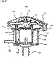
- Fig. 2 shows a cross-sectional view of the vent valve 100 with open vent 103 in the open position.
- the float 101 is in a lower position so that the float seal 111 releases the vent 103 and air can escape from the vent 103. Due to the wide opening of the vent opening 103, the venting can also take place at a high rate of, for example, 40 l / min.
- the air displaced from the liquid tank enters the float chamber 107 via the line port 109 and becomes around the float 101 before it then exits the vent 103. Thus, aeration over the elastic membrane 121 is certainly steep.
- the float 101 rests on the guide insert 119.
- individual surveys 137 are formed as support points for the float body 105 on the guide insert. These elevations 137 prevent a large-area contact of the float body 105 on the guide insert 119.
- Fig. 3 shows a cross-sectional view of the vent valve 100 with closed vent 103.
- the liquid level increases in the float chamber 107 and the float 101 is lifted to the closed position and closes by means of the float seal 111, the vent 103 against the atmospheric pressure. In this case, no air and no liquid can escape from the vent valve 100.
- the float seal 111 disposed on the float body 105 closes the vent opening 103.
- the spine 117 of the float body 105 closes the seal opening 115 of the float seal 111.
- the float chamber 107 is sealed to the outside and leakage of liquid is prevented. This then causes the shutdown or termination of the refueling process and the liquid tank is filled.
- the flow plate 127 is located below the float 101 and prevents the incoming liquid jet from directly striking the float body 105.
- the struts 139 of the flow plate 127 push the guide insert 119 for the float valve to the seal plate 125, so that the guide insert 119 is immovably disposed in the interior of the float chamber 107 and rattling noises are prevented.
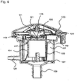
- FIG. 12 shows a cross-sectional view of the closed-seal float vent valve 100 in which the seal opening 115 in the float seal 111 is released.
- the float 101 moves down.
- the mandrel 117 of the float body 105 initially releases the central sealing opening 115 so that air can flow through the sealing opening 115 into the interior of the float chamber 107 or out of the float chamber 107.
- a pressure equalization is achieved, since otherwise the float 101 could remain in the closed position.
- the float seal 111 then falls downwards from the vent opening 103, so that it is released and air can flow outward through the vent opening 103 and the elastic membrane 121, for example in the case of a renewed one Refueling the liquid tank. There is again a pressure equalization between the liquid tank and the atmosphere.
Landscapes
- Engineering & Computer Science (AREA)
- Life Sciences & Earth Sciences (AREA)
- Sustainable Development (AREA)
- Sustainable Energy (AREA)
- Chemical & Material Sciences (AREA)
- Combustion & Propulsion (AREA)
- Transportation (AREA)
- Mechanical Engineering (AREA)
- Self-Closing Valves And Venting Or Aerating Valves (AREA)
- Float Valves (AREA)
Description
- Die vorliegende Erfindung betrifft ein Entlüftungsventil zum Entlüften eines Flüssigkeitstanks in einem Kraftfahrzeug.
- Beim Betanken eines Flüssigkeitstanks wird die Luft im Inneren des Flüssigkeitstanks durch die eingefüllte Flüssigkeit verdrängt. Um die verdrängte Luft aus dem Flüssigkeitstank abzuführen, werden spezielle Entlüftungsventile verwendet.
- Die Druckschrift
EP 2 008 857 A1 beschreibt beispielsweise einen Kraftstofftank für ein Kraftfahrzeug mit einem ein Ventilgehäuse und eine Entlüftungsöffnung aufweisenden Entlüftungsventil, das in einer oberen Öffnung des Tanks eingesetzt ist und in das Tankinnere hineinragt und bei dem die Wand des Ventilgehäuses von einer Wandöffnung durchsetzt ist. Im Ventilgehäuse befindet sich ein zwischen einer Ruhestellung und einer Schließstellung beweglicher Schwimmer. - Bei dieser Art von Flüssigkeitstank entsteht das Problem, dass das in den Tank hineinragende Entlüftungsventil Kräften ausgesetzt ist, die durch eine sich bewegende Flüssigkeit bei einer Bewegung des Fahrzeugs verursacht werden. Befinden sich in der Flüssigkeit Gegenstände, wie beispielsweise Eisschollen in einem Tank für eine wässrige Harnstofflösung, treffen diese bei einer Bewegung des Fahrzeugs auf das hervorstehende Entlüftungsventil und beschädigen dieses.
- Es ist die der Erfindung zugrundeliegende Aufgabe, die Beschädigung eines Entlüftungsventils bei einer Bewegung des Fahrzeugs zu verhindern.
- Diese Aufgabe wird durch den Gegenstand mit den Merkmalen nach dem unabhängigen Anspruch gelöst. Vorteilhafte Ausführungsformen sind Gegenstand der abhängigen Ansprüche, der Beschreibung und der Figuren.
- Gemäß einem Aspekt wird die Aufgabe durch ein Entlüftungsventil zum Entlüften eines Flüssigkeitstanks in einem Kraftfahrzeug bei einer Betankung über eine Entlüftungsöffnung gelöst, mit einem Schwimmer in einer Schwimmerkammer zum Verschließen der Entlüftungsöffnung und einem Leitungsanschluss zum Zuführen von Flüssigkeit aus dem Flüssigkeitstank zur Schwimmerkammer. Der Flüssigkeitstank ist beispielsweise ein Tank für eine wässrige Harnstofflösung.
- Durch den Leitungsanschluss wird der technische Vorteil erreicht, dass das Entlüftungsventil außerhalb des Flüssigkeitstanks angeordnet werden kann und eine Beschädigung des Entlüftungsventils durch eine sich bewegende Flüssigkeit verhindert wird. Daneben wird die Funktion des Entlüftungsventils nicht durch Bewegungen der Flüssigkeit im Flüssigkeitstank gestört.
- In einer vorteilhaften Ausführungsform des Entlüftungsventils umfasst der Schwimmer einen becherförmigen Schwimmerkörper. Dadurch wird beispielsweise der technische Vorteil erreicht, dass der Schwimmer mit geringem Aufwand und Gewicht hergestellt werden kann und sich im Inneren des Schwimmerkörpers eine Luftblase bildet, die den Schwimmer beim Eintritt von Flüssigkeit in die Schwimmerkammer gegen die Entlüftungsöffnung drückt.
- Der Schwimmer umfasst eine Schwimmerdichtung zum Abdichten der Entlüftungsöffnung. Dadurch wird beispielsweise der technische Vorteil erreicht, dass die Dichtwirkung des Entlüftungsventils verbessert wird.
- In einer weiteren vorteilhaften Ausführungsform des Entlüftungsventils umfasst der Schwimmer einen Dichtungsträger zum Befestigen der Schwimmerdichtung. Dadurch wird beispielsweise der technische Vorteil erreicht, dass die Schwimmerdichtung auf einfache Weise an dem Schwimmer befestigt werden kann.
- In einer weiteren vorteilhaften Ausführungsform des Entlüftungsventils ist der Dichtungsträger mit einem Bewegungsfreiraum an dem Schwimmer befestigt. Dadurch wird beispielsweise der technische Vorteil erreicht, dass die Schwimmerdichtung mit einem Spiel an dem Schwimmer befestigt ist und die Entlüftungsöffnung verschließt, ohne zu verkanten.
- Die Schwimmerdichtung umfasst eine Dichtungsöffnung zum Durchlassen von Luft aus der Schwimmerkammer. Dadurch wird beispielsweise der technische Vorteil erreicht, dass ein Lösen der Schwimmerdichtung aus einer geschlossenen Position erleichtert wird.
- Der Schwimmer umfasst einen Dorn zum Verschließen der Dichtungsöffnung. Dadurch wird beispielsweise der technische Vorteil erreicht, dass ein Austritt von Flüssigkeit bei ansteigendem Flüssigkeitspegel innerhalb der Schwimmerkammer verhindert wird, wohingegen bei absinkendem Flüssigkeitspegel innerhalb der Schwimmerkammer die Dichtungsöffnung freigeben wird, so dass ein Luftdurchtritt erreicht wird und ein Überdruck abgebaut werden kann.
- In einer weiteren vorteilhaften Ausführungsform des Entlüftungsventils umfasst die Schwimmerkammer einen Führungseinsatz zum Führen des Schwimmers. Dadurch wird beispielsweise der technische Vorteil erreicht, dass ein Verklemmen des Schwimmers verhindert wird.
- In einer weiteren vorteilhaften Ausführungsform des Entlüftungsventils bildet der Führungseinsatz einen Anschlag für den Schwimmer. Dadurch wird beispielsweise der technische Vorteil erreicht, dass sich der Schwimmer in der geöffneten Stellung in einer exakt definierten Lage befindet, so dass ein Schließen der Entlüftungsöffnung sichergestellt werden kann.
- Die Entlüftungsöffnung ist an einer Austrittseite von einer elastischen Membran abgedeckt. Die elastische Membran ist derart angeordnet, dass diese bei einem Überdruck im Entlüftungsventil einen Luftspalt erzeugt, aus dem die Luft aus dem Entlüftungsventil austreten kann. Die elastische Membran umfasst Lüftungsschlitze. Bei einem Unterdruck im Ventilinneren kann zum Zwecke eines Druckausgleichs die Umgebungsluft über die Luftschlitze in der Membran in das Entlüftungsventil eintreten. Hierdurch wird ein Luftaustausch mit dem Ventilinneren auf ein Minimum reduziert, so dass beispielsweise eine Austrocknung und eine damit verbundene Kristallisation von Harnstoff verhindert werden. Auf diese Weise kann die Funktionalität des Entlüftungsventils sichergestellt werden.
- Die elastische Membran ist kreisförmig. Dadurch wird beispielsweise der technische Vorteil erreicht, dass ein zu allen Seiten offener Luftspalt erzeugt wird und die Luft mit einer hohen Rate aus dem Entlüftungsventil austreten kann.
- Die elastische Membran ist in der Mitte der Entlüftungsöffnung befestigt. Dadurch wird beispielsweise ebenfalls der technische Vorteil erreicht, dass ein vorliegender Überdruck alle Seiten der elastischen Membran anheben kann.
- In einer weiteren vorteilhaften Ausführungsform des Entlüftungsventils umfasst das Entlüftungsventil eine Schutzkappe zum Verhindern eines Eindringens von Schmutzpartikeln in die Entlüftungsöffnung. Dadurch wird beispielsweise ebenfalls der technische Vorteil erreicht, dass ein Eintritt vom Schmutz verhindert wird und die Funktionalität des Entlüftungsventils auch unter schwierigen Außenbedingungen aufrechterhalten wird.
- In einer weiteren vorteilhaften Ausführungsform des Entlüftungsventils weist die Schwimmerkammer eine Zylinderform auf. Dadurch wird beispielsweise der technische Vorteil erreicht, dass die Schwimmerkammer symmetrisch ist und mit geringem Aufwand hergestellt werden kann.
- Das Entlüftungsventil umfasst eine kreisförmige Dichtungsplatte, in der die Entlüftungsöffnung zentral angeordnet ist. Dadurch wird beispielsweise der technische Vorteil erreicht, dass sich ein symmetrischer Aufbau des Entlüftungsventils realisieren lässt.
- In einer weiteren vorteilhaften Ausführungsform des Entlüftungsventils umfasst das Entlüftungsventil eine Strömungsplatte zum Brechen eines in die Schwimmerkammer eintretenden Flüssigkeitsstrahles. Dadurch wird beispielsweise der technische Vorteil erreicht, dass der Schwimmer nicht durch einen gerichteten Flüssigkeitsstrahl betätigt wird, der durch den Leitungsanschluss eintritt, ohne dass die Schwimmerkammer zuvor gefüllt worden ist.
- In einer weiteren vorteilhaften Ausführungsform des Entlüftungsventils umfasst das Entlüftungsventil einen Nebenstutzen für einen weiteren Luftaustausch. Dadurch wird beispielsweise der technische Vorteil erreicht, dass das Entlüftungsventil für eine weitere Be- und Entlüftungsaufgabe verwendet werden kann.
- Ausführungsbeispiele der Erfindung sind in den Zeichnungen dargestellt und werden im Folgenden näher beschrieben.
- Es zeigen:
- Fig. 1
- eine perspektivische Ansicht und eine Explosionsansicht des Entlüftungsventils;
- Fig. 2
- eine Querschnittsansicht des Entlüftungsventils mit geöffneter Entlüftungsöffnung;
- Fig. 3
- eine Querschnittsansicht des Entlüftungsventils mit geschlossener Entlüftungsöffnung; und
- Fig. 4
- eine Querschnittsansicht des Entlüftungsventils mit geschlossener Entlüftungsöffnung, in der eine Dichtungsöffnung in einer Schwimmerdichtung freigegeben ist.
-
Fig. 1 zeigt eine perspektivische Ansicht und eine Explosionsansicht des Entlüftungsventils 100. Das Entlüftungsventil 100 wird in der Tankentlüftungsleitung eingesetzt. Das Entlüftungsventil 100 ermöglicht, dass bei Überdruck, beispielsweise entstehend durch Betankung oder Luftdruckunterschiede, das zu verdrängende Gasvolumen definiert aus dem Flüssigkeitstank entweicht. Darüber hinaus wird durch das Entlüftungsventil 100 eine Abschaltung/Beendigung einer Zapfventilautomatik bei einer definierten Füllmenge bewirkt. - Beim Betanken eines Flüssigkeitstanks wird die Luft im Flüssigkeitstank durch die eingefüllte Flüssigkeit verdrängt. Wird der Flüssigkeitstank mit einer hohen Befüllrate, von beispielsweise 40l/min befüllt, strömt die verdrängte Luft im Wesentlichen mit der gleichen Rate aus dem Flüssigkeitstank. Um die jeweilige Befüllrate zu ermöglichen, sollte das Entlüftungsventil 100 für die verwendete Befüllrate ausgelegt sein.
- Das Entlüftungsventil 100 umfasst ein becherförmiges Gehäuseteil 131, in dem ein Stutzen als Leitungsanschluss 109 zum Zuführen von Flüssigkeit aus dem Flüssigkeitstank zu dem Entlüftungsventil und ein Nebenstutzen 129 für einen weiteren Luftaustausch gebildet sind, beispielsweise bei einer Betankung des Flüssigkeitstanks mit einer aufgeschraubten Flasche. Beim regulären Betanken des Flüssigkeitstanks tritt Flüssigkeit über eine am Leitungsanschluss 109 angeschlossene Flüssigkeitsleitung in das Entlüftungsventil 100 ein. Das Gehäuseteil 131 bildet in Inneren eine zylindrische Schwimmerkammer 107.
- Durch den Leitungsanschluss 109 wird der Vorteil erreicht, dass das Entlüftungsventil 100 außerhalb des Flüssigkeitstanks verwendet werden kann. Eine Beschädigung oder eine Funktionsbeeinträchtigung des Entlüftungsventils 100 durch sich im Flüssigkeitstank bewegende Flüssigkeit kann dadurch verhindert werden.
- Im Inneren des Entlüftungsventils 100 befindet sich ein Schwimmer 101 mit einem Schwimmerkörper 105, der beim Eintritt der Flüssigkeit in das Entlüftungsventil 100 eine Entlüftungsöffnung 103 schließt. Hierdurch wird ein erstes Ventil im Inneren des Entlüftungsventils 100 realisiert.
- Der Schwimmerkörper 105 ist ebenfalls becherförmig ausgebildet und befindet sich im Inneren des Entlüftungsventils 100. Durch die nach unten hin geöffnete Becherform bildet sich im Inneren des Schwimmerkörpers 105 beim Eintritt von Flüssigkeit ein Lufteinschluss, der den Schwimmerkörper 105 nach oben aufschwimmen lässt und gegen die Entlüftungsöffnung 103 drückt. In diesem Fall tritt keine Luft mehr über die Entlüftungsöffnung 103 aus dem Entlüftungsventil 100 aus.
- Sinkt der Flüssigkeitspegel im Inneren des Entlüftungsventils 100 ab, bewegt sich der Schwimmer 101 erneut nach unten und gibt die Entlüftungsöffnung 103 frei. In diesem Fall kann die Luft wieder über die Entlüftungsöffnung 103 aus dem Entlüftungsventil 100 austreten. Beim Betanken tritt die von der Flüssigkeit im Inneren des Tanks verdrängte Luft solange aus, bis Flüssigkeit in die Flüssigkeitsleitung eintritt, die zu dem Entlüftungsventil 100 führt und den Schwimmer 101 in die Schließstellung bringt.
- An der Oberseite des Schwimmers 101 ist eine Schwimmerdichtung 111 zum Abdichten der Entlüftungsöffnung 103 angeordnet. Die Schwimmerdichtung 111 ist tellerförmig ausgebildet und besteht aus einem elastischen Material, wie beispielsweise Silikon. Die Schwimmerdichtung 111 legt sich in der Schließstellung auf die gegenüberliegende Randfläche der Entlüftungsöffnung 103 und verschließt die Entlüftungsöffnung 103 derart, dass keine Luft aus dem Entlüftungsventil 100 entweichen kann.
- Die Schwimmerdichtung 111 ist an dem Schwimmerkörper 105 über einen Dichtungsträger 113 befestigt. Der Dichtungsträger 113 weist eine mittige, runde Einsatzöffnung auf, in die die Schwimmerdichtung 111 eingesetzt wird. Zu diesem Zweck weist die tellerförmige Schwimmerdichtung 111 eine wulstförmige Auswölbung auf, die in die Einsatzöffnung eingedrückt wird. Zur Befestigung des Dichtungsträgers 101 sind an der Oberseite des Schwimmerkörpers 105 vier Befestigungsarme 133 gebildet, die in den Dichtungsträger 113 eingreifen. Dabei sind die Befestigungsarme 133 derart ausgebildet, dass der Dichtungsträger 113 gegenüber dem Schwimmerkörper 105 ein gewisses Spiel aufweist und sich innerhalb des Spiels frei bewegen kann.
- Das Spiel bewirkt einen sich in Längsrichtung erstreckenden Bewegungsfreiraum des Dichtungsträgers 113 mit der Schwimmerdichtung 111. In der Mitte der Schwimmerdichtung 111 ist eine Dichtungsöffnung 115 zum Durchlassen von Luft aus oder in die Schwimmerkammer 107 gebildet. Gegenüber der Dichtungsöffnung 115 ist auf der Oberseite des Schwimmerkörpers 105 ein Dorn 117 gebildet. In der Schließstellung wird der Dorn 117 auf die Dichtungsöffnung 115 gedrückt, so dass ein Luftaustritt verhindert wird.
- Sinkt der Flüssigkeitspegel in der Schwimmerkammer 107 ab, so sinkt der Schwimmerkörper 105 aufgrund seines Eigengewichtes ebenfalls nach unten sofern kein definierter Überdruck im Schwimmergehäuse ansteht. Dabei wird aufgrund des Spiels des Dichtungsträgers 113 zunächst der Dorn 117 von der Dichtungsöffnung 115 weg bewegt, so dass die Dichtungsöffnung 115 frei gegeben wird und Luft durch die Dichtungsöffnung 115 hindurchtreten kann. Dadurch kann ein Überdruck in der Schwimmerkammer 107 abgebaut werden, der eventuell verhindern würde, dass sich das Entlüftungsventil 100 wieder öffnet.
- Danach wird beim weiteren Absinken des Schwimmerkörpers 105 die Schwimmerdichtung 111 zusammen mit dem Dichtungsträger 113 nach unten bewegt, so dass die Entlüftungsöffnung 103 wieder vollständig freigegeben wird. Durch diese Ausgestaltung lässt sich ein Verbleiben des Schwimmers 101 in der Schließstellung verhindern.
- Der zylindrische Schwimmerkörper 105 des Schwimmers 101 ist im Inneren der Schwimmerkammer 107 mithilfe eines Führungseinsatzes 119 gelagert. Der Führungseinsatz 119 ist ein Kunststoffformteil, dass in das Innere der Schwimmerkammer 107 eingesetzt wird und die Bewegung des Schwimmerkörpers 105 unterstützt.
- Der Führungseinsatz 119 stabilisiert den Schwimmer 101 in seitlicher Richtung gegenüber der Innenwand des Gehäuseteils 131 und ermöglicht eine Bewegung des Schwimmers 101 in Längsrichtung. Durch den Führungseinsatz 119 wird eine leichtgängige und verklemmungsfreie Bewegung des Schwimmerkörpers 105 im Inneren der Entlüftungskammer 107 ermöglicht. Zusätzlich bildet der Führungseinsatz 119 einen Anschlag für den Schwimmerkörper 105, so dass dieser bei einer Öffnungsbewegung an einer vorgegebenen Position zum Stehen kommt.
- Der Führungseinsatz 119 umfasst mindestens vier Einsatzbeine 135, die sich im Inneren der Schwimmerkammer 107 in Längsrichtung erstrecken. Im zusammengesetzten Zustand des Entlüftungsventils 100 liegen die Einsatzbeine auf einer Strömungsplatte 127 auf. Dadurch wird der Vorteil erreicht, dass der Schwimmerkörper 105 zu jeder Seite hin durch eines der Einsatzbeine 135 geführt wird. Im Allgemeinen kann die Zahl der Einsatzbeine 135 auch andere Werte annehmen.
- Die Strömungsplatte 127 dient zum Brechen eines in die Schwimmerkammer 107 eintretenden Flüssigkeitsstrahles. Dadurch wird verhindert, dass der eintretende Flüssigkeitsstrahl direkt auf den Schwimmerkörper 105 trifft und diesen durch seinen mechanischen Impuls in die Schließstellung bewegt. Zu diesem Zweck sind in der Strömungsplatte 127 mehrere sektorförmige Öffnungen gebildet, durch die die Flüssigkeit in die Schwimmerkammer 107 hineinströmen kann. In der Mitte der Strömungsplatte 127 befindet sich keine Öffnung, so dass ein direktes Auftreffen des Flüssigkeitsstrahls auf den Schwimmerkörper 105 verhindert wird. Bei einem Eintritt der Flüssigkeit verhindert die Strömungsplatte 127 daneben eine Verwirbelung der Flüssigkeit.
- Der über den Leitungsanschluss 109 eintretende Flüssigkeitsstrahl trifft in der Mitte der Strömungsplatte 127 auf. An dieser Stelle weist die Strömungsplatte keine Öffnung auf, so dass ein ungehindertes Eintreten des Flüssigkeitsstrahls in die Schwimmerkammer 107 verhindert wird. Daneben umfasst die Strömungsplatte 127 eine Anzahl von Federbeinen, die die Strömungsplatte 127 federnd auf dem Boden des Gehäuseteils 131 lagern. Wird das Entlüftungsventil 100 zusammengefügt und verschweißt, wird über die Strömungsplatte 127 durch das Zusammendrücken der Federbeine ein Anpressdruck auf den Führungseinsatz 119 ausgeübt, so dass dieser ohne Spiel zwischen der Strömungsplatte 127 und einer Dichtungsplatte 125 eingeklemmt ist.
- Die kreisförmige Dichtungsplatte 125 umfasst die Entlüftungsöffnung 103. Die Dichtungsplatte 125 wird von oben auf das becherförmige Gehäuseteil 131 gesetzt und verschweißt, so dass die Schwimmerkammer 107 verschlossen wird. Die Schwimmerkammer 107 ist dadurch gegenüber Atmosphärendruck abgeschlossen.
- Zur Erhöhung der Stabilität der Dichtungsplatte 125 weist diese eine Anzahl von Verstärkungsstreben auf. Die Verstärkungsstreben erstrecken sich auf der Außenseite der Dichtungsplatte 125 und verlaufen radial zwischen der Entlüftungsöffnung 103 und einem äußeren Rand der Dichtungsplatte 125.
- Die Außenseite der Entlüftungsöffnung 103 wird von einer elastischen Membran 121 abgedeckt. Über die elastische Membran 121 kann die Luft bei einem Überdruck aus dem Entlüftungsventil 100 austreten. Dabei wird der Teller- oder Außenrand der elastischen Membran 121 nach oben gehoben, so dass die austretende Luft durch den Spalt zwischen der Membran 121 und der Dichtungsplatte 125 entweicht. Ist kein Überdruck im Ventilinneren vorhanden, liegt der Außenrand der Membran 121 auf der Dichtungsplatte 125 auf. Dadurch wird das Ventilinnere gegenüber der Außenumgebung abgeschlossen, so dass kein permanenter Luftaustausch mit der Umgebungsluft stattfindet. Hierdurch wird ein zweites Ventil im Inneren des Entlüftungsventils 100 realisiert.
- Bei einem Unterdruck ermöglicht die verschließende Membran 121 durch zusätzlich integrierte Luftschlitze eine Öffnung zum Ventilinneren hin. In diesem Fall strömt die Umgebungsluft über die Luftschlitze durch die auf der Dichtungsplatte 125 aufliegende Membran 121 ins Ventilinnere. Die Luftschlitze in der elastischen Membran 121 sind derart gestaltet, dass diese bei ausgeglichenem Druck zwischen dem Ventilinneren und der Umgebung geschlossen sind. Hierdurch wird ein Luftaustausch mit dem Ventilinneren auf ein Minimum reduziert, so dass eine Austrocknung und eine damit verbundene Kristallisation von Harnstoff verhindert werden.
- Der Aufbau des Entlüftungsventils 100 ist somit derart gestaltet, dass eine Luftzufuhr über Schlitze in der Membran 121 ebenfalls für einen Unterdruck im Flüssigkeitstank realisiert ist. Hierdurch wird eine zusätzliche Ventilwirkung ermöglicht. Zudem kann ein Eintritt von Verunreinigungen oder Schmutzpartikeln in die Entlüftungsöffnung 103 verhindert werden.
- Die elastische Membran 121 ist auf einem Dorn aufgesetzt, der aus der Mitte der Entlüftungsöffnung 103 nach außen hervorsteht. Dadurch kann ein seitliches Verrutschen der elastischen Membran 121 verhindert werden. In einem Flüssigkeitstank, der mit einer wässrigen Harnstofflösung befüllt wird, kann durch die Membran eine Kristallisation von Harnstoff im gesamten Entlüftungsventil verhindert werden. Die Verhinderung der Kristallbildung ermöglicht eine störungsfreie Funktion des Entlüftungsventils 100.
- Oberhalb der Dichtungsplatte 125 wird eine Schutzkappe 123 zum weiteren Verhindern eines Eindringens von Schmutzpartikeln in die Entlüftungsöffnung 103 angeordnet. Die Schutzkappe 123 rastet auf der Dichtungsplatte 125 ein und fixiert dabei gleichzeitig die elastische Membran 121.
- Die festen Einzelteile aus denen das Entlüftungsventil 100 hergestellt ist, wie beispielsweise das Gehäuseteil 131, der Schwimmerkörper 105, der Führungseinsatz 119, die Strömungsplatte 127, der Dichtungsträger 113, die Dichtungsplatte 125 oder die Schutzkappe 123 sind Formteile aus Kunststoff. Diese können beispielsweise im Spritzgussverfahren aus Polyamid (PA), Polyoxymethylen (POM), Polyolefin oder thermoplastischen Elastomeren auf Olefinbasis (TPO) hergestellt werden. Die Fertigung der Einzelkomponenten des Entlüftungsventils 100 aus diesen Materialien ist besonders vorteilhaft, da hierdurch eine hohe Festigkeit und Stabilität des Entlüftungsventils 100 erreicht wird.
-
Fig. 2 zeigt eine Querschnittsansicht des Entlüftungsventils 100 mit geöffneter Entlüftungsöffnung 103 in Öffnungsstellung. Der Schwimmer 101 befindet sich in einer unteren Position, so dass die Schwimmerdichtung 111 die Entlüftungsöffnung 103 freigibt und Luft aus der Entlüftungsöffnung 103 entweichen kann. Aufgrund der weiten Öffnung der Entlüftungsöffnung 103 kann die Entlüftung auch mit einer hohen Rate von beispielsweise 40l/min erfolgen. Die aus dem Flüssigkeitstank verdrängte Luft tritt über den Leitungsanschluss 109 in die Schwimmerkammer 107 ein und wird um den Schwimmer 101 herumgeführt, bevor diese dann aus der Entlüftungsöffnung 103 austritt. Somit ist eine Belüftung über die elastische Membran 121 sichergesteilt. - In der Öffnungsstellung liegt der Schwimmer 101 auf dem Führungseinsatz 119 auf. Um ein leichtes Lösen aus der Öffnungsstellung zu ermöglichen, sind auf den Führungseinsatz 119 einzelne Erhebungen 137 als Auflagepunkte für den Schwimmerkörper 105 gebildet. Diese Erhebungen 137 verhindern ein großflächiges Aufliegen des Schwimmerkörpers 105 auf dem Führungseinsatz 119. Durch die punktuelle Auflage auf den Auflagepunkten wird der Vorteil erreicht, dass einem Festfrieren oder Festkristallisieren des Schwimmerkörpers 105 auf dem Führungseinsatz 119 entgegengewirkt wird.
-
Fig. 3 zeigt eine Querschnittsansicht des Entlüftungsventils 100 mit geschlossener Entlüftungsöffnung 103. Nach einem Eintritt von Flüssigkeit über den Leitungsanschluss 109 erhöht sich der Flüssigkeitspegel in der Schwimmerkammer 107 und der Schwimmer 101 wird in die Schließstellung gehoben und schließt mittels der Schwimmerdichtung 111 die Entlüftungsöffnung 103 gegen den Atmosphärendruck. In diesem Fall kann keine Luft und keine Flüssigkeit aus den Entlüftungsventil 100 austreten. - In der Schließstellung verschließt die auf dem Schwimmerkörper 105 angeordnete Schwimmerdichtung 111 die Entlüftungsöffnung 103. Zusätzlich verschließt der Dorn 117 des Schwimmerkörpers 105 die Dichtungsöffnung 115 der Schwimmerdichtung 111. Die Schwimmerkammer 107 ist nach außen hin abgedichtet und ein Austritt von Flüssigkeit wird verhindert. Dies bewirkt anschließend die Abschaltung oder Beendigung des Tankvorganges und der Flüssigkeitstank ist gefüllt.
- Die Strömungsplatte 127 befindet sich unterhalb des Schwimmers 101 und verhindert, dass der eintretende Flüssigkeitsstrahl direkt den Schwimmerkörper 105 trifft. Die Federbeine 139 der Strömungsplatte 127 drücken den Führungseinsatz 119 für das Schwimmerventil an die Dichtungsplatte 125, so dass der Führungseinsatz 119 unverrückbar im Inneren der Schwimmerkammer 107 angeordnet ist und Klappergeräusche verhindert werden.
-
Fig. 4 zeigt eine Querschnittsansicht des Entlüftungsventils 100 mit geschlossener Schwimmerdichtung 111, in der die Dichtungsöffnung 115 in der Schwimmerdichtung 111 freigegeben ist. Nach einem Absinken des Flüssigkeitspegels in der Schwimmerkammer 107 bewegt sich der Schwimmer 101 nach unten. Dabei gibt der Dorn 117 des Schwimmerkörpers 105 zunächst die zentrale Dichtungsöffnung 115 frei, so dass Luft durch die Dichtungsöffnung 115 in das Innere der Schwimmerkammer 107 oder aus der Schwimmerkammer 107 heraus strömen kann. Dadurch wird ein Druckausgleich erzielt, da ansonsten der Schwimmer 101 in der Schließstellung verharren könnte. - Danach fällt bei einem weiteren Absinken des Flüssigkeitspegels in der Schwimmerkammer 107 dann die Schwimmerdichtung 111 von der Entlüftungsöffnung 103 nach unten hin ab, so dass diese freigegeben wird und Luft über die Entlüftungsöffnung 103 und die elastische Membran 121 nach außen strömen kann, beispielsweise bei einem erneuten Betanken des Flüssigkeitstanks. Es findet wieder ein Druckausgleich zwischen dem Flüssigkeitstank und der Atmosphäre statt.
- Alle in Verbindung mit einzelnen Ausführungsformen der Erfindung erläuterten und gezeigten Merkmale können in unterschiedlicher Kombination in dem erfindungsgemäßen Gegenstand vorgesehen sein, um gleichzeitig deren vorteilhafte Wirkungen zu realisieren.
- Der Schutzbereich der vorliegenden Erfindung ist durch die Ansprüche gegeben und wird durch die in der Beschreibung erläuterten oder den Figuren gezeigten Merkmale nicht beschränkt.
-
- 100
- Entlüftungsventil
- 101
- Schwimmer
- 103
- Entlüftungsöffnung
- 105
- Schwimmerkörper
- 107
- Schwimmerkammer
- 109
- Leitungsanschluss
- 111
- Schwimmerdichtung
- 113
- Dichtungsträger
- 115
- Dichtungsöffnung
- 117
- Dorn
- 119
- Führungseinsatz
- 121
- Membran
- 123
- Schutzkappe
- 125
- Dichtungsplatte
- 127
- Strömungsplatte
- 129
- Nebenstutzen
- 131
- Gehäuseteil
- 133
- Befestigungsarme
- 135
- Einsatzbeine
- 137
- Erhebung
- 139
- Federbeine
Claims (10)
- Entlüftungsventil (100) mit einer Entlüftungsöffnung (103) zum Entlüften eines Flüssigkeitstanks in einem Kraftfahrzeug, mit:einem Schwimmer (101) in einer Schwimmerkammer (107) zum Verschließen der Entlüftungsöffnung (103), der eine Schwimmerdichtung (111) zum Abdichten der Entlüftungsöffnung (103) umfasst; undeinem Leitungsanschluss (109) zum Zuführen von Flüssigkeit aus dem Flüssigkeitstank zu der Schwimmerkammer (107), wobeidie Schwimmerdichtung (111) eine Dichtungsöffnung (115) zum Durchlassen von Luft aus der Schwimmerkammer (107) und der Schwimmer (101) einen Dorn (117) zum Verschließen der Dichtungsöffnung (115) umfasst,dadurch gekennzeichnet, dassdie Entlüftungsöffnung (103) an einer Austrittseite von einer elastischen Membran (121) mit Luftschlitzen abgedeckt ist,wobei die elastische Membran (121) als eine kreisförmige elastische Membran (121) ausgebildet ist, welche in der Mitte der Entlüftungsöffnung (103) befestigt ist,wobei die elastische Membran (121) angeordnet ist, so dass die elastische Membran (121) bei einem Überdruck im Entlüftungsventil (100) einen Luftspalt erzeugt, aus dem die Luft aus dem Entlüftungsventil (100) austreten kann, undwobei das Entlüftungsventil (1030) eine kreisförmige Dichtungsplatte (125) umfasst, in der die Entlüftungsöffnung (103) zentral angeordnet ist.
- Entlüftungsventil (100) nach Anspruch 1, wobei der Schwimmer (101) einen becherförmigen Schwimmerkörper (105) umfasst.
- Entlüftungsventil (100) nach Anspruch 1 oder 2, wobei der Schwimmer (101) einen Dichtungsträger (113) zum Befestigen der Schwimmerdichtung (111) umfasst.
- Entlüftungsventil (100) nach Anspruch 3, wobei der Dichtungsträger (113) mit einem Bewegungsfreiraum an dem Schwimmer (101) befestigt ist.
- Entlüftungsventil (100) nach einem der vorangehenden Ansprüche, wobei die Schwimmerkammer (107) einen Führungseinsatz (119) zum Führen des Schwimmers (101) umfasst.
- Entlüftungsventil (100) nach Anspruch 5, wobei der Führungseinsatz (119) einen Anschlag für den Schwimmer (101) bildet.
- Entlüftungsventil (100) nach einem der vorangehenden Ansprüche, wobei das Entlüftungsventil (100) eine Schutzkappe (123) zum Verhindern eines Eindringens von Schmutzpartikeln in die Entlüftungsöffnung (103) umfasst.
- Entlüftungsventil (100) nach einem der vorangehenden Ansprüche, wobei die Schwimmerkammer (107) eine Zylinderform aufweist.
- Entlüftungsventil (100) nach einem der vorangehenden Ansprüche, wobei das Entlüftungsventil (100) eine Strömungsplatte (127) zum Brechen eines in die Schwimmerkammer (107) eintretenden Flüssigkeitsstrahles umfasst.
- Entlüftungsventil (100) nach einem der vorangehenden Ansprüche, wobei das Entlüftungsventil (100) einen Nebenstutzen (129) für einen weiteren Luftaustausch umfasst.
Applications Claiming Priority (1)
| Application Number | Priority Date | Filing Date | Title |
|---|---|---|---|
| DE102013201237.3A DE102013201237A1 (de) | 2013-01-25 | 2013-01-25 | Entlüftungsventil |
Publications (3)
| Publication Number | Publication Date |
|---|---|
| EP2759436A1 EP2759436A1 (de) | 2014-07-30 |
| EP2759436B1 EP2759436B1 (de) | 2015-05-13 |
| EP2759436B2 true EP2759436B2 (de) | 2018-06-20 |
Family
ID=49666937
Family Applications (1)
| Application Number | Title | Priority Date | Filing Date |
|---|---|---|---|
| EP13192514.1A Active EP2759436B2 (de) | 2013-01-25 | 2013-11-12 | Entlüftungsventil |
Country Status (3)
| Country | Link |
|---|---|
| EP (1) | EP2759436B2 (de) |
| DE (1) | DE102013201237A1 (de) |
| ES (1) | ES2545064T5 (de) |
Families Citing this family (5)
| Publication number | Priority date | Publication date | Assignee | Title |
|---|---|---|---|---|
| DE202013012312U1 (de) | 2013-11-12 | 2016-02-24 | Veritas Ag | Entlüftungsventil |
| DE102015204925A1 (de) | 2015-03-18 | 2016-09-22 | Röchling Automotive SE & Co. KG | Tankeinfüllstutzen |
| DE102015004773A1 (de) | 2015-04-02 | 2016-10-06 | Daimler Ag | Be- und/oder Entlüftungsventil |
| DE102016211160A1 (de) | 2016-06-22 | 2017-12-28 | Röchling Automotive SE & Co. KG | Füllkopf für einen Betriebsflüssigkeitstank mit Gas- und Flüssigkeits-Ventilkörper |
| CN113700917B (zh) * | 2021-08-18 | 2025-07-22 | 盈智皑壹智能汽车科技(嘉兴)有限公司 | 一种油箱排气阀 |
Citations (20)
| Publication number | Priority date | Publication date | Assignee | Title |
|---|---|---|---|---|
| US3650256A (en) † | 1970-08-14 | 1972-03-21 | American Motors Corp | Fuel evaporative control system |
| US4378815A (en) † | 1980-04-07 | 1983-04-05 | Nissan Motor Co., Ltd. | Pressure control device with a fluid discharge prevention mechanism |
| DE4121324A1 (de) † | 1991-06-27 | 1993-01-14 | Bayerische Motoren Werke Ag | Kraftstoffbehaelter fuer ein kraftfahrzeug |
| GB2257694A (en) † | 1991-07-18 | 1993-01-20 | Ford Motor Co | A fuel tank arrangement for a motor vehicle |
| DE4244113A1 (de) † | 1992-12-24 | 1994-06-30 | Bosch Gmbh Robert | Ventil zum dosierten Einleiten von verflüchtigtem Brennstoff in einen Ansaugkanal einer Brennkraftmaschine |
| US5462100A (en) † | 1993-09-15 | 1995-10-31 | General Motors Corporation | Fuel fill vapor recovery system with differential pressure control valve |
| WO1997022797A1 (de) † | 1995-12-16 | 1997-06-26 | Audi Ag | Vorrichtung zur versorgung einer brennkraftmaschine mit kraftstoff |
| US5678590A (en) † | 1993-11-05 | 1997-10-21 | Toyoda Gosei Co., Ltd. | Fuel cutoff valve |
| EP0845624A2 (de) † | 1994-08-24 | 1998-06-03 | G.T. Products, Inc. | "Onboard"-Dampfverwertungssystem mit zweistufigem Ventil |
| US5809976A (en) † | 1995-11-29 | 1998-09-22 | Siemens Canada Limited | Vent control valving for fuel vapor recovery system |
| US5832950A (en) † | 1995-09-11 | 1998-11-10 | Om Corporation | Fuel interruption means of fuel tank |
| US5878991A (en) † | 1996-03-26 | 1999-03-09 | Robert Bosch Gmbh | Magnet valve for fuel tank ventilation |
| EP0997674A2 (de) † | 1998-10-29 | 2000-05-03 | Eaton Corporation | Zweistufiges Tankentlüftungsventil für ein Dampfverwertungssystem und Verfahren zu seiner Herstellung |
| US20020017281A1 (en) † | 1999-04-28 | 2002-02-14 | Crary Lynwood F. | Vent and rollover valve and fuel pump module |
| US20030098063A1 (en) † | 2001-11-29 | 2003-05-29 | Eishin Mori | Outflow-limiting device of fuel tank |
| DE102006049876A1 (de) † | 2006-10-23 | 2008-04-24 | Robert Bosch Gmbh | Vorrichtung zum dosierten Zuführen von verflüchtigtem Kraftstoff zu einem Verbrennungsprozess |
| US20080236672A1 (en) † | 2007-03-30 | 2008-10-02 | Toyoda Gosei Co., Ltd. | Fuel shut-off valve |
| US20090107561A1 (en) † | 2003-12-23 | 2009-04-30 | A. Kayser Automotive Systems Gmbh | Bleed Valve |
| WO2011001256A1 (en) † | 2009-06-30 | 2011-01-06 | Eaton Corporation | Tank assembly |
| US20110005629A1 (en) † | 2009-07-13 | 2011-01-13 | Ostrander Robert J | Relief valve for vehicle component |
Family Cites Families (5)
| Publication number | Priority date | Publication date | Assignee | Title |
|---|---|---|---|---|
| US6779544B2 (en) * | 2001-03-02 | 2004-08-24 | Stant Manufacturing Inc. | Tank refueling shutoff valve and vent system |
| JP3946099B2 (ja) * | 2002-07-10 | 2007-07-18 | 株式会社ニフコ | 燃料タンクの圧力調整バルブ |
| JP4123431B2 (ja) * | 2003-01-24 | 2008-07-23 | 京三電機株式会社 | 蒸発燃料処理装置 |
| DE102005043745A1 (de) * | 2005-09-14 | 2007-03-22 | GM Global Technology Operations, Inc., Detroit | Entlüftungssystem mit Siphonentleerung |
| EP2008857B1 (de) | 2007-06-27 | 2010-03-03 | Alfmeier Präzision Ag Baugruppen und Systemlösungen | Kraftstofftank für Kraftfahrzeuge |
-
2013
- 2013-01-25 DE DE102013201237.3A patent/DE102013201237A1/de not_active Withdrawn
- 2013-11-12 EP EP13192514.1A patent/EP2759436B2/de active Active
- 2013-11-12 ES ES13192514.1T patent/ES2545064T5/es active Active
Patent Citations (21)
| Publication number | Priority date | Publication date | Assignee | Title |
|---|---|---|---|---|
| US3650256A (en) † | 1970-08-14 | 1972-03-21 | American Motors Corp | Fuel evaporative control system |
| US4378815A (en) † | 1980-04-07 | 1983-04-05 | Nissan Motor Co., Ltd. | Pressure control device with a fluid discharge prevention mechanism |
| DE4121324A1 (de) † | 1991-06-27 | 1993-01-14 | Bayerische Motoren Werke Ag | Kraftstoffbehaelter fuer ein kraftfahrzeug |
| GB2257694A (en) † | 1991-07-18 | 1993-01-20 | Ford Motor Co | A fuel tank arrangement for a motor vehicle |
| DE4244113A1 (de) † | 1992-12-24 | 1994-06-30 | Bosch Gmbh Robert | Ventil zum dosierten Einleiten von verflüchtigtem Brennstoff in einen Ansaugkanal einer Brennkraftmaschine |
| US5462100A (en) † | 1993-09-15 | 1995-10-31 | General Motors Corporation | Fuel fill vapor recovery system with differential pressure control valve |
| US5678590A (en) † | 1993-11-05 | 1997-10-21 | Toyoda Gosei Co., Ltd. | Fuel cutoff valve |
| EP0845624A2 (de) † | 1994-08-24 | 1998-06-03 | G.T. Products, Inc. | "Onboard"-Dampfverwertungssystem mit zweistufigem Ventil |
| US5832950A (en) † | 1995-09-11 | 1998-11-10 | Om Corporation | Fuel interruption means of fuel tank |
| US5809976A (en) † | 1995-11-29 | 1998-09-22 | Siemens Canada Limited | Vent control valving for fuel vapor recovery system |
| WO1997022797A1 (de) † | 1995-12-16 | 1997-06-26 | Audi Ag | Vorrichtung zur versorgung einer brennkraftmaschine mit kraftstoff |
| US5878991A (en) † | 1996-03-26 | 1999-03-09 | Robert Bosch Gmbh | Magnet valve for fuel tank ventilation |
| EP0997674A2 (de) † | 1998-10-29 | 2000-05-03 | Eaton Corporation | Zweistufiges Tankentlüftungsventil für ein Dampfverwertungssystem und Verfahren zu seiner Herstellung |
| US6085771A (en) † | 1998-10-29 | 2000-07-11 | Eaton Corporation | Two-stage fuel tank vapor recovery vent valve and method of making same |
| US20020017281A1 (en) † | 1999-04-28 | 2002-02-14 | Crary Lynwood F. | Vent and rollover valve and fuel pump module |
| US20030098063A1 (en) † | 2001-11-29 | 2003-05-29 | Eishin Mori | Outflow-limiting device of fuel tank |
| US20090107561A1 (en) † | 2003-12-23 | 2009-04-30 | A. Kayser Automotive Systems Gmbh | Bleed Valve |
| DE102006049876A1 (de) † | 2006-10-23 | 2008-04-24 | Robert Bosch Gmbh | Vorrichtung zum dosierten Zuführen von verflüchtigtem Kraftstoff zu einem Verbrennungsprozess |
| US20080236672A1 (en) † | 2007-03-30 | 2008-10-02 | Toyoda Gosei Co., Ltd. | Fuel shut-off valve |
| WO2011001256A1 (en) † | 2009-06-30 | 2011-01-06 | Eaton Corporation | Tank assembly |
| US20110005629A1 (en) † | 2009-07-13 | 2011-01-13 | Ostrander Robert J | Relief valve for vehicle component |
Also Published As
| Publication number | Publication date |
|---|---|
| ES2545064T8 (es) | 2018-05-10 |
| ES2545064T5 (es) | 2018-09-28 |
| ES2545064T3 (es) | 2015-09-08 |
| EP2759436B1 (de) | 2015-05-13 |
| DE102013201237A1 (de) | 2014-07-31 |
| EP2759436A1 (de) | 2014-07-30 |
Similar Documents
| Publication | Publication Date | Title |
|---|---|---|
| EP2759436B1 (de) | Entlüftungsventil | |
| EP3813186A1 (de) | Ventil zum druckausgleich und/oder zur notentlüftung eines behälters, vorzugsweise eines gehäuses einer batterie von elektrofahrzeugen, sowie behälter mit einem solchen ventil | |
| DE19742469C2 (de) | Multifunktionales Ventil für einen Fahrzeugtank | |
| EP2411238A2 (de) | Fahrzeugtank | |
| EP2450601A1 (de) | Schaltventil | |
| DE112007003079B4 (de) | Entlüftungsventil | |
| EP1524206A2 (de) | Kippventil zum Austragen von Schaum und anderen Medien | |
| DE102013013212A1 (de) | Universelles Abschaltventil | |
| EP2871088B1 (de) | Entlüftungsventil | |
| DE102016211160A1 (de) | Füllkopf für einen Betriebsflüssigkeitstank mit Gas- und Flüssigkeits-Ventilkörper | |
| DE4213932C3 (de) | Tankentlüftungsventil | |
| DE2526228C2 (de) | Ventilanordnung und Einfüllverschluß | |
| DE102014017232A1 (de) | Batteriegehäuseanordnung mit einem plattenförmigen Element für ein Kraftfahrzeug und Verfahren zur Druckentlastung einer derartigen Batteriegehäuseanordnung | |
| EP3815792B1 (de) | Schaumpumpe | |
| EP3717293B1 (de) | Füllstandsventil für eine druckausgleichsleitung einer fluidtankanordnung sowie entsprechende fluidtankanordnung | |
| WO2024240568A1 (de) | Tankventilanordnung und verfahren zum betanken eines gasdruckspeichers | |
| EP2441993B1 (de) | Ventil zum Be- und Entlüften eines Tanks | |
| DE102011050416A1 (de) | Tankdeckel | |
| DE102008004696A1 (de) | Druckausgleichsventil für Flüssigkeits-, insbesondere Treibstofftanks | |
| DE3413399C2 (de) | Vorrichtung zum Entlüften eines Kraftstoffbehälters, insbesondere für Kraftfahrzeuge | |
| DE19922895C1 (de) | Füllstandsbegrenzungsventil für den Kraftstofftank eines Kraftfahrzeuges | |
| DE102014108088A1 (de) | Flüssigkeitstank eines Kraftfahrzeugs | |
| DE102014109403A1 (de) | Be-/Entlüftungsventil für einen Flüssigkeitstank eines Kraftfahrzeugs | |
| DE10344866B4 (de) | Einlinientankentlüftungsventil mit Roll-Over-Funktion und Einlinientankentlüftungssystem | |
| DE19541885C2 (de) | Entlüftungsventil |
Legal Events
| Date | Code | Title | Description |
|---|---|---|---|
| PUAI | Public reference made under article 153(3) epc to a published international application that has entered the european phase |
Free format text: ORIGINAL CODE: 0009012 |
|
| 17P | Request for examination filed |
Effective date: 20131112 |
|
| AK | Designated contracting states |
Kind code of ref document: A1 Designated state(s): AL AT BE BG CH CY CZ DE DK EE ES FI FR GB GR HR HU IE IS IT LI LT LU LV MC MK MT NL NO PL PT RO RS SE SI SK SM TR |
|
| AX | Request for extension of the european patent |
Extension state: BA ME |
|
| R17P | Request for examination filed (corrected) |
Effective date: 20140717 |
|
| RBV | Designated contracting states (corrected) |
Designated state(s): AL AT BE BG CH CY CZ DE DK EE ES FI FR GB GR HR HU IE IS IT LI LT LU LV MC MK MT NL NO PL PT RO RS SE SI SK SM TR |
|
| GRAP | Despatch of communication of intention to grant a patent |
Free format text: ORIGINAL CODE: EPIDOSNIGR1 |
|
| INTG | Intention to grant announced |
Effective date: 20141010 |
|
| GRAS | Grant fee paid |
Free format text: ORIGINAL CODE: EPIDOSNIGR3 |
|
| GRAA | (expected) grant |
Free format text: ORIGINAL CODE: 0009210 |
|
| AK | Designated contracting states |
Kind code of ref document: B1 Designated state(s): AL AT BE BG CH CY CZ DE DK EE ES FI FR GB GR HR HU IE IS IT LI LT LU LV MC MK MT NL NO PL PT RO RS SE SI SK SM TR |
|
| REG | Reference to a national code |
Ref country code: GB Ref legal event code: FG4D Free format text: NOT ENGLISH |
|
| REG | Reference to a national code |
Ref country code: CH Ref legal event code: EP |
|
| REG | Reference to a national code |
Ref country code: IE Ref legal event code: FG4D Free format text: LANGUAGE OF EP DOCUMENT: GERMAN |
|
| REG | Reference to a national code |
Ref country code: AT Ref legal event code: REF Ref document number: 726696 Country of ref document: AT Kind code of ref document: T Effective date: 20150615 |
|
| REG | Reference to a national code |
Ref country code: DE Ref legal event code: R096 Ref document number: 502013000652 Country of ref document: DE Effective date: 20150625 |
|
| REG | Reference to a national code |
Ref country code: ES Ref legal event code: FG2A Ref document number: 2545064 Country of ref document: ES Kind code of ref document: T3 Effective date: 20150908 |
|
| REG | Reference to a national code |
Ref country code: NL Ref legal event code: MP Effective date: 20150513 |
|
| REG | Reference to a national code |
Ref country code: LT Ref legal event code: MG4D |
|
| PG25 | Lapsed in a contracting state [announced via postgrant information from national office to epo] |
Ref country code: LT Free format text: LAPSE BECAUSE OF FAILURE TO SUBMIT A TRANSLATION OF THE DESCRIPTION OR TO PAY THE FEE WITHIN THE PRESCRIBED TIME-LIMIT Effective date: 20150513 Ref country code: FI Free format text: LAPSE BECAUSE OF FAILURE TO SUBMIT A TRANSLATION OF THE DESCRIPTION OR TO PAY THE FEE WITHIN THE PRESCRIBED TIME-LIMIT Effective date: 20150513 Ref country code: PT Free format text: LAPSE BECAUSE OF FAILURE TO SUBMIT A TRANSLATION OF THE DESCRIPTION OR TO PAY THE FEE WITHIN THE PRESCRIBED TIME-LIMIT Effective date: 20150914 Ref country code: HR Free format text: LAPSE BECAUSE OF FAILURE TO SUBMIT A TRANSLATION OF THE DESCRIPTION OR TO PAY THE FEE WITHIN THE PRESCRIBED TIME-LIMIT Effective date: 20150513 Ref country code: NO Free format text: LAPSE BECAUSE OF FAILURE TO SUBMIT A TRANSLATION OF THE DESCRIPTION OR TO PAY THE FEE WITHIN THE PRESCRIBED TIME-LIMIT Effective date: 20150813 |
|
| REG | Reference to a national code |
Ref country code: FR Ref legal event code: PLFP Year of fee payment: 3 |
|
| PG25 | Lapsed in a contracting state [announced via postgrant information from national office to epo] |
Ref country code: LV Free format text: LAPSE BECAUSE OF FAILURE TO SUBMIT A TRANSLATION OF THE DESCRIPTION OR TO PAY THE FEE WITHIN THE PRESCRIBED TIME-LIMIT Effective date: 20150513 Ref country code: IS Free format text: LAPSE BECAUSE OF FAILURE TO SUBMIT A TRANSLATION OF THE DESCRIPTION OR TO PAY THE FEE WITHIN THE PRESCRIBED TIME-LIMIT Effective date: 20150913 Ref country code: GR Free format text: LAPSE BECAUSE OF FAILURE TO SUBMIT A TRANSLATION OF THE DESCRIPTION OR TO PAY THE FEE WITHIN THE PRESCRIBED TIME-LIMIT Effective date: 20150814 Ref country code: BG Free format text: LAPSE BECAUSE OF FAILURE TO SUBMIT A TRANSLATION OF THE DESCRIPTION OR TO PAY THE FEE WITHIN THE PRESCRIBED TIME-LIMIT Effective date: 20150813 Ref country code: RS Free format text: LAPSE BECAUSE OF FAILURE TO SUBMIT A TRANSLATION OF THE DESCRIPTION OR TO PAY THE FEE WITHIN THE PRESCRIBED TIME-LIMIT Effective date: 20150513 |
|
| PG25 | Lapsed in a contracting state [announced via postgrant information from national office to epo] |
Ref country code: DK Free format text: LAPSE BECAUSE OF FAILURE TO SUBMIT A TRANSLATION OF THE DESCRIPTION OR TO PAY THE FEE WITHIN THE PRESCRIBED TIME-LIMIT Effective date: 20150513 Ref country code: EE Free format text: LAPSE BECAUSE OF FAILURE TO SUBMIT A TRANSLATION OF THE DESCRIPTION OR TO PAY THE FEE WITHIN THE PRESCRIBED TIME-LIMIT Effective date: 20150513 |
|
| REG | Reference to a national code |
Ref country code: DE Ref legal event code: R026 Ref document number: 502013000652 Country of ref document: DE |
|
| PLBI | Opposition filed |
Free format text: ORIGINAL CODE: 0009260 |
|
| PG25 | Lapsed in a contracting state [announced via postgrant information from national office to epo] |
Ref country code: SK Free format text: LAPSE BECAUSE OF FAILURE TO SUBMIT A TRANSLATION OF THE DESCRIPTION OR TO PAY THE FEE WITHIN THE PRESCRIBED TIME-LIMIT Effective date: 20150513 Ref country code: CZ Free format text: LAPSE BECAUSE OF FAILURE TO SUBMIT A TRANSLATION OF THE DESCRIPTION OR TO PAY THE FEE WITHIN THE PRESCRIBED TIME-LIMIT Effective date: 20150513 Ref country code: PL Free format text: LAPSE BECAUSE OF FAILURE TO SUBMIT A TRANSLATION OF THE DESCRIPTION OR TO PAY THE FEE WITHIN THE PRESCRIBED TIME-LIMIT Effective date: 20150513 Ref country code: RO Free format text: LAPSE BECAUSE OF NON-PAYMENT OF DUE FEES Effective date: 20150513 |
|
| PLAX | Notice of opposition and request to file observation + time limit sent |
Free format text: ORIGINAL CODE: EPIDOSNOBS2 |
|
| 26 | Opposition filed |
Opponent name: GERMANN, SANDRA Effective date: 20160210 |
|
| PG25 | Lapsed in a contracting state [announced via postgrant information from national office to epo] |
Ref country code: SI Free format text: LAPSE BECAUSE OF FAILURE TO SUBMIT A TRANSLATION OF THE DESCRIPTION OR TO PAY THE FEE WITHIN THE PRESCRIBED TIME-LIMIT Effective date: 20150513 |
|
| PG25 | Lapsed in a contracting state [announced via postgrant information from national office to epo] |
Ref country code: MC Free format text: LAPSE BECAUSE OF FAILURE TO SUBMIT A TRANSLATION OF THE DESCRIPTION OR TO PAY THE FEE WITHIN THE PRESCRIBED TIME-LIMIT Effective date: 20150513 Ref country code: LU Free format text: LAPSE BECAUSE OF FAILURE TO SUBMIT A TRANSLATION OF THE DESCRIPTION OR TO PAY THE FEE WITHIN THE PRESCRIBED TIME-LIMIT Effective date: 20151112 |
|
| PLBB | Reply of patent proprietor to notice(s) of opposition received |
Free format text: ORIGINAL CODE: EPIDOSNOBS3 |
|
| REG | Reference to a national code |
Ref country code: IE Ref legal event code: MM4A |
|
| PG25 | Lapsed in a contracting state [announced via postgrant information from national office to epo] |
Ref country code: IE Free format text: LAPSE BECAUSE OF NON-PAYMENT OF DUE FEES Effective date: 20151112 |
|
| REG | Reference to a national code |
Ref country code: FR Ref legal event code: PLFP Year of fee payment: 4 |
|
| PG25 | Lapsed in a contracting state [announced via postgrant information from national office to epo] |
Ref country code: HU Free format text: LAPSE BECAUSE OF FAILURE TO SUBMIT A TRANSLATION OF THE DESCRIPTION OR TO PAY THE FEE WITHIN THE PRESCRIBED TIME-LIMIT; INVALID AB INITIO Effective date: 20131112 |
|
| PG25 | Lapsed in a contracting state [announced via postgrant information from national office to epo] |
Ref country code: CY Free format text: LAPSE BECAUSE OF FAILURE TO SUBMIT A TRANSLATION OF THE DESCRIPTION OR TO PAY THE FEE WITHIN THE PRESCRIBED TIME-LIMIT Effective date: 20150513 Ref country code: SE Free format text: LAPSE BECAUSE OF FAILURE TO SUBMIT A TRANSLATION OF THE DESCRIPTION OR TO PAY THE FEE WITHIN THE PRESCRIBED TIME-LIMIT Effective date: 20150513 Ref country code: NL Free format text: LAPSE BECAUSE OF FAILURE TO SUBMIT A TRANSLATION OF THE DESCRIPTION OR TO PAY THE FEE WITHIN THE PRESCRIBED TIME-LIMIT Effective date: 20150513 |
|
| REG | Reference to a national code |
Ref country code: CH Ref legal event code: PL |
|
| PG25 | Lapsed in a contracting state [announced via postgrant information from national office to epo] |
Ref country code: CH Free format text: LAPSE BECAUSE OF NON-PAYMENT OF DUE FEES Effective date: 20161130 Ref country code: BE Free format text: LAPSE BECAUSE OF NON-PAYMENT OF DUE FEES Effective date: 20151130 Ref country code: LI Free format text: LAPSE BECAUSE OF NON-PAYMENT OF DUE FEES Effective date: 20161130 |
|
| PG25 | Lapsed in a contracting state [announced via postgrant information from national office to epo] |
Ref country code: MT Free format text: LAPSE BECAUSE OF FAILURE TO SUBMIT A TRANSLATION OF THE DESCRIPTION OR TO PAY THE FEE WITHIN THE PRESCRIBED TIME-LIMIT Effective date: 20150513 |
|
| REG | Reference to a national code |
Ref country code: FR Ref legal event code: PLFP Year of fee payment: 5 |
|
| REG | Reference to a national code |
Ref country code: DE Ref legal event code: R083 Ref document number: 502013000652 Country of ref document: DE |
|
| RIN2 | Information on inventor provided after grant (corrected) |
Inventor name: SCHINDLER, THOMAS Inventor name: STEHLE, ALEXANDER |
|
| PUAH | Patent maintained in amended form |
Free format text: ORIGINAL CODE: 0009272 |
|
| STAA | Information on the status of an ep patent application or granted ep patent |
Free format text: STATUS: PATENT MAINTAINED AS AMENDED |
|
| RIN2 | Information on inventor provided after grant (corrected) |
Inventor name: SCHINDLER, THOMAS Inventor name: STEHLE, ALEXANDER |
|
| PG25 | Lapsed in a contracting state [announced via postgrant information from national office to epo] |
Ref country code: SM Free format text: LAPSE BECAUSE OF FAILURE TO SUBMIT A TRANSLATION OF THE DESCRIPTION OR TO PAY THE FEE WITHIN THE PRESCRIBED TIME-LIMIT Effective date: 20150513 |
|
| 27A | Patent maintained in amended form |
Effective date: 20180620 |
|
| AK | Designated contracting states |
Kind code of ref document: B2 Designated state(s): AL AT BE BG CH CY CZ DE DK EE ES FI FR GB GR HR HU IE IS IT LI LT LU LV MC MK MT NL NO PL PT RO RS SE SI SK SM TR |
|
| REG | Reference to a national code |
Ref country code: DE Ref legal event code: R102 Ref document number: 502013000652 Country of ref document: DE |
|
| PG25 | Lapsed in a contracting state [announced via postgrant information from national office to epo] |
Ref country code: MK Free format text: LAPSE BECAUSE OF FAILURE TO SUBMIT A TRANSLATION OF THE DESCRIPTION OR TO PAY THE FEE WITHIN THE PRESCRIBED TIME-LIMIT Effective date: 20150513 |
|
| REG | Reference to a national code |
Ref country code: ES Ref legal event code: DC2A Ref document number: 2545064 Country of ref document: ES Kind code of ref document: T5 Effective date: 20180928 |
|
| PG25 | Lapsed in a contracting state [announced via postgrant information from national office to epo] |
Ref country code: TR Free format text: LAPSE BECAUSE OF FAILURE TO SUBMIT A TRANSLATION OF THE DESCRIPTION OR TO PAY THE FEE WITHIN THE PRESCRIBED TIME-LIMIT Effective date: 20150513 Ref country code: AL Free format text: LAPSE BECAUSE OF FAILURE TO SUBMIT A TRANSLATION OF THE DESCRIPTION OR TO PAY THE FEE WITHIN THE PRESCRIBED TIME-LIMIT Effective date: 20150513 |
|
| REG | Reference to a national code |
Ref country code: AT Ref legal event code: MM01 Ref document number: 726696 Country of ref document: AT Kind code of ref document: T Effective date: 20181112 |
|
| PG25 | Lapsed in a contracting state [announced via postgrant information from national office to epo] |
Ref country code: AT Free format text: LAPSE BECAUSE OF NON-PAYMENT OF DUE FEES Effective date: 20181112 |
|
| PGFP | Annual fee paid to national office [announced via postgrant information from national office to epo] |
Ref country code: GB Payment date: 20191126 Year of fee payment: 7 |
|
| GBPC | Gb: european patent ceased through non-payment of renewal fee |
Effective date: 20201112 |
|
| PG25 | Lapsed in a contracting state [announced via postgrant information from national office to epo] |
Ref country code: GB Free format text: LAPSE BECAUSE OF NON-PAYMENT OF DUE FEES Effective date: 20201112 |
|
| REG | Reference to a national code |
Ref country code: DE Ref legal event code: R082 Ref document number: 502013000652 Country of ref document: DE Ref country code: DE Ref legal event code: R082 Ref document number: 502013000652 Country of ref document: DE Representative=s name: PATENTSHIP PATENTANWALTSGESELLSCHAFT MBH, DE |
|
| P01 | Opt-out of the competence of the unified patent court (upc) registered |
Effective date: 20230515 |
|
| REG | Reference to a national code |
Ref country code: DE Ref legal event code: R082 Ref document number: 502013000652 Country of ref document: DE Representative=s name: PATENTSHIP PATENTANWALTSGESELLSCHAFT MBH, DE Ref country code: DE Ref legal event code: R081 Ref document number: 502013000652 Country of ref document: DE Owner name: HDT VERITAS HESSEN GMBH, DE Free format text: FORMER OWNER: VERITAS AG, 63571 GELNHAUSEN, DE |
|
| PGFP | Annual fee paid to national office [announced via postgrant information from national office to epo] |
Ref country code: ES Payment date: 20260217 Year of fee payment: 13 |
|
| PGFP | Annual fee paid to national office [announced via postgrant information from national office to epo] |
Ref country code: DE Payment date: 20260217 Year of fee payment: 13 |
|
| PGFP | Annual fee paid to national office [announced via postgrant information from national office to epo] |
Ref country code: IT Payment date: 20260227 Year of fee payment: 13 |
|
| PGFP | Annual fee paid to national office [announced via postgrant information from national office to epo] |
Ref country code: FR Payment date: 20260219 Year of fee payment: 13 |