EP2756251B1 - Capillary-pumping heat-transport device - Google Patents
Capillary-pumping heat-transport device Download PDFInfo
- Publication number
- EP2756251B1 EP2756251B1 EP12756742.8A EP12756742A EP2756251B1 EP 2756251 B1 EP2756251 B1 EP 2756251B1 EP 12756742 A EP12756742 A EP 12756742A EP 2756251 B1 EP2756251 B1 EP 2756251B1
- Authority
- EP
- European Patent Office
- Prior art keywords
- reservoir
- evaporator
- inlet
- liquid phase
- phase
- Prior art date
- Legal status (The legal status is an assumption and is not a legal conclusion. Google has not performed a legal analysis and makes no representation as to the accuracy of the status listed.)
- Active
Links
- 238000005086 pumping Methods 0.000 title claims description 9
- 239000012530 fluid Substances 0.000 claims description 35
- 239000007788 liquid Substances 0.000 claims description 24
- 239000007791 liquid phase Substances 0.000 claims description 22
- 239000012071 phase Substances 0.000 claims description 22
- 238000004891 communication Methods 0.000 claims description 17
- 230000005484 gravity Effects 0.000 claims description 7
- 238000005192 partition Methods 0.000 claims description 6
- 239000012808 vapor phase Substances 0.000 claims description 6
- 238000013016 damping Methods 0.000 claims description 4
- 239000012782 phase change material Substances 0.000 claims description 3
- OKKJLVBELUTLKV-UHFFFAOYSA-N Methanol Chemical compound OC OKKJLVBELUTLKV-UHFFFAOYSA-N 0.000 description 9
- 235000021183 entrée Nutrition 0.000 description 7
- 230000035939 shock Effects 0.000 description 6
- 230000000694 effects Effects 0.000 description 5
- 238000010438 heat treatment Methods 0.000 description 5
- 230000001133 acceleration Effects 0.000 description 4
- 238000001816 cooling Methods 0.000 description 4
- 238000002156 mixing Methods 0.000 description 4
- 238000000926 separation method Methods 0.000 description 4
- 239000000203 mixture Substances 0.000 description 3
- QGZKDVFQNNGYKY-UHFFFAOYSA-N Ammonia Chemical compound N QGZKDVFQNNGYKY-UHFFFAOYSA-N 0.000 description 2
- XEEYBQQBJWHFJM-UHFFFAOYSA-N Iron Chemical compound [Fe] XEEYBQQBJWHFJM-UHFFFAOYSA-N 0.000 description 2
- 238000001035 drying Methods 0.000 description 2
- 229910001220 stainless steel Inorganic materials 0.000 description 2
- 239000010935 stainless steel Substances 0.000 description 2
- 241000256815 Apocrita Species 0.000 description 1
- 240000008042 Zea mays Species 0.000 description 1
- 239000012080 ambient air Substances 0.000 description 1
- 229910021529 ammonia Inorganic materials 0.000 description 1
- 230000033228 biological regulation Effects 0.000 description 1
- 230000002051 biphasic effect Effects 0.000 description 1
- 238000009835 boiling Methods 0.000 description 1
- 230000005587 bubbling Effects 0.000 description 1
- 238000006243 chemical reaction Methods 0.000 description 1
- 238000009833 condensation Methods 0.000 description 1
- 230000005494 condensation Effects 0.000 description 1
- 239000002826 coolant Substances 0.000 description 1
- 238000009792 diffusion process Methods 0.000 description 1
- 230000003292 diminished effect Effects 0.000 description 1
- 238000006073 displacement reaction Methods 0.000 description 1
- 229940082150 encore Drugs 0.000 description 1
- 239000004744 fabric Substances 0.000 description 1
- 239000007789 gas Substances 0.000 description 1
- 239000007792 gaseous phase Substances 0.000 description 1
- 230000017525 heat dissipation Effects 0.000 description 1
- 230000010354 integration Effects 0.000 description 1
- 229910052742 iron Inorganic materials 0.000 description 1
- 239000002184 metal Substances 0.000 description 1
- 229910052751 metal Inorganic materials 0.000 description 1
- 238000000034 method Methods 0.000 description 1
- 230000001737 promoting effect Effects 0.000 description 1
- 239000010902 straw Substances 0.000 description 1
- 210000001519 tissue Anatomy 0.000 description 1
- 230000001960 triggered effect Effects 0.000 description 1
Images


Classifications
-
- F—MECHANICAL ENGINEERING; LIGHTING; HEATING; WEAPONS; BLASTING
- F28—HEAT EXCHANGE IN GENERAL
- F28D—HEAT-EXCHANGE APPARATUS, NOT PROVIDED FOR IN ANOTHER SUBCLASS, IN WHICH THE HEAT-EXCHANGE MEDIA DO NOT COME INTO DIRECT CONTACT
- F28D15/00—Heat-exchange apparatus with the intermediate heat-transfer medium in closed tubes passing into or through the conduit walls ; Heat-exchange apparatus employing intermediate heat-transfer medium or bodies
- F28D15/02—Heat-exchange apparatus with the intermediate heat-transfer medium in closed tubes passing into or through the conduit walls ; Heat-exchange apparatus employing intermediate heat-transfer medium or bodies in which the medium condenses and evaporates, e.g. heat pipes
- F28D15/04—Heat-exchange apparatus with the intermediate heat-transfer medium in closed tubes passing into or through the conduit walls ; Heat-exchange apparatus employing intermediate heat-transfer medium or bodies in which the medium condenses and evaporates, e.g. heat pipes with tubes having a capillary structure
- F28D15/043—Heat-exchange apparatus with the intermediate heat-transfer medium in closed tubes passing into or through the conduit walls ; Heat-exchange apparatus employing intermediate heat-transfer medium or bodies in which the medium condenses and evaporates, e.g. heat pipes with tubes having a capillary structure forming loops, e.g. capillary pumped loops
-
- F—MECHANICAL ENGINEERING; LIGHTING; HEATING; WEAPONS; BLASTING
- F28—HEAT EXCHANGE IN GENERAL
- F28D—HEAT-EXCHANGE APPARATUS, NOT PROVIDED FOR IN ANOTHER SUBCLASS, IN WHICH THE HEAT-EXCHANGE MEDIA DO NOT COME INTO DIRECT CONTACT
- F28D15/00—Heat-exchange apparatus with the intermediate heat-transfer medium in closed tubes passing into or through the conduit walls ; Heat-exchange apparatus employing intermediate heat-transfer medium or bodies
- F28D15/02—Heat-exchange apparatus with the intermediate heat-transfer medium in closed tubes passing into or through the conduit walls ; Heat-exchange apparatus employing intermediate heat-transfer medium or bodies in which the medium condenses and evaporates, e.g. heat pipes
- F28D15/04—Heat-exchange apparatus with the intermediate heat-transfer medium in closed tubes passing into or through the conduit walls ; Heat-exchange apparatus employing intermediate heat-transfer medium or bodies in which the medium condenses and evaporates, e.g. heat pipes with tubes having a capillary structure
- F28D15/046—Heat-exchange apparatus with the intermediate heat-transfer medium in closed tubes passing into or through the conduit walls ; Heat-exchange apparatus employing intermediate heat-transfer medium or bodies in which the medium condenses and evaporates, e.g. heat pipes with tubes having a capillary structure characterised by the material or the construction of the capillary structure
Definitions
- the present invention relates to capillary pumping heat transport devices, in particular passive biphasic fluid loop devices.
- the device In addition, if the device is subjected to accelerations, it can occur a phenomenon of cold shock in the tank which suddenly lowers the pressure and deteriorates the performance.
- the hydraulic damping thus created, it avoids excessive liquid fluid movements in the tank when the device is subjected to accelerations, for example if it is on board a transport vehicle , and thus avoids a mixture in the tank that can lead to the effect of 'cold shock', namely a sudden lowering of the free surface temperature of the liquid in the tank which causes a drop in pressure and a decrease in efficiency of the loop.
- the partition in several separate volumes of liquid avoids a mixture that could occur due to sudden increases in thermal power, especially the case of startup.
- the figure 1 shows a capillary pumping heat transport device with a two-phase fluid loop.
- the device comprises an evaporator 1, having an inlet 1a and an outlet 1b , and a microporous mass 10 adapted to provide capillary pumping.
- the microporous mass 10 surrounds a blind central longitudinal recess 15 in communication with the inlet 1a to receive working fluid 9 in the liquid state from a reservoir 3.
- the evaporator 1 is thermally coupled to a heat source 11, such as a set comprising electronic power components or any other element that generates heat, for example by the Joule effect, or by any other process.
- a heat source 11 such as a set comprising electronic power components or any other element that generates heat, for example by the Joule effect, or by any other process.
- the cavities released by the evacuated vapor are filled with liquid sucked by the microporous mass 10 from the aforementioned central recess 15; it is the phenomenon of capillary pumping well known in itself.
- the fluid temperature 9 is lowered below its liquid-vapor equilibrium temperature, which is also called sub-cooling ('sub-cooling' in English) so that the fluid can not return to the vapor state without a consequent contribution heat.
- the vapor pressure pushes the liquid towards the outlet 2b of the condenser 2 which opens onto a second communication circuit 5, furthermore connected to the tank 3.
- the reservoir has at least one inlet and / or outlet orifice 31, here in this case on the figure 1 a separate inlet orifice 31a and outlet 31b , and the reservoir 3 has an internal volume 30, filled with the coolant 9.
- the working fluid 9 can be, for example, ammonia or any other suitable fluid, but it is preferable to choose methanol.
- the working fluid 9 is two-phase and is partly in liquid phase 9a and partly in vapor phase 9b. In an environment where gravity is exerted (vertical along Z), the gas phase portion 9b is located above the liquid phase portion 9a and a liquid-vapor interface 19 separates the two phases (free surface of the liquid in the liquid phase). tank).
- this pressure corresponds to the saturation pressure of the fluid at the temperature prevailing at the separation surface 19.
- the temperature of the liquid is generally lower than the temperature prevailing at the separation surface 19.
- the first and second fluid communication circuits 4,5 are preferably tubular conduits, but could be other types of fluid communication conduits or channels (rectangular, flexible conduits, etc.).
- the second fluid communication circuit 5 may be in the form of two separate independent conduits 5a, 5b (cf. Fig 1 ) or a single pipe with a 'T' connection 5c (cf. Fig 2 ).
- the second fluid communication circuit 5 connects the outlet of the condenser 2b to the inlet of the evaporator 1a, either indirectly via the reservoir (in the case of two independent conduits) or directly (case or a single driving with 'T').
- the reservoir In order to avoid mixing phenomena within the reservoir which are conducive to the phenomenon of 'cold shock', there are provided, inside the reservoir, several distinct volumes of liquid separated from each other but said distinct volumes remaining in fluid communication.
- in the reservoir can be arranged a plurality of internal walls 7 adapted to separate said several separate volumes.
- said several distinct volumes may be formed in a tight mesh structure (not shown in the figures), such as for example an iron straw type structure, or a sponge-type structure or a macroporous structure, or still a stack of hollow spheres pierced with small orifices.
- a tight mesh structure such as for example an iron straw type structure, or a sponge-type structure or a macroporous structure, or still a stack of hollow spheres pierced with small orifices.
- the reservoir comprises an inlet jet deflector 8 in the vicinity of the inlet orifice 31a or the inlet / outlet orifice 31 according to the configuration of the second conduit.
- This inlet jet deflector prevents a rapid arrival of liquid in the tank creates a bubbling or a current promoting the mixing of the liquid. It may be in the form of a downward U-shaped profile, or a bell or other shape creating a sufficient deflection of the path of the inlet jet.
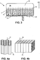
- the figure 3 shows a compartment structure 71, with vertical walls 7, that is to say oriented in the direction of gravity. It should be noted, however, that the walls may just as well be slightly or substantially inclined, as illustrated for example on the Figure 1 .
- the compartment structure is regular, i.e. a certain geometric pattern is repeated several times.
- the reservoir may have any shape, and in particular parallelepipedal or cylindrical.
- the compartment structure can be formed of stainless steel to give it good durability.
- the compartment structure may be formed of compatible plastic of the working fluid and in particular methanol; whereby it is compatible with this fluid commonly used for terrestrial applications, its life is satisfactory and its cost is low.
- said several distinct volumes communicate through passages of small section, preferably less than 1/10 of the largest section of the tank.
- the inner walls 7 have orifices 70 whose passage section is small, in order to create a hydraulic damping between the separate volumes of liquid.
- the passages between the separate volumes can also be located at the base of the compartments, without orifice on the height of the compartments.
- a grid 28 pierced with a plurality of small section holes allows the fluid to move between the compartments through a transfer chamber 29 located in the base zone 34 of the reservoir.
- This grid 28 also known as diffusion can advantageously serve as a support for the compartment structure 71.
- the height of the walls may be between 30% and 90% of the height of the tank, and will be chosen in particular so that the upper surface 19 of the liquid does not exceed the upper end of the walls 7.
- honeycomb structure of hexagonal mesh or a square mesh structure as illustrated respectively in FIGS. Figures 4a and 4b .
- Hexagonal compartments 77, (respectively square 78 ) communicate between their lower opening 76 (respectively 79 ).
- the plurality of walls may comprise walls oriented differently from each other.
- the size of the cells must not be too thin (less than one millimeter), otherwise the structure traps the liquid by capillarity and requires overfilling. to avoid drying the loop when starting in cold conditions or drops in power.
- the compartments are thus devoid of microporous structure, although the reservoir can form a macroporous structure.
- the compartment structure comprises a phase change material imparting a thermal inertia to said structure which contributes to limiting the sudden variations in temperature.
- the figure 5 is analogous to the figure 3 and shows a variant of the reservoir of the device with a liquid inlet at the bottom and on the side 35, which can simplify the inlet jet baffle 8.
- the inlet jet baffle 8 can then be reduced to a plate extending horizontally or at an extension pierced with a multitude of holes in the tube 5.
- the device may furthermore incidentally comprise a non-return member 6, arranged between the internal volume 30 of the reservoir and the microporous mass 10 of the evaporator, to prevent the liquid present in the evaporator from moving towards the volume inside the tank.
- This non-return member 6 makes it possible to prevent a liquid movement from the evaporator towards the reservoir when the boiling is triggered during the start-up phases of the system.
- this non-return member 6 may comprise a float (not shown in detail) whose density is slightly less than the fluid density in the liquid phase.
- the device may further comprise a power supply element 36, for example a heating element or pressurizing, located at the reservoir to control the pressurization of the loop during startup.
- a control system 'Ctrl' driver 38 in the case of a heating element, the supply of calories to this heating element 36, as a function of temperature information and / or pressure information delivered by sensors (not shown), in order to ensure the start of the two-phase loop.
- the heating element can be located both in the liquid phase and / or the vapor phase. Preferably, this element is located in the liquid phase and generates steam towards the upper part of the reservoir.
- the regulation with the heating element will be facilitated by the presence of a cold source in contact with the latter (ambient air, or other).
- this control system 'Ctrl' can also prepare the two-phase loop for an imminent and important arrival of calories on the evaporator, which makes it possible to anticipate the reaction of the two-phase loop with respect to the need for heat dissipation.
- the design of the loop can be optimized for large quantities of heat to be evacuated.
- the device is devoid of any mechanical pump although the invention does not exclude the presence of a mechanical booster pump.
Description
La présente invention est relative aux dispositifs de transport de chaleur à pompage capillaire, en particulier les dispositifs passifs à boucle fluide diphasique.The present invention relates to capillary pumping heat transport devices, in particular passive biphasic fluid loop devices.
Il est connu du document
Cependant, il est apparu que les phases de démarrage étaient particulièrement délicates pour des puissances thermiques importantes, il peut se produire un assèchement de la mèche capillaire et donc un échec du démarrage.However, it appeared that the starting phases were particularly delicate for large thermal powers, it can occur a drying of the capillary wick and thus a failure of startup.
De plus, si le dispositif est soumis à des accélérations, il peut se produire un phénomène de 'cold shock' dans le réservoir qui abaisse brutalement la pression et qui détériore la performance.In addition, if the device is subjected to accelerations, it can occur a phenomenon of cold shock in the tank which suddenly lowers the pressure and deteriorates the performance.
Il est donc apparu un besoin d'augmenter la fiabilité du démarrage et du fonctionnement de telles boucles.It has therefore appeared a need to increase the reliability of startup and operation of such loops.
A cet effet, l'invention a pour objet un dispositif de transfert thermique à pompage capillaire, adapté pour extraire de la chaleur depuis une source chaude et pour restituer cette chaleur à une source froide au moyen d'un fluide de travail diphasique contenu dans un circuit général clos, comprenant :
- au moins un évaporateur, ayant une entrée et une sortie, et une masse microporeuse adaptée pour assurer un pompage capillaire de fluide en phase liquide
- au moins un condenseur, ayant une entrée et une sortie,
- un réservoir ayant un volume intérieur et au moins un orifice d'entrée et/ou sortie, avec une portion de phase gazeuse située au-dessus d'une portion de phase liquide,
- un premier circuit de communication, pour du fluide essentiellement en phase vapeur, reliant la sortie de l'évaporateur à l'entrée du condenseur,
- un deuxième circuit de communication, pour du fluide essentiellement en phase liquide, reliant la sortie du condenseur au réservoir et à l'entrée de l'évaporateur, caractérisé en ce que le réservoir comprend plusieurs volumes distincts de phase liquide, les dits volumes distincts restant en communication fluide,
lesdits plusieurs volumes distincts communiquant par des passages de faible section, de manière à créer un amortissement hydraulique entre les volumes distincts de phase liquide.For this purpose, the subject of the invention is a capillary pumping thermal transfer device adapted to extract heat from a hot source and to restore this heat to a cold source by means of a two-phase working fluid contained in a enclosed general circuit, comprising:
- at least one evaporator, having an inlet and an outlet, and a microporous mass adapted to provide capillary pumping of fluid in the liquid phase
- at least one condenser, having an inlet and an outlet,
- a reservoir having an interior volume and at least one inlet and / or outlet orifice, with a portion of gaseous phase located above a portion of liquid phase,
- a first communication circuit, for substantially vapor phase fluid, connecting the evaporator outlet to the condenser inlet,
- a second communication circuit, for fluid essentially in the liquid phase, connecting the condenser outlet to the reservoir and to the inlet of the evaporator, characterized in that the reservoir comprises several distinct volumes of liquid phase, the said distinct volumes remaining in fluid communication,
said plurality of separate volumes communicating through passages of small section, so as to create a hydraulic damping between the separate volumes of liquid phase.
Grâce à ces dispositions, et à l'amortissement hydraulique ainsi créé, on évite des mouvements de fluide liquide trop importants dans le réservoir lorsque le dispositif est soumis à des accélérations, par exemple si celui-ci est à bord d'un véhicule de transport, et on évite ainsi un mélange dans le réservoir pouvant conduire à effet de 'cold shock', à savoir un abaissement brutal de la température de surface libre du liquide dans le réservoir qui entraine une baisse de la pression et une baisse de l'efficacité de la boucle. De même, la partition en plusieurs volumes distincts de liquide permet d'éviter un mélange qui pourrait intervenir du fait d'augmentations brusques de puissance thermique, en particulier le cas du démarrage.Thanks to these provisions, and the hydraulic damping thus created, it avoids excessive liquid fluid movements in the tank when the device is subjected to accelerations, for example if it is on board a transport vehicle , and thus avoids a mixture in the tank that can lead to the effect of 'cold shock', namely a sudden lowering of the free surface temperature of the liquid in the tank which causes a drop in pressure and a decrease in efficiency of the loop. Similarly, the partition in several separate volumes of liquid avoids a mixture that could occur due to sudden increases in thermal power, especially the case of startup.
Dans divers modes de réalisation de l'invention, on peut éventuellement avoir recours en outre à l'une et/ou à l'autre des dispositions suivantes :
- la phase liquide ne dépasse pas de l'extrémité supérieure des parois; ce qui évite le mélange de liquide en cas d'accélérations subies ;
- lesdits plusieurs volumes distincts communiquent par des passages de faible section de préférence inférieure au 1/10 de la plus grande section du réservoir ; moyennant quoi le déplacement d'un volume distinct à l'autre est possible mais limité en débit;
- la pluralité de parois internes forment une structure de compartiments régulière; moyennant quoi les parois se supportent les unes par rapport aux autres ;
- le réservoir comprend une structure macroporeuse et les compartiments sont dépourvus de structure microporeuse
- la structure de compartiment prend la forme d'une structure en nid d'abeille ; de sorte que la structure de compartiment présente un coût modéré car cette structure est optimisée ;
- le dispositif est principalement soumis à la gravité terrestre et la structure de compartiment comprend des cloisons inclinées ou verticales ; de sorte que les déplacements de fluides sont limités en cas d'accélération horizontale ;
- la structure de compartiment est formée en acier inox ; moyennant quoi sa durabilité est très satisfaisante ;
- la structure de compartiment est formée en plastique compatible avec le fluide de travail en particulier le méthanol ; moyennant quoi elle est compatible avec ce fluide communément utilisé, sa durée de vie est satisfaisante et son coût est faible ;
- lesdits plusieurs volumes distincts sont formés dans une structure maillée serrée (tissu métallique) ; moyennant quoi une alternative à la structure de parois est proposée ;
- la structure de compartiment comprend un matériau à changement de phase conférant une inertie thermique ; moyennant quoi l'effet de 'cold shock' est encore amoindri ;
- le réservoir comprend un déflecteur de jet d'entrée ; moyennant quoi l'effet de jet produit par l'entrée du liquide dans le réservoir est limité à une zone restreinte ;
- le réservoir peut être adjacent à l'évaporateur ou le réservoir peut être intégré à l'évaporateur ; moyennant quoi l'intégration mécanique du réservoir peut être améliorée ;
- le dispositif comprend en outre un organe anti retour agencé entre le volume intérieur du réservoir et la masse microporeuse de l'évaporateur, et agencée pour empêcher que du liquide présent dans l'évaporateur ne se déplace vers le volume intérieur du réservoir ;
- le dispositif est principalement soumis à la gravité, et l'organe anti retour comprend un flotteur;
- le dispositif de transfert thermique est préférentiellement dépourvu de pompe mécanique ; de sorte que sa fiabilité est augmentée ;
- le dispositif comprend en outre un élément d'apport d'énergie au niveau du réservoir pour contrôler la mise en pression de la boucle lors du démarrage ; de sorte que le démarrage de la boucle peut être fiabilisé.
- the liquid phase does not exceed the upper end of the walls; which avoids the mixing of liquid in case of accelerations undergone;
- said several different volumes communicate through passages of small section preferably less than 1/10 of the largest section of the tank; whereby the displacement of a separate volume to another is possible but limited in flow;
- the plurality of inner walls form a regular compartment structure; whereby the walls are supported with respect to each other;
- the reservoir comprises a macroporous structure and the compartments are devoid of microporous structure
- the compartment structure takes the form of a honeycomb structure; so that the compartment structure has a moderate cost because this structure is optimized;
- the device is mainly subjected to earth gravity and the compartment structure comprises inclined or vertical partitions; so that the movements of fluids are limited in case of horizontal acceleration;
- the compartment structure is formed of stainless steel; whereby its durability is very satisfactory;
- the compartment structure is formed of plastic compatible with the working fluid, in particular methanol; whereby it is compatible with this commonly used fluid, its life is satisfactory and its cost is low;
- said plurality of distinct volumes are formed in a tight mesh structure (metal fabric); whereby an alternative to the wall structure is proposed;
- the compartment structure comprises a phase change material imparting thermal inertia; whereby the effect of cold shock is further diminished;
- the reservoir comprises an inlet jet deflector; whereby the jet effect produced by the entry of the liquid into the reservoir is limited to a restricted area;
- the tank can be adjacent to the evaporator or the tank can be integrated with the evaporator; whereby the mechanical integration of the tank can be improved;
- the device further comprises an anti-return member arranged between the internal volume of the tank and the microporous mass of the evaporator, and arranged to prevent the liquid present in the evaporator from moving towards the interior volume of the tank;
- the device is mainly subjected to gravity, and the anti-return member comprises a float;
- the heat transfer device is preferably free of mechanical pump; so that its reliability is increased;
- the device further comprises an energy supply element at the reservoir to control the pressurization of the loop during startup; so that the start of the loop can be made reliable.
D'autres aspects, buts et avantages de l'invention apparaîtront à la lecture de la description suivante de plusieurs modes de réalisation de l'invention, donnés à titre d'exemples non limitatifs, en regard des dessins joints sur lesquels :
- la
figure 1 est une vue générale d'un dispositif selon un mode de réalisation de l'invention, - la
figure 2 est une variante du dispositif de laFigure 1 , - la
figure 3 montre de façon plus détaillée le réservoir du dispositif de lafigure 2 , - les
figures 4a et 4b montre des structures de compartiment dans le réservoir du dispositif desfigures 1 et 2 , - la
figure 5 est analogue à lafigure 3 et montre une variante du réservoir du dispositif de lafigure 2 . - la
figure 6 est une variante du dispositif de laFigure 1 .
- the
figure 1 is a general view of a device according to one embodiment of the invention, - the
figure 2 is a variant of the device of theFigure 1 , - the
figure 3 shows in more detail the reservoir of the device of thefigure 2 , - the
Figures 4a and 4b shows compartment structures in the tank of the deviceFigures 1 and 2 , - the
figure 5 is analogous to thefigure 3 and shows a variant of the reservoir of the device of thefigure 2 . - the
figure 6 is a variant of the device of theFigure 1 .
Sur les différentes figures, les mêmes références désignent des éléments identiques ou similaires.In the different figures, the same references designate identical or similar elements.
La
L'évaporateur 1 est thermiquement couplé à une source chaude 11, comme par exemple un ensemble comprenant des composants électroniques de puissance ou tout autre élément générant de la chaleur, par exemple par effet joule, ou par tout autre processus.The
Sous l'effet de l'apport de calories au contact 16 de la masse microporeuse emplie de liquide, du fluide passe de l'état liquide à l'état vapeur et s'évacue par la chambre de transfert 17 et par un premier circuit de communication 4 qui achemine ladite vapeur vers un condenseur 2 ayant une entrée 2a et une sortie 2b. Under the effect of the supply of calories to the contact 16 of the microporous mass filled with liquid, fluid passes from the liquid state to the vapor state and is evacuated by the
Dans l'évaporateur 1, les cavités libérées par la vapeur évacuée sont comblées par du liquide aspiré par la masse microporeuse 10 à partir de l'évidement central 15 susmentionné ; il s'agit du phénomène de pompage capillaire bien connu en soi.In the
A l'intérieur dudit condenseur 2, de la chaleur est cédé par le fluide en phase vapeur à une source froide 12, ce qui provoque un refroidissement du fluide vapeur et son changement de phase vers la phase liquide, autrement dit sa condensation.Inside said
Au niveau du condenseur 2, la température du fluide de travail 9 est abaissée en dessous de sa température d'équilibre liquide-vapeur, ce qui est aussi appelé sous-refroidissement ('sub cooling' en anglais) de sorte que le fluide ne peut pas repasser à l'état vapeur sans apport conséquent de chaleur.At the
La pression de vapeur pousse le liquide en direction de la sortie 2b du condenseur 2 qui débouche sur un deuxième circuit de communication 5, relié par ailleurs au réservoir 3.The vapor pressure pushes the liquid towards the
Le réservoir présente au moins un orifice d'entrée et/ou sortie 31, ici en l'occurrence sur la
C'est la température de cette surface de séparation 19 qui détermine la pression dans la boucle, cette pression correspond à la pression de saturation du fluide à la température prévalant à la surface de séparation 19.It is the temperature of this
Au niveau de la base du réservoir 34, la température du liquide est généralement inférieure à la température prévalant à la surface de séparation 19.At the base of the
Pour un fonctionnement correct de la boucle à pompage capillaire, il faut éviter que la température qui prévaut à la surface de séparation 19 évolue rapidement, et éviter en particulier un mélange de la phase liquide 9a qui a tendance à ramener du liquide froid du bas du réservoir vers le haut et donc de faire chuter la température de surface, et par la même la pression.For proper operation of the capillary pumping loop, it is necessary to prevent the temperature prevailing at the
Ce phénomène de chute brutale de température et de pression est appelé communément 'cold shock' et doit être évité.This phenomenon of sudden drop in temperature and pressure is commonly called cold shock and should be avoided.
Les premier et second circuits de communication fluide 4,5 sont de préférence des conduites tubulaires, mais il pourrait s'agir d'autres types de conduites ou de canaux de communication fluides (conduites rectangulaires, flexibles, etc.).The first and second
De même, le deuxième circuit de communication fluide 5 peut être sous la forme de deux conduites indépendantes distinctes 5a,5b (cf.
Ces configurations de conduites restent pertinentes lorsque plusieurs et/ou plusieurs condenseurs sont connectés en parallèle.These pipe configurations remain relevant when multiple and / or multiple condensers are connected in parallel.
Dans tous les cas, le deuxième circuit de communication fluide 5 relie la sortie du condenseur 2b à l'entrée de l'évaporateur 1a, soit indirectement en passant par le réservoir (cas de deux conduites indépendantes) soit directement (cas ou d'une seule conduite avec 'T').In all cases, the second
En vue d'éviter les phénomènes de mélange au sein du réservoir qui sont propices au phénomène de 'cold shock', il est prévu, à l'intérieur du réservoir plusieurs volumes de liquide distincts séparés les uns des autres mais lesdits volumes distincts restant en communication fluide. En particulier, et plus précisément, dans le réservoir peuvent être agencées une pluralité de parois internes 7 adaptées pour séparer lesdits plusieurs volumes distincts.In order to avoid mixing phenomena within the reservoir which are conducive to the phenomenon of 'cold shock', there are provided, inside the reservoir, several distinct volumes of liquid separated from each other but said distinct volumes remaining in fluid communication. In particular, and more specifically, in the reservoir can be arranged a plurality of
Toutefois, selon une alternative, lesdits plusieurs volumes distincts peuvent être formés dans une structure maillée serrée (non représentée sur les figures), comme par exemple une structure de type paille de fer, ou encore une structure de type éponge ou une structure macroporeuse, ou encore un empilage de sphères creuses percées de petits orifices.However, according to one alternative, said several distinct volumes may be formed in a tight mesh structure (not shown in the figures), such as for example an iron straw type structure, or a sponge-type structure or a macroporous structure, or still a stack of hollow spheres pierced with small orifices.
De plus, avantageusement selon l'invention, le réservoir comprend un déflecteur de jet d'entrée 8 au voisinage de l'orifice d'entrée 31a ou de l'orifice d'entrée/sortie 31 selon la configuration de la deuxième conduite.In addition, advantageously according to the invention, the reservoir comprises an
Ce déflecteur de jet d'entrée empêche qu'une arrivée rapide de liquide dans le réservoir ne crée un bouillonnement ou un courant favorisant le mélange du liquide. Il peut se présenter sous la forme d'un profilé en U orienté vers le bas, ou d'une cloche ou de toute autre forme créant une déviation suffisante de la trajectoire du jet d'entrée.This inlet jet deflector prevents a rapid arrival of liquid in the tank creates a bubbling or a current promoting the mixing of the liquid. It may be in the form of a downward U-shaped profile, or a bell or other shape creating a sufficient deflection of the path of the inlet jet.
La
Selon un aspect de la présente invention, lesdits plusieurs volumes distincts communiquent par des passages de section de faible, de préférence inférieure au 1/10 de la plus grande section du réservoir. Par exemple comme illustré sur la
Les passages entre les volumes distincts peuvent aussi se situer à la base des compartiments, sans orifice sur la hauteur des compartiments. Dans ce cas, une grille 28 percée d'une pluralité de trous de faible section permet au fluide de se déplacer entre les compartiments en passant par une chambre de transfert 29 située dans la zone de base 34 du réservoir. Cette grille 28 dite aussi de diffusion peut avantageusement servir de support pour la structure de compartiments 71.The passages between the separate volumes can also be located at the base of the compartments, without orifice on the height of the compartments. In this case, a
La hauteur des parois peut être comprise entre 30% et 90% de la hauteur du réservoir, et sera choisie en particulier pour que la surface supérieure 19 du liquide ne dépasse pas l'extrémité supérieure des parois 7.The height of the walls may be between 30% and 90% of the height of the tank, and will be chosen in particular so that the
De façon avantageuse, on peut choisir une structure en nid d'abeille de maille hexagonale ou un structure à maille carrée, comme illustré respectivement aux
De plus, la pluralité de parois peut comporter des parois orientées différemment les unes des autres. En particulier, il peut y avoir certaines parois parallèles au plan XZ, d'autres parallèles au plan XY et d'autres parallèles au plan YZ : ainsi on peut limiter les mouvements selon toutes les directions dans l'espace, ce qui est particulièrement avantageux si le dispositif est embarqué à bord d'un aéronef.In addition, the plurality of walls may comprise walls oriented differently from each other. In particular, there may be some walls parallel to the XZ plane, others parallel to the XY plane and others parallel to the YZ plane: thus one can limit the movements in all directions in space, which is particularly advantageous if the device is on board an aircraft.
Par ailleurs la taille des cellules ne doit pas être trop fine (inférieure au millimètre) sinon la structure piège le liquide par capillarité et demande un sur-remplissage pour éviter d'assécher la boucle lors des démarrages en conditions froides ou des baisses de puissances. Les compartiments sont ainsi dépourvus de structure microporeuse, bien que le réservoir puisse former une structure macroporeuse.In addition, the size of the cells must not be too thin (less than one millimeter), otherwise the structure traps the liquid by capillarity and requires overfilling. to avoid drying the loop when starting in cold conditions or drops in power. The compartments are thus devoid of microporous structure, although the reservoir can form a macroporous structure.
Selon un autre aspect avantageux de l'invention, la structure de compartiment comprend un matériau à changement de phase conférant une inertie thermique à ladite structure qui concourt à limiter les écarts brusques de température.According to another advantageous aspect of the invention, the compartment structure comprises a phase change material imparting a thermal inertia to said structure which contributes to limiting the sudden variations in temperature.
La
De plus, comme illustré à la
De façon préférentielle, cet organe anti-retour 6 peut comporter un flotteur (non représenté en détail) dont la densité est légèrement inférieure à la densité du fluide en phase liquide.Preferably, this
Par ailleurs, le dispositif peut comprendre en outre un élément d'apport d'énergie 36, par exemple un élément de chauffage ou de mise en pression, situé au niveau du réservoir pour contrôler la mise en pression de la boucle lors du démarrage. Un système de commande 'Ctrl' 38 pilote, dans le cas d'un élément de chauffage, l'apport de calories sur cet élément de chauffage 36, en fonction d'une information de température et/ou une information de pression délivrées par des capteurs (non représentés), et ceci afin d'assurer le démarrage de la boucle diphasique.Furthermore, the device may further comprise a
L'élément chauffant peut être situé aussi bien dans la phase liquide et/ou la phase vapeur. Préférentiellement cet élément est situé dans la phase liquide et génère de la vapeur vers la partie supérieure du réservoir. La régulation avec l'élément chauffant sera facilitée par la présence d'une source froide en contact de ce dernier (air ambiant, ou autre). De plus, ce système de commande 'Ctrl' peut aussi préparer la boucle diphasique à une arrivée imminente et importante de calories sur l'évaporateur, ce qui permet d'anticiper la réaction de la boucle diphasique par rapport au besoin de dissipation thermique. Le dimensionnement de la boucle peut être ainsi optimisé pour des quantités de chaleur importante à évacuer.The heating element can be located both in the liquid phase and / or the vapor phase. Preferably, this element is located in the liquid phase and generates steam towards the upper part of the reservoir. The regulation with the heating element will be facilitated by the presence of a cold source in contact with the latter (ambient air, or other). In addition, this control system 'Ctrl' can also prepare the two-phase loop for an imminent and important arrival of calories on the evaporator, which makes it possible to anticipate the reaction of the two-phase loop with respect to the need for heat dissipation. The design of the loop can be optimized for large quantities of heat to be evacuated.
Avantageusement selon l'invention, le dispositif est dépourvu d'une quelconque pompe mécanique bien que l'invention n'exclut pas la présence d'une pompe mécanique d'appoint.Advantageously according to the invention, the device is devoid of any mechanical pump although the invention does not exclude the presence of a mechanical booster pump.
Claims (14)
- Capillary-driven heat transfer device under the influence of gravity, adapted to extract heat from a heat source (11) and to release this heat to a cold source (12) by means of a two-phase working fluid contained in a closed general circuit, comprising:- at least one evaporator (1), having an inlet and an outlet, and a microporous mass (10) adapted to perform capillary pumping of fluid in the liquid phase- at least one condenser (2), having an inlet and an outlet,- a reservoir (3) having an inner chamber (30), and at least one inlet and/or outlet port (31;31a,31b), with a vapor phase portion located on top of a liquid phase portion,- a first communication circuit (4), for fluid mainly in the vapor phase, connecting the outlet of the evaporator to the inlet of the condenser,- a second communication circuit (5), for fluid mainly in the liquid phase, connecting the outlet of the condenser to the reservoir and to the inlet of the evaporator,characterized in that the reservoir (3) includes multiple separate volumes of the liquid phase, said separate volumes remaining in fluid communication, the reservoir including a plurality of inner partitions (7) forming compartments adapted to separate said multiple separate volumes of the liquid phase,
said multiple separate volumes communicating through small cross-sectional passages, in order to create hydraulic damping between the separate volumes of the liquid phase. - Device according to claim 1, wherein the liquid phase does not go over the upper edge of the partitions (7).
- Device according to one of claims 1 to 2, wherein the plurality of inner partitions form a regular compartment structure.
- Device according to one of claims 1 to 3, wherein the reservoir includes a macroporous structure and the compartments are deprived of a microporous structure.
- Device according to claim 4, mainly under the influence of the Earth's gravity, wherein the partitions form inclined or vertical separating walls.
- Device according to one of claims 4 to 5, wherein the compartment structure takes the form of a honeycomb structure.
- Device according to one of claims 4 to 6, wherein the compartment structure consists of a phase change material providing thermal inertia.
- Device according to one of claims 1 to 7, wherein the reservoir includes an input stream deflector (8) near the inlet port.
- Device according to one of claims 1 to 8, wherein the reservoir can be located next to the evaporator, or the reservoir can be integrated into the evaporator.
- Device according to one of claims 1 to 9, including a non-return device (6) arranged between the inner chamber (30) of the reservoir and the microporous mass (10) of the evaporator, and arranged to prevent the liquid present in the evaporator from moving into the inner chamber of the reservoir.
- Device according to claim 10, mainly under the influence of the Earth's gravity, wherein the non-return device includes a float (60).
- A heat transfer device according to one of the preceding claims, characterized in that it is deprived of a mechanical pump.
- A device according to one of the preceding claims, additionally including an energy-providing element at the reservoir to control the pressurisation of the loop during startup.
- A device according to one of the preceding claims, wherein the cross-section of the small cross-sectional passages is preferably less than 1/10 of the largest cross-section of the reservoir.
Applications Claiming Priority (2)
| Application Number | Priority Date | Filing Date | Title |
|---|---|---|---|
| FR1158202A FR2979981B1 (en) | 2011-09-14 | 2011-09-14 | CAPILLARY PUMP HEAT DELIVERY DEVICE |
| PCT/EP2012/067752 WO2013037784A1 (en) | 2011-09-14 | 2012-09-12 | Capillary-pumping heat-transport device |
Publications (2)
| Publication Number | Publication Date |
|---|---|
| EP2756251A1 EP2756251A1 (en) | 2014-07-23 |
| EP2756251B1 true EP2756251B1 (en) | 2016-04-06 |
Family
ID=46829776
Family Applications (1)
| Application Number | Title | Priority Date | Filing Date |
|---|---|---|---|
| EP12756742.8A Active EP2756251B1 (en) | 2011-09-14 | 2012-09-12 | Capillary-pumping heat-transport device |
Country Status (7)
| Country | Link |
|---|---|
| US (1) | US9958214B2 (en) |
| EP (1) | EP2756251B1 (en) |
| JP (1) | JP6163490B2 (en) |
| CN (1) | CN104094074B (en) |
| ES (1) | ES2580402T3 (en) |
| FR (1) | FR2979981B1 (en) |
| WO (1) | WO2013037784A1 (en) |
Cited By (1)
| Publication number | Priority date | Publication date | Assignee | Title |
|---|---|---|---|---|
| RU2665754C1 (en) * | 2017-06-22 | 2018-09-04 | Александр Михайлович Деревягин | Method and device for heat transfer |
Families Citing this family (6)
| Publication number | Priority date | Publication date | Assignee | Title |
|---|---|---|---|---|
| US9664378B2 (en) * | 2013-04-17 | 2017-05-30 | Venkata Sundereswar Rao VEMPATI | Energy efficient pressure less steam generator |
| FR3006431B1 (en) * | 2013-05-29 | 2015-06-05 | Euro Heat Pipes | DEVICE FOR TRANSPORTING HEAT WITH A DIPHASIC FLUID |
| FR3009377B1 (en) * | 2013-08-01 | 2018-10-19 | Euro Heat Pipes | EVAPORATOR WITH ANTI-RETURN DEVICE FOR DIPHASIC LOOP |
| CN103987235B (en) * | 2014-04-14 | 2017-02-08 | 中国电子科技集团公司第十一研究所 | Heat dissipation method and system |
| DE102015107473A1 (en) | 2015-05-12 | 2016-11-17 | Benteler Automobiltechnik Gmbh | Automotive heat exchanger system |
| CN109029034A (en) * | 2018-07-12 | 2018-12-18 | 南京航空航天大学 | A kind of driving heat pipe circulation heat exchanger certainly |
Family Cites Families (57)
| Publication number | Priority date | Publication date | Assignee | Title |
|---|---|---|---|---|
| US2366955A (en) | 1941-09-20 | 1945-01-09 | Servel Inc | Refrigeration |
| US3613778A (en) * | 1969-03-03 | 1971-10-19 | Northrop Corp | Flat plate heat pipe with structural wicks |
| DE2235792A1 (en) * | 1972-07-21 | 1974-01-31 | Dornier System Gmbh | DEVICE FOR TRANSFER OF THERMAL ENERGY |
| US4061131A (en) * | 1975-11-24 | 1977-12-06 | Acme Engineering And Manufacturing Corporation | Heat transfer system particularly applicable to solar heating installations |
| US4286579A (en) | 1979-05-30 | 1981-09-01 | Barry Johnston | Closed loop solar collector system |
| US4296729A (en) * | 1980-02-04 | 1981-10-27 | Suntime, Inc. | Solar hot water heating system |
| JPH0230439B2 (en) | 1985-01-30 | 1990-07-06 | Matsushita Electric Ind Co Ltd | RUUPUSHIKIHIITOPAIPU |
| FR2578638B1 (en) * | 1985-03-08 | 1989-08-18 | Inst Francais Du Petrole | METHOD FOR TRANSFERRING HEAT FROM A HOT FLUID TO A COLD FLUID USING A MIXED FLUID AS A HEAT EXCHANGER |
| JPS62233686A (en) * | 1986-03-31 | 1987-10-14 | Yamato Seisakusho:Kk | Heat transfer device |
| JPH0718408B2 (en) | 1986-06-23 | 1995-03-06 | 謙治 岡安 | Heat driven pump |
| FR2602851B1 (en) | 1986-08-05 | 1988-11-18 | Nantes D Avignonet Philippe De | ANTI-RETURN SYSTEM FOR ALL NON-PULSED OR ASPIRATED FLOW PIPES |
| US4830097A (en) * | 1987-07-15 | 1989-05-16 | The United States Of America As Represented By The Administrator Of The National Aeronautics And Space Administration | Space vehicle thermal rejection system |
| JP2657809B2 (en) | 1987-12-22 | 1997-09-30 | 謙治 岡安 | Heat transfer device |
| JP2544433B2 (en) * | 1988-03-31 | 1996-10-16 | 三機工業株式会社 | Refrigerant natural circulation heat transfer device |
| US4957157A (en) * | 1989-04-13 | 1990-09-18 | General Electric Co. | Two-phase thermal control system with a spherical wicked reservoir |
| JP2859927B2 (en) | 1990-05-16 | 1999-02-24 | 株式会社東芝 | Cooling device and temperature control device |
| JPH0490498A (en) * | 1990-08-03 | 1992-03-24 | Mitsubishi Electric Corp | Heat transfer device |
| JP2801998B2 (en) * | 1992-10-12 | 1998-09-21 | 富士通株式会社 | Electronic equipment cooling device |
| US5816313A (en) * | 1994-02-25 | 1998-10-06 | Lockheed Martin Corporation | Pump, and earth-testable spacecraft capillary heat transport loop using augmentation pump and check valves |
| BE1009410A3 (en) * | 1995-06-14 | 1997-03-04 | B C A Sa | Device heat transport. |
| FR2752291B1 (en) * | 1996-08-12 | 1998-09-25 | Centre Nat Etd Spatiales | HAIR EVAPORATOR FOR DIPHASIC LOOP OF TRANSFER OF ENERGY BETWEEN A HOT SOURCE AND A COLD SOURCE |
| JP3748984B2 (en) | 1997-05-29 | 2006-02-22 | 本田技研工業株式会社 | Thermally driven hydraulic pressure generator |
| JP2000241089A (en) * | 1999-02-19 | 2000-09-08 | Mitsubishi Electric Corp | Evaporator, heat sink, and system and method for transporting heat |
| US6227288B1 (en) * | 2000-05-01 | 2001-05-08 | The United States Of America As Represented By The Secretary Of The Air Force | Multifunctional capillary system for loop heat pipe statement of government interest |
| US7549461B2 (en) | 2000-06-30 | 2009-06-23 | Alliant Techsystems Inc. | Thermal management system |
| US8109325B2 (en) | 2000-06-30 | 2012-02-07 | Alliant Techsystems Inc. | Heat transfer system |
| US8047268B1 (en) | 2002-10-02 | 2011-11-01 | Alliant Techsystems Inc. | Two-phase heat transfer system and evaporators and condensers for use in heat transfer systems |
| US8136580B2 (en) | 2000-06-30 | 2012-03-20 | Alliant Techsystems Inc. | Evaporator for a heat transfer system |
| US6883588B1 (en) * | 2000-07-24 | 2005-04-26 | Space Systems/Loral, Inc. | Spacecraft radiator system using a heat pump |
| US6976527B2 (en) * | 2001-07-17 | 2005-12-20 | The Regents Of The University Of California | MEMS microcapillary pumped loop for chip-level temperature control |
| JP3661862B2 (en) * | 2002-02-05 | 2005-06-22 | 独立行政法人 宇宙航空研究開発機構 | accumulator |
| US7061446B1 (en) * | 2002-10-24 | 2006-06-13 | Raytheon Company | Method and apparatus for controlling temperature gradients within a structure being cooled |
| FR2851503B1 (en) * | 2003-02-20 | 2008-02-15 | VENTILATION, HEATING AND / OR AIR CONDITIONING APPARATUS FOR A MOTOR VEHICLE WITH SIMULTANEOUS AIR COOLING AND A HEAT PUMP FLUID | |
| US7823629B2 (en) * | 2003-03-20 | 2010-11-02 | Thermal Corp. | Capillary assisted loop thermosiphon apparatus |
| US6865897B2 (en) * | 2003-07-10 | 2005-03-15 | Praxair Technology, Inc. | Method for providing refrigeration using capillary pumped liquid |
| US20050067146A1 (en) | 2003-09-02 | 2005-03-31 | Thayer John Gilbert | Two phase cooling system method for burn-in testing |
| JP2006064193A (en) * | 2004-08-24 | 2006-03-09 | Mitsubishi Electric Corp | Loop heat exchange heat transporting device |
| US20060065386A1 (en) | 2004-08-31 | 2006-03-30 | Mohammed Alam | Self-actuating and regulating heat exchange system |
| US6990816B1 (en) * | 2004-12-22 | 2006-01-31 | Advanced Cooling Technologies, Inc. | Hybrid capillary cooling apparatus |
| JP4381998B2 (en) | 2005-02-24 | 2009-12-09 | 株式会社日立製作所 | Liquid cooling system |
| CN2861836Y (en) * | 2005-09-21 | 2007-01-24 | 上海海事大学 | Compound heat pipe moisture separator |
| TWM284951U (en) * | 2005-09-21 | 2006-01-01 | Yen Sun Technology Corp | Heat dissipating device for an electronic device |
| TWI276396B (en) * | 2006-01-13 | 2007-03-11 | Ind Tech Res Inst | Closed-loop latent heat cooling method, and capillary force or non-nozzle module thereof |
| US7748436B1 (en) * | 2006-05-03 | 2010-07-06 | Advanced Cooling Technologies, Inc | Evaporator for capillary loop |
| WO2007146083A2 (en) | 2006-06-06 | 2007-12-21 | Albert Montague | Backflow preventer valve |
| US20080078530A1 (en) * | 2006-10-02 | 2008-04-03 | Foxconn Technology Co., Ltd. | Loop heat pipe with flexible artery mesh |
| US20080225489A1 (en) * | 2006-10-23 | 2008-09-18 | Teledyne Licensing, Llc | Heat spreader with high heat flux and high thermal conductivity |
| TWI318679B (en) * | 2007-05-16 | 2009-12-21 | Ind Tech Res Inst | Heat dissipation system with an plate evaporator |
| CN100460798C (en) * | 2007-05-16 | 2009-02-11 | 中山大学 | Temperature-evenness loop heat pipe device |
| FR2919923B1 (en) | 2007-08-08 | 2009-10-30 | Astrium Sas Soc Par Actions Si | PASSIVE DEVICE WITH MICRO BUCKLE FLUID WITH CAPILLARY PUMPING |
| JP2010539701A (en) * | 2007-09-17 | 2010-12-16 | アナトリエヴィチ ポミトキン,ワディム | Heat spreader for heat pipe cooler and water cooler |
| US8196395B2 (en) | 2009-06-29 | 2012-06-12 | Lightsail Energy, Inc. | Compressed air energy storage system utilizing two-phase flow to facilitate heat exchange |
| FR2949642B1 (en) | 2009-08-27 | 2012-05-04 | Alstom Transport Sa | ELECTRIC POWER CONVERTER FOR A RAILWAY VEHICLE |
| JP5287638B2 (en) * | 2009-09-25 | 2013-09-11 | 富士通株式会社 | Loop heat pipe and electronic equipment |
| JP5556897B2 (en) * | 2010-11-01 | 2014-07-23 | 富士通株式会社 | Loop heat pipe and electronic device using the same |
| CN102723316A (en) * | 2011-03-29 | 2012-10-10 | 北京奇宏科技研发中心有限公司 | Loop heat pipe structure |
| FR2979982B1 (en) * | 2011-09-14 | 2016-09-09 | Euro Heat Pipes | CAPILLARY PUMP HEAT DELIVERY DEVICE |
-
2011
- 2011-09-14 FR FR1158202A patent/FR2979981B1/en not_active Expired - Fee Related
-
2012
- 2012-09-12 US US14/344,880 patent/US9958214B2/en not_active Expired - Fee Related
- 2012-09-12 EP EP12756742.8A patent/EP2756251B1/en active Active
- 2012-09-12 CN CN201280055587.5A patent/CN104094074B/en active Active
- 2012-09-12 ES ES12756742.8T patent/ES2580402T3/en active Active
- 2012-09-12 WO PCT/EP2012/067752 patent/WO2013037784A1/en active Application Filing
- 2012-09-12 JP JP2014530188A patent/JP6163490B2/en not_active Expired - Fee Related
Cited By (1)
| Publication number | Priority date | Publication date | Assignee | Title |
|---|---|---|---|---|
| RU2665754C1 (en) * | 2017-06-22 | 2018-09-04 | Александр Михайлович Деревягин | Method and device for heat transfer |
Also Published As
| Publication number | Publication date |
|---|---|
| US9958214B2 (en) | 2018-05-01 |
| US20150083373A1 (en) | 2015-03-26 |
| JP6163490B2 (en) | 2017-07-12 |
| ES2580402T3 (en) | 2016-08-23 |
| FR2979981A1 (en) | 2013-03-15 |
| EP2756251A1 (en) | 2014-07-23 |
| CN104094074B (en) | 2016-08-24 |
| FR2979981B1 (en) | 2016-09-09 |
| CN104094074A (en) | 2014-10-08 |
| JP2014527153A (en) | 2014-10-09 |
| WO2013037784A1 (en) | 2013-03-21 |
Similar Documents
| Publication | Publication Date | Title |
|---|---|---|
| EP2756251B1 (en) | Capillary-pumping heat-transport device | |
| EP2756252B1 (en) | Heat transfer device using capillary pumping | |
| EP2956729B1 (en) | Heat transport device with diphasic fluid | |
| EP3004773A1 (en) | Heat transfer device with diphasic fluid | |
| EP3207324B1 (en) | Flat heat pipe with reservoir function | |
| WO1997000416A1 (en) | Capillary pumped heat transfer loop | |
| EP0782885A1 (en) | High efficiency spray device particularly for producing water microdroplets | |
| FR3045793A1 (en) | BATTERY PACK COOLED BY CONSTANT PRESSURE PHASE CHANGE MATERIAL | |
| EP2851949A1 (en) | Cooling device for integrated circuit chip | |
| EP0314585B1 (en) | Gas-liquid heat-exchanger with condensation | |
| FR3016923A3 (en) | DEGASSING JAR AND COOLING SYSTEM FOR A MOTOR VEHICLE COMPRISING SUCH A DEGASSING JAR | |
| FR2524124A1 (en) | CALORIFIC STORAGE AND RETURN PROCESS, AND DEVICE FOR IMPLEMENTING IT, CONSTITUTING A BUILDING ELEMENT | |
| EP2393714A1 (en) | Cryogenic tank and space launcher including such a tank | |
| EP2476301B1 (en) | System for thermally controlling an apparatus | |
| CA2560670A1 (en) | Refrigerating plate for a refrigerator or freezer | |
| EP0022391B1 (en) | Acceleration-proof cryostatic device | |
| EP3027995B1 (en) | Evaporator with non-return device for diphasic loop | |
| FR3032027A1 (en) | DIPHASIC COOLING BUCKLE WITH SATELLITE EVAPORATORS | |
| FR2706531A1 (en) | Expansion tank (vessel) for a heat engine cooling circuit | |
| FR2978819A1 (en) | Desorber for absorption air conditioning device for air conditioning of car, has distribution system for distributing mixture of absorbent and refrigerating fluids, where distribution system is built into wall of housing | |
| WO2019220035A1 (en) | Evaporator for a fluid circuit and fluid circuit comprising such an evaporator | |
| WO2013017439A1 (en) | Desorber for an air conditioning device | |
| BE345688A (en) |
Legal Events
| Date | Code | Title | Description |
|---|---|---|---|
| PUAI | Public reference made under article 153(3) epc to a published international application that has entered the european phase |
Free format text: ORIGINAL CODE: 0009012 |
|
| 17P | Request for examination filed |
Effective date: 20140311 |
|
| AK | Designated contracting states |
Kind code of ref document: A1 Designated state(s): AL AT BE BG CH CY CZ DE DK EE ES FI FR GB GR HR HU IE IS IT LI LT LU LV MC MK MT NL NO PL PT RO RS SE SI SK SM TR |
|
| DAX | Request for extension of the european patent (deleted) | ||
| GRAP | Despatch of communication of intention to grant a patent |
Free format text: ORIGINAL CODE: EPIDOSNIGR1 |
|
| INTG | Intention to grant announced |
Effective date: 20151006 |
|
| GRAS | Grant fee paid |
Free format text: ORIGINAL CODE: EPIDOSNIGR3 |
|
| GRAA | (expected) grant |
Free format text: ORIGINAL CODE: 0009210 |
|
| AK | Designated contracting states |
Kind code of ref document: B1 Designated state(s): AL AT BE BG CH CY CZ DE DK EE ES FI FR GB GR HR HU IE IS IT LI LT LU LV MC MK MT NL NO PL PT RO RS SE SI SK SM TR |
|
| REG | Reference to a national code |
Ref country code: GB Ref legal event code: FG4D Free format text: NOT ENGLISH |
|
| REG | Reference to a national code |
Ref country code: AT Ref legal event code: REF Ref document number: 788285 Country of ref document: AT Kind code of ref document: T Effective date: 20160415 Ref country code: CH Ref legal event code: EP |
|
| REG | Reference to a national code |
Ref country code: IE Ref legal event code: FG4D Free format text: LANGUAGE OF EP DOCUMENT: FRENCH |
|
| REG | Reference to a national code |
Ref country code: DE Ref legal event code: R096 Ref document number: 602012016689 Country of ref document: DE |
|
| REG | Reference to a national code |
Ref country code: NL Ref legal event code: FP |
|
| REG | Reference to a national code |
Ref country code: FR Ref legal event code: PLFP Year of fee payment: 5 |
|
| REG | Reference to a national code |
Ref country code: SE Ref legal event code: TRGR |
|
| REG | Reference to a national code |
Ref country code: LT Ref legal event code: MG4D |
|
| REG | Reference to a national code |
Ref country code: AT Ref legal event code: MK05 Ref document number: 788285 Country of ref document: AT Kind code of ref document: T Effective date: 20160406 |
|
| REG | Reference to a national code |
Ref country code: ES Ref legal event code: FG2A Ref document number: 2580402 Country of ref document: ES Kind code of ref document: T3 Effective date: 20160823 |
|
| PG25 | Lapsed in a contracting state [announced via postgrant information from national office to epo] |
Ref country code: NO Free format text: LAPSE BECAUSE OF FAILURE TO SUBMIT A TRANSLATION OF THE DESCRIPTION OR TO PAY THE FEE WITHIN THE PRESCRIBED TIME-LIMIT Effective date: 20160706 Ref country code: LT Free format text: LAPSE BECAUSE OF FAILURE TO SUBMIT A TRANSLATION OF THE DESCRIPTION OR TO PAY THE FEE WITHIN THE PRESCRIBED TIME-LIMIT Effective date: 20160406 Ref country code: IS Free format text: LAPSE BECAUSE OF FAILURE TO SUBMIT A TRANSLATION OF THE DESCRIPTION OR TO PAY THE FEE WITHIN THE PRESCRIBED TIME-LIMIT Effective date: 20160806 Ref country code: PL Free format text: LAPSE BECAUSE OF FAILURE TO SUBMIT A TRANSLATION OF THE DESCRIPTION OR TO PAY THE FEE WITHIN THE PRESCRIBED TIME-LIMIT Effective date: 20160406 Ref country code: FI Free format text: LAPSE BECAUSE OF FAILURE TO SUBMIT A TRANSLATION OF THE DESCRIPTION OR TO PAY THE FEE WITHIN THE PRESCRIBED TIME-LIMIT Effective date: 20160406 |
|
| PG25 | Lapsed in a contracting state [announced via postgrant information from national office to epo] |
Ref country code: LV Free format text: LAPSE BECAUSE OF FAILURE TO SUBMIT A TRANSLATION OF THE DESCRIPTION OR TO PAY THE FEE WITHIN THE PRESCRIBED TIME-LIMIT Effective date: 20160406 Ref country code: PT Free format text: LAPSE BECAUSE OF FAILURE TO SUBMIT A TRANSLATION OF THE DESCRIPTION OR TO PAY THE FEE WITHIN THE PRESCRIBED TIME-LIMIT Effective date: 20160808 Ref country code: HR Free format text: LAPSE BECAUSE OF FAILURE TO SUBMIT A TRANSLATION OF THE DESCRIPTION OR TO PAY THE FEE WITHIN THE PRESCRIBED TIME-LIMIT Effective date: 20160406 Ref country code: GR Free format text: LAPSE BECAUSE OF FAILURE TO SUBMIT A TRANSLATION OF THE DESCRIPTION OR TO PAY THE FEE WITHIN THE PRESCRIBED TIME-LIMIT Effective date: 20160707 Ref country code: AT Free format text: LAPSE BECAUSE OF FAILURE TO SUBMIT A TRANSLATION OF THE DESCRIPTION OR TO PAY THE FEE WITHIN THE PRESCRIBED TIME-LIMIT Effective date: 20160406 Ref country code: RS Free format text: LAPSE BECAUSE OF FAILURE TO SUBMIT A TRANSLATION OF THE DESCRIPTION OR TO PAY THE FEE WITHIN THE PRESCRIBED TIME-LIMIT Effective date: 20160406 |
|
| REG | Reference to a national code |
Ref country code: DE Ref legal event code: R097 Ref document number: 602012016689 Country of ref document: DE |
|
| PG25 | Lapsed in a contracting state [announced via postgrant information from national office to epo] |
Ref country code: DK Free format text: LAPSE BECAUSE OF FAILURE TO SUBMIT A TRANSLATION OF THE DESCRIPTION OR TO PAY THE FEE WITHIN THE PRESCRIBED TIME-LIMIT Effective date: 20160406 Ref country code: RO Free format text: LAPSE BECAUSE OF FAILURE TO SUBMIT A TRANSLATION OF THE DESCRIPTION OR TO PAY THE FEE WITHIN THE PRESCRIBED TIME-LIMIT Effective date: 20160406 Ref country code: SK Free format text: LAPSE BECAUSE OF FAILURE TO SUBMIT A TRANSLATION OF THE DESCRIPTION OR TO PAY THE FEE WITHIN THE PRESCRIBED TIME-LIMIT Effective date: 20160406 Ref country code: CZ Free format text: LAPSE BECAUSE OF FAILURE TO SUBMIT A TRANSLATION OF THE DESCRIPTION OR TO PAY THE FEE WITHIN THE PRESCRIBED TIME-LIMIT Effective date: 20160406 Ref country code: EE Free format text: LAPSE BECAUSE OF FAILURE TO SUBMIT A TRANSLATION OF THE DESCRIPTION OR TO PAY THE FEE WITHIN THE PRESCRIBED TIME-LIMIT Effective date: 20160406 |
|
| PLBE | No opposition filed within time limit |
Free format text: ORIGINAL CODE: 0009261 |
|
| STAA | Information on the status of an ep patent application or granted ep patent |
Free format text: STATUS: NO OPPOSITION FILED WITHIN TIME LIMIT |
|
| PG25 | Lapsed in a contracting state [announced via postgrant information from national office to epo] |
Ref country code: SM Free format text: LAPSE BECAUSE OF FAILURE TO SUBMIT A TRANSLATION OF THE DESCRIPTION OR TO PAY THE FEE WITHIN THE PRESCRIBED TIME-LIMIT Effective date: 20160406 |
|
| 26N | No opposition filed |
Effective date: 20170110 |
|
| PG25 | Lapsed in a contracting state [announced via postgrant information from national office to epo] |
Ref country code: MC Free format text: LAPSE BECAUSE OF FAILURE TO SUBMIT A TRANSLATION OF THE DESCRIPTION OR TO PAY THE FEE WITHIN THE PRESCRIBED TIME-LIMIT Effective date: 20160406 |
|
| REG | Reference to a national code |
Ref country code: CH Ref legal event code: PL |
|
| PG25 | Lapsed in a contracting state [announced via postgrant information from national office to epo] |
Ref country code: SI Free format text: LAPSE BECAUSE OF FAILURE TO SUBMIT A TRANSLATION OF THE DESCRIPTION OR TO PAY THE FEE WITHIN THE PRESCRIBED TIME-LIMIT Effective date: 20160406 |
|
| REG | Reference to a national code |
Ref country code: IE Ref legal event code: MM4A |
|
| PG25 | Lapsed in a contracting state [announced via postgrant information from national office to epo] |
Ref country code: CH Free format text: LAPSE BECAUSE OF NON-PAYMENT OF DUE FEES Effective date: 20160930 Ref country code: IE Free format text: LAPSE BECAUSE OF NON-PAYMENT OF DUE FEES Effective date: 20160912 Ref country code: LI Free format text: LAPSE BECAUSE OF NON-PAYMENT OF DUE FEES Effective date: 20160930 |
|
| REG | Reference to a national code |
Ref country code: FR Ref legal event code: PLFP Year of fee payment: 6 |
|
| PG25 | Lapsed in a contracting state [announced via postgrant information from national office to epo] |
Ref country code: LU Free format text: LAPSE BECAUSE OF NON-PAYMENT OF DUE FEES Effective date: 20160912 |
|
| PG25 | Lapsed in a contracting state [announced via postgrant information from national office to epo] |
Ref country code: HU Free format text: LAPSE BECAUSE OF FAILURE TO SUBMIT A TRANSLATION OF THE DESCRIPTION OR TO PAY THE FEE WITHIN THE PRESCRIBED TIME-LIMIT; INVALID AB INITIO Effective date: 20120912 |
|
| PG25 | Lapsed in a contracting state [announced via postgrant information from national office to epo] |
Ref country code: MT Free format text: LAPSE BECAUSE OF FAILURE TO SUBMIT A TRANSLATION OF THE DESCRIPTION OR TO PAY THE FEE WITHIN THE PRESCRIBED TIME-LIMIT Effective date: 20160406 Ref country code: MK Free format text: LAPSE BECAUSE OF FAILURE TO SUBMIT A TRANSLATION OF THE DESCRIPTION OR TO PAY THE FEE WITHIN THE PRESCRIBED TIME-LIMIT Effective date: 20160406 Ref country code: CY Free format text: LAPSE BECAUSE OF FAILURE TO SUBMIT A TRANSLATION OF THE DESCRIPTION OR TO PAY THE FEE WITHIN THE PRESCRIBED TIME-LIMIT Effective date: 20160406 |
|
| PG25 | Lapsed in a contracting state [announced via postgrant information from national office to epo] |
Ref country code: BG Free format text: LAPSE BECAUSE OF FAILURE TO SUBMIT A TRANSLATION OF THE DESCRIPTION OR TO PAY THE FEE WITHIN THE PRESCRIBED TIME-LIMIT Effective date: 20160406 |
|
| REG | Reference to a national code |
Ref country code: FR Ref legal event code: PLFP Year of fee payment: 7 |
|
| PG25 | Lapsed in a contracting state [announced via postgrant information from national office to epo] |
Ref country code: AL Free format text: LAPSE BECAUSE OF FAILURE TO SUBMIT A TRANSLATION OF THE DESCRIPTION OR TO PAY THE FEE WITHIN THE PRESCRIBED TIME-LIMIT Effective date: 20160406 Ref country code: TR Free format text: LAPSE BECAUSE OF FAILURE TO SUBMIT A TRANSLATION OF THE DESCRIPTION OR TO PAY THE FEE WITHIN THE PRESCRIBED TIME-LIMIT Effective date: 20160406 |
|
| PGFP | Annual fee paid to national office [announced via postgrant information from national office to epo] |
Ref country code: IT Payment date: 20210910 Year of fee payment: 10 |
|
| PGFP | Annual fee paid to national office [announced via postgrant information from national office to epo] |
Ref country code: GB Payment date: 20210928 Year of fee payment: 10 Ref country code: DE Payment date: 20210908 Year of fee payment: 10 Ref country code: SE Payment date: 20210916 Year of fee payment: 10 Ref country code: BE Payment date: 20210927 Year of fee payment: 10 |
|
| PGFP | Annual fee paid to national office [announced via postgrant information from national office to epo] |
Ref country code: ES Payment date: 20211005 Year of fee payment: 10 |
|
| PGFP | Annual fee paid to national office [announced via postgrant information from national office to epo] |
Ref country code: NL Payment date: 20220823 Year of fee payment: 11 |
|
| REG | Reference to a national code |
Ref country code: DE Ref legal event code: R119 Ref document number: 602012016689 Country of ref document: DE |
|
| REG | Reference to a national code |
Ref country code: SE Ref legal event code: EUG |
|
| GBPC | Gb: european patent ceased through non-payment of renewal fee |
Effective date: 20220912 |
|
| REG | Reference to a national code |
Ref country code: BE Ref legal event code: MM Effective date: 20220930 |
|
| PG25 | Lapsed in a contracting state [announced via postgrant information from national office to epo] |
Ref country code: DE Free format text: LAPSE BECAUSE OF NON-PAYMENT OF DUE FEES Effective date: 20230401 |
|
| PG25 | Lapsed in a contracting state [announced via postgrant information from national office to epo] |
Ref country code: SE Free format text: LAPSE BECAUSE OF NON-PAYMENT OF DUE FEES Effective date: 20220913 |
|
| PG25 | Lapsed in a contracting state [announced via postgrant information from national office to epo] |
Ref country code: BE Free format text: LAPSE BECAUSE OF NON-PAYMENT OF DUE FEES Effective date: 20220930 |
|
| REG | Reference to a national code |
Ref country code: ES Ref legal event code: FD2A Effective date: 20231027 |
|
| PG25 | Lapsed in a contracting state [announced via postgrant information from national office to epo] |
Ref country code: IT Free format text: LAPSE BECAUSE OF NON-PAYMENT OF DUE FEES Effective date: 20220912 Ref country code: GB Free format text: LAPSE BECAUSE OF NON-PAYMENT OF DUE FEES Effective date: 20220912 |
|
| PGFP | Annual fee paid to national office [announced via postgrant information from national office to epo] |
Ref country code: FR Payment date: 20230821 Year of fee payment: 12 |
|
| PG25 | Lapsed in a contracting state [announced via postgrant information from national office to epo] |
Ref country code: ES Free format text: LAPSE BECAUSE OF NON-PAYMENT OF DUE FEES Effective date: 20220913 |
|
| PG25 | Lapsed in a contracting state [announced via postgrant information from national office to epo] |
Ref country code: ES Free format text: LAPSE BECAUSE OF NON-PAYMENT OF DUE FEES Effective date: 20220913 |