EP2755286A1 - Rails conducteurs de montage - Google Patents
Rails conducteurs de montage Download PDFInfo
- Publication number
- EP2755286A1 EP2755286A1 EP13000110.0A EP13000110A EP2755286A1 EP 2755286 A1 EP2755286 A1 EP 2755286A1 EP 13000110 A EP13000110 A EP 13000110A EP 2755286 A1 EP2755286 A1 EP 2755286A1
- Authority
- EP
- European Patent Office
- Prior art keywords
- built
- busbar
- hollow profile
- chambers
- busbar according
- Prior art date
- Legal status (The legal status is an assumption and is not a legal conclusion. Google has not performed a legal analysis and makes no representation as to the accuracy of the status listed.)
- Withdrawn
Links
Images


Classifications
-
- H—ELECTRICITY
- H01—ELECTRIC ELEMENTS
- H01R—ELECTRICALLY-CONDUCTIVE CONNECTIONS; STRUCTURAL ASSOCIATIONS OF A PLURALITY OF MUTUALLY-INSULATED ELECTRICAL CONNECTING ELEMENTS; COUPLING DEVICES; CURRENT COLLECTORS
- H01R25/00—Coupling parts adapted for simultaneous co-operation with two or more identical counterparts, e.g. for distributing energy to two or more circuits
- H01R25/14—Rails or bus-bars constructed so that the counterparts can be connected thereto at any point along their length
- H01R25/145—Details, e.g. end pieces or joints
-
- F—MECHANICAL ENGINEERING; LIGHTING; HEATING; WEAPONS; BLASTING
- F21—LIGHTING
- F21V—FUNCTIONAL FEATURES OR DETAILS OF LIGHTING DEVICES OR SYSTEMS THEREOF; STRUCTURAL COMBINATIONS OF LIGHTING DEVICES WITH OTHER ARTICLES, NOT OTHERWISE PROVIDED FOR
- F21V19/00—Fastening of light sources or lamp holders
- F21V19/001—Fastening of light sources or lamp holders the light sources being semiconductors devices, e.g. LEDs
- F21V19/003—Fastening of light source holders, e.g. of circuit boards or substrates holding light sources
- F21V19/0045—Fastening of light source holders, e.g. of circuit boards or substrates holding light sources by tongue and groove connections, e.g. dovetail interlocking means fixed by sliding
Definitions
- the invention relates to a built-in busbar, consisting of a hollow profile open on one side, which is provided with internal lines for the electrification of electrical loads.
- busbars of this type usually consist of an aluminum profile with an inserted plastic profile and are designed such that the current-conducting copper wires or tapes are received in lateral, towards the center of the plastic profile down grooves.
- the copper wires or bands are thus arranged one above the other, wherein the horizontally extending flanges of the grooves provide the separating elements for an effective flashover protection.
- For contacting the live copper wires or bands are designed for receiving various electrical loads adapter, which are provided with lateral contact elements, inserted from the front side into the right and left side grooves of the plastic profile.
- the feed takes place by means of a plug-in in the front ends of the built-in bus module.
- the disadvantage here is that in the case of a change of the adapter, a change in the order of the adapter and an addition or removal of adapters respectively the live feed module and depending on the above case, the individual adapters removed and must be reinstalled after the change.
- the invention is therefore an object of the invention to provide a built-in busbar, with which it is possible to avoid the aforementioned disadvantages, which allows an easy-to-manufacture connection with an electrical consumer and offers various applications.
- the current-decreasing contacts of the intended consumer have a complementary to the chambers distance. If other versions of lamps, such as simple halogen lights, are installed, the halogen lamps will be accommodating socket adapters the chamber spacing corresponding pantograph contacts used.
- the built-in busbar can be formed for example by an extruded profile of aluminum or an aluminum alloy and preferably has a U-shaped or rectangular cross-section. To adapt to spatial conditions or for the purpose of aesthetic overall impression, the built-in busbar optionally also have a square, elliptical or round cross-section.
- a preferred embodiment of the invention provides that the conductor elements are formed as spring slot terminals and embedded in an insulator which electrically isolates the spring slot terminals upwardly and to the sides from the chamber. Due to the spring slot clamps, any current-sinking contact is ensured after insertion with double-sided fixed contact. This achieves good electrical conductivity while avoiding undesirably high contact resistances.
- the insulators formed with the embedded spring slot clamps can be held in the chambers in a reliable manner by means of latching projections provided at the lower end, inside the chambers.
- the built-in busbar with the two-sided spring slot terminal rows can be fed with different voltages.
- a built-in busbar as mains power rail for the supply of electrical consumers such as stereos, televisions and the like with the mains voltage of 230 volts
- another built-in busbar is used as a low-voltage busbar for example halogen lamps, the operated with a DC voltage of 12 or 24V.
- the two aforementioned mounting busbars are still identical, with respect to the insulation and contact protection measures and in view of the presence of a protective conductor, the requirement for a network busbar can be met.
- a built-in busbar designed for mains voltage is used for a low-voltage system
- two separate switchable circuits per built-in busbar can be formed by using the protective conductor.
- the invention provides that in the interior of the built-in busbar, between the two outer chambers, bulbs are provided.
- the light sources of this central track area are decoupled from the live chambers of the outer track area and are supplied separately with voltage.
- the lamps are arranged on a circuit board LEDs, wherein the board is guided in slot-shaped openings of a cross-sectionally U-shaped insulator.
- the LEDs preferably extend over the entire length of the built-in busbar and thus form a light strip or a light bar.
- the under-counter lights mentioned above can be set, which are then supplied with voltage via the formed in the chambers of the outer track portion spring slot terminals.
- the LEDs may in this case be provided with differently transparent covers, so that they emit a more or less indirect lighting, while underfloor lights are then used for example for a punctual lighting.
- the underfloor lights can advantageously have a transparent housing, which is then illuminated by the LEDs of the central track area.
- the free flange of the hollow profile according to the invention with angled, laterally outwardly projecting web surfaces are formed, which rest flat on a ceiling, wall or the like after installation of the mounting busbar.
- the flanges are provided on their outer sides with sawtooth-shaped projections, which allow a reliable toothing with the material, such as plaster, plasterboard or wood, the installation channel.
- the web of the hollow profile can be formed on its upper side with spacer ribs. After complete installation of the built-in busbar the spacer ribs rest with their free ends at the bottom of the installation channel, which allows air to circulate between the spacer ribs, the top of the hollow profile and the bottom of the mounting channel. As a result, heat accumulation within the current-carrying built-in busbar or the installation channel is effectively prevented.
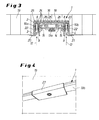
- mounting busbar 1 is provided by an extruded profile 2, for example made of aluminum, and has an approximately rectangular outer cross-section. Including the two flanges 3,4 of the extruded profile 2, a vertically extending chamber 5, 6 is formed in the interior of the built-in busbar 1 on the left and right sides.
- the two thus outer chambers 5, 6 are open at the bottom and each take at least one live conductor element 7, which - as not shown here - over the entire length of the mounting busbar 1, which can be manufactured in different lengths ,
- the conductor element 7 consists of an embedded in an insulator 8 spring slot terminal 9, which has a left and right side, live contact surface 10a, 10b.
- the insulator 8 isolates the spring slot terminals 9 electrically from the chambers 5, 6 and is secured via locking lugs 11 a, 11 b securely within the chambers 5, 6.
- the gap widths of the chambers 5, 6 and the gap widths of the spring slot clamps 9 are designed so narrow that they are inaccessible especially for fingers.
- busbar 1 For connection to the built-in busbar 1 has an electrical load, such as a sub-base 27 (see Fig. 4 ), not shown here Stromab reviewingmelde having a complementary to the opposite chambers 5, 6 distance.
- the current collector contacts are inserted for electrical current decrease from below in the direction of arrow 12 in the chambers 5, 6 and subsequently clamped securely between the contact surfaces 10a, 10b of the spring slot terminals 9.
- adapter can be provided, which are plugged with corresponding current collector contacts in the spring slot terminals 9 of the chambers 5, 6.
- a 13a equipped with LEDs board 14 is arranged, which is guided in slot-shaped openings 15 of a U-shaped insulator 16.
- the insulator 16 is securely held between the chambers 5, 6 of the extruded profile 2 by latching projections 17a, 17b and extends with the circuit board 14 over the entire length of the mounting busbar 1 (see Fig.1 ).
- the LEDs 13a thus form a light strip or a light strip 13b, which serves in particular the indirect illumination of premises or objects, while extending transversely across the board 14 with the LEDs 13a and into the spring slot terminals 9 of the chambers 5, 6 inserted sub-base 27 of the spot or partial illumination is used (see Fig. 4 ).
- the LEDs 13a are fed by a separate voltage source, not shown here, so that it is possible for the LEDs 13a and the spring slit terminals 9 fed under the luminaire 27 separately or together switched on or off.
- the built-in busbar is installed in a mounting channel 18 a ceiling 19.
- the flanges 3, 4 are formed with projecting outwardly web surfaces 20, 21, which lie flat on the ceiling 19 after complete installation of the mounting busbar 1.
- the flanges 3, 4 are provided on their outer sides with sawtooth-shaped projections 22 which interlock with the ceiling material, such as plaster.
- the web 23 of the built-in busbar 1 is formed on its upper side with spacer ribs 24 which rest on the base 25 of the installation channel 18 and the ceiling 19 (see Fig.1 ).
- spacer ribs 24 which rest on the base 25 of the installation channel 18 and the ceiling 19 (see Fig.1 ).
Landscapes
- Arrangement Of Elements, Cooling, Sealing, Or The Like Of Lighting Devices (AREA)
Priority Applications (1)
| Application Number | Priority Date | Filing Date | Title |
|---|---|---|---|
| EP13000110.0A EP2755286A1 (fr) | 2013-01-10 | 2013-01-10 | Rails conducteurs de montage |
Applications Claiming Priority (1)
| Application Number | Priority Date | Filing Date | Title |
|---|---|---|---|
| EP13000110.0A EP2755286A1 (fr) | 2013-01-10 | 2013-01-10 | Rails conducteurs de montage |
Publications (1)
| Publication Number | Publication Date |
|---|---|
| EP2755286A1 true EP2755286A1 (fr) | 2014-07-16 |
Family
ID=47713796
Family Applications (1)
| Application Number | Title | Priority Date | Filing Date |
|---|---|---|---|
| EP13000110.0A Withdrawn EP2755286A1 (fr) | 2013-01-10 | 2013-01-10 | Rails conducteurs de montage |
Country Status (1)
| Country | Link |
|---|---|
| EP (1) | EP2755286A1 (fr) |
Cited By (1)
| Publication number | Priority date | Publication date | Assignee | Title |
|---|---|---|---|---|
| EP3462084A1 (fr) * | 2017-09-29 | 2019-04-03 | LED Linear GmbH | Lampe à del |
Citations (10)
| Publication number | Priority date | Publication date | Assignee | Title |
|---|---|---|---|---|
| GB394199A (en) * | 1932-10-12 | 1933-06-22 | Aldo Franco Pessina | Improvements in electric lines |
| US2072702A (en) * | 1934-04-16 | 1937-03-02 | Charles G Beersman | Electrical outlet device |
| US2072703A (en) * | 1934-11-24 | 1937-03-02 | Charles G Beersman | Electrical outlet device |
| DE2346814A1 (de) * | 1973-09-18 | 1975-04-03 | Brandenburg Co Nova Lux | Stromabnehmereinrichtung fuer stromschienen mit einstellbarer phasenanzapfung |
| DE29912354U1 (de) * | 1999-07-15 | 1999-11-25 | Interluebke Gebr Luebke Gmbh & | Beleuchtungseinrichtung für ein Schrankmöbel |
| WO2004011849A1 (fr) * | 2002-07-30 | 2004-02-05 | L & S S.R.L. | Dispositif d'eclairage dote d'une piste electrifiee et d'elements d'eclairage a haut rendement |
| DE202008011979U1 (de) * | 2008-04-01 | 2008-12-11 | Lebensstil Technology Co., Ltd. | Montageanordnung eines Leuchtkörpers |
| GB2459380A (en) * | 2008-04-22 | 2009-10-28 | Keith Rigby | Device for concealing gaps and/or cracks |
| DE202012004156U1 (de) * | 2012-04-13 | 2012-07-23 | Andreas Hierzer | Adaptervorrichtung für eine Leuchte einer Stromschienenanordnung und Stromschienenanordnung |
| DE102011017702A1 (de) * | 2011-04-28 | 2012-10-31 | Zumtobel Lighting Gmbh | Lichtbandsystem und Konvertereinheit hierfür |
-
2013
- 2013-01-10 EP EP13000110.0A patent/EP2755286A1/fr not_active Withdrawn
Patent Citations (10)
| Publication number | Priority date | Publication date | Assignee | Title |
|---|---|---|---|---|
| GB394199A (en) * | 1932-10-12 | 1933-06-22 | Aldo Franco Pessina | Improvements in electric lines |
| US2072702A (en) * | 1934-04-16 | 1937-03-02 | Charles G Beersman | Electrical outlet device |
| US2072703A (en) * | 1934-11-24 | 1937-03-02 | Charles G Beersman | Electrical outlet device |
| DE2346814A1 (de) * | 1973-09-18 | 1975-04-03 | Brandenburg Co Nova Lux | Stromabnehmereinrichtung fuer stromschienen mit einstellbarer phasenanzapfung |
| DE29912354U1 (de) * | 1999-07-15 | 1999-11-25 | Interluebke Gebr Luebke Gmbh & | Beleuchtungseinrichtung für ein Schrankmöbel |
| WO2004011849A1 (fr) * | 2002-07-30 | 2004-02-05 | L & S S.R.L. | Dispositif d'eclairage dote d'une piste electrifiee et d'elements d'eclairage a haut rendement |
| DE202008011979U1 (de) * | 2008-04-01 | 2008-12-11 | Lebensstil Technology Co., Ltd. | Montageanordnung eines Leuchtkörpers |
| GB2459380A (en) * | 2008-04-22 | 2009-10-28 | Keith Rigby | Device for concealing gaps and/or cracks |
| DE102011017702A1 (de) * | 2011-04-28 | 2012-10-31 | Zumtobel Lighting Gmbh | Lichtbandsystem und Konvertereinheit hierfür |
| DE202012004156U1 (de) * | 2012-04-13 | 2012-07-23 | Andreas Hierzer | Adaptervorrichtung für eine Leuchte einer Stromschienenanordnung und Stromschienenanordnung |
Cited By (1)
| Publication number | Priority date | Publication date | Assignee | Title |
|---|---|---|---|---|
| EP3462084A1 (fr) * | 2017-09-29 | 2019-04-03 | LED Linear GmbH | Lampe à del |
Similar Documents
| Publication | Publication Date | Title |
|---|---|---|
| DE102010032383B4 (de) | Stromschienenverbinder und Stromschienensystem mit mindestens zwei benachbarten Stromschienen und einem Stromschienenverbinder | |
| DE202016008190U1 (de) | Beleuchtungsanordnung für Stromschienen | |
| DE102012007086B4 (de) | Kupplung für eine Stromschiene sowie Anordnung mehrerer solcher Kupplungen | |
| AT515246B1 (de) | Profilleuchtensystem und Montageverfahren dafür | |
| DE102016104649B4 (de) | Leuchte für ein modulares Leuchtsystem, modulares Leuchtsystem sowie Verbindungsstück | |
| DE102010055789A1 (de) | Stromschienenverbinder und Stromschienensystem mit mindestens zwei benachbarten Stromschienen und einem Stromschienenverbinder | |
| DE102014005715A1 (de) | Schublade | |
| EP1299927B1 (fr) | Element profile a barre conductrice | |
| EP0486714A1 (fr) | Rail pour appareils d'éclairage | |
| DE202013000183U1 (de) | Einbau-Stromschine | |
| DE19603960B4 (de) | Mehrpoliger Abzweig-Steckverbinder | |
| DE102005023452B4 (de) | Montage- und Verdrahtungssystem für elektrische Funktionsmodule, insbesondere für Schaltgeräte | |
| EP2755286A1 (fr) | Rails conducteurs de montage | |
| EP1886603B1 (fr) | Dispositif à emboîter, objet d'emboîter et ensemble comprenant un dispositif à emboîter et un objet d'emboîter | |
| DE102005040859A1 (de) | Konfigurierbares Strom- & Lichtschienensystem | |
| DE202006000425U1 (de) | Beleuchtungssystem, sein Leuchtmittel und Einspeisung zum Betrieb dieses Leuchtmittels | |
| AT516443A2 (de) | Leuchte mit Kontaktierungsmodul | |
| EP4122058B1 (fr) | Bande lumineuse à éléments d'éclairage connectés | |
| DE3806241A1 (de) | Installationseinrichtung fuer niedervolt-leuchten | |
| DE2538199A1 (de) | Anschlussklemme fuer elektrische leitungen | |
| AT17489U1 (de) | Lichtbandsystem mit länglicher Trägeranordnung und mehreren Leuchteneinheiten | |
| DE10011250C2 (de) | Anschlusseinrichtung mit einer Halterung für eine Halogenlampe an sog. Niedervolt-Stangen- oder Seilsystemen | |
| DE19615372C2 (de) | Montagekasten mit einer Lampenfassung für Zweistift-Leuchtstofflampen oder dergleichen | |
| DE102015007037B3 (de) | Sicherungskasten für Leitungsschutzsicherungen von Leuchten | |
| DE202014102284U1 (de) | Installationsdose sowie Installationssystem |
Legal Events
| Date | Code | Title | Description |
|---|---|---|---|
| PUAI | Public reference made under article 153(3) epc to a published international application that has entered the european phase |
Free format text: ORIGINAL CODE: 0009012 |
|
| 17P | Request for examination filed |
Effective date: 20130110 |
|
| AK | Designated contracting states |
Kind code of ref document: A1 Designated state(s): AL AT BE BG CH CY CZ DE DK EE ES FI FR GB GR HR HU IE IS IT LI LT LU LV MC MK MT NL NO PL PT RO RS SE SI SK SM TR |
|
| AX | Request for extension of the european patent |
Extension state: BA ME |
|
| STAA | Information on the status of an ep patent application or granted ep patent |
Free format text: STATUS: THE APPLICATION IS DEEMED TO BE WITHDRAWN |
|
| 18D | Application deemed to be withdrawn |
Effective date: 20150117 |