EP2752095B1 - Personalisierte beleuchtung für eine freifläche - Google Patents
Personalisierte beleuchtung für eine freifläche Download PDFInfo
- Publication number
- EP2752095B1 EP2752095B1 EP12826631.9A EP12826631A EP2752095B1 EP 2752095 B1 EP2752095 B1 EP 2752095B1 EP 12826631 A EP12826631 A EP 12826631A EP 2752095 B1 EP2752095 B1 EP 2752095B1
- Authority
- EP
- European Patent Office
- Prior art keywords
- light source
- light
- lighting
- target area
- modules
- Prior art date
- Legal status (The legal status is an assumption and is not a legal conclusion. Google has not performed a legal analysis and makes no representation as to the accuracy of the status listed.)
- Active
Links
Images


Classifications
-
- H—ELECTRICITY
- H05—ELECTRIC TECHNIQUES NOT OTHERWISE PROVIDED FOR
- H05B—ELECTRIC HEATING; ELECTRIC LIGHT SOURCES NOT OTHERWISE PROVIDED FOR; CIRCUIT ARRANGEMENTS FOR ELECTRIC LIGHT SOURCES, IN GENERAL
- H05B47/00—Circuit arrangements for operating light sources in general, i.e. where the type of light source is not relevant
- H05B47/10—Controlling the light source
- H05B47/105—Controlling the light source in response to determined parameters
-
- H—ELECTRICITY
- H05—ELECTRIC TECHNIQUES NOT OTHERWISE PROVIDED FOR
- H05B—ELECTRIC HEATING; ELECTRIC LIGHT SOURCES NOT OTHERWISE PROVIDED FOR; CIRCUIT ARRANGEMENTS FOR ELECTRIC LIGHT SOURCES, IN GENERAL
- H05B45/00—Circuit arrangements for operating light-emitting diodes [LED]
- H05B45/10—Controlling the intensity of the light
-
- H—ELECTRICITY
- H05—ELECTRIC TECHNIQUES NOT OTHERWISE PROVIDED FOR
- H05B—ELECTRIC HEATING; ELECTRIC LIGHT SOURCES NOT OTHERWISE PROVIDED FOR; CIRCUIT ARRANGEMENTS FOR ELECTRIC LIGHT SOURCES, IN GENERAL
- H05B47/00—Circuit arrangements for operating light sources in general, i.e. where the type of light source is not relevant
- H05B47/10—Controlling the light source
- H05B47/155—Coordinated control of two or more light sources
Definitions
- Embodiments of the present invention generally relate to the field of lighting, and more particularly, to a lighting system, and to a method, an apparatus, a controller, and a computer program product for controlling the illuminance of a target area in the lighting system.
- the light sources In an open area, such as an open-plan office or factory, there are usually several light sources arranged for general lighting.
- the light sources such as luminaries, are fixed at predetermined positions on the ceiling.
- the light sources are generally fixed and have little possibility to be changed.
- the light for a target area is usually coming from several luminaries; thus positions of the luminaires will affect the illuminance of the target area. Also, lighting distribution of the luminaires will have effect on the illuminance of the target area. Another factor which will further affect the illuminance of the target area is the output level of each of the luminaires.
- Patent application WO 2011033444 A1 relates to a method for controlling a light distribution in a space to match a predefined target luminance level.
- the luminance level of light from said light sources is measured at different measuring areas within the space.
- a weighed luminance level is determined for each of the measuring areas based on the measured luminance levels, where the weighted luminance level indicates the contribution from the light sources to the measured luminance level at the different measuring areas.
- This weighed luminance level is used as a tuning parameter for tuning the emitted light at the installed light sources such that the weighed luminance level at each of the different measuring areas substantially matches a pre-defined target luminance level at the different measuring areas.
- Patent application ES 2272180 A1 relates to an illumination system comprising a matrix of individually controllable light emitters.
- the light emitters are grouped, wherein each group is associated with a means configured to guide the light emitted by the light emitters in a desired direction.
- a control system can establish, modify and move an illuminated zone in different directions along a surface, for example, an operating table.
- the present invention proposes a novel solution for controlling the illuminance of a target area in a lighting system.
- embodiments of the present invention provide a method of controlling the illuminance of a target area in a lighting system, wherein the lighting system comprises at least one light source and each of the at least one light source comprises a plurality of light modules, each of the plurality of light modules being adjustable independently, wherein different light modules within each of the at least one light source differ in terms of lighting direction, the method comprising: selecting at least one light module, which is associated with the illuminance of the target area, from the at least one light source based on position relationships between each of the at least one light source and the target area and lighting distributions of each of the at least one light source; and adjusting at least one of the selected at least one light module, characterized in that the selecting of at least one light module comprises: obtaining the position relationships between each of the at least one light source and the target area, each position relationship representing a relationship between a position of a respective light source and a position of the target area; obtaining the lighting distributions of the at least one light source, each lighting distribution referring to
- embodiments of the present invention provide an apparatus for controlling the illuminance of a target area in a lighting system, wherein the lighting system comprises at least one light source and each of the at least one light source comprises a plurality of light modules, each of the plurality of light modules being adjustable independently, wherein different light modules within each of the at least one light source differ in terms of lighting direction, the apparatus comprising: a selector configured to select at least one light module, which is associated with the illuminance of the target area, from the at least one light source based on position relationships between each of the at least one light source and the target area and lighting distributions of each of the at least one light source; and an adjustor configured to adjust at least one of the selected at least one light module, characterized in that the selector is configured to obtain the lighting distributions of the at least one light source, each lighting distribution referring to a light intensity of a respective light source in respective directions, wherein the selector comprises: a first obtaining unit configured to obtain the position relationships between each of the at least one light
- embodiments of the present invention provide a controller for controlling the illuminance of a target area in a lighting system, wherein the lighting system comprises at least one light source and each of the at least one light source comprises a plurality of light modules; each of the plurality of light modules being adjustable independently.
- the controller comprises an apparatus according to the present invention.
- embodiments of the present invention provide a computer program product comprising a computer program that is tangibly embodied on a computer-readable medium.
- the computer program is configured to carry out the method computer-readable medium.
- the computer program is configured to carry out the method according to the present invention.
- inventions of the present invention provide a lighting system.
- the lighting system comprises: at least one light source, each of the at least one light source comprising a plurality of light modules and each of the plurality of light modules being adjustable independently; and a controller configured to control the illuminance of a target area in the lighting system, comprising an apparatus according to the present invention.
- a lighting solution with only general lighting like grille lighting in the ceiling
- each block in the flowcharts or block diagrams may represent a module, a program, or a part of code, which contains one or more executable instructions for performing specified logic functions.
- functions indicated in blocks may occur in an order differing from the order as illustrated in the figures. For example, two blocks illustrated consecutively may actually be performed in parallel or inverse order, which depends on the related functions.
- block diagrams and/or each block in the flowcharts and a combination of thereof may be implemented by a dedicated hardware-based system for performing specified functions/operations or by a combination of dedicated hardware and computer instructions.
- embodiments of the present invention provide a lighting system and provide a method, an apparatus, a controller, and a computer program product for controlling the illuminance of a target area in the lighting system.
- FIG. 1 where a high-level block diagram illustrating a lighting system 100 in accordance with an exemplary embodiment of the present invention is shown.
- the lighting system may comprise at least one light source and a controller for controlling them.
- the lighting system 100 comprises five light sources 110, 120, 130, 140 and 150 (e.g. 5 luminaires), as well as a controller 160.
- each of the light sources may comprise a plurality of light modules (not shown; and for example 10 light modules) and each of the plurality of light modules may be adjustable independently.
- an output level of each light module in a light source may be adjustable independently from other light modules. Accordingly, when the output level of a light module is adjusted, the output levels of other light modules would not be affected. As would be appreciated by those skilled in the art, the lighting direction or other suitable factor of a light module in a light source may also be adjustable independently.
- LEDs may serve as the light emitting elements in a light module.
- OLEDs organic light emitting diodes
- fluorescents may be used in connection with the embodiments of the present invention.
- light sources which contribute to the illuminance of a target area are considered as being associated with the target area.
- the light emitted by the light sources 110, 120, 130, 140 and 150 will illuminate a target area 101, which may be predetermined in an open area where the lighting system 100 is built up.
- light sources 110, 120, 130, 140 and 150 are associated with the illuminance of the target area.
- a target area in the present invention may be a work place, a study place, a target object, or any other place used by a person.
- the controller 160 may be configured to control the illuminance of the target area 101 in the lighting system 100.
- the controller 160 may comprise an apparatus (not shown) for controlling the illuminance of a target area in a lighting system.
- the apparatus may comprise a selector and an adjustor.
- the selector may select at least one light module, which is associated with the illuminance of the place, from the at least one light source that is based on the position relationship between the at least one light source and the target area and a lighting distribution of each of the at least one light source; and the adjustor may adjust at least one of the selected at least one light module. Details of the apparatus will be described with respect to FIG. 12 as below.
- controller 160 may be configured to implement functionalities as described with reference to the method and apparatus according to the present invention. Therefore, the features discussed with respect to the method according to the present invention apply to the corresponding components in the controller 160. It is further noted that the controller 160 may be embodied in hardware, software, firmware, and/or any combination thereof. For example, the controller 160 may be implemented by using a circuit implemented in hardware, a processor, a computer or a server with computer programs configured to carry out the method according to the present invention, or any other appropriate device implemented in hardware or software. Those skilled in the art will appreciate that the aforesaid examples are only for illustration not limitation.
- the controller according to the present invention may comprise at least one processor.
- the at least one processor suitable for use with embodiments of the present disclosure may include, by way of example, both general and special-purpose processors that are already known or will be developed in the future.
- the controller 160 may further comprise at least one memory.
- the at least one memory may include, for example, semiconductor memory devices, e.g. RAM, ROM, EPROM, EEPROM, and flash memory devices.
- the at least one memory may be used to store programs of computer executable instructions.
- the program can be written in any high-level and/or low-level compliable or interpretable programming languages.
- the computer executable instructions may be configured, with the at least one processor, to cause the controller 160 to at least perform the methods according to the present invention.
- the controller according to the present invention may perform wireless control or wired control on the light source(s) in the lighting system.
- wireless control may adopt a number of wireless technologies including, for example, WiFi, Low-Power WiFi, Bluetooth, EnOcean, Z-Wave and similar technologies, which typically permit short range communication.
- the lighting system may be the lighting system 100 as illustrated in FIG. 1 , which comprises at least one light source, each of the at least one light source comprises a plurality of light modules, and each of the plurality of light modules is adjustable independently.
- At step S201 at least one light module, which is associated with the illuminance of a target area, is selected from the at least one light source based on the position relationship between the at least one light source and the target area and a lighting distribution of each of the at least one light source.
- the position relationship between the at least one light source and the target area generally represents the relationship between the position of the at least one light source and the position of the target area.
- the position relationship may comprise position information on the at least one light source and on the target area, e.g. three-dimensional coordinate information, which comprises the coordinate of the at least one light source and the coordinate of the target area.
- the position relationship may also comprise direction information on the at least one light source and on the target area, e.g. one or more directional angles which represent the angles between the at least one light source and on the target area.
- the position relationship may be stored in advance in a memory.
- the position relationship may include association between the target area and one or more light sources.
- the position relationship may include association between the target area and one or more light modules in the light sources. By looking up in the stored position relationship, at least one light module which is associated with the target area may be determined.
- the position relationship may be obtained based on positions of the target area and the at least one light source.
- at least one relative direction of the target area may be calculated from the at least one light source, and the position relationship between the at least one light source and the target area may be obtained based on the at least one relative direction.
- the lighting distribution refers to the light intensity of a light source in respective directions in a space.
- the lighting distribution of a light source may be in a form of a triangle, a droplet, a sector, or any other suitable shape.
- the lighting distribution may comprise a plurality of parts (for example N parts, where N ⁇ 2), and each part may correspond to one of the plurality of light modules in a light source.
- I i-0 may be used to describe the output level of each light module of a light source; ⁇ is a parameter to describe the direction of work place from each light module of a light source.
- one or more light modules may be selected from the at least one light source in various ways.
- the one or more light sources may be selected by means of: obtaining, from the position relationship, a relative direction of the target area from a light source; obtaining, from the lighting distribution of the light source, lighting directions of a plurality of light modules emitting from the light source; comparing the relative direction with the lighting directions; and selecting one light module from the plurality of light modules of the light source based on the comparison results.
- the one or more light modules which are associated with the illuminance of a target area may be determined in advance based on the position relationship between the at least one light source and the target area and a lighting distribution of each of the at least one light source and stored in a memory or storage device, including, for example, semiconductor memory devices, e.g., RAM, ROM, EPROM, EEPROM, and flash memory devices.
- a memory or storage device including, for example, semiconductor memory devices, e.g., RAM, ROM, EPROM, EEPROM, and flash memory devices.
- the one or more light modules, which are associated with the illuminance of a target area may be selected from the at least one light source by looking up in the memory or storage device.
- At step S202 at least one of the selected at least one light module is adjusted.
- the selected at least one light module may be adjusted in various ways.
- the selected at least one light module may be adjusted dependently or independently from each other.
- a subset of the selected at least one light module may be adjusted.
- lighting requirement for the target area may be obtained and the selected at least one light module may be adjusted in proportion or independently to meet the lighting requirement.
- lighting requirement for the target area may be obtained and a portion or all of the selected at least one light module may be adjusted to meet the lighting requirement.
- the light module may comprise at least one light emitting element.
- a light emitting element may be a LED, an OLED, a fluorescent or any other suitable element.
- the lighting system may be the lighting system 100 as illustrated in FIG. 1 , which comprises at least one light source, each of the at least one light source comprises a plurality of light modules, and each of the plurality of light modules is adjustable independently.
- step S301 lighting requirement for the target area is obtained.
- the lighting requirement may be predefined or inputted by a user according to his/her preference or experience.
- the lighting requirement may be pre-stored in advance in a memory, which may be, for example, semiconductor memory devices (e.g., RAM, ROM, EPROM, EEPROM, etc.), flash memory devices, and so on; and the lighting requirement may be obtained when the illuminance of a target area is to be adjusted.
- a memory which may be, for example, semiconductor memory devices (e.g., RAM, ROM, EPROM, EEPROM, etc.), flash memory devices, and so on; and the lighting requirement may be obtained when the illuminance of a target area is to be adjusted.
- the lighting requirement may be received from an interface between the user and the lighting system, and the interface may be a graphic user interface (GUI), a remote controller, a portable device, a computer or any other suitable device available for those skilled in the art to enter their requirement for the illuminance of the place.
- GUI graphic user interface
- a relative direction of the target area from a light source is obtained from the position relationship.
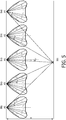
- a relative direction is a parameter to describe the direction of work place from a light source. Only for the purpose of illustration, it is assumed that the lighting system comprises 5 light sources, and each light source comprises 10 light modules, as illustrated in FIG.5 . Reference is now made to FIG. 5 , where a schematic diagram illustrating the controlling of illuminance of a target area 501 in a lighting system in accordance with an exemplary embodiment of the present invention is shown, and where the lighting system comprises 5 light sources 510, 520, 530, 540 and 550, denoted as A1, A2, A3, A4 and A5 for brevity purposes.
- ⁇ Ai a relative direction of the target area from a light source
- i 1, 2, ..., 5.
- the ⁇ Ai may be calculated as the angle between the first line and the second line.
- ⁇ A1 , ⁇ A2 , ⁇ A3 , ⁇ A4 and ⁇ A5 representing the relative directions of the target area from the light sources A1, A2, A3, A4 and A5, may be obtained respectively.
- the position relationship may be obtained in several ways.
- the position relationship may be obtained by first calculating at least one relative direction of the target area from the at least one light source, and then obtaining the position relationship based on the at least one relative direction.
- the position relationship between a light source and the target area may be obtained in advance and stored in a memory or storage device, for future use.
- the position relationship may be calculated in real time in the process of the method according to the present invention.
- step S303 lighting directions of a plurality of light modules emitting from the light source are obtained from lighting distribution of the light source.
- any of the relative directions ⁇ A1 , ⁇ A2 , ⁇ A3 , ⁇ A4 and ⁇ A5 may be obtained from the position relationship. Only for the purpose of illustration, it is assumed that at step S302, the relative direction, e.g. ⁇ A4 of the target area from light source 540, i.e. A4, is obtained from the position relationship. Thus, at step S303, lighting directions of a plurality of light modules emitting from light source 540 may be obtained from the lighting distribution of the light source 540.
- the lighting distribution of the light source 540 may be in a droplet-like form as shown in FIG. 4 .
- the lighting distribution of the light source 540 may also comprise 10 parts, denoted as I 1 , I 2 , I 3 ,..., I 8 , I 9 , I 10 respectively, wherein each part corresponds to each light module in the light source 510.
- each light module emits light and accordingly has a lighting scope, which corresponds to a range of angle.
- the lighting directions of all light modules in the light source 540 may be obtained.
- a lighting direction of a light module emitting from a light source is, for example, the range of angle.
- the maximum in the range of angle may be the angle (denoted as ⁇ I1_max in FIG. 4 ) between the light 420 (which is the furthest light emitted from the first light module corresponding to the part I 1 ) and the perpendicular line 410 of the light source.
- the minimum in the range of angle may be the angle (denoted as ⁇ I1_min in FIG. 4 ) between the light 430 (which is the nearest light emitted from the first light module corresponding to the part I1) and the central perpendicular line 410 of the light source.
- the relative direction is compared with the lighting directions.
- the relative direction e.g. ⁇ A4 of the target area from light source 540
- the relative direction may be compared with respective lighting directions of 10 light modules emitting from the light source 540. Based on this comparison, it is easy to determine the relative direction, which is most relative to the lighting direction of the light module in the light source 540.
- the relative direction ⁇ A4 may be compared with the lighting direction of the first light module (corresponding to part I 1 ) in the light source 540, with the lighting direction of the second light module (corresponding to part I 2 ) in the light source 540,..., with the lighting direction of the tenth light module (corresponding to part I 10 ) in the light source 540.
- ⁇ A4 falls into the range of ⁇ I1_max to ⁇ I1_min ; it can be determined that the first light module which corresponds to the part I 1 contributes to the illuminance of the place.
- the relative direction ⁇ A4 is most relative to the part I 1 .
- one light module is selected from the plurality of light modules of the light source based on the comparison results.
- the relative direction, e.g. ⁇ A4 is most relative to the part I 1 , thus the light module, which corresponds to the part I 1 , in the light source 540 may be selected from the plurality of light modules of the light source.
- steps S302 to S305 the light source 540 is taken, for example, as the light source recited in these steps only for the purpose of illustration; those skilled in the art will readily understand that any one of the light sources 510, 520, 530, 540 and 550 is applicable to the process of steps S302 to S305.
- a light module (for example, corresponding to part I 5 ) may be selected from the light source 510, a light module (for example, corresponding to part I 2 ) may be selected from the light source 520, a light module (for example, corresponding to part I 9 ) may be selected from the light source 530 and a light module (for example, corresponding to part I 10 ) may be selected from the light source 550.
- the lighting requirement for the target area may define the desired illuminance of the area.
- the desired illuminance may be obtained from the lighting requirement, and then the output level of at least one of the selected light modules may be adjusted, based on the relationship between the output level and the illuminance, to meet the lighting requirement.
- the output level of a light module may be adjusted by various ways, e.g. by increasing or reducing the voltage or the current of a light module, or by any other means known in the art.
- the relationship between the output level and the illuminance may have a different form, depending on the concrete scenario of the lighting system. For example, with respect to the lighting system as illustrated in FIG.
- E I A 5 ⁇ 10 ⁇ A 5 ⁇ cos ⁇ A 5 3 H 2 + I A 3 ⁇ 9 ⁇ A 3 ⁇ cos ⁇ A 3 3 H 2 + I A 1 ⁇ 5 ⁇ A 1 ⁇ cos ⁇ A 1 3 H 2 + I A 2 ⁇ 2 ⁇ A 2 ⁇ cos ⁇ A 2 3 H 2 + I A 4 ⁇ 1 ⁇ A 4 ⁇ cos ⁇ A 4 3 H 2
- H indicates the height of each light source with respect to the ground
- I A1-5 ( ⁇ A1 ) indicates the output level of part I 5 in the lighting distribution of the light source A1
- I A2-2 ( ⁇ A2 ) indicates the output level of
- the at least one light module is adjusted in proportion to meet the lighting requirement.
- the output levels of the five light modules (corresponding to I 5 in A1, I 2 in A2, I 9 in A3, I 1 in A4 and I 10 in A5) may be multiplied with a parameter, wherein the parameter is less than 1 when there is a need to reduce the illuminance of the place, and the parameter exceeds 1 when there is a need to increase the illuminance of the place.
- the concrete value of the parameter depends on several factors, such as the form of the relationship between the output level and the illuminance, and the parameter may be worked out with respect to a concrete scenario.
- the at least one light module is adjusted independently to meet the lighting requirement.
- the output level(s) of one or more of the five light modules may be reduced or increased when there is a need to reduce or increase the illuminance of the place.
- the output level of the light module corresponding to I 5 in A1 is adjusted and the remaining four light modules (corresponding to I 2 in A2, I 9 in A3, I 1 in A4 and I 10 in A5) are unchanged.
- At least one light module may be adjusted in various ways to meet the lighting requirement; for example, a portion of (or all of) the light module(s) may be adjusted according to the lighting requirement.
- the above embodiments are illustrative and exemplary, but not for purpose of limitation.
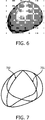
- FIG. 6 where a schematic diagram illustrating an example in three dimensions of lighting distribution of a light source in accordance with an exemplary embodiment of the present invention is shown. It can be seen from FIG. 6 that the lighting distribution of a light source may be in a form of a droplet in three dimensions (3D).
- FIG. 7 a schematic diagram illustrating a front view and a side view of a lighting distribution in accordance with an exemplary embodiment of the present invention is shown.
- the front view is denoted as 701 and the side view is denoted as 702, as shown in FIG. 7 .
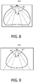
- FIG. 8 a schematic diagram illustrating a cross section of a lighting distribution in the front view in accordance with an exemplary embodiment of the present invention is shown.
- the lighting distribution in the front view may be divided in several parts (for example, which may be similar as I 1 , I 2 , I 3 ,..., I 8 , I 9 , I 10 , as shown in FIG. 4 ), and each part corresponds to each light module in a light source.
- a light source comprises multiple light modules, and a light module emits light and accordingly has a lighting scope, which corresponds to a range of angle ⁇ .
- the lighting distribution in the front view may be uniformly divided into several parts (for example, 8 parts), each part corresponding to a light module in the light source.
- the angle ⁇ may be illustrated as ⁇ 1 , ⁇ 2 , ⁇ 8 .
- ⁇ 1 and ⁇ 2 are shown in FIG. 8 , where, for example, 0° ⁇ ⁇ 1 ⁇ 15°, and -15° ⁇ ⁇ 2 ⁇ 0°; and those skilled in the art will readily understand the range of other angles. It is noted that in this example, ⁇ 2 is symmetrical to ⁇ 1 with respect to the central perpendicular line 810 of the light source, thus the value of ⁇ 2 is negative.
- FIG. 9 a schematic diagram illustrating a cross section of a lighting distribution in the side view, in accordance with an exemplary embodiment of the present invention, is shown.
- a light module emits light and accordingly has a lighting scope, which corresponds to a range of angle ⁇ , and the lighting distribution in the side view may be uniformly divided into several parts (for example, 6 parts), each part corresponding to a light module in the light source.
- the angle ⁇ may be illustrated as ⁇ 1 , ⁇ 2 , ... ⁇ 6 .
- ⁇ 1 and ⁇ 2 are shown in FIG. 9 , where, for example, 0° ⁇ ⁇ 1 ⁇ 20° and - 20° ⁇ ⁇ 2 ⁇ 0°; and those skilled in the art will readily understand the range of other angles.
- ⁇ 2 is symmetrical to ⁇ 1 with respect to the central perpendicular line 910 of the light source; thus the value of ⁇ 2 is negative.
- FIG. 10 where a schematic diagram illustrating the controlling of the illuminance of a target area in accordance with an exemplary embodiment of the present invention is shown.
- the target area is denoted as 1001 and a light source is denoted as 1002.
- a light module which is associated with the illuminance of the target area 1001, from the light source 1002 based on the position relationship between the light source and the target area 1001 and the lighting distribution of the light source 1002.
- the position relationship between a target area 1001 and a light source 1002 may comprise a distance between a point O and a point A on the ground (also called as “distance OA"), a distance between a point O and a point B on the ground (also called as “distance OB").
- An exemplary embodiment for calculating the distances may refer to FIG. 11 , where a schematic diagram illustrating the position relationship between a target area 1101 and a light source 1102 in accordance with an exemplary embodiment of the present invention is shown.
- the distance OA may be calculated by H ⁇ tan( ⁇ )
- the distance OB may be calculated by H ⁇ tan( ⁇ ).
- FIG. 12 a schematic diagram illustrating an apparatus 1200 for controlling the illuminance of a target area in a lighting system in accordance with an exemplary embodiment of the present invention is shown.
- the lighting system may be the lighting system 100 as illustrated in FIG. 1 , which comprises at least one light source, each of the at least one light source comprises a plurality of light modules, and each of the plurality of light modules is adjustable independently.
- the apparatus 1200 may comprise two components: a selector 1210 and an adjustor 1220.
- the selector 1210 may be configured to select at least one light module, which is associated with the illuminance of the area, from the at least one light source based on the position relationship between the at least one light source and the target area and a lighting distribution of each of the at least one light source; and the adjustor 1220 may be configured to adjust at least one of the selected at least one light module.
- the selector 1210 may comprise: a calculating unit configured to calculate at least one relative direction of the target area from the at least one light source; and a first obtaining unit configured to obtain the position relationship between the at least one light source and the target area based on the at least one relative direction.
- the selector 1210 may comprise: a second obtaining unit configured to obtain, from the position relationship, a relative direction of the target area from a light source; a third obtaining unit configured to obtain, from the lighting distribution of the light source, lighting directions of a plurality of light modules emitting from the light source; a comparing unit configured to compare the relative direction with the lighting directions; and a selecting unit configured to select one light module from the plurality of light modules of the light source based on the comparison results.
- the adjustor 1220 may comprise: a first adjusting unit configured to adjust in proportion or independently the at least one light module to meet a lighting requirement.
- the lighting distribution of a light source may be in a form of a triangle, a droplet, or a sector.
- a light module may comprise at least one light emitting element.
- a light emitting element may be a LED, an OLED or a fluorescent.
- the apparatus 1200 may be configured to implement functionalities, as described with reference to FIGs. 2 and 3 . Therefore, the features discussed with respect to methods of the present invention, such as methods 200 and 300, apply to the corresponding components of the apparatus 1200. It is further noted that the components of the apparatus 1200 may be embodied in hardware, software, firmware, and/or any combination thereof. For example, the components of the apparatus 1200 may be respectively implemented by a circuit, a processor or any other appropriate device. Those skilled in the art will appreciate that the aforesaid examples are only for the purpose of illustration, not as limitation.
- the apparatus 1200 comprises at least one processor.
- the at least one processor suitable for use with embodiments of the present disclosure may include, by way of example, both general and special-purpose processors that are already known or will be developed in the future.
- the apparatus 1200 further comprises at least one memory.
- the at least one memory may include, for example, semiconductor memory devices, e.g., RAM, ROM, EPROM, EEPROM, and flash memory devices.
- the at least one memory may be used to store program of computer executable instructions.
- the program can be written in any high-level and/or low-level compliable or interpretable programming languages.
- the computer executable instructions may be configured, with the at least one processor, to cause the apparatus 1200 to at least perform according to methods of the present invention, such as methods 200 or 300 as discussed above.
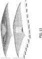
- FIG. 13 a schematic diagram illustrating an exemplary illuminance result in accordance with an exemplary embodiment of the present invention and the desired illuminance result is shown.
- the bottom part illustrates a desired illuminance distribution for a target area and the upper part illustrates an illuminance distribution for a target area which is obtained according to the present invention.
- the desired illuminance distribution makes it possible to reduce the illuminance of the target area so that the lighting decreases and the target area gets darker, keeping the illuminance of other places unchanged. It can be seen that the solution of the present invention successfully reduces the illuminance of the target area and keeps the illuminance of other areas substantially unchanged.
- a computer program product comprising a computer program that is tangibly embodied on a computer-readable medium.
- the computer program may be configured to carry out the method according to the present invention.
- the computer program may comprise: instructions for selecting at least one light module, which is associated with the illuminance of the place, from the at least one light source based on the position relationship between the at least one light source and the target area and a lighting distribution of each of the at least one light source; and instructions for adjusting at least hardware or special-purpose circuits, software, logic or any combination thereof.
- aspects may be implemented in hardware, while other aspects may be implemented in firmware or software which may be executed by a controller, microprocessor or other computing device, although the invention is not limited thereto. While various aspects of the exemplary embodiments of this invention may be illustrated and described as block diagrams, flowcharts, or by using some other pictorial representation, it is well understood that these blocks, apparatus, systems, techniques or methods described herein may be implemented in, as non-limiting examples, hardware, software, firmware, special-purpose circuits or logic, general purpose hardware or controller or other computing devices, or some combination thereof.
- FIGs. 2 and 3 may be viewed as method steps, and/or as operations that result from operation of computer program code, and/or as a plurality of coupled logic circuit elements constructed to carry out the associated function(s).
- At least some aspects of the exemplary embodiments of the inventions may be practiced in various components such as integrated circuit chips and modules, and that the exemplary embodiments of this invention may be realized in an apparatus that is embodied as an integrated circuit, FPGA or ASIC that is configurable to operate in accordance with the exemplary embodiments of the present invention.
Landscapes
- Circuit Arrangement For Electric Light Sources In General (AREA)
Claims (11)
- Verfahren zur Steuerung der Illuminanz eines Zielbereichs (101) in einem Beleuchtungssystem (100), wobei das Beleuchtungssystem (100) mindestens eine Lichtquelle (110, 120, 130, 140, 150) umfasst und jede der mindestens einen Lichtquelle (110, 120, 130, 140, 150) eine Vielzahl von Lichtmodulen (I1-I10) umfasst, wobei jedes der Vielzahl von Lichtmodulen (I1-I10) unabhängig einstellbar ist, wobei verschiedene Lichtmodule innerhalb jeder der mindestens einen Lichtquelle (110, 120, 130, 140, 150) sich hinsichtlich der Beleuchtungsrichtung unterscheiden, wobei das Verfahren die folgenden Schritte umfasst, wonach:aus der mindestens einen Lichtquelle (110, 120, 130, 140, 150) mindestens ein Lichtmodul aufgrund von Positionsbeziehungen zwischen jeder der mindestens einen Lichtquelle und dem Zielbereich (101) sowie Lichtverteilungen von jeder der mindestens einen Lichtquelle (110, 120, 130, 140, 150) ausgewählt wird, das der Illuminanz des Zielbereichs (101) zugeordnet ist, undmindestens eines des ausgewählten mindestens einen Lichtmoduls eingestellt wird,dadurch gekennzeichnet, dass das Auswählen von mindestens einem Lichtmodul beinhaltet, dass:die Positionsbeziehungen zwischen jeder der mindestens einen Lichtquelle (110, 120, 130, 140, 150) und dem Zielbereich (101) erhalten werden, wobei jede Positionsbeziehung eine Beziehung zwischen einer Position einer jeweiligen Lichtquelle und einer Position des Zielbereichs (101) darstellt;die Lichtverteilungen der mindestens einen Lichtquelle (110, 120, 130, 140, 150) erhalten werden, wobei jede Lichtverteilung auf eine Lichtintensität einer jeweiligen Lichtquelle in jeweiligen Richtungen bezogen ist;aus den Positionsbeziehungen eine relative Richtung des Zielbereichs (101) von einer Lichtquelle erhalten wird;aus der Beleuchtungsverteilung der Lichtquelle Beleuchtungsrichtungen einer Vielzahl von, von der Lichtquelle aus emittierenden Lichtmodulen erhalten werden;die relative Richtung mit den Beleuchtungsrichtungen verglichen wird; undaufgrund des Vergleichsergebnisses mindestens ein Lichtmodul aus der Vielzahl von Lichtmodulen der Lichtquelle ausgewählt wird.
- Verfahren nach Anspruch 1, wobei das Einstellen von mindestens einem des ausgewählten mindestens einen Lichtmoduls beinhaltet, dass:das mindestens eine Lichtmodul proportional oder unabhängig eingestellt wird, um eine Beleuchtungsanforderung zu erfüllen.
- Verfahren nach Anspruch 1, wobei die Beleuchtungsverteilung einer Lichtquelle in Form eines Dreiecks, eines Tropfens oder eines Sektors erfolgt.
- Verfahren nach Anspruch 1, wobei das Lichtmodul mindestens ein lichtemittierendes Element umfasst; und wobei ein lichtemittierendes Element eine lichtemittierende Diode (LED), eine organische lichtemittierende Diode (OLED) oder ein Fluoreszenzlicht ist.
- Vorrichtung zur Steuerung der Illuminanz eines Zielbereichs (101) in einem Beleuchtungssystem (100), wobei das Beleuchtungssystem (100) mindestens eine Lichtquelle (110, 120, 130, 140, 150) umfasst und jede der mindestens einen Lichtquelle (110, 120, 130, 140, 150) eine Vielzahl von Lichtmodulen (I1-I10) umfasst, wobei jedes der Vielzahl von Lichtmodulen (I1-I10) unabhängig einstellbar ist, wobei verschiedene Lichtmodule innerhalb jeder der mindestens einen Lichtquelle (110, 120, 130, 140, 150) sich hinsichtlich der Beleuchtungsrichtung unterscheiden, wobei die Vorrichtung umfasst:einen Selektor, der so konfiguriert ist, dass er aus der mindestens einen Lichtquelle (110, 120, 130, 140, 150) mindestens ein Lichtmodul aufgrund von Positionsbeziehungen zwischen jeder der mindestens einen Lichtquelle (110, 120, 130, 140, 150) und dem Zielbereich (101) sowie Lichtverteilungen von jeder der mindestens einen Lichtquelle (110, 120, 130, 140, 150) auswählt, das der Illuminanz des Zielbereichs (101) zugeordnet ist, sowieeine Einstelleinrichtung, die so konfiguriert ist, dass sie mindestens eines des ausgewählten mindestens einen Lichtmoduls einstellt,dadurch gekennzeichnet, dass der Selektor so konfiguriert ist, dass er die Lichtverteilungen der mindestens einen Lichtquelle (110, 120, 130, 140, 150) erhält, wobei jede Lichtverteilung auf eine Lichtintensität einer jeweiligen Lichtquelle in jeweiligen Richtungen bezogen ist, wobei der Selektor umfasst:eine erste Erlangungseinheit, die so konfiguriert ist, dass sie die Positionsbeziehungen zwischen jeder der mindestens einen Lichtquelle (110, 120, 130, 140, 150) und dem Zielbereich (101) erhält, wobei jede Positionsbeziehung eine Beziehung zwischen einer Position einer jeweiligen Lichtquelle und einer Position des Zielbereichs (101) darstellt;eine zweite Erlangungseinheit, die so konfiguriert ist, dass sie aus den Positionsbeziehungen eine relative Richtung des Zielbereichs (101) von einer Lichtquelle erhält;eine dritte Erlangungseinheit, die so konfiguriert ist, dass sie aus der Beleuchtungsverteilung der Lichtquelle Beleuchtungsrichtungen einer Vielzahl von, von der Lichtquelle aus emittierenden Lichtmodulen erhält;eine Vergleichseinheit, die so konfiguriert ist, dass sie die relative Richtung mit den Beleuchtungsrichtungen vergleicht; sowieeine Auswähleinheit, die so konfiguriert ist, dass sie aufgrund des Vergleichsergebnisses mindestens ein Lichtmodul aus der Vielzahl von Lichtmodulen der Lichtquelle auswählt.
- Vorrichtung nach Anspruch 5, wobei die Einstelleinrichtung so konfiguriert ist, dass sie das mindestens eine Lichtmodul proportional oder unabhängig einstellt, um eine Beleuchtungsanforderung zu erfüllen.
- Vorrichtung nach Anspruch 5, wobei die Beleuchtungsverteilung einer Lichtquelle in Form eines Dreiecks, eines Tropfens oder eines Sektors erfolgt.
- Vorrichtung nach Anspruch 5, wobei das Lichtmodul mindestens ein lichtemittierendes Element umfasst; und wobei ein lichtemittierendes Element eine lichtemittierende Diode (LED), eine organische lichtemittierende Diode (OLED) oder ein Fluoreszenzlicht ist.
- Steuereinrichtung zur Steuerung der Illuminanz eines Zielbereichs in einem Beleuchtungssystem (100), wobei das Beleuchtungssystem (100) mindestens eine Lichtquelle (110, 120, 130, 140, 150) umfasst und jede der mindestens einen Lichtquelle (110, 120, 130, 140, 150) eine Vielzahl von Lichtmodulen (I1-I10) umfasst, wobei jedes der Vielzahl von Lichtmodulen (I1-I10) unabhängig einstellbar ist, wobei verschiedene Lichtmodule innerhalb jeder der mindestens einen Lichtquelle (110, 120, 130, 140, 150) sich hinsichtlich der Beleuchtungsrichtung unterscheiden, wobei die Steuereinrichtung eine Vorrichtung nach einem der Ansprüche 5 bis 8 umfasst.
- Computerprogrammprodukt mit einem Computerprogramm, das auf einem computerlesbaren Medium real verkörpert ist, wobei das Computerprogramm so konfiguriert ist, dass es das Verfahren nach einem der Schritte 1 bis 4 ausführt.
- Beleuchtungssystem (100), umfassend:mindestens eine Lichtquelle (110, 120, 130, 140, 150), wobei jede der mindestens einen Lichtquelle (110, 120, 130, 140, 150) eine Vielzahl von Lichtmodulen (I1-I10) umfasst und jedes der Vielzahl von Lichtmodulen (I1-I10) unabhängig einstellbar ist, wobei verschiedene Lichtmodule innerhalb jeder der mindestens einen Lichtquelle (110, 120, 130, 140, 150) sich hinsichtlich der Beleuchtungsrichtung unterscheiden; sowieeine Steuereinrichtung, die so konfiguriert ist, dass sie die Illuminanz eines Zielbereichs (101) in dem Beleuchtungssystem (100) steuert, umfassend eine Vorrichtung nach einem der Ansprüche 5 bis 8.
Applications Claiming Priority (2)
| Application Number | Priority Date | Filing Date | Title |
|---|---|---|---|
| CN2011085196 | 2011-12-31 | ||
| PCT/IB2012/057663 WO2013098759A1 (en) | 2011-12-31 | 2012-12-22 | Personalized lighting for open area |
Publications (2)
| Publication Number | Publication Date |
|---|---|
| EP2752095A1 EP2752095A1 (de) | 2014-07-09 |
| EP2752095B1 true EP2752095B1 (de) | 2018-03-07 |
Family
ID=47749897
Family Applications (1)
| Application Number | Title | Priority Date | Filing Date |
|---|---|---|---|
| EP12826631.9A Active EP2752095B1 (de) | 2011-12-31 | 2012-12-22 | Personalisierte beleuchtung für eine freifläche |
Country Status (5)
| Country | Link |
|---|---|
| US (1) | US9426865B2 (de) |
| EP (1) | EP2752095B1 (de) |
| JP (1) | JP6207525B2 (de) |
| RU (1) | RU2631335C2 (de) |
| WO (1) | WO2013098759A1 (de) |
Families Citing this family (11)
| Publication number | Priority date | Publication date | Assignee | Title |
|---|---|---|---|---|
| EP3297218B1 (de) | 2012-08-28 | 2020-10-21 | Delos Living, LLC | Umgebungsregelungssystem und verfahren zum betrieb solch eines systems |
| TWI508627B (zh) * | 2013-03-22 | 2015-11-11 | 動聯國際股份有限公司 | 照明控制系統 |
| US9801260B2 (en) * | 2013-09-20 | 2017-10-24 | Osram Sylvania Inc. | Techniques and graphical user interface for controlling solid-state luminaire with electronically adjustable light beam distribution |
| US10568179B2 (en) * | 2013-09-20 | 2020-02-18 | Osram Sylvania Inc. | Techniques and photographical user interface for controlling solid-state luminaire with electronically adjustable light beam distribution |
| US10712722B2 (en) | 2014-02-28 | 2020-07-14 | Delos Living Llc | Systems and articles for enhancing wellness associated with habitable environments |
| US9380684B2 (en) * | 2014-04-14 | 2016-06-28 | GE Lighting Solutions, LLC | Method and system for an electronically adaptive photometry for roadway lighting |
| WO2019046580A1 (en) | 2017-08-30 | 2019-03-07 | Delos Living Llc | SYSTEMS, METHODS AND ARTICLES FOR EVALUATING AND / OR IMPROVING HEALTH AND WELL-BEING |
| US11649977B2 (en) | 2018-09-14 | 2023-05-16 | Delos Living Llc | Systems and methods for air remediation |
| US11844163B2 (en) | 2019-02-26 | 2023-12-12 | Delos Living Llc | Method and apparatus for lighting in an office environment |
| WO2020198183A1 (en) | 2019-03-25 | 2020-10-01 | Delos Living Llc | Systems and methods for acoustic monitoring |
| CN113677057B (zh) * | 2021-02-09 | 2024-02-23 | 天津九安医疗电子股份有限公司 | 一种快速定量调节照明装置光束角的方法及系统 |
Citations (1)
| Publication number | Priority date | Publication date | Assignee | Title |
|---|---|---|---|---|
| ES2272180A1 (es) * | 2005-09-29 | 2007-04-16 | Universitat Politecnica De Catalunya | Sistema de iluminacion, instalacion para una intervencion quirurgica, y metodo de iluminacion de una mesa de operaciones en un quirofano. |
Family Cites Families (23)
| Publication number | Priority date | Publication date | Assignee | Title |
|---|---|---|---|---|
| JPH05120904A (ja) * | 1991-10-25 | 1993-05-18 | Nissan Motor Co Ltd | 道路照明装置 |
| WO2002016824A1 (en) | 2000-08-23 | 2002-02-28 | Ot Light Aps | Method and system for controlling the direction, and preferably also the intensity, of light at a site and use of such system |
| FI109430B (fi) * | 2000-12-21 | 2002-07-31 | Mauri Kalevi Drufva | Valaisumenetelmä ja laite |
| CN1714606A (zh) * | 2002-11-22 | 2005-12-28 | 皇家飞利浦电子股份有限公司 | 光源控制系统和方法以及发光装置 |
| DE10338535A1 (de) * | 2003-08-19 | 2005-08-04 | Prc Krochmann Gmbh | Sensorsystem und Auswerteverfahren zur Kunstlichtsteuerung |
| JP4374473B2 (ja) | 2003-12-24 | 2009-12-02 | 学校法人同志社 | 制御システムおよび照明用制御システム |
| JP2007018773A (ja) * | 2005-07-05 | 2007-01-25 | Toshiba Corp | 照明制御装置、照明システム及び方法 |
| US7775678B2 (en) * | 2005-09-26 | 2010-08-17 | Koninklijke Philips Electronics N.V. | Method and device for grouping at least three lamps |
| RU2413475C2 (ru) * | 2006-01-24 | 2011-03-10 | Закрытое акционерное общество "Завод "ЭМА" | Хирургический светильник с управлением световым излучением |
| US7712926B2 (en) * | 2006-08-17 | 2010-05-11 | Koninklijke Philips Electronics N.V. | Luminaire comprising adjustable light modules |
| JP2008251337A (ja) | 2007-03-30 | 2008-10-16 | Doshisha | 照明システム |
| TWI357285B (en) | 2007-09-13 | 2012-01-21 | Ind Tech Res Inst | Automatic lighting control system and method |
| US8742686B2 (en) | 2007-09-24 | 2014-06-03 | Integrated Illumination Systems, Inc. | Systems and methods for providing an OEM level networked lighting system |
| JP4726883B2 (ja) * | 2007-11-16 | 2011-07-20 | トヨタ自動車株式会社 | 車両用ヘッドランプ |
| US10539311B2 (en) * | 2008-04-14 | 2020-01-21 | Digital Lumens Incorporated | Sensor-based lighting methods, apparatus, and systems |
| US20100114340A1 (en) | 2008-06-02 | 2010-05-06 | Charles Huizenga | Automatic provisioning of wireless control systems |
| JP5086926B2 (ja) * | 2008-07-15 | 2012-11-28 | キヤノン株式会社 | 算出方法、プログラム及び露光方法 |
| JP5230371B2 (ja) * | 2008-11-21 | 2013-07-10 | パナソニック株式会社 | 照明システム |
| WO2010070517A1 (en) * | 2008-12-15 | 2010-06-24 | Philips Intellectual Property & Standards Gmbh | System for simulation of a lighting distribution |
| KR101622268B1 (ko) | 2009-01-07 | 2016-05-18 | 코닌클리케 필립스 엔.브이. | 지능형 제어가능한 조명 네트워크들 및 이를 위한 스키마 |
| TWI398745B (zh) * | 2009-03-06 | 2013-06-11 | Ind Tech Res Inst | 基於光線強度的定位方法及系統 |
| JP2010272441A (ja) * | 2009-05-25 | 2010-12-02 | Panasonic Electric Works Co Ltd | 照明システム |
| BR112012005514A2 (pt) * | 2009-09-15 | 2016-04-19 | Koninkl Philips Electronics Nv | método de controle da distribuição de luz em um espaço incluindo múltiplas fontes de luz e uma fonte de luz externa, produto de programa de computador para instruir uma unidade de processamento e sistema para controlar a distribuição de luz em um espaço incluindo fontes de luz internas e uma fonte de luz externa |
-
2012
- 2012-12-22 WO PCT/IB2012/057663 patent/WO2013098759A1/en not_active Ceased
- 2012-12-22 RU RU2014131722A patent/RU2631335C2/ru active
- 2012-12-22 US US14/368,939 patent/US9426865B2/en active Active
- 2012-12-22 EP EP12826631.9A patent/EP2752095B1/de active Active
- 2012-12-22 JP JP2014549604A patent/JP6207525B2/ja active Active
Patent Citations (1)
| Publication number | Priority date | Publication date | Assignee | Title |
|---|---|---|---|---|
| ES2272180A1 (es) * | 2005-09-29 | 2007-04-16 | Universitat Politecnica De Catalunya | Sistema de iluminacion, instalacion para una intervencion quirurgica, y metodo de iluminacion de una mesa de operaciones en un quirofano. |
Also Published As
| Publication number | Publication date |
|---|---|
| JP6207525B2 (ja) | 2017-10-04 |
| EP2752095A1 (de) | 2014-07-09 |
| WO2013098759A1 (en) | 2013-07-04 |
| RU2014131722A (ru) | 2016-02-20 |
| US9426865B2 (en) | 2016-08-23 |
| JP2015506548A (ja) | 2015-03-02 |
| RU2631335C2 (ru) | 2017-09-21 |
| US20140375230A1 (en) | 2014-12-25 |
Similar Documents
| Publication | Publication Date | Title |
|---|---|---|
| EP2752095B1 (de) | Personalisierte beleuchtung für eine freifläche | |
| JP7769398B2 (ja) | 無線照明制御システム | |
| JP6107474B2 (ja) | 照明システム | |
| MX2025007091A (es) | Configuracion del control de color para dispositivos de iluminacion | |
| JP5388173B2 (ja) | 員数対応型の照明システム | |
| US20140132180A1 (en) | Lighting Control Device, Lighting Control System and Program Product | |
| JP6692047B2 (ja) | 照明制御システム | |
| US10303931B2 (en) | Light irradiation method and light irradiation apparatus | |
| JP6495294B2 (ja) | 照明を制御する方法及び装置 | |
| US10609776B2 (en) | Luminaire with programmable light distribution | |
| CN109156068A (zh) | 用于控制照明设备的方法和系统 | |
| CN104012180B (zh) | 一种控制照明系统中目标区域的照度的方法、装置、控制器 | |
| KR102131384B1 (ko) | 무선 조명 제어 시스템 | |
| KR102134011B1 (ko) | 무선 조명 제어 시스템 | |
| CN113170553B (zh) | 用于控制灯具的控制模块 | |
| JP2013196886A (ja) | 照明の点灯パターン設定装置及び方法 | |
| KR102136832B1 (ko) | 발광 주차선을 구비한 전기자동차 충전 시스템 | |
| JP2019102307A (ja) | 照明システム | |
| JP6406137B2 (ja) | 照明制御システム、照明制御プログラム及び照明制御方法 | |
| JP6468419B2 (ja) | スイッチ装置および照明システム | |
| JP2025021886A (ja) | 照明システム、制御方法及びプログラム | |
| KR20150000086U (ko) | 터치방식의 차량용 실내 조명 장치 |
Legal Events
| Date | Code | Title | Description |
|---|---|---|---|
| PUAI | Public reference made under article 153(3) epc to a published international application that has entered the european phase |
Free format text: ORIGINAL CODE: 0009012 |
|
| 17P | Request for examination filed |
Effective date: 20140331 |
|
| AK | Designated contracting states |
Kind code of ref document: A1 Designated state(s): AL AT BE BG CH CY CZ DE DK EE ES FI FR GB GR HR HU IE IS IT LI LT LU LV MC MK MT NL NO PL PT RO RS SE SI SK SM TR |
|
| DAX | Request for extension of the european patent (deleted) | ||
| 17Q | First examination report despatched |
Effective date: 20151026 |
|
| RAP1 | Party data changed (applicant data changed or rights of an application transferred) |
Owner name: PHILIPS LIGHTING HOLDING B.V. |
|
| RIN1 | Information on inventor provided before grant (corrected) |
Inventor name: LOU, DI Inventor name: LIU, KANGJUN |
|
| REG | Reference to a national code |
Ref country code: DE Ref legal event code: R079 Ref document number: 602012043826 Country of ref document: DE Free format text: PREVIOUS MAIN CLASS: H05B0037020000 Ipc: H05B0033080000 |
|
| GRAP | Despatch of communication of intention to grant a patent |
Free format text: ORIGINAL CODE: EPIDOSNIGR1 |
|
| RIC1 | Information provided on ipc code assigned before grant |
Ipc: H05B 37/02 20060101ALI20170818BHEP Ipc: H05B 33/08 20060101AFI20170818BHEP |
|
| RIN1 | Information on inventor provided before grant (corrected) |
Inventor name: LIU, KANGJUN Inventor name: LOU, DI |
|
| INTG | Intention to grant announced |
Effective date: 20170925 |
|
| GRAS | Grant fee paid |
Free format text: ORIGINAL CODE: EPIDOSNIGR3 |
|
| GRAA | (expected) grant |
Free format text: ORIGINAL CODE: 0009210 |
|
| AK | Designated contracting states |
Kind code of ref document: B1 Designated state(s): AL AT BE BG CH CY CZ DE DK EE ES FI FR GB GR HR HU IE IS IT LI LT LU LV MC MK MT NL NO PL PT RO RS SE SI SK SM TR |
|
| REG | Reference to a national code |
Ref country code: GB Ref legal event code: FG4D |
|
| REG | Reference to a national code |
Ref country code: CH Ref legal event code: EP Ref country code: AT Ref legal event code: REF Ref document number: 977907 Country of ref document: AT Kind code of ref document: T Effective date: 20180315 |
|
| REG | Reference to a national code |
Ref country code: IE Ref legal event code: FG4D |
|
| REG | Reference to a national code |
Ref country code: DE Ref legal event code: R096 Ref document number: 602012043826 Country of ref document: DE |
|
| REG | Reference to a national code |
Ref country code: CH Ref legal event code: NV Representative=s name: FELBER UND PARTNER AG, CH |
|
| REG | Reference to a national code |
Ref country code: NL Ref legal event code: MP Effective date: 20180307 |
|
| REG | Reference to a national code |
Ref country code: LT Ref legal event code: MG4D |
|
| PG25 | Lapsed in a contracting state [announced via postgrant information from national office to epo] |
Ref country code: LT Free format text: LAPSE BECAUSE OF FAILURE TO SUBMIT A TRANSLATION OF THE DESCRIPTION OR TO PAY THE FEE WITHIN THE PRESCRIBED TIME-LIMIT Effective date: 20180307 Ref country code: HR Free format text: LAPSE BECAUSE OF FAILURE TO SUBMIT A TRANSLATION OF THE DESCRIPTION OR TO PAY THE FEE WITHIN THE PRESCRIBED TIME-LIMIT Effective date: 20180307 Ref country code: CY Free format text: LAPSE BECAUSE OF FAILURE TO SUBMIT A TRANSLATION OF THE DESCRIPTION OR TO PAY THE FEE WITHIN THE PRESCRIBED TIME-LIMIT Effective date: 20180307 Ref country code: ES Free format text: LAPSE BECAUSE OF FAILURE TO SUBMIT A TRANSLATION OF THE DESCRIPTION OR TO PAY THE FEE WITHIN THE PRESCRIBED TIME-LIMIT Effective date: 20180307 Ref country code: NO Free format text: LAPSE BECAUSE OF FAILURE TO SUBMIT A TRANSLATION OF THE DESCRIPTION OR TO PAY THE FEE WITHIN THE PRESCRIBED TIME-LIMIT Effective date: 20180607 Ref country code: FI Free format text: LAPSE BECAUSE OF FAILURE TO SUBMIT A TRANSLATION OF THE DESCRIPTION OR TO PAY THE FEE WITHIN THE PRESCRIBED TIME-LIMIT Effective date: 20180307 |
|
| REG | Reference to a national code |
Ref country code: AT Ref legal event code: MK05 Ref document number: 977907 Country of ref document: AT Kind code of ref document: T Effective date: 20180307 |
|
| PG25 | Lapsed in a contracting state [announced via postgrant information from national office to epo] |
Ref country code: LV Free format text: LAPSE BECAUSE OF FAILURE TO SUBMIT A TRANSLATION OF THE DESCRIPTION OR TO PAY THE FEE WITHIN THE PRESCRIBED TIME-LIMIT Effective date: 20180307 Ref country code: SE Free format text: LAPSE BECAUSE OF FAILURE TO SUBMIT A TRANSLATION OF THE DESCRIPTION OR TO PAY THE FEE WITHIN THE PRESCRIBED TIME-LIMIT Effective date: 20180307 Ref country code: GR Free format text: LAPSE BECAUSE OF FAILURE TO SUBMIT A TRANSLATION OF THE DESCRIPTION OR TO PAY THE FEE WITHIN THE PRESCRIBED TIME-LIMIT Effective date: 20180608 Ref country code: RS Free format text: LAPSE BECAUSE OF FAILURE TO SUBMIT A TRANSLATION OF THE DESCRIPTION OR TO PAY THE FEE WITHIN THE PRESCRIBED TIME-LIMIT Effective date: 20180307 Ref country code: BG Free format text: LAPSE BECAUSE OF FAILURE TO SUBMIT A TRANSLATION OF THE DESCRIPTION OR TO PAY THE FEE WITHIN THE PRESCRIBED TIME-LIMIT Effective date: 20180607 |
|
| PG25 | Lapsed in a contracting state [announced via postgrant information from national office to epo] |
Ref country code: AL Free format text: LAPSE BECAUSE OF FAILURE TO SUBMIT A TRANSLATION OF THE DESCRIPTION OR TO PAY THE FEE WITHIN THE PRESCRIBED TIME-LIMIT Effective date: 20180307 Ref country code: EE Free format text: LAPSE BECAUSE OF FAILURE TO SUBMIT A TRANSLATION OF THE DESCRIPTION OR TO PAY THE FEE WITHIN THE PRESCRIBED TIME-LIMIT Effective date: 20180307 Ref country code: PL Free format text: LAPSE BECAUSE OF FAILURE TO SUBMIT A TRANSLATION OF THE DESCRIPTION OR TO PAY THE FEE WITHIN THE PRESCRIBED TIME-LIMIT Effective date: 20180307 Ref country code: NL Free format text: LAPSE BECAUSE OF FAILURE TO SUBMIT A TRANSLATION OF THE DESCRIPTION OR TO PAY THE FEE WITHIN THE PRESCRIBED TIME-LIMIT Effective date: 20180307 Ref country code: RO Free format text: LAPSE BECAUSE OF FAILURE TO SUBMIT A TRANSLATION OF THE DESCRIPTION OR TO PAY THE FEE WITHIN THE PRESCRIBED TIME-LIMIT Effective date: 20180307 |
|
| PG25 | Lapsed in a contracting state [announced via postgrant information from national office to epo] |
Ref country code: SM Free format text: LAPSE BECAUSE OF FAILURE TO SUBMIT A TRANSLATION OF THE DESCRIPTION OR TO PAY THE FEE WITHIN THE PRESCRIBED TIME-LIMIT Effective date: 20180307 Ref country code: CZ Free format text: LAPSE BECAUSE OF FAILURE TO SUBMIT A TRANSLATION OF THE DESCRIPTION OR TO PAY THE FEE WITHIN THE PRESCRIBED TIME-LIMIT Effective date: 20180307 Ref country code: AT Free format text: LAPSE BECAUSE OF FAILURE TO SUBMIT A TRANSLATION OF THE DESCRIPTION OR TO PAY THE FEE WITHIN THE PRESCRIBED TIME-LIMIT Effective date: 20180307 Ref country code: SK Free format text: LAPSE BECAUSE OF FAILURE TO SUBMIT A TRANSLATION OF THE DESCRIPTION OR TO PAY THE FEE WITHIN THE PRESCRIBED TIME-LIMIT Effective date: 20180307 |
|
| REG | Reference to a national code |
Ref country code: CH Ref legal event code: PCOW Free format text: NEW ADDRESS: HIGH TECH CAMPUS 48, 5656 AE EINDHOVEN (NL) |
|
| REG | Reference to a national code |
Ref country code: DE Ref legal event code: R097 Ref document number: 602012043826 Country of ref document: DE |
|
| RAP2 | Party data changed (patent owner data changed or rights of a patent transferred) |
Owner name: PHILIPS LIGHTING HOLDING B.V. |
|
| PG25 | Lapsed in a contracting state [announced via postgrant information from national office to epo] |
Ref country code: PT Free format text: LAPSE BECAUSE OF FAILURE TO SUBMIT A TRANSLATION OF THE DESCRIPTION OR TO PAY THE FEE WITHIN THE PRESCRIBED TIME-LIMIT Effective date: 20180709 |
|
| PLBE | No opposition filed within time limit |
Free format text: ORIGINAL CODE: 0009261 |
|
| STAA | Information on the status of an ep patent application or granted ep patent |
Free format text: STATUS: NO OPPOSITION FILED WITHIN TIME LIMIT |
|
| PG25 | Lapsed in a contracting state [announced via postgrant information from national office to epo] |
Ref country code: DK Free format text: LAPSE BECAUSE OF FAILURE TO SUBMIT A TRANSLATION OF THE DESCRIPTION OR TO PAY THE FEE WITHIN THE PRESCRIBED TIME-LIMIT Effective date: 20180307 |
|
| 26N | No opposition filed |
Effective date: 20181210 |
|
| PG25 | Lapsed in a contracting state [announced via postgrant information from national office to epo] |
Ref country code: SI Free format text: LAPSE BECAUSE OF FAILURE TO SUBMIT A TRANSLATION OF THE DESCRIPTION OR TO PAY THE FEE WITHIN THE PRESCRIBED TIME-LIMIT Effective date: 20180307 |
|
| PG25 | Lapsed in a contracting state [announced via postgrant information from national office to epo] |
Ref country code: MC Free format text: LAPSE BECAUSE OF FAILURE TO SUBMIT A TRANSLATION OF THE DESCRIPTION OR TO PAY THE FEE WITHIN THE PRESCRIBED TIME-LIMIT Effective date: 20180307 Ref country code: LU Free format text: LAPSE BECAUSE OF NON-PAYMENT OF DUE FEES Effective date: 20181222 |
|
| REG | Reference to a national code |
Ref country code: IE Ref legal event code: MM4A |
|
| REG | Reference to a national code |
Ref country code: BE Ref legal event code: MM Effective date: 20181231 |
|
| PG25 | Lapsed in a contracting state [announced via postgrant information from national office to epo] |
Ref country code: IE Free format text: LAPSE BECAUSE OF NON-PAYMENT OF DUE FEES Effective date: 20181222 |
|
| REG | Reference to a national code |
Ref country code: DE Ref legal event code: R079 Ref document number: 602012043826 Country of ref document: DE Free format text: PREVIOUS MAIN CLASS: H05B0033080000 Ipc: H05B0045000000 |
|
| PG25 | Lapsed in a contracting state [announced via postgrant information from national office to epo] |
Ref country code: BE Free format text: LAPSE BECAUSE OF NON-PAYMENT OF DUE FEES Effective date: 20181231 |
|
| PG25 | Lapsed in a contracting state [announced via postgrant information from national office to epo] |
Ref country code: MT Free format text: LAPSE BECAUSE OF NON-PAYMENT OF DUE FEES Effective date: 20181222 |
|
| PG25 | Lapsed in a contracting state [announced via postgrant information from national office to epo] |
Ref country code: TR Free format text: LAPSE BECAUSE OF FAILURE TO SUBMIT A TRANSLATION OF THE DESCRIPTION OR TO PAY THE FEE WITHIN THE PRESCRIBED TIME-LIMIT Effective date: 20180307 |
|
| PG25 | Lapsed in a contracting state [announced via postgrant information from national office to epo] |
Ref country code: MK Free format text: LAPSE BECAUSE OF NON-PAYMENT OF DUE FEES Effective date: 20180307 Ref country code: HU Free format text: LAPSE BECAUSE OF FAILURE TO SUBMIT A TRANSLATION OF THE DESCRIPTION OR TO PAY THE FEE WITHIN THE PRESCRIBED TIME-LIMIT; INVALID AB INITIO Effective date: 20121222 |
|
| PG25 | Lapsed in a contracting state [announced via postgrant information from national office to epo] |
Ref country code: IS Free format text: LAPSE BECAUSE OF FAILURE TO SUBMIT A TRANSLATION OF THE DESCRIPTION OR TO PAY THE FEE WITHIN THE PRESCRIBED TIME-LIMIT Effective date: 20180707 |
|
| REG | Reference to a national code |
Ref country code: DE Ref legal event code: R081 Ref document number: 602012043826 Country of ref document: DE Owner name: SIGNIFY HOLDING B.V., NL Free format text: FORMER OWNER: PHILIPS LIGHTING HOLDING B.V., EINDHOVEN, NL |
|
| P01 | Opt-out of the competence of the unified patent court (upc) registered |
Effective date: 20230421 |
|
| PGFP | Annual fee paid to national office [announced via postgrant information from national office to epo] |
Ref country code: DE Payment date: 20250226 Year of fee payment: 13 |
|
| PGFP | Annual fee paid to national office [announced via postgrant information from national office to epo] |
Ref country code: CH Payment date: 20250101 Year of fee payment: 13 |
|
| REG | Reference to a national code |
Ref country code: CH Ref legal event code: U11 Free format text: ST27 STATUS EVENT CODE: U-0-0-U10-U11 (AS PROVIDED BY THE NATIONAL OFFICE) Effective date: 20260101 |
|
| PGFP | Annual fee paid to national office [announced via postgrant information from national office to epo] |
Ref country code: GB Payment date: 20251223 Year of fee payment: 14 |
|
| PGFP | Annual fee paid to national office [announced via postgrant information from national office to epo] |
Ref country code: IT Payment date: 20251218 Year of fee payment: 14 |
|
| PGFP | Annual fee paid to national office [announced via postgrant information from national office to epo] |
Ref country code: FR Payment date: 20251230 Year of fee payment: 14 |