EP2751860B1 - Catalyseur nanostructuré en ptxmy pour piles à combustible pem à haute activité et à production modérée de h2o2 - Google Patents
Catalyseur nanostructuré en ptxmy pour piles à combustible pem à haute activité et à production modérée de h2o2 Download PDFInfo
- Publication number
- EP2751860B1 EP2751860B1 EP12750430.6A EP12750430A EP2751860B1 EP 2751860 B1 EP2751860 B1 EP 2751860B1 EP 12750430 A EP12750430 A EP 12750430A EP 2751860 B1 EP2751860 B1 EP 2751860B1
- Authority
- EP
- European Patent Office
- Prior art keywords
- catalyst
- pemfc
- manufacturing
- nanostructures
- advantageously
- Prior art date
- Legal status (The legal status is an assumption and is not a legal conclusion. Google has not performed a legal analysis and makes no representation as to the accuracy of the status listed.)
- Not-in-force
Links
- 239000003054 catalyst Substances 0.000 title claims description 40
- 238000004519 manufacturing process Methods 0.000 title claims description 25
- 239000000446 fuel Substances 0.000 title claims description 10
- 230000000694 effects Effects 0.000 title description 3
- BASFCYQUMIYNBI-UHFFFAOYSA-N platinum Substances [Pt] BASFCYQUMIYNBI-UHFFFAOYSA-N 0.000 claims description 49
- 239000002086 nanomaterial Substances 0.000 claims description 32
- MHAJPDPJQMAIIY-UHFFFAOYSA-N Hydrogen peroxide Chemical compound OO MHAJPDPJQMAIIY-UHFFFAOYSA-N 0.000 claims description 19
- 239000012528 membrane Substances 0.000 claims description 16
- 238000000034 method Methods 0.000 claims description 16
- 238000000151 deposition Methods 0.000 claims description 14
- 229910052751 metal Inorganic materials 0.000 claims description 13
- 239000002184 metal Substances 0.000 claims description 13
- 230000008021 deposition Effects 0.000 claims description 12
- 238000000137 annealing Methods 0.000 claims description 10
- 238000009792 diffusion process Methods 0.000 claims description 9
- 238000002386 leaching Methods 0.000 claims description 9
- 239000000126 substance Substances 0.000 claims description 7
- 239000002243 precursor Substances 0.000 claims description 6
- 229910052697 platinum Inorganic materials 0.000 claims description 5
- 229910052723 transition metal Inorganic materials 0.000 claims description 5
- 229910052759 nickel Inorganic materials 0.000 claims description 4
- 150000003624 transition metals Chemical class 0.000 claims description 4
- QAOWNCQODCNURD-UHFFFAOYSA-N Sulfuric acid Chemical compound OS(O)(=O)=O QAOWNCQODCNURD-UHFFFAOYSA-N 0.000 claims description 3
- 229910052804 chromium Inorganic materials 0.000 claims description 3
- 125000002524 organometallic group Chemical group 0.000 claims description 3
- 238000004544 sputter deposition Methods 0.000 claims description 3
- 238000007654 immersion Methods 0.000 claims description 2
- 229910052742 iron Inorganic materials 0.000 claims description 2
- 239000011244 liquid electrolyte Substances 0.000 claims description 2
- 238000002488 metal-organic chemical vapour deposition Methods 0.000 claims 2
- 239000010410 layer Substances 0.000 description 22
- PXHVJJICTQNCMI-UHFFFAOYSA-N nickel Substances [Ni] PXHVJJICTQNCMI-UHFFFAOYSA-N 0.000 description 15
- 230000015572 biosynthetic process Effects 0.000 description 12
- XEEYBQQBJWHFJM-UHFFFAOYSA-N iron Substances [Fe] XEEYBQQBJWHFJM-UHFFFAOYSA-N 0.000 description 12
- 238000006243 chemical reaction Methods 0.000 description 9
- 239000007789 gas Substances 0.000 description 8
- 229910052760 oxygen Inorganic materials 0.000 description 7
- 239000001301 oxygen Substances 0.000 description 6
- QVGXLLKOCUKJST-UHFFFAOYSA-N atomic oxygen Chemical compound [O] QVGXLLKOCUKJST-UHFFFAOYSA-N 0.000 description 5
- 230000003197 catalytic effect Effects 0.000 description 5
- XLYOFNOQVPJJNP-UHFFFAOYSA-N water Substances O XLYOFNOQVPJJNP-UHFFFAOYSA-N 0.000 description 5
- 239000002105 nanoparticle Substances 0.000 description 4
- 230000008569 process Effects 0.000 description 4
- YXFVVABEGXRONW-UHFFFAOYSA-N Toluene Chemical compound CC1=CC=CC=C1 YXFVVABEGXRONW-UHFFFAOYSA-N 0.000 description 3
- 239000011651 chromium Substances 0.000 description 3
- 229910052739 hydrogen Inorganic materials 0.000 description 3
- OKTJSMMVPCPJKN-UHFFFAOYSA-N Carbon Chemical compound [C] OKTJSMMVPCPJKN-UHFFFAOYSA-N 0.000 description 2
- UFHFLCQGNIYNRP-UHFFFAOYSA-N Hydrogen Chemical compound [H][H] UFHFLCQGNIYNRP-UHFFFAOYSA-N 0.000 description 2
- VYPSYNLAJGMNEJ-UHFFFAOYSA-N Silicium dioxide Chemical compound O=[Si]=O VYPSYNLAJGMNEJ-UHFFFAOYSA-N 0.000 description 2
- 229910052799 carbon Inorganic materials 0.000 description 2
- 239000010941 cobalt Substances 0.000 description 2
- 229910017052 cobalt Inorganic materials 0.000 description 2
- GUTLYIVDDKVIGB-UHFFFAOYSA-N cobalt atom Chemical compound [Co] GUTLYIVDDKVIGB-UHFFFAOYSA-N 0.000 description 2
- 238000011161 development Methods 0.000 description 2
- 230000018109 developmental process Effects 0.000 description 2
- 239000003792 electrolyte Substances 0.000 description 2
- 239000001257 hydrogen Substances 0.000 description 2
- OUUQCZGPVNCOIJ-UHFFFAOYSA-N hydroperoxyl Chemical group O[O] OUUQCZGPVNCOIJ-UHFFFAOYSA-N 0.000 description 2
- 238000001659 ion-beam spectroscopy Methods 0.000 description 2
- 229920005597 polymer membrane Polymers 0.000 description 2
- 239000000758 substrate Substances 0.000 description 2
- LIERWEBBQSYXQB-UHFFFAOYSA-N 1,2-dimethylcycloocta-1,5-diene platinum(2+) Chemical compound [Pt+2].CC1=C(C)CCC=CCC1 LIERWEBBQSYXQB-UHFFFAOYSA-N 0.000 description 1
- 229920000049 Carbon (fiber) Polymers 0.000 description 1
- VYZAMTAEIAYCRO-UHFFFAOYSA-N Chromium Chemical compound [Cr] VYZAMTAEIAYCRO-UHFFFAOYSA-N 0.000 description 1
- 229910002844 PtNi Inorganic materials 0.000 description 1
- CUJRVFIICFDLGR-UHFFFAOYSA-N acetylacetonate Chemical compound CC(=O)[CH-]C(C)=O CUJRVFIICFDLGR-UHFFFAOYSA-N 0.000 description 1
- 239000002253 acid Substances 0.000 description 1
- 239000011149 active material Substances 0.000 description 1
- 238000004458 analytical method Methods 0.000 description 1
- 238000013459 approach Methods 0.000 description 1
- 238000000429 assembly Methods 0.000 description 1
- 230000000712 assembly Effects 0.000 description 1
- 230000004888 barrier function Effects 0.000 description 1
- 230000015556 catabolic process Effects 0.000 description 1
- 238000006555 catalytic reaction Methods 0.000 description 1
- 230000032677 cell aging Effects 0.000 description 1
- 239000013043 chemical agent Substances 0.000 description 1
- 239000011248 coating agent Substances 0.000 description 1
- 238000000576 coating method Methods 0.000 description 1
- JUPWRUDTZGBNEX-UHFFFAOYSA-N cobalt;pentane-2,4-dione Chemical compound [Co].CC(=O)CC(C)=O.CC(=O)CC(C)=O.CC(=O)CC(C)=O JUPWRUDTZGBNEX-UHFFFAOYSA-N 0.000 description 1
- 230000000052 comparative effect Effects 0.000 description 1
- 229920001940 conductive polymer Polymers 0.000 description 1
- 238000005260 corrosion Methods 0.000 description 1
- 230000007797 corrosion Effects 0.000 description 1
- 238000000354 decomposition reaction Methods 0.000 description 1
- 238000006731 degradation reaction Methods 0.000 description 1
- 230000000593 degrading effect Effects 0.000 description 1
- 238000010586 diagram Methods 0.000 description 1
- 230000003292 diminished effect Effects 0.000 description 1
- 238000010494 dissociation reaction Methods 0.000 description 1
- 230000005593 dissociations Effects 0.000 description 1
- 238000009826 distribution Methods 0.000 description 1
- 238000002474 experimental method Methods 0.000 description 1
- 238000000605 extraction Methods 0.000 description 1
- 239000008398 formation water Substances 0.000 description 1
- 150000002500 ions Chemical class 0.000 description 1
- 239000007791 liquid phase Substances 0.000 description 1
- 238000011068 loading method Methods 0.000 description 1
- 239000000463 material Substances 0.000 description 1
- 230000007246 mechanism Effects 0.000 description 1
- 229910021645 metal ion Inorganic materials 0.000 description 1
- VNWKTOKETHGBQD-UHFFFAOYSA-N methane Chemical compound C VNWKTOKETHGBQD-UHFFFAOYSA-N 0.000 description 1
- 230000003278 mimic effect Effects 0.000 description 1
- 230000003647 oxidation Effects 0.000 description 1
- 238000007254 oxidation reaction Methods 0.000 description 1
- 230000000737 periodic effect Effects 0.000 description 1
- 230000009467 reduction Effects 0.000 description 1
- 239000000377 silicon dioxide Substances 0.000 description 1
- 239000002356 single layer Substances 0.000 description 1
- 238000003786 synthesis reaction Methods 0.000 description 1
- 238000012546 transfer Methods 0.000 description 1
Images
Classifications
-
- H—ELECTRICITY
- H01—ELECTRIC ELEMENTS
- H01M—PROCESSES OR MEANS, e.g. BATTERIES, FOR THE DIRECT CONVERSION OF CHEMICAL ENERGY INTO ELECTRICAL ENERGY
- H01M4/00—Electrodes
- H01M4/86—Inert electrodes with catalytic activity, e.g. for fuel cells
- H01M4/8647—Inert electrodes with catalytic activity, e.g. for fuel cells consisting of more than one material, e.g. consisting of composites
- H01M4/8657—Inert electrodes with catalytic activity, e.g. for fuel cells consisting of more than one material, e.g. consisting of composites layered
-
- B—PERFORMING OPERATIONS; TRANSPORTING
- B01—PHYSICAL OR CHEMICAL PROCESSES OR APPARATUS IN GENERAL
- B01J—CHEMICAL OR PHYSICAL PROCESSES, e.g. CATALYSIS OR COLLOID CHEMISTRY; THEIR RELEVANT APPARATUS
- B01J23/00—Catalysts comprising metals or metal oxides or hydroxides, not provided for in group B01J21/00
- B01J23/38—Catalysts comprising metals or metal oxides or hydroxides, not provided for in group B01J21/00 of noble metals
- B01J23/40—Catalysts comprising metals or metal oxides or hydroxides, not provided for in group B01J21/00 of noble metals of the platinum group metals
- B01J23/42—Platinum
-
- B—PERFORMING OPERATIONS; TRANSPORTING
- B01—PHYSICAL OR CHEMICAL PROCESSES OR APPARATUS IN GENERAL
- B01J—CHEMICAL OR PHYSICAL PROCESSES, e.g. CATALYSIS OR COLLOID CHEMISTRY; THEIR RELEVANT APPARATUS
- B01J23/00—Catalysts comprising metals or metal oxides or hydroxides, not provided for in group B01J21/00
- B01J23/38—Catalysts comprising metals or metal oxides or hydroxides, not provided for in group B01J21/00 of noble metals
- B01J23/54—Catalysts comprising metals or metal oxides or hydroxides, not provided for in group B01J21/00 of noble metals combined with metals, oxides or hydroxides provided for in groups B01J23/02 - B01J23/36
- B01J23/56—Platinum group metals
- B01J23/64—Platinum group metals with arsenic, antimony, bismuth, vanadium, niobium, tantalum, polonium, chromium, molybdenum, tungsten, manganese, technetium or rhenium
- B01J23/652—Chromium, molybdenum or tungsten
- B01J23/6522—Chromium
-
- H—ELECTRICITY
- H01—ELECTRIC ELEMENTS
- H01M—PROCESSES OR MEANS, e.g. BATTERIES, FOR THE DIRECT CONVERSION OF CHEMICAL ENERGY INTO ELECTRICAL ENERGY
- H01M4/00—Electrodes
- H01M4/86—Inert electrodes with catalytic activity, e.g. for fuel cells
- H01M4/88—Processes of manufacture
- H01M4/8803—Supports for the deposition of the catalytic active composition
- H01M4/8807—Gas diffusion layers
-
- H—ELECTRICITY
- H01—ELECTRIC ELEMENTS
- H01M—PROCESSES OR MEANS, e.g. BATTERIES, FOR THE DIRECT CONVERSION OF CHEMICAL ENERGY INTO ELECTRICAL ENERGY
- H01M4/00—Electrodes
- H01M4/86—Inert electrodes with catalytic activity, e.g. for fuel cells
- H01M4/88—Processes of manufacture
- H01M4/8803—Supports for the deposition of the catalytic active composition
- H01M4/8814—Temporary supports, e.g. decal
-
- H—ELECTRICITY
- H01—ELECTRIC ELEMENTS
- H01M—PROCESSES OR MEANS, e.g. BATTERIES, FOR THE DIRECT CONVERSION OF CHEMICAL ENERGY INTO ELECTRICAL ENERGY
- H01M4/00—Electrodes
- H01M4/86—Inert electrodes with catalytic activity, e.g. for fuel cells
- H01M4/88—Processes of manufacture
- H01M4/8825—Methods for deposition of the catalytic active composition
- H01M4/8846—Impregnation
-
- H—ELECTRICITY
- H01—ELECTRIC ELEMENTS
- H01M—PROCESSES OR MEANS, e.g. BATTERIES, FOR THE DIRECT CONVERSION OF CHEMICAL ENERGY INTO ELECTRICAL ENERGY
- H01M4/00—Electrodes
- H01M4/86—Inert electrodes with catalytic activity, e.g. for fuel cells
- H01M4/88—Processes of manufacture
- H01M4/8825—Methods for deposition of the catalytic active composition
- H01M4/8867—Vapour deposition
-
- H—ELECTRICITY
- H01—ELECTRIC ELEMENTS
- H01M—PROCESSES OR MEANS, e.g. BATTERIES, FOR THE DIRECT CONVERSION OF CHEMICAL ENERGY INTO ELECTRICAL ENERGY
- H01M4/00—Electrodes
- H01M4/86—Inert electrodes with catalytic activity, e.g. for fuel cells
- H01M4/88—Processes of manufacture
- H01M4/8825—Methods for deposition of the catalytic active composition
- H01M4/8867—Vapour deposition
- H01M4/8871—Sputtering
-
- H—ELECTRICITY
- H01—ELECTRIC ELEMENTS
- H01M—PROCESSES OR MEANS, e.g. BATTERIES, FOR THE DIRECT CONVERSION OF CHEMICAL ENERGY INTO ELECTRICAL ENERGY
- H01M4/00—Electrodes
- H01M4/86—Inert electrodes with catalytic activity, e.g. for fuel cells
- H01M4/88—Processes of manufacture
- H01M4/8878—Treatment steps after deposition of the catalytic active composition or after shaping of the electrode being free-standing body
-
- H—ELECTRICITY
- H01—ELECTRIC ELEMENTS
- H01M—PROCESSES OR MEANS, e.g. BATTERIES, FOR THE DIRECT CONVERSION OF CHEMICAL ENERGY INTO ELECTRICAL ENERGY
- H01M4/00—Electrodes
- H01M4/86—Inert electrodes with catalytic activity, e.g. for fuel cells
- H01M4/88—Processes of manufacture
- H01M4/8878—Treatment steps after deposition of the catalytic active composition or after shaping of the electrode being free-standing body
- H01M4/8882—Heat treatment, e.g. drying, baking
- H01M4/8885—Sintering or firing
-
- H—ELECTRICITY
- H01—ELECTRIC ELEMENTS
- H01M—PROCESSES OR MEANS, e.g. BATTERIES, FOR THE DIRECT CONVERSION OF CHEMICAL ENERGY INTO ELECTRICAL ENERGY
- H01M4/00—Electrodes
- H01M4/86—Inert electrodes with catalytic activity, e.g. for fuel cells
- H01M4/90—Selection of catalytic material
- H01M4/92—Metals of platinum group
- H01M4/921—Alloys or mixtures with metallic elements
-
- H—ELECTRICITY
- H01—ELECTRIC ELEMENTS
- H01M—PROCESSES OR MEANS, e.g. BATTERIES, FOR THE DIRECT CONVERSION OF CHEMICAL ENERGY INTO ELECTRICAL ENERGY
- H01M4/00—Electrodes
- H01M4/86—Inert electrodes with catalytic activity, e.g. for fuel cells
- H01M4/90—Selection of catalytic material
- H01M4/92—Metals of platinum group
- H01M4/925—Metals of platinum group supported on carriers, e.g. powder carriers
-
- H—ELECTRICITY
- H01—ELECTRIC ELEMENTS
- H01M—PROCESSES OR MEANS, e.g. BATTERIES, FOR THE DIRECT CONVERSION OF CHEMICAL ENERGY INTO ELECTRICAL ENERGY
- H01M4/00—Electrodes
- H01M4/86—Inert electrodes with catalytic activity, e.g. for fuel cells
- H01M2004/8678—Inert electrodes with catalytic activity, e.g. for fuel cells characterised by the polarity
- H01M2004/8689—Positive electrodes
-
- H—ELECTRICITY
- H01—ELECTRIC ELEMENTS
- H01M—PROCESSES OR MEANS, e.g. BATTERIES, FOR THE DIRECT CONVERSION OF CHEMICAL ENERGY INTO ELECTRICAL ENERGY
- H01M8/00—Fuel cells; Manufacture thereof
- H01M8/10—Fuel cells with solid electrolytes
- H01M2008/1095—Fuel cells with polymeric electrolytes
-
- Y—GENERAL TAGGING OF NEW TECHNOLOGICAL DEVELOPMENTS; GENERAL TAGGING OF CROSS-SECTIONAL TECHNOLOGIES SPANNING OVER SEVERAL SECTIONS OF THE IPC; TECHNICAL SUBJECTS COVERED BY FORMER USPC CROSS-REFERENCE ART COLLECTIONS [XRACs] AND DIGESTS
- Y02—TECHNOLOGIES OR APPLICATIONS FOR MITIGATION OR ADAPTATION AGAINST CLIMATE CHANGE
- Y02E—REDUCTION OF GREENHOUSE GAS [GHG] EMISSIONS, RELATED TO ENERGY GENERATION, TRANSMISSION OR DISTRIBUTION
- Y02E60/00—Enabling technologies; Technologies with a potential or indirect contribution to GHG emissions mitigation
- Y02E60/30—Hydrogen technology
- Y02E60/50—Fuel cells
Definitions
- the present invention is in the field of Proton Exchange Membrane Fuel Cell (PEMFC).
- PEMFC Proton Exchange Membrane Fuel Cell
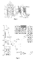
- PEMFCs are current generators whose operating principle, illustrated in figure 1 , is based on the conversion of chemical energy into electrical energy, by catalytic reaction of hydrogen and oxygen.
- Membrane-electrode assemblies or AMEs commonly referred to as battery cores, constitute the basic elements of PEMFCs. They are composed of two electrodes (anode and cathode, respectively) separated by a polymer membrane 2, said membrane 2 being in direct contact with the catalytic layer (3, 4, respectively) present on each electrode. Thus, the membrane 2 makes it possible to separate the anode and cathode compartments 5 6.
- the catalytic layers 3, 4 generally consist of platinum nano-particles (Pt) supported by carbon aggregates.
- Gaseous diffusion layers 7, 8 are placed on either side of the MEA 1 to ensure the electrical conduction, the homogeneous distribution of the reactive gases and the evacuation of the products.
- a system of channels 9, 10 placed on each side of the AME bring the reactive gases and evacuate the water and excess gases to the outside.
- the nanoparticles of the Pt x M y are alternative catalysts of interest with respect to the ORR reaction occurring at the PEMFC cathode ( Stamenkovic B. et al., SCIENCE, 315, 2007, 493 ; Stamenkovic B. et al., J. AM. CHEM. SOC., 128, 2006, 8813-8819 ).
- These bimetallic catalysts combining a second cheaper metal than platinum, thus reduce the overall cost of the catalyst.
- they have the particularity of increasing the production of hydrogen peroxide (H 2 O 2 ), a co-product of the reaction with water, during the operation of the PEMFCs.
- hydrogen peroxide is one of the chemical agents responsible for the degradation of the membrane 2 by a process called Fenton reaction. This comes from the dissociation of hydrogen peroxide into a radical and into an ion, catalyzed by the Fe 2+ or Fe 3+ metal ions generated by the corrosion of the bipolar plates: H 2 O 2 + Fe 2+ ⁇ Fe 3+ + HO • + OH - H 2 O 2 + Fe 3+ ⁇ Fe 2+ + HOO • + H + HOO • + Fe 3+ ⁇ Fe 2+ + O 2 + H + H 2 O 2 + HO • ⁇ H 2 O + HOO • HO • + Fe 2+ ⁇ Fe 3+ + OH -
- the principle of the invention is based on a theoretical analysis of the reaction mechanism of the formation of water and hydrogen peroxide on a model catalytic surface of Pt 3 Ni (111) (called "Pt-skeleton"), by means of of calculations using the theory of the functional density.
- Pt-skeleton a model catalytic surface of Pt 3 Ni (111) (called "Pt-skeleton"
- the corresponding scientific results show ( Figure 2 ), that the formation of hydrogen peroxide (H 2 O 2 ) on this well-structured bimetallic catalyst has a positive or endothermic overall thermodynamic barrier (associated with a high energy cost), in contrast to the formation of water which is exothermic (reduced energy cost).
- this bimetallic catalyst of the "Pt-skeleton" type is to significantly reduce the selectivity of hydrogen peroxide and this via its singular morphology having surface gaps in the second nickel metal, according to a regular network . It has also been observed that there are no active sites with respect to the ORR reaction within these gaps. Under these conditions, the formation of H 2 O 2 thus seems unlikely or at least greatly diminished.
- the present invention therefore relates to a completely original approach to protect the membrane and thus increase its life in a PEMFC battery. This is to mimic the particular catalytic structure described above, in order to reduce the formation of H 2 O 2 while preserving the activity towards the ORR (formation of water from oxygen and protons ).
- the support corresponds to the gas diffusion layer.
- a layer is typically made of carbon and typically has a thickness of the order of 200 micrometers.
- this layer is sensitive to heat and therefore potentially damaged by the temperatures imposed during the annealing.
- the deposition of the nanostructures is done on a support which is a heat resistant substrate, such as a silica layer. After annealing, the nanostructures must then be transferred to the gas diffusion layer. This transfer can be achieved by detaching the nanostructures of the first support with the aid of an electrolyte and then impregnating the gas diffusion layer with these nanostructures.
- the method according to the invention comprises an additional step of transferring, after annealing, the nanostructures on the gas diffusion layer.
- M represents a transition metal, advantageously chosen from nickel (Ni), iron (Fe), cobalt (Co) or chromium (Cr). M is of the same chemical nature in the two deposition steps (nanostructures then layer). However, a catalyst containing several transition metals of different nature is possible (multimetal material).
- Pt x M y x and y represent the stoichiometries of platinum and transition metal, respectively.
- the first step of the process therefore corresponds to the deposition on a support of nanostructures in Pt x M y .
- nanostructures structures of size less than 10 nanometers. In a particular case, they are nanoparticles of spherical shape defined by their diameter less than 10 nm. Alternatively, they may be rods whose largest dimension is less than 10 nm.
- this deposit is made by cathode sputtering (or ion beam sputtering or IBS).
- these nanostructures are formed by chemical synthesis, advantageously using precursors in the liquid phase and at low temperature.
- the Pt and M atoms are deposited on the substrate using a source of nano-aggregates to form nanostructures of Pt x M y , for example with an exposure time of 30 minutes.
- the next step is to anneal these nanostructures.
- the purpose of this step is to generate nanostructures with a morphology called "heart / shell". Concentrating the metal M on the core of the nanostructures makes it possible to increase the stability of the catalyst.
- the annealing temperature depends in particular on the size of the nanostructures but must not affect the integrity of the support. This is generally carried out at a temperature of between 600 ° C. and 1200 ° C., advantageously between 700 ° C. and 800 ° C.
- the annealing time is usually one hour.
- the next step is to deposit a Pt x M y layer, above or on the surface of the nanostructures obtained at the end of the first step. It is a question of obtaining a monolayer of homogeneous stoichiometry (" bulk-truncated layer ”) . In other words, it is to achieve a coating of these nanostructures using this layer.
- MOCVD Metal Organic Chemical Vapor Deposition
- platinum and cobalt deposition may be dimethyl (1,5-cyclooctadiene) platinum (II) [Pt II (Me 2 , cod), Strem] and cobalt (III) acetylacetonate [ Co III (acac) 3 , Strem], solubilized in toluene, with concentrations below 0.03M.
- the temperature of the deposition step by MOCVD depends in particular on the nature of the organometallic precursors in the presence, but is generally between 200 ° C. and 400 ° C., advantageously of the order of 300 ° C.
- this deposition can be carried out by cathodic sputtering (or in English " ion beam sputtering" or IBS)
- the final step is to chemically leach the metal M, so as to form gaps or cavities in the Pt x M y layer.
- This partial removal of the metal M may for example be carried out by immersion in a liquid electrolyte, especially in an acid such as sulfuric acid (H 2 SO 4 ), for example at a concentration of 0.1M for 1 hour.
- a liquid electrolyte especially in an acid such as sulfuric acid (H 2 SO 4 ), for example at a concentration of 0.1M for 1 hour.
- This chemical leaching of the metal M in the layer is advantageously controlled so as to produce structured voids or cavities, of size not exceeding 6 Angstroms. Indeed, larger cavities are likely to provide active sites vis-à-vis the production of hydrogen peroxide.
- the gaps formed at the end of the leaching step have a size of between 2 and 6 ⁇ .
- the invention provides a novel nanostructured catalyst which combines the advantages resulting from pure core / shell nanostructures into Pt x M y (offering greater ORR activity than pure Pt with good stability) and a layer of Pt x M y with gaps (reducing the production of H 2 O 2 ).
- the present invention provides a catalyst obtainable using the method described above, said catalyst comprising nanostructures core / shell Pt x M y covered with a layer of Pt x H there are gaps.
- these gaps or cavities are not through and therefore do not lead to the gas diffusion layer.
- their size advantageously does not exceed 5 to 6 Angstroms, with a size advantageously between 2 and 6 ⁇ .
- the leaching takes place directly on the cathode and / or the anode of the cell, before being mounted in the AME. This ensures the effectiveness and control of leaching.
- the present invention provides a method of improving the life of a PEMFC fuel cell comprising using as catalyst, at least at its cathode, an active material as described above. As demonstrated in the present application, the result is a reduction in H 2 O 2 production .
- the nanostructured Pt 3 Ni catalyst according to the invention makes it possible to reduce the production of H 2 O 2 by 50%. Furthermore, after 1000 hours of operation, the conductivity of the membrane is approximately doubled, which extends the life of the battery by about 500 hours (defined here as the time required for the potential of the cell to become no).
Landscapes
- Chemical & Material Sciences (AREA)
- Chemical Kinetics & Catalysis (AREA)
- General Chemical & Material Sciences (AREA)
- Electrochemistry (AREA)
- Engineering & Computer Science (AREA)
- Manufacturing & Machinery (AREA)
- Materials Engineering (AREA)
- Composite Materials (AREA)
- Physics & Mathematics (AREA)
- Thermal Sciences (AREA)
- Organic Chemistry (AREA)
- Inert Electrodes (AREA)
- Catalysts (AREA)
Description
- La présente invention se situe dans le domaine des piles à combustible à membrane échangeuse de protons (« Proton Exchange Membrane Fuel Cell » ou PEMFC).
- Elle propose une solution permettant de limiter la production de H2O2 lors de l'utilisation des catalyseurs bimétalliques de type PtxMy dans les cathodes de piles à combustible de type PEM, et ce grâce à l'élaboration d'un catalyseur nanostructuré selon l'invention.
- Les PEMFC sont des générateurs de courant dont le principe de fonctionnement, illustré à la
figure 1 , repose sur la conversion de l'énergie chimique en énergie électrique, par réaction catalytique de l'hydrogène et de l'oxygène. - Les assemblages membrane-électrodes ou AME 1, appelés communément coeurs de pile, constituent les éléments de base des PEMFC. Ils sont composés de deux électrodes (anode et cathode, respectivement) séparées par une membrane polymère 2, ladite membrane 2 étant en contact direct avec la couche catalytique (3, 4, respectivement) présentes sur chaque électrode. Ainsi, la membrane 2 permet de séparer les compartiments anodique 5 et cathodique 6.
- Les couches catalytiques 3, 4 sont généralement constituées de nano-particules de platine (Pt) supportées par des agrégats de carbone. Des couches de diffusion gazeuse 7, 8 (tissu de carbone, feutre...) sont disposées de part et d'autre de l'AME 1 pour assurer la conduction électrique, la répartition homogène des gaz réactifs et l'évacuation des produits. Un système de canaux 9, 10 placés de chaque côté de l'AME amènent les gaz réactifs et évacuent vers l'extérieur l'eau et les gaz en excès.
- A l'anode 3, l'oxydation de l'hydrogène sur le catalyseur produit des protons H+ et des électrons e-. Les protons traversent ensuite la membrane polymère 2 avant de réagir avec l'oxygène à la cathode 4. La réaction des protons avec l'oxygène (ORR pour l'acronyme anglo-saxon « Oxygen Redatction Reaction ») à la cathode conduit à la formation d'eau, d'un peu de peroxyde d'hydrogène (H2O2) et à la production de chaleur. L'amélioration de la durée de vie et la diminution des coûts des PEMFC constituent un enjeu majeur pour l'utilisation et le développement des piles pour le marché grand public. C'est pourquoi, la mise en évidence et la compréhension des phénomènes de vieillissement des coeurs de pile sont aujourd'hui essentielles.
- Les nanoparticules de type PtxMy, M étant un élément métallique de transition (par exemple Ni, Fe, Co, Cr), sont des catalyseurs alternatifs intéressants en ce qui concerne la réaction ORR se produisant à la cathode des PEMFC (Stamenkovic B. et al., SCIENCE, 315, 2007, 493 ; Stamenkovic B. et al., J. AM. CHEM. SOC., 128, 2006, 8813-8819). Ces catalyseurs bimétalliques, associant un second métal meilleur marché que le platine, permettent ainsi de réduire globalement le coût du catalyseur. En revanche, ils ont la particularité d'augmenter la production de peroxyde d'hydrogène (H2O2), co-produit de la réaction avec l'eau, pendant le fonctionnement des PEMFC.
- Or, le peroxyde d'hydrogène est l'un des agents chimiques responsables de la dégradation de la membrane 2 par un procédé appelé réaction de Fenton. Celle-ci provient de la dissociation du peroxyde d'hydrogène en un radical et en un ion, catalysée par les ions métalliques Fe2+ ou Fe3+ générés par la corrosion des plaques bipolaires :
H 2 O 2 + Fe 2+ → Fe 3+ + HO• + OH-
H 2 O 2 + Fe 3+ → Fe 2+ + HOO• + H +
HOO• + Fe 3+ → Fe 2+ + O 2 + H +
H2O2 + HO • → H2O + HOO•
HO• + Fe 2+ → Fe 3+ + OH-
- Le radical oxygène formé lors de la décomposition attaque le polymère conducteur protonique dégradant ainsi la membrane 2 via des réactions chimiques complexes (Romain Coulon et al. ECS Trans. 25 (35), 2010, 259-273)
- Le document HASCHE et al. (Journal of the Electrochemical Society, vol. 159, no. 1, 2011, pp B24-33) décrit un procédé de fabrication d'une couche catalytique pour PEMFC à base de nanoparticules de PtNi3, recuites puis soumises à lixiviation électrochimique.
- Le principe de l'invention repose sur une analyse théorique du mécanisme réactionnel de la formation de l'eau et du peroxyde d'hydrogène sur une surface catalytique modèle de Pt3Ni(111) (dite « Pt-skeleton »), au moyen de calculs utilisant la théorie de la fonctionnelle de la densité. Les résultats scientifiques correspondants montrent (
Figure 2 ), que la formation du peroxyde d'hydrogène (H2O2) sur ce catalyseur bimétallique bien structuré présente une barrière thermodynamique globale positive ou endothermique (associée à un coût énergétique important), au contraire de la formation de l'eau qui est exothermique (coût énergétique amoindri). En d'autres termes, la particularité de ce catalyseur bimétallique de type « Pt-skeleton » est de diminuer significativement la sélectivité en peroxyde d'hydrogène et cela via sa morphologie singulière présentant des lacunes en surface en second métal nickel, selon un réseau régulier. Il a également été observé qu'il n'y a pas de sites actifs vis-à-vis de la réaction ORR à l'intérieur de ces lacunes. Dans ces conditions, la formation de H2O2 semble donc improbable ou du moins fortement diminuée. - La présente invention a donc trait à une approche tout à fait originale pour protéger la membrane et ainsi augmenter sa durée de vie dans une pile PEMFC. Il s'agit ici de mimer la structure catalytique particulière décrite ci-dessus, afin de réduire la formation de H2O2 tout en préservant l'activité envers l'ORR (formation d'eau à partir de l'oxygène et des protons).
- Pour fabriquer un catalyseur ainsi nanostructuré, la combinaison de trois techniques différentes est nécessaire: un recuit suivi d'un dépôt MOCVD (« MetcrlloOrgarnic Chemical Vapor Deposition »), puis d'une lixiviation chimique (extraction du second métal en surface via l'électrolyte).
- En d'autres termes et selon un premier aspect, la présente invention concerne un procédé de fabrication d'un catalyseur pour PEMFC à base de PtxMy, comprenant les étapes suivantes :
- dépôt sur un support de nanostructures de PtxMy ;
- recuit des nanostructures ;
- dépôt d'une couche de PtxMy au-dessus des nanostructures ainsi formées ;
- lixiviation chimique du métal M.
- Dans un premier cas de figure, le support correspond à la couche de diffusion des gaz. De manière connue, une telle couche est typiquement en carbone et présente classiquement une épaisseur de l'ordre de 200 micromètres.
- Toutefois, il se peut que cette couche soit sensible à la chaleur et donc potentiellement endommagée par les températures imposées lors du recuit. Dans ce cas de figure, le dépôt des nanostructures se fait sur un support qui est un substrat résistant à la chaleur, tel qu'une couche de silice. Après recuit, les nanostructures doivent alors être transférées sur la couche de diffusion des gaz. Ce transfert peut être réalisé en détachant les nanostructures du premier support à l'aide d'un électrolyte, puis par imprégnation de la couche de diffusion des gaz par ces nanostructures.
- Ainsi et selon ce mode de réalisation particulier, le procédé selon l'invention comporte une étape supplémentaire consistant à transférer, après recuit, les nanostructures sur la couche de diffusion des gaz.
- Dans le cadre de l'invention, M représente un métal de transition, avantageusement choisi parmi le nickel (Ni), le fer (Fe), le cobalt (Co) ou le chrome (Cr). M est de même nature chimique aux deux étapes de dépôt (nanostructures puis couche). Toutefois, un catalyseur contenant plusieurs métaux de transition de nature différente est envisageable (matériau multimétallique).
- Dans la formule PtxMy, x et y représentent les stoechiométries du platine et du métal de transition, respectivement. Dans un mode de réalisation privilégié, PtxMy représente Pt3Ni, avec x = 3 et y = 1, respectivement.
- La première étape du procédé correspond donc au dépôt sur un support de nanostructures en PtxMy. Dans le cadre de l'invention, on entend par nanostructures, des structures de taille inférieure à 10 nanomètres. Dans un cas particulier, il s'agit de nanoparticules de forme sphérique, définies par leur diamètre inférieur à 10 nm. Alternativement, il peut s'agir de bâtonnets dont la plus grande dimension est inférieure à 10 nm.
- De manière avantageuse, ce dépôt est réalisé par pulvérisation cathodique (ou en anglais « ion beam sputtering » ou IBS). Alternativement, ces nanostructures sont formées par synthèse chimique, avantageusement à l'aide de précurseurs en phase liquide et à basse température.
- En pratique, les atomes de Pt et M sont déposés sur le substrat en utilisant une source de nano-agrégats pour former des nanostructures de PtxMy, par exemple avec un temps d'exposition de 30 minutes.
- L'étape suivante consiste à réaliser un recuit de ces nanostructures. Le but de cette étape est de générer des nanostructures présentant une morphologie dite « coeur/coquille ». Le fait de concentrer le métal M sur le noyau des nanostructures permet d'augmenter la stabilité du catalyseur.
- La température du recuit dépend notamment de la taille des nanostructures mais ne doit pas affecter l'intégrité du support. Celui-ci est généralement réalisé à une température comprise entre 600°C et 1200°C, avantageusement comprise entre 700 °C et 800 °C. La durée du recuit est généralement d'une heure.
- L'étape suivante consiste à déposer une couche en PtxMy, au-dessus ou à la surface des nanostructures obtenues à l'issue de la première étape. Il s'agit d'obtenir une monocouche de stoechiométrie homogène (« bulk-truncarted layer »). En d'autres termes, il s'agit de réaliser un enrobage de ces nanostructures à l'aide de cette couche.
- Une technique particulièrement adaptée pour ce dépôt est la technique MOCVD (acronyme anglo-saxon pour « MetalloOrganic Chemical Vapor Deposition »). Cette technique nécessite la mise en oeuvre de précurseurs organométalliques adaptés. Par exemple, les précurseurs pour un dépôt de platine et cobalt peuvent être du diméthyl(1,5-cyclooctadiène) platinum(II) [PtII(Me2,cod), Strem] et de l'acétylacétonate de cobalt(III) [CoIII(acac)3, Strem], solubilisés dans le toluène, avec des concentrations inférieures à 0,03 M.
- La température de l'étape de dépôt par MOCVD dépend notamment de la nature des précurseurs organométalliques en présence, mais est généralement comprise entre 200 °C et 400 °C, avantageusement de l'ordre de 300 °C.
- Alternativement et comme dans la première étape relative au dépôt des nanostructures, ce dépôt peut être réalisé par pulvérisation cathodique (ou en anglais « ion beam sputtering » ou IBS)
- L'étape finale consiste à réaliser une lixiviation chimique du métal M, de sorte à former des lacunes ou cavités dans la couche de PtxMy.
- Cette élimination partielle du métal M peut par exemple être réalisée par immersion dans un électrolyte liquide, notamment dans un acide tel que l'acide sulfurique (H2SO4), par exemple à une concentration 0.1M pendant 1 heure.
- Cette lixiviation chimique du métal M dans la couche est avantageusement contrôlée de manière à produire des lacunes ou cavités structurées, de taille n'excédant pas 6 Angströms. En effet, des cavités plus grosses sont susceptibles de fournir des sites actifs vis-à-vis de la production de peroxyde d'hydrogène.
- De manière privilégiée, les lacunes formées à l'issue de l'étape de lixiviation présente une taille comprise entre 2 et 6Å.
- Selon un autre aspect de l'invention, celle-ci offre un nouveau catalyseur nanostructuré qui combine les avantages résultant des nanostructures coeur/coquille pures en PtxMy (offrant une activité ORR supérieure à celle du Pt pur avec une bonne stabilité) et une couche de PtxMy avec des lacunes (réduisant la production de H2O2).
- En d'autres termes, la présente invention propose un catalyseur susceptible d'être obtenu à l'aide du procédé décrit ci-dessus, ledit catalyseur comprenant des nanostructures coeur/coquille en PtxMy recouvertes d'une couche de PtxMy présentant des lacunes.
- Dans le cadre de l'invention, ces lacunes ou cavités ne sont pas traversantes et ne débouchent donc pas sur la couche de diffusion des gaz. En outre et comme déjà dit, leur taille (assimilable ici à leur diamètre) ne dépasse avantageusement pas les 5 à 6 Angströms, avec une taille avantageusement comprise entre 2 et 6Å.
- Comme déjà dit, un tel catalyseur présente tout son intérêt dans le cadre de piles à combustible de type PEMFC, en particulier au niveau de la cathode de telles piles. Toutefois, il est envisageable de prévoir une pile dotée d'un catalyseur selon l'invention à la fois à la cathode et à l'anode.
- De manière notoire, la lixiviation se déroule directement sur la cathode et/ou l'anode de la pile, avant son montage dans l'AME. Ceci permet d'assurer l'efficacité et le contrôle de la lixiviation.
- Ainsi, la présente invention offre un procédé d'amélioration de la durée de vie d'une pile à combustible de type PEMFC consistant à utiliser comme catalyseur, au moins au niveau de sa cathode, un matériau actif tel que décrit précédemment. Comme démontré dans le cadre de la présente demande, il en résulte une réduction de la production de H2O2.
- La manière dont l'invention peut être réalisée et les avantages qui en découlent ressortiront mieux de l'exemple de réalisation qui suit, donné à titre indicatif et non limitatif, à l'appui des figures annexées parmi lesquelles :
- La
figure 1 représente le schéma du principe de fonctionnement d'une pile à combustible de type PEMFC. - La
figure 2 représente le profil d'énergie thermodynamique pour la formation de H2O et H2O2 sur une surface Pt3Ni(111) de type « Pt-skeleton » établi à partir de calculs utilisant la théorie de la fonctionnelle de la densité en conditions périodiques. S5 représente l'étape de formation de l'hydroperoxyl (OOH) qui est l'espèce de surface précurseur pour la formation du peroxyde d'hydrogène H2O2. - La
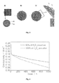
figure 3 représente les différentes étapes mises en oeuvre pour la fabrication d'un catalyseur nanostructuré selon l'invention : A/ recuit ; B/ dépôt de la couche de Pt3M grâce à la technique MOCVD ; C/ lixiviation chimique du métal M. - La
figure 4 représente l'évolution de la conductivité de la membrane en fonction du temps pour 2 taux différents de production de H2O2 (100% et 50%, respectivement). - Des expériences comparatives ont été menées dans une pile PEMFC contenant soit :
- une membrane en présence d'une cathode avec une structure coeur/coquille en Pt3Ni,
- ou, une membrane en présence d'une cathode avec un catalyseur Pt3Ni nanostructuré selon l'invention, en particulier selon le procédé illustré à la
figure 3 . - Les résultats sont présentés à la
figure 4 . - Dans le premier cas, la membrane a une durabilité (perte de conductivité protonique de 80%) d'environ 1000 heures dans des conditions OCV (« Open Circuit Voltage »: température = 80°C ; humidité relative de l'anode et de la cathode = 80% ; pression de l'anode et de la cathode : 1.5 bar; chargement de PtNi : 0.3 mg.cm-2 dans l'anode et 0.6 mg.cm-2 dans la cathode ; épaisseur de la membrane : 25 µm ; surface active : 25 cm2).
- Dans les mêmes conditions, le catalyseur Pt3Ni nanostructuré selon l'invention permet de diminuer de 50% la production de H2O2. Par ailleurs, après 1000 heures de fonctionnement, la conductivité de la membrane est à peu près doublée, ce qui prolonge d'environ 500 heures la durée de vie de la pile (définie ici comme le temps nécessaire pour que le potentiel de la cellule devienne nul).
Claims (15)
- Procédé de fabrication d'un catalyseur (3, 4) pour pile à combustible à membrane échangeuse de protons PEMFC, le dit catalyseur étant à base de PtxMy, M étant un métal de transition, le dit procédé comprenant les étapes suivantes :- dépôt sur un support de nanostructures en PtxMy ;- recuit des nanostructures ;- dépôt d'une couche de PtxMy à la surface des nanostructures ainsi formées ;- lixiviation chimique du métal M.
- Procédé de fabrication d'un catalyseur (3, 4) pour PEMFC selon la revendication 1, caractérisé en ce que le support est la couche de diffusion des gaz, avantageusement d'une épaisseur de 200 micromètres.
- Procédé de fabrication d'un catalyseur (3, 4) pour PEMFC selon la revendication 1, caractérisé en ce que le support n'est pas la couche de diffusion des gaz et qu'après recuit, les nanostructures sont transférées sur la couche de diffusion des gaz.
- Procédé de fabrication d'un catalyseur (3, 4) pour PEMFC selon l'une des revendications précédentes, caractérisé en ce que le métal M est choisi dans le groupe constitué de Ni, Fe, Co et Cr.
- Procédé de fabrication d'un catalyseur (3, 4) pour PEMFC selon la revendication 4, caractérisé en ce que le catalyseur est réalisé avec du Pt3Ni.
- Procédé de fabrication d'un catalyseur (3, 4) pour PEMFC selon l'une des revendications précédentes, caractérisé en ce que le dépôt des nanostructures est réalisé par pulvérisation cathodique.
- Procédé de fabrication d'un catalyseur (3, 4) pour PEMFC selon l'une des revendications précédentes, caractérisé en ce que le recuit est réalisé à une température comprise entre 600 °C et 1200 °C, avantageusement pendant une durée de 1 heure.
- Procédé de fabrication d'un catalyseur (3, 4) pour PEMFC selon l'une des revendications précédentes, caractérisé en ce que le dépôt de la couche de PtxMy est réalisé par MOCVD.
- Procédé de fabrication d'un catalyseur (3, 4) pour PEMFC selon la revendication 8, caractérisé en ce que le dépôt par MOCVD est réalisé à l'aide de précurseurs organométalliques du platine et du métal, avantageusement à une température comprise entre 200 °C et 400 °C, par exemple à 300 °C.
- Procédé de fabrication d'un catalyseur (3, 4) pour PEMFC selon l'une des revendications précédentes, caractérisé en ce que la lixiviation chimique du métal M est réalisée par immersion dans un électrolyte liquide, par exemple dans du H2SO4, avantageusement pendant 1 heure.
- Catalyseur susceptible d'être obtenu à l'aide du procédé selon l'une des revendications 1 à 10, ledit catalyseur comprenant des nanostructures coeur/coquille en PtxMy recouvertes d'une couche de PtxMy présentant des lacunes.
- Catalyseur selon la revendication 11, caractérisé en ce que les lacunes ont une taille n'excédant pas 6 Angstrôms, avantageusement comprise entre 2 et 6Å.
- Pile à combustible de type PEMFC comprenant au moins au niveau de l'une de ses électrodes, avantageusement la cathode (4), un catalyseur selon la revendication 11 ou 12.
- Utilisation d'un catalyseur selon la revendication 11 ou 12 pour réduire la production en H2O2 d'une pile à combustible de type PEMFC.
- Utilisation d'un catalyseur selon la revendication 11 ou 12 pour améliorer la durée de vie d'une pile à combustible de type PEMFC.
Applications Claiming Priority (2)
| Application Number | Priority Date | Filing Date | Title |
|---|---|---|---|
| FR1157015A FR2978683B1 (fr) | 2011-08-01 | 2011-08-01 | Catalyseur nanostructure en ptxmy pour piles pemfc a haute activite et a production moderee de h2o2 |
| PCT/FR2012/051723 WO2013017772A1 (fr) | 2011-08-01 | 2012-07-20 | Catalyseur nanostructure en ptxmy pour piles pemfc a haute activite et a production moderee de h2o2 |
Publications (2)
| Publication Number | Publication Date |
|---|---|
| EP2751860A1 EP2751860A1 (fr) | 2014-07-09 |
| EP2751860B1 true EP2751860B1 (fr) | 2015-03-04 |
Family
ID=46724495
Family Applications (1)
| Application Number | Title | Priority Date | Filing Date |
|---|---|---|---|
| EP12750430.6A Not-in-force EP2751860B1 (fr) | 2011-08-01 | 2012-07-20 | Catalyseur nanostructuré en ptxmy pour piles à combustible pem à haute activité et à production modérée de h2o2 |
Country Status (8)
| Country | Link |
|---|---|
| US (1) | US9608276B2 (fr) |
| EP (1) | EP2751860B1 (fr) |
| JP (1) | JP6049717B2 (fr) |
| KR (1) | KR20140053139A (fr) |
| CN (1) | CN103891021A (fr) |
| BR (1) | BR112014002193A2 (fr) |
| FR (1) | FR2978683B1 (fr) |
| WO (1) | WO2013017772A1 (fr) |
Families Citing this family (5)
| Publication number | Priority date | Publication date | Assignee | Title |
|---|---|---|---|---|
| KR102391251B1 (ko) * | 2015-08-10 | 2022-04-26 | 삼성에스디아이 주식회사 | 연료 전지용 촉매, 이의 제조 방법 및 이를 포함하는 전극, 막-전극 어셈블리 및 연료 전지 시스템 |
| CN106582713B (zh) * | 2016-12-13 | 2019-07-16 | 扬州大学 | 一种Pt3Ni@PtNi2核壳结构纳米线的制备方法 |
| GB201903950D0 (en) | 2019-03-22 | 2019-05-08 | Johnson Matthey Fuel Cells Ltd | Catalyst |
| JP7377693B2 (ja) * | 2019-12-13 | 2023-11-10 | トヨタ紡織株式会社 | 担持体の製造方法 |
| EP4184618A1 (fr) * | 2021-11-17 | 2023-05-24 | Leibniz-Institut für Plasmaforschung und Technologie e.V. | Procédé de formation d'une membrane catalytiquement active ou d'un ensemble membrane-électrode |
Family Cites Families (18)
| Publication number | Priority date | Publication date | Assignee | Title |
|---|---|---|---|---|
| US4366041A (en) * | 1981-02-18 | 1982-12-28 | Ppg Industries, Inc. | Method of preparing a cathode-diaphragm unit |
| JPH06246160A (ja) * | 1993-02-22 | 1994-09-06 | Tanaka Kikinzoku Kogyo Kk | 燃料電池用合金触媒の製造方法 |
| JP3874380B2 (ja) * | 1996-08-26 | 2007-01-31 | エヌ・イーケムキャット株式会社 | 空格子点型格子欠陥を有するカーボン担持白金スケルトン合金電極触媒 |
| CN1194434C (zh) * | 2002-12-17 | 2005-03-23 | 武汉理工大学 | 质子交换膜电解质燃料电池碳载铂铁合金电催化剂及其制备方法 |
| JP5082187B2 (ja) * | 2003-10-06 | 2012-11-28 | 日産自動車株式会社 | 固体高分子型燃料電池用電極触媒粒子の製造方法 |
| US20050251245A1 (en) * | 2004-05-05 | 2005-11-10 | Karl Sieradzki | Methods and apparatus with porous materials |
| US7811965B2 (en) * | 2004-08-18 | 2010-10-12 | Symyx Solutions, Inc. | Platinum-copper-nickel fuel cell catalyst |
| JP4758789B2 (ja) * | 2005-03-09 | 2011-08-31 | 三星エスディアイ株式会社 | 電極用担持触媒とその製造方法,プロトン交換膜燃料電池用電極およびプロトン交換膜燃料電池 |
| US20080020923A1 (en) * | 2005-09-13 | 2008-01-24 | Debe Mark K | Multilayered nanostructured films |
| US20070082814A1 (en) * | 2005-10-12 | 2007-04-12 | 3M Innovative Properties Company | Ternary nanocatalyst and method of making |
| JPWO2007119640A1 (ja) * | 2006-03-31 | 2009-08-27 | トヨタ自動車株式会社 | 燃料電池用電極触媒及びその製造方法 |
| US8288308B2 (en) * | 2006-08-30 | 2012-10-16 | Umicore Ag & Co. Kg | Core/shell-type catalyst particles and methods for their preparation |
| BRPI0716116A2 (pt) * | 2006-08-30 | 2013-10-01 | Umicore Ag & Co Kg | partÍculas catalÍticas tipo nécleo/casca e mÉtodos para sua preparaÇço |
| US7994089B2 (en) * | 2007-09-07 | 2011-08-09 | University Of Houston System | De-alloyed platinum nanoparticles |
| JP2010027364A (ja) * | 2008-07-18 | 2010-02-04 | Nissan Motor Co Ltd | 燃料電池用電極触媒およびその製造方法 |
| US20100216632A1 (en) * | 2009-02-25 | 2010-08-26 | Brookhaven Science Associates, Llc | High Stability, Self-Protecting Electrocatalyst Particles |
| JP2012035178A (ja) * | 2010-08-05 | 2012-02-23 | Toyota Motor Corp | 触媒の製造方法及び触媒 |
| DE102010044288A1 (de) * | 2010-09-03 | 2012-03-08 | Elcomax Gmbh | Verfahren zur Herstellung von Platin-Übergangsmetall-Katalysatorpartikeln |
-
2011
- 2011-08-01 FR FR1157015A patent/FR2978683B1/fr not_active Expired - Fee Related
-
2012
- 2012-07-20 KR KR1020147002316A patent/KR20140053139A/ko not_active Withdrawn
- 2012-07-20 JP JP2014523360A patent/JP6049717B2/ja not_active Expired - Fee Related
- 2012-07-20 WO PCT/FR2012/051723 patent/WO2013017772A1/fr not_active Ceased
- 2012-07-20 BR BR112014002193A patent/BR112014002193A2/pt not_active IP Right Cessation
- 2012-07-20 EP EP12750430.6A patent/EP2751860B1/fr not_active Not-in-force
- 2012-07-20 CN CN201280037213.0A patent/CN103891021A/zh active Pending
-
2014
- 2014-01-23 US US14/162,032 patent/US9608276B2/en not_active Expired - Fee Related
Also Published As
| Publication number | Publication date |
|---|---|
| KR20140053139A (ko) | 2014-05-07 |
| EP2751860A1 (fr) | 2014-07-09 |
| FR2978683A1 (fr) | 2013-02-08 |
| FR2978683B1 (fr) | 2016-02-26 |
| US20140186744A1 (en) | 2014-07-03 |
| BR112014002193A2 (pt) | 2017-02-21 |
| JP2014522085A (ja) | 2014-08-28 |
| CN103891021A (zh) | 2014-06-25 |
| JP6049717B2 (ja) | 2016-12-21 |
| US9608276B2 (en) | 2017-03-28 |
| WO2013017772A1 (fr) | 2013-02-07 |
Similar Documents
| Publication | Publication Date | Title |
|---|---|---|
| JP5005015B2 (ja) | 燃料電池用電極、これを含む燃料電池システム及び燃料電池用電極の製造方法 | |
| US20060115711A1 (en) | Electrode for fuel cell, fuel cell comprising the same, and method for preparing the same | |
| CA2767793C (fr) | Alliages de platine et de palladium utilisables en tant qu'electrodes de pile a combustible | |
| WO2006088194A1 (fr) | Catalyseur d’électrode et son procédé de fabrication | |
| FR2916906A1 (fr) | Membrane echangeuse protonique et cellule comportant une telle membrane | |
| CA2647507A1 (fr) | Catalyseur d'electrodes pour pile a combustible et procede de fabrication du catalyseur | |
| WO2013017772A1 (fr) | Catalyseur nanostructure en ptxmy pour piles pemfc a haute activite et a production moderee de h2o2 | |
| US9343749B2 (en) | Ultrathin platinum films | |
| EP2559085B1 (fr) | Structuration d'électrode de piles à combustible à membrane échangeuse de protons | |
| KR20100127577A (ko) | 그라핀이 코팅된 연료전지용 분리판 및 이의 제조방법 | |
| CN111342068B (zh) | 夹层式催化剂及其制备方法和应用 | |
| WO2009118991A1 (fr) | Séparateur de pile à combustible | |
| US20070202392A1 (en) | Electrocatalyst compositions for use in an electrochemical fuel cell and methods of making the same | |
| JP7748066B2 (ja) | 電気化学セル用触媒及びその製造方法 | |
| Jung et al. | Effect of the fabrication condition of membrane electrode assemblies with carbon-supported ordered PtCo electrocatalyst on the durability of polymer electrolyte membrane fuel cells | |
| WO2014001510A1 (fr) | Procédé de fabrication d'un assemblage electrode/membrane échangeuse de protons | |
| Wan et al. | Enhancing the CO tolerance of PEMFC MEAs by combining sputter-deposited and direct-printed composite anode catalyst layers | |
| Xu et al. | Enhancing Oxygen Reduction Reaction Performance in Dealloyed Multicomponent Alloy Catalysts in Zn‐and Al‐Air Batteries: Strategic Lowers O‐to‐OH Energy Barriers | |
| FR2959610A1 (fr) | Procede de depot d'une couche catalytique pour pile a combustible | |
| JP2005353376A (ja) | 固体高分子形燃料電池用の電極の製造方法 | |
| Cho et al. | Mass‐Transport–Engineered CCM Architecture Employing MPL‐Free Carbon Paper and Graphene‐Coated Ni Foam Channels for High‐Temperature PEM Fuel Cells | |
| EP2480706B1 (fr) | Procédé de dépôt d'un métal sur une couche en carbone poreux | |
| DE102016013185A1 (de) | Verfahren zur Herstellung von katalytischen Schichten für elektrochemische Systeme | |
| EP3570353A1 (fr) | Couches catalytiques comprenant un fullerene | |
| JP2005259505A (ja) | 燃料電池用電極の製造方法 |
Legal Events
| Date | Code | Title | Description |
|---|---|---|---|
| PUAI | Public reference made under article 153(3) epc to a published international application that has entered the european phase |
Free format text: ORIGINAL CODE: 0009012 |
|
| 17P | Request for examination filed |
Effective date: 20140205 |
|
| AK | Designated contracting states |
Kind code of ref document: A1 Designated state(s): AL AT BE BG CH CY CZ DE DK EE ES FI FR GB GR HR HU IE IS IT LI LT LU LV MC MK MT NL NO PL PT RO RS SE SI SK SM TR |
|
| DAX | Request for extension of the european patent (deleted) | ||
| GRAP | Despatch of communication of intention to grant a patent |
Free format text: ORIGINAL CODE: EPIDOSNIGR1 |
|
| RIC1 | Information provided on ipc code assigned before grant |
Ipc: H01M 4/92 20060101AFI20141126BHEP Ipc: H01M 4/88 20060101ALI20141126BHEP Ipc: H01M 4/86 20060101ALI20141126BHEP Ipc: H01M 8/10 20060101ALN20141126BHEP |
|
| INTG | Intention to grant announced |
Effective date: 20141215 |
|
| GRAS | Grant fee paid |
Free format text: ORIGINAL CODE: EPIDOSNIGR3 |
|
| GRAA | (expected) grant |
Free format text: ORIGINAL CODE: 0009210 |
|
| AK | Designated contracting states |
Kind code of ref document: B1 Designated state(s): AL AT BE BG CH CY CZ DE DK EE ES FI FR GB GR HR HU IE IS IT LI LT LU LV MC MK MT NL NO PL PT RO RS SE SI SK SM TR |
|
| REG | Reference to a national code |
Ref country code: GB Ref legal event code: FG4D Free format text: NOT ENGLISH |
|
| REG | Reference to a national code |
Ref country code: CH Ref legal event code: EP |
|
| REG | Reference to a national code |
Ref country code: IE Ref legal event code: FG4D Free format text: LANGUAGE OF EP DOCUMENT: FRENCH |
|
| REG | Reference to a national code |
Ref country code: AT Ref legal event code: REF Ref document number: 714546 Country of ref document: AT Kind code of ref document: T Effective date: 20150415 |
|
| REG | Reference to a national code |
Ref country code: DE Ref legal event code: R096 Ref document number: 602012005706 Country of ref document: DE Effective date: 20150416 |
|
| REG | Reference to a national code |
Ref country code: AT Ref legal event code: MK05 Ref document number: 714546 Country of ref document: AT Kind code of ref document: T Effective date: 20150304 Ref country code: NL Ref legal event code: VDEP Effective date: 20150304 |
|
| PG25 | Lapsed in a contracting state [announced via postgrant information from national office to epo] |
Ref country code: FI Free format text: LAPSE BECAUSE OF FAILURE TO SUBMIT A TRANSLATION OF THE DESCRIPTION OR TO PAY THE FEE WITHIN THE PRESCRIBED TIME-LIMIT Effective date: 20150304 Ref country code: LT Free format text: LAPSE BECAUSE OF FAILURE TO SUBMIT A TRANSLATION OF THE DESCRIPTION OR TO PAY THE FEE WITHIN THE PRESCRIBED TIME-LIMIT Effective date: 20150304 Ref country code: HR Free format text: LAPSE BECAUSE OF FAILURE TO SUBMIT A TRANSLATION OF THE DESCRIPTION OR TO PAY THE FEE WITHIN THE PRESCRIBED TIME-LIMIT Effective date: 20150304 Ref country code: NO Free format text: LAPSE BECAUSE OF FAILURE TO SUBMIT A TRANSLATION OF THE DESCRIPTION OR TO PAY THE FEE WITHIN THE PRESCRIBED TIME-LIMIT Effective date: 20150604 Ref country code: SE Free format text: LAPSE BECAUSE OF FAILURE TO SUBMIT A TRANSLATION OF THE DESCRIPTION OR TO PAY THE FEE WITHIN THE PRESCRIBED TIME-LIMIT Effective date: 20150304 Ref country code: ES Free format text: LAPSE BECAUSE OF FAILURE TO SUBMIT A TRANSLATION OF THE DESCRIPTION OR TO PAY THE FEE WITHIN THE PRESCRIBED TIME-LIMIT Effective date: 20150304 |
|
| REG | Reference to a national code |
Ref country code: LT Ref legal event code: MG4D |
|
| PG25 | Lapsed in a contracting state [announced via postgrant information from national office to epo] |
Ref country code: RS Free format text: LAPSE BECAUSE OF FAILURE TO SUBMIT A TRANSLATION OF THE DESCRIPTION OR TO PAY THE FEE WITHIN THE PRESCRIBED TIME-LIMIT Effective date: 20150304 Ref country code: GR Free format text: LAPSE BECAUSE OF FAILURE TO SUBMIT A TRANSLATION OF THE DESCRIPTION OR TO PAY THE FEE WITHIN THE PRESCRIBED TIME-LIMIT Effective date: 20150605 Ref country code: AT Free format text: LAPSE BECAUSE OF FAILURE TO SUBMIT A TRANSLATION OF THE DESCRIPTION OR TO PAY THE FEE WITHIN THE PRESCRIBED TIME-LIMIT Effective date: 20150304 Ref country code: LV Free format text: LAPSE BECAUSE OF FAILURE TO SUBMIT A TRANSLATION OF THE DESCRIPTION OR TO PAY THE FEE WITHIN THE PRESCRIBED TIME-LIMIT Effective date: 20150304 |
|
| PG25 | Lapsed in a contracting state [announced via postgrant information from national office to epo] |
Ref country code: NL Free format text: LAPSE BECAUSE OF FAILURE TO SUBMIT A TRANSLATION OF THE DESCRIPTION OR TO PAY THE FEE WITHIN THE PRESCRIBED TIME-LIMIT Effective date: 20150304 |
|
| PG25 | Lapsed in a contracting state [announced via postgrant information from national office to epo] |
Ref country code: EE Free format text: LAPSE BECAUSE OF FAILURE TO SUBMIT A TRANSLATION OF THE DESCRIPTION OR TO PAY THE FEE WITHIN THE PRESCRIBED TIME-LIMIT Effective date: 20150304 Ref country code: PT Free format text: LAPSE BECAUSE OF FAILURE TO SUBMIT A TRANSLATION OF THE DESCRIPTION OR TO PAY THE FEE WITHIN THE PRESCRIBED TIME-LIMIT Effective date: 20150706 Ref country code: SK Free format text: LAPSE BECAUSE OF FAILURE TO SUBMIT A TRANSLATION OF THE DESCRIPTION OR TO PAY THE FEE WITHIN THE PRESCRIBED TIME-LIMIT Effective date: 20150304 Ref country code: RO Free format text: LAPSE BECAUSE OF FAILURE TO SUBMIT A TRANSLATION OF THE DESCRIPTION OR TO PAY THE FEE WITHIN THE PRESCRIBED TIME-LIMIT Effective date: 20150304 Ref country code: CZ Free format text: LAPSE BECAUSE OF FAILURE TO SUBMIT A TRANSLATION OF THE DESCRIPTION OR TO PAY THE FEE WITHIN THE PRESCRIBED TIME-LIMIT Effective date: 20150304 |
|
| PG25 | Lapsed in a contracting state [announced via postgrant information from national office to epo] |
Ref country code: PL Free format text: LAPSE BECAUSE OF FAILURE TO SUBMIT A TRANSLATION OF THE DESCRIPTION OR TO PAY THE FEE WITHIN THE PRESCRIBED TIME-LIMIT Effective date: 20150304 Ref country code: IS Free format text: LAPSE BECAUSE OF FAILURE TO SUBMIT A TRANSLATION OF THE DESCRIPTION OR TO PAY THE FEE WITHIN THE PRESCRIBED TIME-LIMIT Effective date: 20150704 |
|
| REG | Reference to a national code |
Ref country code: DE Ref legal event code: R097 Ref document number: 602012005706 Country of ref document: DE |
|
| PG25 | Lapsed in a contracting state [announced via postgrant information from national office to epo] |
Ref country code: IT Free format text: LAPSE BECAUSE OF FAILURE TO SUBMIT A TRANSLATION OF THE DESCRIPTION OR TO PAY THE FEE WITHIN THE PRESCRIBED TIME-LIMIT Effective date: 20150304 |
|
| PLBE | No opposition filed within time limit |
Free format text: ORIGINAL CODE: 0009261 |
|
| STAA | Information on the status of an ep patent application or granted ep patent |
Free format text: STATUS: NO OPPOSITION FILED WITHIN TIME LIMIT |
|
| PG25 | Lapsed in a contracting state [announced via postgrant information from national office to epo] |
Ref country code: DK Free format text: LAPSE BECAUSE OF FAILURE TO SUBMIT A TRANSLATION OF THE DESCRIPTION OR TO PAY THE FEE WITHIN THE PRESCRIBED TIME-LIMIT Effective date: 20150304 |
|
| 26N | No opposition filed |
Effective date: 20151207 |
|
| PG25 | Lapsed in a contracting state [announced via postgrant information from national office to epo] |
Ref country code: SI Free format text: LAPSE BECAUSE OF FAILURE TO SUBMIT A TRANSLATION OF THE DESCRIPTION OR TO PAY THE FEE WITHIN THE PRESCRIBED TIME-LIMIT Effective date: 20150304 Ref country code: MC Free format text: LAPSE BECAUSE OF FAILURE TO SUBMIT A TRANSLATION OF THE DESCRIPTION OR TO PAY THE FEE WITHIN THE PRESCRIBED TIME-LIMIT Effective date: 20150304 |
|
| REG | Reference to a national code |
Ref country code: CH Ref legal event code: PL |
|
| PG25 | Lapsed in a contracting state [announced via postgrant information from national office to epo] |
Ref country code: LU Free format text: LAPSE BECAUSE OF FAILURE TO SUBMIT A TRANSLATION OF THE DESCRIPTION OR TO PAY THE FEE WITHIN THE PRESCRIBED TIME-LIMIT Effective date: 20150720 |
|
| REG | Reference to a national code |
Ref country code: IE Ref legal event code: MM4A |
|
| PG25 | Lapsed in a contracting state [announced via postgrant information from national office to epo] |
Ref country code: LI Free format text: LAPSE BECAUSE OF NON-PAYMENT OF DUE FEES Effective date: 20150731 Ref country code: CH Free format text: LAPSE BECAUSE OF NON-PAYMENT OF DUE FEES Effective date: 20150731 |
|
| PG25 | Lapsed in a contracting state [announced via postgrant information from national office to epo] |
Ref country code: IE Free format text: LAPSE BECAUSE OF NON-PAYMENT OF DUE FEES Effective date: 20150720 |
|
| REG | Reference to a national code |
Ref country code: FR Ref legal event code: PLFP Year of fee payment: 5 |
|
| PGFP | Annual fee paid to national office [announced via postgrant information from national office to epo] |
Ref country code: GB Payment date: 20160719 Year of fee payment: 5 Ref country code: DE Payment date: 20160719 Year of fee payment: 5 |
|
| PGFP | Annual fee paid to national office [announced via postgrant information from national office to epo] |
Ref country code: FR Payment date: 20160729 Year of fee payment: 5 |
|
| PG25 | Lapsed in a contracting state [announced via postgrant information from national office to epo] |
Ref country code: MT Free format text: LAPSE BECAUSE OF FAILURE TO SUBMIT A TRANSLATION OF THE DESCRIPTION OR TO PAY THE FEE WITHIN THE PRESCRIBED TIME-LIMIT Effective date: 20150304 |
|
| PG25 | Lapsed in a contracting state [announced via postgrant information from national office to epo] |
Ref country code: HU Free format text: LAPSE BECAUSE OF FAILURE TO SUBMIT A TRANSLATION OF THE DESCRIPTION OR TO PAY THE FEE WITHIN THE PRESCRIBED TIME-LIMIT; INVALID AB INITIO Effective date: 20120720 Ref country code: SM Free format text: LAPSE BECAUSE OF FAILURE TO SUBMIT A TRANSLATION OF THE DESCRIPTION OR TO PAY THE FEE WITHIN THE PRESCRIBED TIME-LIMIT Effective date: 20150304 Ref country code: BG Free format text: LAPSE BECAUSE OF FAILURE TO SUBMIT A TRANSLATION OF THE DESCRIPTION OR TO PAY THE FEE WITHIN THE PRESCRIBED TIME-LIMIT Effective date: 20150304 |
|
| PG25 | Lapsed in a contracting state [announced via postgrant information from national office to epo] |
Ref country code: CY Free format text: LAPSE BECAUSE OF FAILURE TO SUBMIT A TRANSLATION OF THE DESCRIPTION OR TO PAY THE FEE WITHIN THE PRESCRIBED TIME-LIMIT Effective date: 20150304 |
|
| PG25 | Lapsed in a contracting state [announced via postgrant information from national office to epo] |
Ref country code: BE Free format text: LAPSE BECAUSE OF NON-PAYMENT OF DUE FEES Effective date: 20150731 |
|
| REG | Reference to a national code |
Ref country code: DE Ref legal event code: R119 Ref document number: 602012005706 Country of ref document: DE |
|
| GBPC | Gb: european patent ceased through non-payment of renewal fee |
Effective date: 20170720 |
|
| REG | Reference to a national code |
Ref country code: FR Ref legal event code: ST Effective date: 20180330 |
|
| PG25 | Lapsed in a contracting state [announced via postgrant information from national office to epo] |
Ref country code: GB Free format text: LAPSE BECAUSE OF NON-PAYMENT OF DUE FEES Effective date: 20170720 Ref country code: DE Free format text: LAPSE BECAUSE OF NON-PAYMENT OF DUE FEES Effective date: 20180201 |
|
| PG25 | Lapsed in a contracting state [announced via postgrant information from national office to epo] |
Ref country code: FR Free format text: LAPSE BECAUSE OF NON-PAYMENT OF DUE FEES Effective date: 20170731 |
|
| PG25 | Lapsed in a contracting state [announced via postgrant information from national office to epo] |
Ref country code: MK Free format text: LAPSE BECAUSE OF FAILURE TO SUBMIT A TRANSLATION OF THE DESCRIPTION OR TO PAY THE FEE WITHIN THE PRESCRIBED TIME-LIMIT Effective date: 20150304 Ref country code: TR Free format text: LAPSE BECAUSE OF FAILURE TO SUBMIT A TRANSLATION OF THE DESCRIPTION OR TO PAY THE FEE WITHIN THE PRESCRIBED TIME-LIMIT Effective date: 20150304 |
|
| PG25 | Lapsed in a contracting state [announced via postgrant information from national office to epo] |
Ref country code: AL Free format text: LAPSE BECAUSE OF FAILURE TO SUBMIT A TRANSLATION OF THE DESCRIPTION OR TO PAY THE FEE WITHIN THE PRESCRIBED TIME-LIMIT Effective date: 20150304 |