EP2748015B1 - Pneu pour motocycles - Google Patents
Pneu pour motocycles Download PDFInfo
- Publication number
- EP2748015B1 EP2748015B1 EP12823044.8A EP12823044A EP2748015B1 EP 2748015 B1 EP2748015 B1 EP 2748015B1 EP 12823044 A EP12823044 A EP 12823044A EP 2748015 B1 EP2748015 B1 EP 2748015B1
- Authority
- EP
- European Patent Office
- Prior art keywords
- tyre
- metal wires
- core
- previous
- cord
- Prior art date
- Legal status (The legal status is an assumption and is not a legal conclusion. Google has not performed a legal analysis and makes no representation as to the accuracy of the status listed.)
- Active
Links
- 239000002184 metal Substances 0.000 claims description 77
- 230000003014 reinforcing effect Effects 0.000 claims description 46
- 238000004804 winding Methods 0.000 claims description 24
- 239000007769 metal material Substances 0.000 claims description 13
- 229910052755 nonmetal Inorganic materials 0.000 claims description 11
- -1 polyethylene terephthalate Polymers 0.000 claims description 9
- 239000011368 organic material Substances 0.000 claims description 8
- OKTJSMMVPCPJKN-UHFFFAOYSA-N Carbon Chemical compound [C] OKTJSMMVPCPJKN-UHFFFAOYSA-N 0.000 claims description 7
- 229910052799 carbon Inorganic materials 0.000 claims description 7
- 229920000139 polyethylene terephthalate Polymers 0.000 claims description 7
- 239000005020 polyethylene terephthalate Substances 0.000 claims description 7
- 239000002657 fibrous material Substances 0.000 claims description 6
- 239000000203 mixture Substances 0.000 claims description 6
- 229910010272 inorganic material Inorganic materials 0.000 claims description 5
- 239000011147 inorganic material Substances 0.000 claims description 5
- ZOXJGFHDIHLPTG-UHFFFAOYSA-N Boron Chemical compound [B] ZOXJGFHDIHLPTG-UHFFFAOYSA-N 0.000 claims description 4
- 239000004760 aramid Substances 0.000 claims description 4
- 229920003235 aromatic polyamide Polymers 0.000 claims description 4
- 229910052796 boron Inorganic materials 0.000 claims description 4
- 239000011521 glass Substances 0.000 claims description 4
- 229920003207 poly(ethylene-2,6-naphthalate) Polymers 0.000 claims description 4
- 239000011112 polyethylene naphthalate Substances 0.000 claims description 4
- 229920000742 Cotton Polymers 0.000 claims description 3
- 239000004952 Polyamide Substances 0.000 claims description 3
- 239000004372 Polyvinyl alcohol Substances 0.000 claims description 3
- 229920002647 polyamide Polymers 0.000 claims description 3
- 229920001470 polyketone Polymers 0.000 claims description 3
- 229920002451 polyvinyl alcohol Polymers 0.000 claims description 3
- 229920001290 polyvinyl ester Polymers 0.000 claims description 3
- 239000004627 regenerated cellulose Substances 0.000 claims description 3
- 239000010410 layer Substances 0.000 description 20
- 239000004753 textile Substances 0.000 description 13
- 239000000463 material Substances 0.000 description 10
- 239000011324 bead Substances 0.000 description 9
- 239000013536 elastomeric material Substances 0.000 description 9
- 238000004519 manufacturing process Methods 0.000 description 8
- 229910000831 Steel Inorganic materials 0.000 description 7
- 239000010959 steel Substances 0.000 description 7
- 239000000945 filler Substances 0.000 description 6
- 230000008901 benefit Effects 0.000 description 5
- 230000014509 gene expression Effects 0.000 description 5
- 230000009257 reactivity Effects 0.000 description 5
- 230000004044 response Effects 0.000 description 5
- 238000012360 testing method Methods 0.000 description 5
- 238000000034 method Methods 0.000 description 4
- 230000010355 oscillation Effects 0.000 description 4
- 229920000433 Lyocell Polymers 0.000 description 3
- 229920000297 Rayon Polymers 0.000 description 3
- 238000010521 absorption reaction Methods 0.000 description 3
- 230000001133 acceleration Effects 0.000 description 3
- 239000000853 adhesive Substances 0.000 description 3
- 230000001070 adhesive effect Effects 0.000 description 3
- 238000010586 diagram Methods 0.000 description 3
- 239000002964 rayon Substances 0.000 description 3
- 230000005540 biological transmission Effects 0.000 description 2
- 239000002131 composite material Substances 0.000 description 2
- 239000003431 cross linking reagent Substances 0.000 description 2
- 238000006073 displacement reaction Methods 0.000 description 2
- 230000000694 effects Effects 0.000 description 2
- 229920000728 polyester Polymers 0.000 description 2
- 238000005096 rolling process Methods 0.000 description 2
- 230000035945 sensitivity Effects 0.000 description 2
- 229920000271 Kevlar® Polymers 0.000 description 1
- 239000004677 Nylon Substances 0.000 description 1
- 230000009471 action Effects 0.000 description 1
- 239000000654 additive Substances 0.000 description 1
- 238000004873 anchoring Methods 0.000 description 1
- 238000006243 chemical reaction Methods 0.000 description 1
- 239000011248 coating agent Substances 0.000 description 1
- 239000011247 coating layer Substances 0.000 description 1
- 238000000576 coating method Methods 0.000 description 1
- 230000000052 comparative effect Effects 0.000 description 1
- 230000006835 compression Effects 0.000 description 1
- 238000007906 compression Methods 0.000 description 1
- 238000010276 construction Methods 0.000 description 1
- 238000009826 distribution Methods 0.000 description 1
- 239000004744 fabric Substances 0.000 description 1
- 239000000835 fiber Substances 0.000 description 1
- 238000010438 heat treatment Methods 0.000 description 1
- 238000007654 immersion Methods 0.000 description 1
- 230000003993 interaction Effects 0.000 description 1
- 230000001788 irregular Effects 0.000 description 1
- 239000004761 kevlar Substances 0.000 description 1
- 239000011159 matrix material Substances 0.000 description 1
- 229920001778 nylon Polymers 0.000 description 1
- 229920003023 plastic Polymers 0.000 description 1
- 239000004033 plastic Substances 0.000 description 1
- 239000004014 plasticizer Substances 0.000 description 1
- 229920000642 polymer Polymers 0.000 description 1
- 230000009467 reduction Effects 0.000 description 1
- 230000002787 reinforcement Effects 0.000 description 1
- 238000007789 sealing Methods 0.000 description 1
- 239000013585 weight reducing agent Substances 0.000 description 1
Images


Classifications
-
- B—PERFORMING OPERATIONS; TRANSPORTING
- B60—VEHICLES IN GENERAL
- B60C—VEHICLE TYRES; TYRE INFLATION; TYRE CHANGING; CONNECTING VALVES TO INFLATABLE ELASTIC BODIES IN GENERAL; DEVICES OR ARRANGEMENTS RELATED TO TYRES
- B60C9/00—Reinforcements or ply arrangement of pneumatic tyres
- B60C9/005—Reinforcements made of different materials, e.g. hybrid or composite cords
-
- B—PERFORMING OPERATIONS; TRANSPORTING
- B60—VEHICLES IN GENERAL
- B60C—VEHICLE TYRES; TYRE INFLATION; TYRE CHANGING; CONNECTING VALVES TO INFLATABLE ELASTIC BODIES IN GENERAL; DEVICES OR ARRANGEMENTS RELATED TO TYRES
- B60C9/00—Reinforcements or ply arrangement of pneumatic tyres
- B60C9/0007—Reinforcements made of metallic elements, e.g. cords, yarns, filaments or fibres made from metal
-
- B—PERFORMING OPERATIONS; TRANSPORTING
- B60—VEHICLES IN GENERAL
- B60C—VEHICLE TYRES; TYRE INFLATION; TYRE CHANGING; CONNECTING VALVES TO INFLATABLE ELASTIC BODIES IN GENERAL; DEVICES OR ARRANGEMENTS RELATED TO TYRES
- B60C9/00—Reinforcements or ply arrangement of pneumatic tyres
- B60C9/0042—Reinforcements made of synthetic materials
-
- B—PERFORMING OPERATIONS; TRANSPORTING
- B60—VEHICLES IN GENERAL
- B60C—VEHICLE TYRES; TYRE INFLATION; TYRE CHANGING; CONNECTING VALVES TO INFLATABLE ELASTIC BODIES IN GENERAL; DEVICES OR ARRANGEMENTS RELATED TO TYRES
- B60C9/00—Reinforcements or ply arrangement of pneumatic tyres
- B60C9/02—Carcasses
-
- B—PERFORMING OPERATIONS; TRANSPORTING
- B60—VEHICLES IN GENERAL
- B60C—VEHICLE TYRES; TYRE INFLATION; TYRE CHANGING; CONNECTING VALVES TO INFLATABLE ELASTIC BODIES IN GENERAL; DEVICES OR ARRANGEMENTS RELATED TO TYRES
- B60C9/00—Reinforcements or ply arrangement of pneumatic tyres
- B60C9/18—Structure or arrangement of belts or breakers, crown-reinforcing or cushioning layers
- B60C9/20—Structure or arrangement of belts or breakers, crown-reinforcing or cushioning layers built-up from rubberised plies each having all cords arranged substantially parallel
- B60C9/22—Structure or arrangement of belts or breakers, crown-reinforcing or cushioning layers built-up from rubberised plies each having all cords arranged substantially parallel the plies being arranged with all cords disposed along the circumference of the tyre
- B60C9/2204—Structure or arrangement of belts or breakers, crown-reinforcing or cushioning layers built-up from rubberised plies each having all cords arranged substantially parallel the plies being arranged with all cords disposed along the circumference of the tyre obtained by circumferentially narrow strip winding
-
- D—TEXTILES; PAPER
- D02—YARNS; MECHANICAL FINISHING OF YARNS OR ROPES; WARPING OR BEAMING
- D02G—CRIMPING OR CURLING FIBRES, FILAMENTS, THREADS, OR YARNS; YARNS OR THREADS
- D02G3/00—Yarns or threads, e.g. fancy yarns; Processes or apparatus for the production thereof, not otherwise provided for
- D02G3/44—Yarns or threads characterised by the purpose for which they are designed
- D02G3/48—Tyre cords
-
- D—TEXTILES; PAPER
- D07—ROPES; CABLES OTHER THAN ELECTRIC
- D07B—ROPES OR CABLES IN GENERAL
- D07B1/00—Constructional features of ropes or cables
- D07B1/06—Ropes or cables built-up from metal wires, e.g. of section wires around a hemp core
- D07B1/0606—Reinforcing cords for rubber or plastic articles
- D07B1/062—Reinforcing cords for rubber or plastic articles the reinforcing cords being characterised by the strand configuration
-
- B—PERFORMING OPERATIONS; TRANSPORTING
- B60—VEHICLES IN GENERAL
- B60C—VEHICLE TYRES; TYRE INFLATION; TYRE CHANGING; CONNECTING VALVES TO INFLATABLE ELASTIC BODIES IN GENERAL; DEVICES OR ARRANGEMENTS RELATED TO TYRES
- B60C9/00—Reinforcements or ply arrangement of pneumatic tyres
- B60C9/18—Structure or arrangement of belts or breakers, crown-reinforcing or cushioning layers
- B60C9/20—Structure or arrangement of belts or breakers, crown-reinforcing or cushioning layers built-up from rubberised plies each having all cords arranged substantially parallel
- B60C2009/2074—Physical properties or dimension of the belt cord
-
- B—PERFORMING OPERATIONS; TRANSPORTING
- B60—VEHICLES IN GENERAL
- B60C—VEHICLE TYRES; TYRE INFLATION; TYRE CHANGING; CONNECTING VALVES TO INFLATABLE ELASTIC BODIES IN GENERAL; DEVICES OR ARRANGEMENTS RELATED TO TYRES
- B60C9/00—Reinforcements or ply arrangement of pneumatic tyres
- B60C9/18—Structure or arrangement of belts or breakers, crown-reinforcing or cushioning layers
- B60C9/20—Structure or arrangement of belts or breakers, crown-reinforcing or cushioning layers built-up from rubberised plies each having all cords arranged substantially parallel
- B60C9/22—Structure or arrangement of belts or breakers, crown-reinforcing or cushioning layers built-up from rubberised plies each having all cords arranged substantially parallel the plies being arranged with all cords disposed along the circumference of the tyre
- B60C2009/2252—Physical properties or dimension of the zero degree ply cords
- B60C2009/2257—Diameters of the cords; Linear density thereof
-
- B—PERFORMING OPERATIONS; TRANSPORTING
- B60—VEHICLES IN GENERAL
- B60C—VEHICLE TYRES; TYRE INFLATION; TYRE CHANGING; CONNECTING VALVES TO INFLATABLE ELASTIC BODIES IN GENERAL; DEVICES OR ARRANGEMENTS RELATED TO TYRES
- B60C9/00—Reinforcements or ply arrangement of pneumatic tyres
- B60C9/18—Structure or arrangement of belts or breakers, crown-reinforcing or cushioning layers
- B60C9/20—Structure or arrangement of belts or breakers, crown-reinforcing or cushioning layers built-up from rubberised plies each having all cords arranged substantially parallel
- B60C9/22—Structure or arrangement of belts or breakers, crown-reinforcing or cushioning layers built-up from rubberised plies each having all cords arranged substantially parallel the plies being arranged with all cords disposed along the circumference of the tyre
- B60C2009/2252—Physical properties or dimension of the zero degree ply cords
- B60C2009/2285—Twist structures
-
- B—PERFORMING OPERATIONS; TRANSPORTING
- B60—VEHICLES IN GENERAL
- B60C—VEHICLE TYRES; TYRE INFLATION; TYRE CHANGING; CONNECTING VALVES TO INFLATABLE ELASTIC BODIES IN GENERAL; DEVICES OR ARRANGEMENTS RELATED TO TYRES
- B60C2200/00—Tyres specially adapted for particular applications
- B60C2200/10—Tyres specially adapted for particular applications for motorcycles, scooters or the like
-
- D—TEXTILES; PAPER
- D07—ROPES; CABLES OTHER THAN ELECTRIC
- D07B—ROPES OR CABLES IN GENERAL
- D07B2201/00—Ropes or cables
- D07B2201/20—Rope or cable components
- D07B2201/2015—Strands
- D07B2201/2024—Strands twisted
- D07B2201/2029—Open winding
-
- D—TEXTILES; PAPER
- D07—ROPES; CABLES OTHER THAN ELECTRIC
- D07B—ROPES OR CABLES IN GENERAL
- D07B2201/00—Ropes or cables
- D07B2201/20—Rope or cable components
- D07B2201/2047—Cores
- D07B2201/2052—Cores characterised by their structure
- D07B2201/2053—Cores characterised by their structure being homogeneous
-
- D—TEXTILES; PAPER
- D07—ROPES; CABLES OTHER THAN ELECTRIC
- D07B—ROPES OR CABLES IN GENERAL
- D07B2201/00—Ropes or cables
- D07B2201/20—Rope or cable components
- D07B2201/2047—Cores
- D07B2201/2052—Cores characterised by their structure
- D07B2201/2055—Cores characterised by their structure comprising filaments or fibers
- D07B2201/2057—Cores characterised by their structure comprising filaments or fibers resulting in a twisted structure
Definitions
- the present invention relates to a tyre for motorcycles.
- the tyre of the present invention preferably is a tyre for wheels of high performance motorcycles, i.e. motorcycles capable of reaching speeds even higher than 270 km/h.
- motorcycles are those belonging to the category typically identified with the following classifications: hypersport, supersport, sport touring, and for lower speed indexes: scooter, road Enduro and custom.
- tyre for motorcycles and/or “tyre for motorcycle wheels” are used to indicate tyres having a high curvature ratio (typically higher than 0.200), capable of achieving high camber angles during the cornering of the motorcycle.
- Cromber angle is used to indicate the angle between the equatorial plane of the tyre mounted on the motorcycle wheel and a plane orthogonal to the road surface.
- Equatorial plane of the tyre is used to indicate a plane which is perpendicular to the rotation axis of the tyre and which splits the tyre into two symmetrically equal parts.
- Curvature ratio of the tyre is used to indicate the ratio between the distance comprised between the radially higher point of the tread band and the maximum tyre chord, and the same maximum tyre chord, in a cross section thereof.
- the curvature ratio also identifies the so-called “transverse curvature” of the tyre.
- elastomeric material is used to indicate a composition comprising at least one elastomeric polymer and at least one reinforcement filler.
- such composition further comprises additives such as, for example, a cross-linking agent and/or a plasticizer. Thanks to the presence of the cross-linking agent, such material may be cross-linked by heating.
- reinforcing cord is used to indicate an element consisting of one or more elongated elements incorporated in a matrix of elastomeric material.
- the above elongated elements are made of a textile or metal material.
- part load elongation of a reinforcing cord is used to indicate the difference between the percentage elongation obtained by subjecting the cord to a tensile strength of 50 N and the percentage elongation obtained by subjecting the cord to a tensile strength of 2.5 N.
- the part load elongation is determined by the BISFA E6 method ( The International Bureau For The Standardization Of Man-Made Fibres, Internationally Agreed Methods For Testing Steel Tyre Cords, 1995 editi on).
- reinforced band-like element is used to indicate an elongated composite having a cross-sectional profile with a flat shape and comprising one or more reinforcing cords extended parallel to the longitudinal development of the product and incorporated in, or at least partly coated by, at least one layer of elastomeric material.
- Such reinforced band-like element is also commonly called “strip-like element”.
- Tyres for motorcycle wheels have a high transverse curvature so as to provide an adequate contact surface with the road surface when the motorcycle is inclined to turn a bend.
- High performance tyres which are suitable for being mounted on large piston displacement (e.g. 1000 cm 3 or higher) and/or high power (e.g. 170-180 HP or higher) motorcycles, must also provide an excellent adhesion to the road, so as to effectively discharge the high driving torque to the ground both when driving on straight roads and during accelerations when exiting a bend, as well as ensure an adequate response to the side forces on bends and an effective braking force.
- large piston displacement e.g. 1000 cm 3 or higher
- high power e.g. 170-180 HP or higher
- the behaviour of tyres for motorcycles especially on bends and in particular in the case of tyres for high performance motorcycles, highly depends on the particular type and shape of the belt structure.
- the belt structure is configured to transfer to the carcass structure the side and longitudinal stresses the tyre is subjected to because of the contact with the road surface, thus contributing to imparting the desired features of structural resistance, performance (i.e. adhesion, driving stability, controllability, directionality, road-holding) and comfort to the tyre.
- the particular type and shape of the belt structure has a considerable impact on the weight and/or production cost of the tyre.
- Belt structures of the "crossed" type typically have two belt layers arranged radially one on top of the other.
- Each belt layer comprises a plurality of reinforcing cords arranged parallel to each other and made of a textile or metal material, more typically textile in tyres for motorcycles.
- the belt layers are reciprocally arranged so that the reinforcing cords of the first belt layer are tilted with respect to the equatorial plane of the tyre, whereas the reinforcing cords of the second layer are also tilted, but they are oriented on the opposite side with respect to the reinforcing cords of the first layer with reference to the equatorial plane of the tyre.
- Belt structures of the "zero degree” type typically comprise a plurality of reinforcing cords made of a textile or metal material. Such reinforcing cords are wound on the carcass structure according to coils arranged next to one another in the axial direction and oriented substantially parallel to the equatorial plane of the tyre or tilted with respect to said equatorial plane by a very small angle.
- EP 0 461 646 describes a tyre for motorcycles comprising a belt structure of the zero degree type formed starting from a plurality of high elongation reinforcing cords (also called "HE cords").
- Each reinforcing cord comprises a plurality of strands twisted together, each strand in turn comprising a plurality of metal wires twisted together.
- US 2003/0051788 describes a reinforcing cord comprising a core of polymeric material and four to six metal wires arranged parallel to each other and twisted around said core.
- US 3,977,174 describes a reinforcing cord comprising a core of plastic material and a plurality of steel wires arranged around the core.
- US 2009/0294009 describes a reinforcing cord comprising a core made of textile fibre entirely covered with a rubber sheath, and a plurality of metal wires helically wound around the above rubber sheath. Such cord is used for reinforcing the belt structure of a tyre.
- DE-A-10 2004 036 129 discloses a reinforcing cord for elastomeric products, in particular for the belt bandage of motor-vehicle pneumatic tyres, consisting of a non-metallic cord-core which is helically wrapped around with at least one metallic filament.
- the Applicant has been long manufacturing tyres for motorcycles with belt structure of the zero degree type as described in EP 0 461 646 , i.e. comprising a plurality of high elongation metal cords (HE cords) formed starting from a plurality of metal strands twisted together, each strand in turn comprising a plurality of metal wires twisted together.
- HE cords high elongation metal cords
- Such tyres have excellent features of structural resistance (both at high speeds and to fatigue), performance (in terms of adhesion, driving stability, controllability, directionality, road-holding), conformability and comfort and are highly appreciated by customers.
- the Applicant has found that the use of a belt structure having a large weight can cause an undesired transmission of vibrations while running; this is due to the presence in the tyre of a large non suspended mass.
- the Applicant has also found that the use of a belt structure having a large weight may cause problems in terms of driving stability at high speeds; this is due to the high moment of inertia around the axis of rotation of the tyre produced by the mass of the belt structure which, by a gyroscopic effect, causes a transfer of forces to the motorcycle frame, to the disadvantage of the stability.
- the Applicant has therefore considered the problem of manufacturing a belt structure of the zero degree type for tyres of motorcycles using cords which are easier and cheaper to manufacture and having a weight and number of metal wires as small as possible without impairing the desired features of structural resistance, performance (in terms of adhesion, driving stability, controllability, directionality, road-holding), conformability and comfort of the tyre.
- cords of the zero degree type comprising a core made of non metal material, preferably a fibrous material (for example an organic material or an inorganic material comprising glass and/or carbon and/or basalt and/or boron fibres) and a plurality of metal wires substantially parallel to one another and helically wound around said core with a predetermined winding pitch.
- the metal wires preferably are in such a number and/or are wound with such a winding pitch as to not completely surround the core. They may be arranged around the core so that, in any cross-section of the cord, they are located at just an angular portion of an ideal circumference that circumscribes the core.
- a reinforcing cord of the type described above thanks to the use of a non metal material, has a weight smaller than that of the metal cords described above. A further weight reduction is also due to the use of a limited number of metal wires.
- the reinforcing cord of the type described herein also has a lower cost compared to that of a HE metal cord.
- the Applicant believed that the presence of a core made of a non metal material in the above reinforcing cords and the irregular distribution of the metal wires around said core could have created zones with a reduced structural resistance at those zones wherein the tyre components are exposed towards the non metal core of the cord and zones with a high structural resistance at those zones wherein the tyre components are exposed towards the metal wires of the cord. According to the Applicant, this could have caused a concentration of the stresses that essentially arise by the effect of the wheel-road contact forces at the zones having a high structural resistance and the arise of problems in terms of fatigue resistance, to be compensated by further technical solutions.
- the Applicant further believed that the presence in the tyre of the above zones with a low structural resistance would have caused a reduced capability of transmission of the side and longitudinal forces while running, with a consequent decrease in the tyre speed performance both when driving on a straight road and in bends.
- the Applicant has surprisingly found that the above problems of fatigue resistance and performance actually do not occur and, in addition, excellent results are achieved also in terms of conformability and comfort of the tyre.
- the unexpected good behaviour at fatigue of the tyre might be ascribed to the fact that the winding of the metal wires on the non metal core in the cord defines a composite that, when subject to the stresses resulting from the wheel-road contact, appears as a homogeneous complex whose behaviour is substantially comparable to that of the metal material.
- the Applicant further believes that the unexpected good behaviour of the tyre in terms of performance, conformability and comfort may be ascribed to the particular arrangement of the metal wires obtained thanks to the winding thereof on the core of non metal material, this arrangement defining within the belt structure of the zero degree type a plurality of microcells with a crossed weft which impart to the belt structure of the zero degree type predetermined advantageous features which are typical of a belt structure of the crossed type.
- each microcell is defined by a plurality of pieces of metal wires inclined on one side with respect to a direction parallel to the equatorial plane of the tyre (such pieces of metal wires being for example those seen by looking at a cord from above) and a plurality of other pieces of the same metal wires inclined on the opposite side with respect to the equatorial plane of the tyre (such other pieces being for example those seen by looking at the cord from below).
- a belt structure is obtained whose behaviour has stability, conformability and comfort features typical of a tyre with belt structure of the zero degree type and reactivity and readiness features typical of a tyre with belt structure of the crossed type.
- the present invention relates to a tyre for motorcycles according to claim 1.
- said metal wires are in such a number as to not completely surround the core.
- said metal wires are arranged around said core so that, in any cross-section of the cord, they are located at just an angular portion of an ideal circumference that circumscribes the core.
- said angular portion is defined by an angle smaller than about 270°, more preferably smaller than about 190°.
- said angular portion is defined by an angle greater than about 40°, more preferably greater than about 130°.
- said angular portion is defined by an angle comprised between about 40° and about 270°, more preferably between about 130° and about 190°.
- said angle is equal to about 150°.
- the diameter of said core, the diameter of said metal wires and the winding pitch of said metal wires are selected so that the metal wires are inclined with respect to said substantially circumferential direction by an angle greater than about 10°, more preferably greater than about 15°.
- the diameter of said core, the diameter of said metal wires and the winding pitch of said metal wires are selected so that the metal wires are inclined with respect to said substantially circumferential direction by an angle smaller than about 40°, more preferably smaller than about 30°.
- the diameter of said core, the diameter of said metal wires and the winding pitch of said metal wires are selected so that the metal wires are inclined with respect to said substantially circumferential direction by an angle comprised between about 10° and about 40°, more preferably between about 15° and about 30°.
- the number of said metal wires is greater than two, more preferably greater than three.
- the number of said metal wires is smaller than eight, more preferably smaller than seven.
- the number of said metal wires is comprised between two and eight, preferably between three and seven.
- the number of said metal wires is equal to five.
- the diameter of said metal wires is greater than about 0.12 mm, more preferably greater than about 0.17 mm.
- the diameter of said metal wires is smaller than about 0.35 mm, more preferably smaller than about 0.28 mm.
- the diameter of said metal wires is comprised between about 0.12 mm and about 0.35 mm, more preferably between about 0.17 mm and about 0.28 mm.
- the diameter of said metal wires is equal to about 0.22 mm and in a second embodiment equal to about 0.25 mm.
- said metal wires are in a condition of substantially mutual contact.
- said at least one reinforcing cord has a diameter greater than about 0.5 mm, more preferably greater than about 0.8 mm.
- said at least one cord has a diameter smaller than about 2.5 mm, more preferably smaller than about 1.5 mm.
- said at least one reinforcing cord has a diameter comprised between about 0.5 mm and about 2.5 mm, more preferably between about 0.8 mm and about 1.5 mm.
- said at least one reinforcing cord has a diameter equal to about 0.95 mm and in a second embodiment thereof equal to about 0.99 mm.
- said winding pitch is greater than about 3 mm, more preferably greater than about 5 mm.
- said winding pitch is smaller than about 16 mm, more preferably smaller than about 12.5 mm.
- the above winding pitch is comprised between about 3 mm and about 16 mm, more preferably between about 5 mm and about 12.5 mm.
- the above winding pitch is equal to about 6.3 mm and in a second embodiment of the reinforcing cord it is equal to about 10 mm.
- said at least one reinforcing cord has an elongation at break greater than 2.5%.
- said at least one reinforcing cord has a part load elongation greater than 0.5%, more preferably greater than 0.9%.
- the core is defined by a single twisted elongated element.
- Said elongated element may for example be a textile thread.
- the core is defined by two elongated elements twisted on each other.
- said non metal material may comprise a fibrous material.
- Such fibrous material may be an organic material or an inorganic material.
- said organic material is selected among: polyethylene terephthalate, polyamide, aromatic polyamide, polyvinyl ester, polyvinyl alcohol, polyethylene naphthalate, polyketone, cotton, yarns from regenerated cellulose (such as rayon or lyocell) and hybrids or mixtures thereof.
- said organic material comprises polyethylene terephthalate.
- said inorganic material is selected among: glass, carbon, basalt, boron and/or combinations thereof.
- reference numeral 100 is used to globally indicate a tyre for motorcycles according to the present invention.
- the tyre 100 is intended to be used preferably on a front or rear wheel of a large piston-displacement (e.g. 1000 cm 3 or higher) and/or high power (e.g. 170-180 HP or higher) motorcycle.
- a large piston-displacement e.g. 1000 cm 3 or higher
- high power e.g. 170-180 HP or higher
- an equatorial plane X-X and an axis of rotation Z perpendicular to the equatorial plane X-X are defined.
- an axial (or transverse, or side) direction parallel to the axis of rotation Z and a circumferential (or longitudinal) direction parallel to the equatorial plane X-X and corresponding to the rolling direction of tyre 100 are defined.
- Tyre 100 comprises a carcass structure 2 comprising at least one carcass ply and having, in an axial section thereof, a substantially toroidal shape.
- the carcass structure 2 comprises a crown portion 2a symmetrically arranged with respect to the equatorial plane X-X and opposite side portions 2b arranged on axially opposite sides with respect to the rim portion 2a.
- the carcass structure 2 herein shown comprises a carcass ply 3 extending axially from a side portion 2b of the carcass structure 2 to the opposite side portion 2b.
- the carcass ply 3 is preferably coated, on the radially inner wall, with a sealing layer 4, or so-called “liner”, essentially consisting of a layer of airtight elastomeric material adapted to ensure the seal of the tyre 100 once inflated.
- the carcass ply 3 is engaged, at the respective axially opposite side edges 3a, with respective annular reinforcing structures 5, typically called “bead cores”.
- Each side edge 3a of the carcass ply 3 is turned around a respective bead core 5.
- a tapered elastomeric filler 6 is applied on the outer perimeter edge of the bead cores 5.
- the filler 6 occupies : the space defined between the carcass ply 3 and the respective turned side edge 3a.
- the carcass ply has its opposite side edges associated, without being turned thereon, with particular annular reinforcing structures provided with two metal annular inserts.
- a filler of elastomeric material may be arranged in an axially outer position with respect to the first annular insert.
- the second annular insert is arranged in an axially outer position with respect to the carcass ply end.
- a further filler which completes the manufacturing of the annular reinforcing structure, may be provided in an axially outer position with respect to said second annular insert and not necessarily in contact therewith.
- the zone of the tyre comprising the bead core 5 and the elastomeric filler 6 forms the so-called “bead", which is globally indicated in figure 1 with reference numeral 15.
- the bead 15 is configured to allow anchoring of the tyre on a corresponding mounting rim, not shown, by means of an elastically forced fitting.
- a belt structure 10 which is described hereinafter in more detail, is provided in a radially outer position with respect to said carcass structure 2, at at least one axial portion of the crown portion 2a.
- a tread band 20 is applied in a radially outer position with respect to the belt structure 10. Through the tread band 20 the tyre 100 contacts the road surface.
- the tread band 20 typically has a tread pattern defined by a plurality of grooves 21 which are variously located in the different zones of the tyre. For clarity of illustration, only some of the grooves 21 of tyre 100 are shown and/or visible in figure 1 .
- each of the opposite side portions 2b of the carcass structure 2 tyre 100 may further comprise a respective sidewall 25 which extends from the tread band 20 to the bead 15 of tyre 100.
- Tyre 100 of the present invention is characterised by a high transverse curvature (and thus by a high curvature ratio) and preferably lowered sidewalls.
- the curvature ratio of tyre 100 is defined by the value of the ratio between distance ht of the ridge of the tread band 20 from line b-b passing by the ends of the tread band 20, measured on the equatorial plane X-X, and distance wt between said ends of the tread band 20. If the ends of the tread band cannot be easily identified, for example due to the lack of a precise reference such as for example the edge indicated in figure 1 with O, the measure of the maximum tyre chord may certainly be assumed as distance wt.
- the curvature ratio is greater than or equal to 0.2, more preferably greater than or equal to 0.25. If tyre 100 is intended to be mounted on a front wheel, the curvature ratio may also be greater than 0.30. Such curvature ratio is typically smaller than or equal to 0.8, more preferably smaller than or equal to 0.5.
- Tyre 100 of the present invention preferably is a tyre with particularly low sidewalls.
- tyre with low or lowered sidewalls it is meant in the present description a tyre wherein the ratio between distance H-ht and height H, measured on the equatorial plane X-X between the radially highest point of the tread band 20 and the fitting diameter, substantially identified by the reference line L passing by the beads 15 of the tyre, is preferably smaller than 0.6, more preferably smaller than 0.5.
- the carcass ply 3 of the carcass structure 2 is preferably made of an elastomeric material and comprises a plurality of reinforcing elements 30 arranged substantially parallel to one another.
- reference numeral 30 in figure 1 is associated to only some of the reinforcing elements described.
- the reinforcing elements 30 preferably comprise textile cords selected among those usually adopted in the manufacturing of tyre carcasses, for example among nylon, rayon, PET, PEN, Lyocell, aramid.
- the reinforcing elements 30 are preferably arranged in a substantially radial direction, i.e. according to an angle (measured at the top of tyre 100) comprised between 65° and 110°, more preferably between 80° and 100°, with respect to the equatorial plane X-X.
- the belt structure 10 of tyre 100 of the present invention is of the zero degree type. It is formed by winding on the crown portion 2a of the carcass structure 2 a single reinforcing cord 11 or a reinforced band-like element of rubber fabric comprising a plurality of cords 11 arranged side by side in the axial direction, to form a plurality of coils 11a substantially oriented according to the circumferential direction of tyre 100 (typically with an angle comprised between 0° and 5° with respect to the equatorial plane X-X). If a reinforced band-like element is used, it may comprise up to five cords 11, more preferably two or three or four cords 11.
- reference numeral 11a in figure 1 is associated to only some of the coils shown and reference numeral 11 is associated to only some of the pieces of cord 11 shown.
- the winding defined by the coils 11a axially extends on the whole crown portion 2a with a winding pitch which may be constant or variable in the axial direction.
- the belt structure 10 may also comprise one or more support layers of elastomeric material (not shown) interposed between the layer of cords 11 and the carcass ply 3 and whereon coils 11a are wound. Such layer(s) may extend on a surface having an axial extension substantially corresponding to the surface whereon coils 11a develop.
- a support layer which comprises short aramidic fibres, for example made of Kevlar ® , dispersed into an elastomeric material.
- the tyre 100 may be used, in addition or in alternative to the support layer described above, at least one layer reinforced with textile cords (fully similar to the cords usable in the carcass structure 2) which are oriented substantially radially (for example with an angle between 65° and 110° with respect to the equatorial plane X-X of the tyre).
- Such layer axially extends at least on the crown portion 2a of the carcass structure 2, or even on a larger portion, but without being turned around the bead cores 5.
- an additional layer (not shown) of elastomeric material is arranged between the belt structure 10 and the tread band 20.
- such additional layer axially extends on the crown portion 2a of the carcass structure 2.
- the above additional layer may axially extend on a surface smaller than the axial development surface of the belt structure 10, for example only on axially opposite side portions of the belt structure 10.
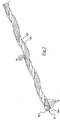
- cord 11 used in the belt structure 10 of tyre 100 of the present invention comprises a core 12 made of non metal material and a plurality of parallel metal wires 13 helically wound around the core 12 with a predetermined winding pitch.
- Core 12 comprises at least one elongated element.
- core 12 is made of an organic material.
- core 12 is made of an inorganic material, for example a material comprising glass, carbon, basalt, boron fibres.
- such material is suitably superficially coated with adhesive so as to provide a suitable adhesion to the surrounding mixture.
- the adhesive coating may be carried out by immersion of the elongated element forming the core 12 of cord 11 in a solution comprising the adhesive.
- cord 11 has a diameter comprised between about 0.5 mm and about 2.5 mm, more preferably between about 0.8 mm and about 1.5 mm.
- cord 11 has a diameter equal to 0.95 mm and in a second embodiment thereof, it has a diameter equal to 0.99 mm.
- cord 11 has a part load elongation greater than 0.5%, more preferably greater than 0.9%.
- Example of organic materials by which core 12 may be made are: polyethylene terephthalate, polyamide, aromatic polyamide, polyvinyl ester, polyvinyl alcohol, polyethylene naphthalate, polyketone, yarns from regenerated cellulose (such as rayon or lyocell), cotton and hybrids or mixtures thereof.
- said organic material comprises polyethylene terephthalate.
- core 12 is defined by two elongated elements 12a, 12b twisted on each other with a predetermined twisting pitch.
- core 12 may be defined by a single elongated element twisted on itself with a predetermined twisting pitch, or by more than two elongated elements twisted on each other with the same twisting pitch.
- the elongated elements 12a, 12b are preferably defined by respective textile elongated elements (or wires).
- the metal wires 13 are in direct contact with core 12, i.e. no intermediate layer is provided between core 12 and the metal wires 13. In particular, no coating layer of core 12 is provided.
- the metal wires 13 are five and they are in a condition of mutual contact.
- alternative embodiments are foreseen wherein the number of metal wires 13 is comprised between two and eight, more preferably between three and seven, the above metal wires 13 also being not all in mutual contact.
- the diameter of the metal wires 13 is preferably comprised between about 0.12 mm and about 0.35 mm, more preferably between about 0.17 mm and about 0.28 mm.
- the diameter of the metal wires 13 is equal to about 0.22 mm and in a second embodiment of cord 11, it is equal to about 25 mm.
- the metal wires 13 are arranged so as to not completely surround core 12.
- the metal wires 13 are arranged around core 12 so that, in any cross-section of cord 11, they are located at just an angular portion of an ideal circumference (indicated with letter C and a dashed line in figure 3 ) that circumscribes core 12.
- Such angular portion is defined by an angle ⁇ which is preferably comprised between about 40° and about 270°, more preferably between about 130° and about 190°, for example equal to about 150°.
- the winding pitch of the metal wires 13 is comprised between about 3 mm and about 16 mm, more preferably between about 5 mm and about 12.5 mm.
- the above winding pitch is equal to about 6.3 mm and in a second embodiment of cord 11, it is equal to about 10 mm.
- Cord 11 has an elongation at break greater than 2.5 %.
- the metal wires 13 are preferably all made of the same material.
- such material is steel, more preferably NT (Normal Tensile), HT (High Tensile), SHT (Super High Tensile) or UHT (Ultra High Tensile) steel.
- NT Normal Tensile
- HT High Tensile
- SHT Super High Tensile
- UHT Ultra High Tensile
- such steel has a carbon content smaller than about 1%.
- the carbon content is greater than or equal to about 0.7%.
- the steel has a tensile strength greater than about 2600 MPa.
- such tensile strength is smaller than about 4500 MPa.
- the particular arrangement of the metal wires 13 in the above cord 11 allows a crossed weft structure comprising a plurality of microcells 10a to be defined in the belt structure 10 of the zero degree type of tyre 100 of the present invention.
- reference numeral 10a in figure 4 is associated to only some of the microcells shown. :
- Each of such microcells 10a is defined by pieces 13' of a respective metal wire 13. inclined on one side with respect to a direction parallel to the equatorial plane X-X of tyre 100 and visible when looking at cord 11 from above, and by pieces 13" of the same metal wire 13 inclined on the opposite side with respect to the equatorial plane X-X of tyre 100 and visible when looking at cord 11 from below.
- respective thrust microcomponents are generated at said pieces 13', 13" of metal wires 13 of each of the above microcells 10a which effectively oppose the side stresses generated while running, in particular while running on bends.
- the diameter of core 12, the diameter of metal wires 13 and the winding pitch of metal wires 13 are selected so that pieces 13', 13'' are inclined with respect to a direction substantially parallel to the equatorial plane X-X of tyre 100 (which corresponds to the above substantially circumferential direction) by an angle comprised between 10° and 40°, more preferably between 15° and 30°.
- the Applicant has compared the load-elongation behaviour of a cord 11 usable in the belt structure of the zero degree type of tyre 100 of the present invention with that of a HE cord used in the belt structure of the zero degree type of a tyre that has been long manufactured and sold by the same Applicant and is appreciated by customers for its excellent features of structural resistance, performance (in terms of adhesion, driving stability, controllability, directionality, road-holding) and comfort.
- Curves A1 and A2 of figure 5 show the load-elongation diagram of two different embodiments of cord 11 described above.
- they are cords each comprising five metal wires helically wound on a core of textile material with a predetermined winding pitch.
- the metal wires are made of HT steel and have each a diameter equal to 0.22 mm.
- the textile core comprises two elongated elements of polyethylene terephthalate (polyester 1670x2 dtex), twisted with 330 twists/metre, in turn twisted with each other with 330 twists/metre.
- curve B of figure 5 shows the load-elongation diagram of the comparison HE cord.
- cord B is a high carbon content cord, hereinafter referred to as cord B.
- This cord has a diameter of 0.95 mm and comprises nine HT steel wires divided into three strands. The three strands are twisted together, each strand in turn comprising three metal wires twisted together.
- Cord B has the features indicated in tables 3 and 4 below.
- Figure 5 shows that cords A1, A2 and B have an increasing stiffness as the load increases (in fact, it is noted that the slope of the curves for elongations smaller than 1% is lower than that for elongations for example of about 3%). According to the Applicant, such increase in the stiffness is due to the fact that the resistance exerted by the textile core to the compression action exerted by the metal wires on the textile core increases as the load increases.
- Figure 5 also shows that at high loads, cord B has a modulus higher than that of cords A1, A2. According to the Applicant, this could have led to two conflicting results. On the one hand, the lower modulus could have led cords A1, A2 to respond with less reactivity and longer delay to the (longitudinal and side) stresses generated while running. However, on the other hand, the lower modulus of cords A1, A2 could have led to a better footprint shape, to the advantage of stability.
- tyre 100 of the present invention In order to assess the behaviour of tyre 100 of the present invention in terms of performance (adhesion, driving stability, controllability, directionality, road-holding), conformability (energy absorption upon impact) and comfort, the Applicant has carried out a number of comparative on-road tests using tyres comprising a belt structure of the zero degree type including a cord A1, A2 described above (such tyres thus corresponding to tyre 100 of the present invention) and known tyres comprising a belt structure of the zero degree type including cord B described above (hereinafter tyres B' or "comparison").
- Tyres 100 and B' were mounted on the rear wheel of a Nissan Hornet 600. On the contrary, tyres with belt structures of the zero degree type comprising cords B were mounted on the front wheel.
- the rear tyre had a size 180/55 R17 and therefore they only differed in the different type of cord used in the respective belt structures.
- the front tyre had a size 120/70 R17 and the same structure.
- the tester gave a very good overall assessment regarding the behaviour of tyre 100 of the present invention.
- tyre 100 of the present invention has an overall behaviour that is comparable with that of the already excellent comparison tyre chosen.
- the tester gave an opinion substantially identical to that given for the comparison tyre in terms of control (cold and hot skid), conformability (bump absorption and kick back absorption), comfort, solidity under fooprint and general driveability.
- tyre 100 of the present invention have, in addition to a behaviour typical of a tyre with a belt structure of the zero degree type, also a behaviour typical of a tyre with a belt structure of the crossed type.
- tyre 100 of the present invention also has the advantageous features in terms of reactivity, response readiness and oscillation control typical of tyres with belt structure of the crossed type.
- this may be ascribed to the presence of the above metal structure with crossed weft in the belt structure of the zero degree type of tyre 100 of the present invention, which not only makes up for the reduced resistance to stresses of the core of non metal material (which per se would have been a drawback), but it even imparts technical features to the belt structure of the zero degree type which can typically be more easily reached by tyres with belt structure of the crossed type.
- the use of a belt structure of the zero degree typer is advantageous since it does not introduce evenness problems on the tyre, allows a better braking on straight roads and causes on the motorcycle less vibrations and reactions to depressions and recesses, with a consequent benefit on the motorcycle stability while running.
- the use of a belt structure of the crossed type may be advantageous if it is desired for the tyre to have a higher drift stiffness and a shorter relaxation length, i.e. a shorter delay in the response to the stresses resulting from the wheel-road contact.
- tyres having a well optimized belt structure of the zero degree type they may be reached more easily using a belt structure of the crossed type.
- a belt structure of the crossed type may cause unevenness in the tyre and/or cause a stronger transferring of the side forces to the frame while running, as well as more sensitivity to depressions and recesses (and thus excessive reactivity), and/or more sensitivity to skids or vibrations induced by unevenness or by the tyre interaction with the rolling surface.
- this result was obtained also achieving a significant reduction in weight, thanks to the possibility of using, for the belt cords, a smaller number of metal wires than that of the HE cords typically used, and a core made of a light material.
- this has the advantage of providing a smaller non suspended mass in the tyre and thus of generating a lower moment of inertia around the axis of rotation of the tyre, so as to reduce the transfer of forces to the motorcycle frame, to the further advantage of stability.
Landscapes
- Engineering & Computer Science (AREA)
- Mechanical Engineering (AREA)
- Textile Engineering (AREA)
- Tires In General (AREA)
- Ropes Or Cables (AREA)
Claims (14)
- Pneu (100) pour motocycles, comprenant :- une structure de carcasse (2) ;- une structure de ceinture (10) agencée dans une position radialement externe par rapport à la structure de carcasse (2) ;- une bande de roulement (20) agencée dans une position radialement externe par rapport à la structure de ceinture (10) ;où ladite structure de ceinture (10) comprend au moins un câblé de renforcement (11) enroulé sur ladite structure de carcasse (2) selon des bobines adjacentes (11a) orientées le long d'une direction essentiellement circonférentielle ;
où ledit au moins un câblé de renforcement (11) comprend :- un noyau (12) réalisé en un matériau non métallique, et- une pluralité de fils métalliques (13) essentiellement parallèles les uns aux autres et enroulés de manière hélicoïdale autour dudit noyau (12) avec un pas d'enroulement prédéterminé ;où lesdits fils métalliques (13) sont agencés autour dudit noyau (12) de sorte qu'ils soient situés, dans une coupe transversale quelconque du câblé de renforcement (11), à seulement une partie angulaire d'une circonférence idéale (C) qui entoure le noyau (12) ;
où ledit noyau (12) comprend au moins deux éléments allongés (12a, 12b) torsadés l'un sur l'autre ou un seul élément allongé torsadé sur lui-même ;
où ledit pneu présente un rapport de courbure supérieur à 0,200. - Pneu (100) selon la revendication 1, dans lequel ladite partie angulaire est définie par un angle compris entre environ 40° et environ 270°.
- Pneu selon la revendication 1 ou 2, dans lequel le diamètre dudit noyau (12), le diamètre desdits fils métalliques (13) et le pas d'enroulement desdits fils métalliques (13) sont choisis de sorte que les fils métalliques (13) soient inclinés par rapport à ladite direction essentiellement circonférentielle d'un angle compris entre 10° et 40°.
- Pneu (100) selon l'une quelconque des revendications précédentes, dans lequel le nombre desdits fils métalliques (13) est compris entre deux et huit.
- Pneu (100) selon l'une quelconque des revendications précédentes, dans lequel le nombre desdits fils métalliques (13) est égal à cinq.
- Pneu (100) selon l'une quelconque des revendications précédentes, dans lequel le diamètre desdits fils métalliques (13) est compris entre environ 0, 12 mm et environ 0,35 mm.
- Pneu (100) selon l'une quelconque des revendications précédentes, dans lequel lesdits fils métalliques (13) sont dans un état de contact essentiellement mutuel.
- Pneu (100) selon l'une quelconque des revendications précédentes, dans lequel ledit au moins un câblé de renforcement (11) présente un diamètre compris entre environ 0,5 mm et environ 2,5 mm.
- Pneu (100) selon l'une quelconque des revendications précédentes, dans lequel ledit pas d'enroulement est compris entre environ 3 mm et environ 16 mm.
- Pneu (100) selon l'une quelconque des revendications précédentes, dans lequel ledit au moins un câblé de renforcement (11) présente un allongement à la rupture supérieur à 2,5%.
- Pneu (100) selon l'une quelconque des revendications précédentes, dans lequel ledit au moins un câblé de renforcement (11) présente un allongement sous charge partielle supérieur à 0,5%.
- Pneu (100) selon l'une quelconque des revendications précédentes, dans lequel ledit noyau (12) comprend un matériau fibreux.
- Pneu (100) selon la revendication 12, dans lequel ledit matériau fibreux comprend un matériau inorganique choisi parmi des fibres de verre et/ou de carbone et/ou de basalte et/ou de bore.
- Pneu (100) selon la revendication 12, dans lequel ledit matériau fibreux comprend un matériau organique choisi parmi : le polyéthylène téréphtalate, le polyamide, le polyamide aromatique, l'ester polyvinylique, l'alcool polyvinylique, le polyéthylène naphtalate, une polycétone, des fils provenant de cellulose régénérée, le coton et des hybrides ou des mélanges de ceux-ci.
Applications Claiming Priority (3)
| Application Number | Priority Date | Filing Date | Title |
|---|---|---|---|
| ITMI20112394 | 2011-12-27 | ||
| US201161581912P | 2011-12-30 | 2011-12-30 | |
| PCT/IB2012/057593 WO2013098738A1 (fr) | 2011-12-27 | 2012-12-21 | Pneu pour motocycles |
Publications (2)
| Publication Number | Publication Date |
|---|---|
| EP2748015A1 EP2748015A1 (fr) | 2014-07-02 |
| EP2748015B1 true EP2748015B1 (fr) | 2017-03-29 |
Family
ID=45571687
Family Applications (1)
| Application Number | Title | Priority Date | Filing Date |
|---|---|---|---|
| EP12823044.8A Active EP2748015B1 (fr) | 2011-12-27 | 2012-12-21 | Pneu pour motocycles |
Country Status (6)
| Country | Link |
|---|---|
| US (1) | US20150122395A1 (fr) |
| EP (1) | EP2748015B1 (fr) |
| JP (1) | JP6185931B2 (fr) |
| CN (1) | CN103958218B (fr) |
| BR (1) | BR112014014311B1 (fr) |
| WO (1) | WO2013098738A1 (fr) |
Families Citing this family (13)
| Publication number | Priority date | Publication date | Assignee | Title |
|---|---|---|---|---|
| LU92527B1 (fr) * | 2012-12-25 | 2014-12-22 | Kordsa Global Endustriyel Iplik Ve Kord Bezi Sanayi Ve Ticaret As | Structure de câbles hybride |
| EP3086951B1 (fr) * | 2013-12-23 | 2019-10-23 | Pirelli Tyre S.p.A. | Pneu pour roues de véhicules de type poids lourd |
| CN109415847A (zh) * | 2016-04-08 | 2019-03-01 | 盖茨公司 | 用于增强聚合物制品的混合缆线和增强制品 |
| IT201600117754A1 (it) * | 2016-11-22 | 2018-05-22 | Pirelli | Pneumatico per motoveicoli |
| JP2018083594A (ja) * | 2016-11-25 | 2018-05-31 | 株式会社ブリヂストン | タイヤ |
| MX2021001244A (es) * | 2018-08-03 | 2021-03-25 | Pirelli | Neumatico para ruedas de vehiculo. |
| CN109049759A (zh) * | 2018-09-25 | 2018-12-21 | 北航(四川)西部国际创新港科技有限公司 | 复合材料轮毂及其制造方法 |
| BR112021020175A2 (pt) * | 2019-04-17 | 2021-12-21 | Pirelli | Pneu para rodas de veículo, e, cordonel de reforço híbrido |
| CN114829703A (zh) * | 2019-12-17 | 2022-07-29 | 倍耐力轮胎股份公司 | 用于车辆车轮的轮胎的金属增强帘线 |
| BR112022009757A2 (pt) * | 2019-12-17 | 2022-08-09 | Pirelli | Cabo de reforço metálico para pneus de rodas de veículos |
| IT202000014521A1 (it) | 2020-06-17 | 2021-12-17 | Pirelli | Pneumatico per ruote di veicoli |
| CN118043518A (zh) | 2021-09-28 | 2024-05-14 | 贝卡尔特公司 | 具有经适应的伸长性能的钢帘线 |
| CN114083940B (zh) * | 2021-11-30 | 2023-09-15 | 蓉驿时代科技有限公司 | 一种全方位防护自修复轮胎及其制备方法 |
Citations (1)
| Publication number | Priority date | Publication date | Assignee | Title |
|---|---|---|---|---|
| EP2000584A1 (fr) * | 2007-06-09 | 2008-12-10 | Continental Aktiengesellschaft | Câble hybride de renforcement pour produits élastomères, en particulier comme nappe carcasse ou bandage de pneus de véhicules |
Family Cites Families (15)
| Publication number | Priority date | Publication date | Assignee | Title |
|---|---|---|---|---|
| FR2260660B1 (fr) | 1974-02-12 | 1976-11-26 | Michelin & Cie | |
| IT1248851B (it) | 1990-06-14 | 1995-01-30 | Pirelli | Procedimento per la fabbricazione di pneumatici per veicoli a due ruote e pneumatici cosi' prodotti |
| JPH0641881A (ja) * | 1992-05-20 | 1994-02-15 | Bridgestone Corp | エラストマー製品補強用複合コード |
| JP3411615B2 (ja) * | 1993-04-14 | 2003-06-03 | 株式会社ブリヂストン | 空気入りラジアルタイヤ |
| JP3294378B2 (ja) * | 1993-04-21 | 2002-06-24 | 住友ゴム工業株式会社 | 空気入りタイヤ |
| JP3471863B2 (ja) * | 1993-09-30 | 2003-12-02 | 株式会社ブリヂストン | 二輪自動車用空気入りラジアルタイヤ |
| JPH0796712A (ja) * | 1993-09-30 | 1995-04-11 | Bridgestone Corp | 二輪自動車用空気入りラジアルタイヤ |
| DE10144833A1 (de) | 2001-09-12 | 2003-04-30 | Continental Ag | Verstärkungskord |
| DE102004036129A1 (de) * | 2004-07-24 | 2006-02-16 | Continental Aktiengesellschaft | Verstärkungscord für elastomere Erzeugnisse |
| JP4755488B2 (ja) * | 2005-11-25 | 2011-08-24 | 住友ゴム工業株式会社 | 自動二輪車用ラジアルタイヤ、及びそれに用いるバンドコード |
| FR2897076B1 (fr) | 2006-02-09 | 2008-04-18 | Michelin Soc Tech | Cable composite elastique pour pneumatique. |
| JP2010510124A (ja) * | 2006-11-22 | 2010-04-02 | ピレリ・タイヤ・ソチエタ・ペル・アツィオーニ | 軽量ビードコアを有するタイヤ |
| US8381505B2 (en) * | 2008-04-21 | 2013-02-26 | Pirelli Tyre S.P.A. | Metallic cord comprising preformed and non-preformed wires, rubber sheet comprising said cord and tyre comprising at least one layer derived from said rubber sheet |
| ATE550206T1 (de) * | 2008-05-28 | 2012-04-15 | Pirelli | Motorradreifen |
| JP4814979B2 (ja) * | 2009-06-12 | 2011-11-16 | 住友ゴム工業株式会社 | タイヤ用コード及びそれを用いた空気入りタイヤ |
-
2012
- 2012-12-21 JP JP2014549598A patent/JP6185931B2/ja active Active
- 2012-12-21 WO PCT/IB2012/057593 patent/WO2013098738A1/fr active Application Filing
- 2012-12-21 US US14/366,510 patent/US20150122395A1/en not_active Abandoned
- 2012-12-21 EP EP12823044.8A patent/EP2748015B1/fr active Active
- 2012-12-21 CN CN201280058148.XA patent/CN103958218B/zh active Active
- 2012-12-21 BR BR112014014311-0A patent/BR112014014311B1/pt active IP Right Grant
Patent Citations (1)
| Publication number | Priority date | Publication date | Assignee | Title |
|---|---|---|---|---|
| EP2000584A1 (fr) * | 2007-06-09 | 2008-12-10 | Continental Aktiengesellschaft | Câble hybride de renforcement pour produits élastomères, en particulier comme nappe carcasse ou bandage de pneus de véhicules |
Also Published As
| Publication number | Publication date |
|---|---|
| JP6185931B2 (ja) | 2017-08-23 |
| BR112014014311A2 (pt) | 2017-06-13 |
| US20150122395A1 (en) | 2015-05-07 |
| BR112014014311B1 (pt) | 2020-10-13 |
| JP2015506303A (ja) | 2015-03-02 |
| WO2013098738A1 (fr) | 2013-07-04 |
| EP2748015A1 (fr) | 2014-07-02 |
| CN103958218A (zh) | 2014-07-30 |
| CN103958218B (zh) | 2018-09-18 |
Similar Documents
| Publication | Publication Date | Title |
|---|---|---|
| EP2748015B1 (fr) | Pneu pour motocycles | |
| CN109219529B (zh) | 用于重载车辆车轮的轮胎 | |
| EP3552841B1 (fr) | Pneumatique | |
| CN109952209B (zh) | 摩托车轮胎 | |
| EP0928704B1 (fr) | Bandage pneumatique à haute courbure transversale pour véhicules à deux roues | |
| EP0950546B1 (fr) | Bandage pneumatique a haute courbure transversale, en particulier pour vehicule a deux roues | |
| EP2797754B1 (fr) | Pneu pour motocycles | |
| EP3086951B1 (fr) | Pneu pour roues de véhicules de type poids lourd | |
| JP2004067058A (ja) | 自動二輪車用空気入りタイヤ | |
| US20130168003A1 (en) | Pneumatic tire | |
| JP4349607B2 (ja) | 自動二輪車用空気入りタイヤ | |
| EP3898276B1 (fr) | Pneumatique destiné à des roues de véhicule | |
| US6244315B1 (en) | Tyre with high transverse curvature coefficient in particular for a two-wheeled vehicle | |
| EP3829898B1 (fr) | Pneu pour roues de véhicule | |
| EP2380755B1 (fr) | Nappe recouvrant l'armature de sommet pour pneu | |
| EP0928703A1 (fr) | Bandage pneumatique à grande courbure transversale pour véhicule à deux roues, et son procédé de fabrication | |
| WO2022014403A1 (fr) | Bandage pneumatique | |
| JP2001233012A (ja) | 空気入りラジアルタイヤの装着方法及び空気入りラジアルタイヤ | |
| WO2023223246A1 (fr) | Pneumatique destiné à des roues de véhicule |
Legal Events
| Date | Code | Title | Description |
|---|---|---|---|
| PUAI | Public reference made under article 153(3) epc to a published international application that has entered the european phase |
Free format text: ORIGINAL CODE: 0009012 |
|
| 17P | Request for examination filed |
Effective date: 20140321 |
|
| AK | Designated contracting states |
Kind code of ref document: A1 Designated state(s): AL AT BE BG CH CY CZ DE DK EE ES FI FR GB GR HR HU IE IS IT LI LT LU LV MC MK MT NL NO PL PT RO RS SE SI SK SM TR |
|
| DAX | Request for extension of the european patent (deleted) | ||
| 17Q | First examination report despatched |
Effective date: 20151116 |
|
| GRAP | Despatch of communication of intention to grant a patent |
Free format text: ORIGINAL CODE: EPIDOSNIGR1 |
|
| RIC1 | Information provided on ipc code assigned before grant |
Ipc: D07B 1/06 20060101ALI20160923BHEP Ipc: B60C 9/00 20060101AFI20160923BHEP Ipc: B60C 9/22 20060101ALI20160923BHEP Ipc: B60C 9/20 20060101ALI20160923BHEP Ipc: D07B 1/00 20060101ALI20160923BHEP |
|
| INTG | Intention to grant announced |
Effective date: 20161031 |
|
| GRAS | Grant fee paid |
Free format text: ORIGINAL CODE: EPIDOSNIGR3 |
|
| GRAA | (expected) grant |
Free format text: ORIGINAL CODE: 0009210 |
|
| AK | Designated contracting states |
Kind code of ref document: B1 Designated state(s): AL AT BE BG CH CY CZ DE DK EE ES FI FR GB GR HR HU IE IS IT LI LT LU LV MC MK MT NL NO PL PT RO RS SE SI SK SM TR |
|
| REG | Reference to a national code |
Ref country code: GB Ref legal event code: FG4D |
|
| REG | Reference to a national code |
Ref country code: CH Ref legal event code: EP |
|
| REG | Reference to a national code |
Ref country code: AT Ref legal event code: REF Ref document number: 879364 Country of ref document: AT Kind code of ref document: T Effective date: 20170415 |
|
| REG | Reference to a national code |
Ref country code: IE Ref legal event code: FG4D |
|
| REG | Reference to a national code |
Ref country code: DE Ref legal event code: R096 Ref document number: 602012030558 Country of ref document: DE |
|
| REG | Reference to a national code |
Ref country code: RO Ref legal event code: EPE |
|
| PG25 | Lapsed in a contracting state [announced via postgrant information from national office to epo] |
Ref country code: LT Free format text: LAPSE BECAUSE OF FAILURE TO SUBMIT A TRANSLATION OF THE DESCRIPTION OR TO PAY THE FEE WITHIN THE PRESCRIBED TIME-LIMIT Effective date: 20170329 Ref country code: NO Free format text: LAPSE BECAUSE OF FAILURE TO SUBMIT A TRANSLATION OF THE DESCRIPTION OR TO PAY THE FEE WITHIN THE PRESCRIBED TIME-LIMIT Effective date: 20170629 Ref country code: HR Free format text: LAPSE BECAUSE OF FAILURE TO SUBMIT A TRANSLATION OF THE DESCRIPTION OR TO PAY THE FEE WITHIN THE PRESCRIBED TIME-LIMIT Effective date: 20170329 Ref country code: FI Free format text: LAPSE BECAUSE OF FAILURE TO SUBMIT A TRANSLATION OF THE DESCRIPTION OR TO PAY THE FEE WITHIN THE PRESCRIBED TIME-LIMIT Effective date: 20170329 Ref country code: GR Free format text: LAPSE BECAUSE OF FAILURE TO SUBMIT A TRANSLATION OF THE DESCRIPTION OR TO PAY THE FEE WITHIN THE PRESCRIBED TIME-LIMIT Effective date: 20170630 |
|
| REG | Reference to a national code |
Ref country code: NL Ref legal event code: MP Effective date: 20170329 |
|
| REG | Reference to a national code |
Ref country code: AT Ref legal event code: MK05 Ref document number: 879364 Country of ref document: AT Kind code of ref document: T Effective date: 20170329 |
|
| PG25 | Lapsed in a contracting state [announced via postgrant information from national office to epo] |
Ref country code: RS Free format text: LAPSE BECAUSE OF FAILURE TO SUBMIT A TRANSLATION OF THE DESCRIPTION OR TO PAY THE FEE WITHIN THE PRESCRIBED TIME-LIMIT Effective date: 20170329 Ref country code: LV Free format text: LAPSE BECAUSE OF FAILURE TO SUBMIT A TRANSLATION OF THE DESCRIPTION OR TO PAY THE FEE WITHIN THE PRESCRIBED TIME-LIMIT Effective date: 20170329 Ref country code: BG Free format text: LAPSE BECAUSE OF FAILURE TO SUBMIT A TRANSLATION OF THE DESCRIPTION OR TO PAY THE FEE WITHIN THE PRESCRIBED TIME-LIMIT Effective date: 20170629 Ref country code: SE Free format text: LAPSE BECAUSE OF FAILURE TO SUBMIT A TRANSLATION OF THE DESCRIPTION OR TO PAY THE FEE WITHIN THE PRESCRIBED TIME-LIMIT Effective date: 20170329 |
|
| PG25 | Lapsed in a contracting state [announced via postgrant information from national office to epo] |
Ref country code: NL Free format text: LAPSE BECAUSE OF FAILURE TO SUBMIT A TRANSLATION OF THE DESCRIPTION OR TO PAY THE FEE WITHIN THE PRESCRIBED TIME-LIMIT Effective date: 20170329 |
|
| PG25 | Lapsed in a contracting state [announced via postgrant information from national office to epo] |
Ref country code: CZ Free format text: LAPSE BECAUSE OF FAILURE TO SUBMIT A TRANSLATION OF THE DESCRIPTION OR TO PAY THE FEE WITHIN THE PRESCRIBED TIME-LIMIT Effective date: 20170329 Ref country code: AT Free format text: LAPSE BECAUSE OF FAILURE TO SUBMIT A TRANSLATION OF THE DESCRIPTION OR TO PAY THE FEE WITHIN THE PRESCRIBED TIME-LIMIT Effective date: 20170329 Ref country code: ES Free format text: LAPSE BECAUSE OF FAILURE TO SUBMIT A TRANSLATION OF THE DESCRIPTION OR TO PAY THE FEE WITHIN THE PRESCRIBED TIME-LIMIT Effective date: 20170329 Ref country code: EE Free format text: LAPSE BECAUSE OF FAILURE TO SUBMIT A TRANSLATION OF THE DESCRIPTION OR TO PAY THE FEE WITHIN THE PRESCRIBED TIME-LIMIT Effective date: 20170329 Ref country code: SK Free format text: LAPSE BECAUSE OF FAILURE TO SUBMIT A TRANSLATION OF THE DESCRIPTION OR TO PAY THE FEE WITHIN THE PRESCRIBED TIME-LIMIT Effective date: 20170329 |
|
| PG25 | Lapsed in a contracting state [announced via postgrant information from national office to epo] |
Ref country code: SM Free format text: LAPSE BECAUSE OF FAILURE TO SUBMIT A TRANSLATION OF THE DESCRIPTION OR TO PAY THE FEE WITHIN THE PRESCRIBED TIME-LIMIT Effective date: 20170329 Ref country code: PL Free format text: LAPSE BECAUSE OF FAILURE TO SUBMIT A TRANSLATION OF THE DESCRIPTION OR TO PAY THE FEE WITHIN THE PRESCRIBED TIME-LIMIT Effective date: 20170329 Ref country code: PT Free format text: LAPSE BECAUSE OF FAILURE TO SUBMIT A TRANSLATION OF THE DESCRIPTION OR TO PAY THE FEE WITHIN THE PRESCRIBED TIME-LIMIT Effective date: 20170731 Ref country code: IS Free format text: LAPSE BECAUSE OF FAILURE TO SUBMIT A TRANSLATION OF THE DESCRIPTION OR TO PAY THE FEE WITHIN THE PRESCRIBED TIME-LIMIT Effective date: 20170729 |
|
| REG | Reference to a national code |
Ref country code: FR Ref legal event code: PLFP Year of fee payment: 6 |
|
| REG | Reference to a national code |
Ref country code: DE Ref legal event code: R097 Ref document number: 602012030558 Country of ref document: DE |
|
| PG25 | Lapsed in a contracting state [announced via postgrant information from national office to epo] |
Ref country code: DK Free format text: LAPSE BECAUSE OF FAILURE TO SUBMIT A TRANSLATION OF THE DESCRIPTION OR TO PAY THE FEE WITHIN THE PRESCRIBED TIME-LIMIT Effective date: 20170329 |
|
| PLBE | No opposition filed within time limit |
Free format text: ORIGINAL CODE: 0009261 |
|
| STAA | Information on the status of an ep patent application or granted ep patent |
Free format text: STATUS: NO OPPOSITION FILED WITHIN TIME LIMIT |
|
| 26N | No opposition filed |
Effective date: 20180103 |
|
| PG25 | Lapsed in a contracting state [announced via postgrant information from national office to epo] |
Ref country code: SI Free format text: LAPSE BECAUSE OF FAILURE TO SUBMIT A TRANSLATION OF THE DESCRIPTION OR TO PAY THE FEE WITHIN THE PRESCRIBED TIME-LIMIT Effective date: 20170329 |
|
| REG | Reference to a national code |
Ref country code: CH Ref legal event code: PL |
|
| REG | Reference to a national code |
Ref country code: IE Ref legal event code: MM4A |
|
| PG25 | Lapsed in a contracting state [announced via postgrant information from national office to epo] |
Ref country code: LU Free format text: LAPSE BECAUSE OF NON-PAYMENT OF DUE FEES Effective date: 20171221 Ref country code: MT Free format text: LAPSE BECAUSE OF NON-PAYMENT OF DUE FEES Effective date: 20171221 |
|
| REG | Reference to a national code |
Ref country code: BE Ref legal event code: MM Effective date: 20171231 |
|
| PG25 | Lapsed in a contracting state [announced via postgrant information from national office to epo] |
Ref country code: IE Free format text: LAPSE BECAUSE OF NON-PAYMENT OF DUE FEES Effective date: 20171221 |
|
| PG25 | Lapsed in a contracting state [announced via postgrant information from national office to epo] |
Ref country code: LI Free format text: LAPSE BECAUSE OF NON-PAYMENT OF DUE FEES Effective date: 20171231 Ref country code: CH Free format text: LAPSE BECAUSE OF NON-PAYMENT OF DUE FEES Effective date: 20171231 Ref country code: BE Free format text: LAPSE BECAUSE OF NON-PAYMENT OF DUE FEES Effective date: 20171231 |
|
| PG25 | Lapsed in a contracting state [announced via postgrant information from national office to epo] |
Ref country code: MC Free format text: LAPSE BECAUSE OF FAILURE TO SUBMIT A TRANSLATION OF THE DESCRIPTION OR TO PAY THE FEE WITHIN THE PRESCRIBED TIME-LIMIT Effective date: 20170329 Ref country code: HU Free format text: LAPSE BECAUSE OF FAILURE TO SUBMIT A TRANSLATION OF THE DESCRIPTION OR TO PAY THE FEE WITHIN THE PRESCRIBED TIME-LIMIT; INVALID AB INITIO Effective date: 20121221 |
|
| PG25 | Lapsed in a contracting state [announced via postgrant information from national office to epo] |
Ref country code: CY Free format text: LAPSE BECAUSE OF NON-PAYMENT OF DUE FEES Effective date: 20170329 |
|
| PG25 | Lapsed in a contracting state [announced via postgrant information from national office to epo] |
Ref country code: MK Free format text: LAPSE BECAUSE OF FAILURE TO SUBMIT A TRANSLATION OF THE DESCRIPTION OR TO PAY THE FEE WITHIN THE PRESCRIBED TIME-LIMIT Effective date: 20170329 |
|
| PG25 | Lapsed in a contracting state [announced via postgrant information from national office to epo] |
Ref country code: TR Free format text: LAPSE BECAUSE OF FAILURE TO SUBMIT A TRANSLATION OF THE DESCRIPTION OR TO PAY THE FEE WITHIN THE PRESCRIBED TIME-LIMIT Effective date: 20170329 |
|
| PG25 | Lapsed in a contracting state [announced via postgrant information from national office to epo] |
Ref country code: AL Free format text: LAPSE BECAUSE OF FAILURE TO SUBMIT A TRANSLATION OF THE DESCRIPTION OR TO PAY THE FEE WITHIN THE PRESCRIBED TIME-LIMIT Effective date: 20170329 |
|
| PGFP | Annual fee paid to national office [announced via postgrant information from national office to epo] |
Ref country code: GB Payment date: 20231227 Year of fee payment: 12 |
|
| PGFP | Annual fee paid to national office [announced via postgrant information from national office to epo] |
Ref country code: RO Payment date: 20231205 Year of fee payment: 12 Ref country code: IT Payment date: 20231220 Year of fee payment: 12 Ref country code: FR Payment date: 20231227 Year of fee payment: 12 |
|
| PGFP | Annual fee paid to national office [announced via postgrant information from national office to epo] |
Ref country code: DE Payment date: 20231229 Year of fee payment: 12 |