EP2747962B1 - Hair cutting device with improved cutting member - Google Patents
Hair cutting device with improved cutting member Download PDFInfo
- Publication number
- EP2747962B1 EP2747962B1 EP12787902.1A EP12787902A EP2747962B1 EP 2747962 B1 EP2747962 B1 EP 2747962B1 EP 12787902 A EP12787902 A EP 12787902A EP 2747962 B1 EP2747962 B1 EP 2747962B1
- Authority
- EP
- European Patent Office
- Prior art keywords
- cutting
- moving
- cutting member
- distal end
- flank
- Prior art date
- Legal status (The legal status is an assumption and is not a legal conclusion. Google has not performed a legal analysis and makes no representation as to the accuracy of the status listed.)
- Not-in-force
Links
Images


Classifications
-
- B—PERFORMING OPERATIONS; TRANSPORTING
- B26—HAND CUTTING TOOLS; CUTTING; SEVERING
- B26B—HAND-HELD CUTTING TOOLS NOT OTHERWISE PROVIDED FOR
- B26B19/00—Clippers or shavers operating with a plurality of cutting edges, e.g. hair clippers, dry shavers
- B26B19/38—Details of, or accessories for, hair clippers, or dry shavers, e.g. housings, casings, grips, guards
- B26B19/3846—Blades; Cutters
-
- B—PERFORMING OPERATIONS; TRANSPORTING
- B26—HAND CUTTING TOOLS; CUTTING; SEVERING
- B26B—HAND-HELD CUTTING TOOLS NOT OTHERWISE PROVIDED FOR
- B26B19/00—Clippers or shavers operating with a plurality of cutting edges, e.g. hair clippers, dry shavers
- B26B19/38—Details of, or accessories for, hair clippers, or dry shavers, e.g. housings, casings, grips, guards
- B26B19/3893—Manufacturing of shavers or clippers or components thereof
-
- Y—GENERAL TAGGING OF NEW TECHNOLOGICAL DEVELOPMENTS; GENERAL TAGGING OF CROSS-SECTIONAL TECHNOLOGIES SPANNING OVER SEVERAL SECTIONS OF THE IPC; TECHNICAL SUBJECTS COVERED BY FORMER USPC CROSS-REFERENCE ART COLLECTIONS [XRACs] AND DIGESTS
- Y10—TECHNICAL SUBJECTS COVERED BY FORMER USPC
- Y10T—TECHNICAL SUBJECTS COVERED BY FORMER US CLASSIFICATION
- Y10T83/00—Cutting
- Y10T83/04—Processes
Definitions
- the invention relates to the field of hair cutting devices, and more specially to a moving cutting member of a cutting unit of the hair cutting device.
- a hair cutting device is a device for cutting hair. It comprises a cutting unit and driving means for actuating the cutting unit.
- the cutting unit consists of two comb-like cutting members.
- One cutting member is a stationary cutting member, which is in contact with the skin of the user.
- the other cutting member is a moving cutting member, which is placed adjacent and in contact with the stationary cutting member.
- the moving cutting member is coupled to the driving means for driving movement relative to the stationary cutting member.
- the stationary cutting member may comprise rounded tips to avoid injury to the skin.
- the driving means may be a pincer-like hand lever, an electric motor with eccentric or an oscillating armature drive.
- the driving means may be part of a handset and also occur in high-performance devices on joints or flexible shafts.
- JP 2000 308768 A there is disclosed a hair clipper device comprising hair clipper blades, wherein the hair clipper blades have groove blades in a peculiar shape at side edges of the main bodies of the blades, wherein the groove blades are formed such that open ends have an aperture width permitting linear materials such as hair to be cut to penetrate thereinto, and wherein the groove blades have wide groove parts wider than the aperture width of the open ends in parts between the open ends and the insides of the grooves of the groove blades.
- the hair clipper blades are arranged one upon another such that the two blades are opposite, and that the hair clipper blades are adapted to slide in the direction of the width of the groove blades.
- JP 52 046969 A there is disclosed an edge shaving cutter edge for an electric razor comprising stationary and movable cutting edges provided with slits, wherein a cutting angle is formed by the stationary and the movable cutting edges that extends towards a root portion of the slits.
- a blade structure of an electric hair trimmer comprising a blade set which is installed at a front end of an electric hair trimmer, with the blade set being constituted by a fixed plate and a vibration seat which is connected to a movable blade, with a front end of the fixed blade and the movable blade being provided with a plurality of teeth, and with the vibration seat being driven by a motor in an interior of the body, enabling the movable blade to be overlapped with the fixed blade to form alternate movement, wherein lower sections of edge parts of the movable blade are extended outward to form externally expanded surfaces comprising sharp transection angles.
- the European patent application EP 1 894 685 A1 discloses a hair cutting device with a modified moving cutting member in order to improve catching hair.
- the European patent application is based on the quantity of cutting elements for cutting the hair together with blade pieces of the stationary cutting member.
- the modified moving cutting member uses the double amount of the cutting elements.
- the double amount of cutting elements does not improve the cutting performance of the hair cutting device satisfactorily.
- a cutting unit for a hair cutting device comprising a stationary cutting member, wherein the stationary cutting member comprises a plurality of blade pieces, and a moving cutting member, wherein multiple cutting elements are extending along a middle axis from a base sheet of the moving member, wherein each cutting element of the moving cutting element comprises a proximal end connected to the base sheet with a first width and a distal end with a second width facing away from the base sheet, a first flank and a second flank each extending from the proximal end to the distal end, wherein the first flank and/or the second flank each comprising a blade edge extending at least partially along the first and/or second flank, wherein the second width of the distal end is larger than the first width of the proximal end, wherein the distal end comprises at least one cutting edge, wherein the at least one cutting edge is facing away from the base sheet, and wherein the at least one cutting edge is formed as a recess at the distal end.
- the stationary cutting member may comprise a comb like shape, wherein a plurality blade pieces may extrude from a base sheet of the stationary cutting member.
- the moving cutting member may also comprise a comb-like shape, wherein a plurality of cutting elements is protruding in parallel from a base sheet.
- the moving cutting member may be placed on the stationary cutting member so that the moving cutting member and the stationary cutting member are in contact with each other.
- Each cutting element of the moving cutting member comprises a proximal end which is connected with the base sheet and each cutting element comprises a distal end facing away from the base sheet.
- each cutting element of the moving cutting member comprises a first flank and a second flank each extending from the proximal end to the distal end.
- the cutting elements of the moving cutting member may be arranged in a same direction in which the stationary blade pieces of the stationary cutting member are arranged.
- the blade pieces of the stationary cutting member and the cutting elements of the moving cutting member may be arranged in such a way that the blade pieces of the stationary cutting member and the corresponding first flanks and/or the second flanks of the moving cutting member are adjacent to each other.
- the moving cutting member may be coupled to driving means, for example a manual lever or an electrical motor, for driving movement of the moving cutting member relative to the stationary cutting member, in particular a sideways movement.
- the moving cutting member may be driven in an oscillating movement, wherein the cutting elements of the moving cutting member are moved towards and over in the movement direction of the adjacent stationary blade pieces of the stationary cutting member.
- Each cutting element of the moving cutting member comprises a first width at the proximal end and a second width at the distal end. The first width at the proximal end of each cutting element of the moving cutting member may be the distance between the protrusion of each cutting element when it protrudes out of the base sheet.
- the second width of the distal end of each cutting element of the moving cutting member is the width of the distal end.
- the first flank and/or the second flank may at least comprise partially a blade edge.
- the blade edge may be directed towards the adjacent stationary blade pieces of the stationary cutting member. The hair will be cut by moving the cutting elements sideways towards the in moving direction adjacent blade pieces.
- first flank and/or second flank comprise a first section adjacent to the proximal end and a second section adjacent to the first section and the distal end, wherein the first section and/or the second section are at least partially curved.
- the second width at the distal end may be reduced towards the proximal end until the second section connects to the first section.
- the width of the second section may be reduced to the width of the first section.
- the reduction of the second width may be achieved by a curve.
- each cutting element comprises at the distal end a larger width than at the proximal end, wherein, each cutting element may comprise a sickle shape which simplifies the catching of hair.
- the first section is formed at least partially essential parallel to the middle axis. This improves the catching of hair by providing a room where the hair may be guided to.
- the second width of the distal end catches the hair and guides the hair with the help of the reduction of the width of the second section towards the partially essential parallel part of the first section. Since the first section comprises a smaller width than the second width the hair are not able to leave the space between the blade pieces of the stationary cutting member and the first flanks and/or second flanks of the moving cutting member. The larger width of the second width is blocking the way out.
- the cutting performance may be improved, since a further cutting area is provided at the distal end.
- hair which may not be caught between the flanks of the cutting elements and the in moving direction of the cutting elements adjacent stationary blade pieces of the stationary cutting member may be cut by the cutting edges, when the cutting member is moved sideways, in particular in an oscillating movement, towards the in moving direction of the cutting members adjacent blade pieces of the stationary cutting member.
- the cutting edge at the distal end is formed V-shaped, in particular in a V-shaped recess.
- the opening angle of the V-shaped cutting edge may be about 170°.
- the cutting edge of the distal end may be formed a U-shape like, an oval-shape or a spade-shape. Thereby, the length of the cutting edges may be increased and the cutting performance may be increased.
- the cutting edge at the distal end comprises a recess, wherein the recess may extend from an opening of the distal end along the middle axis towards a bottom end of the recess, whereby the opening is a gap at the distal end.
- the cutting edge may be formed onto the side of the recess.
- the bottom end of the recess may comprise a larger width than the opening of the recess at the distal end.
- the cutting elements comprise a cross section with a trapezoid shape, a triangle shape or a curved shape.
- the cutting elements may comprise for example a flat shape, whereby the flat shape may be formed in a rectangular shape, in particular in a trapezoid shape.
- the trapezoid shape may comprise a long base and a short base, whereby the long base and the short base are parallel to each other.
- the long base and the short base may be connected to each other by sides, whereby the sides may be the first flank and the second flank.
- the trapezoid shape may be an orthogonal trapezoid, an isosceles trapezoid, a parallelogram or in particular a symmetrical trapezoid.
- the short base of the trapezoid shape may comprise a curved shape, whereby the curved shape may be formed towards in direction of the long base.
- the blade edges may be arranged at the edge of the connection between the long base and the first flank and/or second flank.
- the cross section of the cutting element may comprise a triangle shale, in particular an isosceles triangle shape.
- the base angle of the isosceles triangle may be in particular an angle of about 45°.
- the blade edges may be arranged at the edge of the connection between the hypotenuse and the first flank and/or second flank.
- the cross section of the cutting edge may comprise a curved shape, whereby in the curved shape a long tangent angle may be in particular an angle of about 45°.
- the blade edges may be arranged at the edge of the connection between a chord and a circular arc of the curved shape.
- the first flanks and or the second flanks may provide a wedge along which the hair may glide in an oblique shearing process.
- the wedge may comprise a constant wedge angle of about 45°. Thereby, the cutting performance may be increased.
- the invention is further related to a production method for producing a moving cutting member for a cutting unit, comprising the steps of: providing a blank of the moving cutting member, wherein multiple cutting elements are extending along a middle axis from a base sheet of the moving cutting member, wherein each cutting element of the moving cutting member comprises a proximal end connected to the base sheet and a distal end facing away from the base sheet; widening of the distal end of the cutting elements of the moving cutting member by a cold forming process, such that a second width of the distal end is larger than a first width of the proximal end; and grinding of blade edges on the first flanks and/or second flanks of the cutting elements of the moving cutting member.
- a blank of the moving cutting member may be produced by cutting, sintering, by laser cutting, by die casting, by milling, etc, in particular by coining.
- the blank of the moving cutting member may comprise a comb like shape and the second widths of the cutting elements comprise the same width or a smaller width than the first width.
- the distal ends of the section may be widened to increase the second width until the second width comprises a larger width than the first width. Further, by the use of a cold forming process for widening the distal end the corrosion resistance of the moving cutting member in particular of the blade edges of the cutting elements, may be improved.
- the production efficiency may be increased, since it is possible to save energy for heating up, costs for heating up and time for cooling down of the moving cutting member before a further production step.
- the manufacturing of a constant wedge angle from the distal end to the proximal end may be possible with a low amount of for example about 45°.
- the production method comprises the further step of providing cutting edges at the distal ends and grinding of the cutting edges.
- the cutting edges may be produced during the widening of the second section or in a later production process. Thereby, a larger cutting length for cutting hair may be provided.
- a surface facing towards the stationary cutting member in an assembled state of the hair cutting device may be flattened, in particularly by grinding.
- the invention is further related to a use of a haircutting device with a cutting unit for cutting hair, comprising the steps of: catching a plurality of hairs between the stationary blade pieces of the stationary cutting member and first flanks and/or second flanks of the cutting elements of the moving cutting member; moving the first flanks and/or the second flanks of the cutting elements of the moving cutting member towards the corresponding stationary blade pieces of the adjacent stationary cutting member; cutting the hairs by an oblique shearing process, wherein the hairs are gliding along the blade edges of the first flanks and/or second flanks by following the first flanks and/or second flanks of the moving cutting member.
- the hair are caught for example by a sickle shaped second section, when the first flanks and/or the second flanks of the cutting elements of the moving cutting member are moving towards the in moving direction adjacent stationary blade edges of stationary cutting member.
- the moving cutting member may be coupled to driving means, for example a manual lever or an electrical motor, for driving movement of the moving cutting member relative to the stationary cutting member, in particular a sideways movement.
- the moving cutting member may be driven in an oscillating movement. Thereby the cutting elements of the moving cutting member are moved towards and are moved over the in moving direction adjacent stationary blade pieces of the stationary cutting member. Thereby, the hair will be cut in an oblique shearing process.
- a sickle like shape of the cutting element the second width at the distal end is able to catch the hair.
- the hair are pressed against the blade edge.
- the hair are gliding and following the curve of the blade edge in the second Section and are pushed thereby further towards the middle axis of the cutting element and thereby the hair are cut by an oblique shearing process, which is similar to a cut achieved by a knife.
- the use of the device for cutting hair further comprises the step of cutting hair with the cutting edges of the distal ends of the cutting elements of the moving cutting member.
- the hair will be cut in an oblique shearing process.
- the hairs are caught by the cutting edges of the distal ends.
- the hair glide along the cutting edges of the distal ends, when the cutting elements are moved towards the in movement direction adjacent stationary blade pieces of the stationary cutting member.
- the cutting performance may be improved, since the cutting edges provide an additional cutting length.
- Fig. 1 is showing a detailed view of two cutting elements 11 of a moving cutting member 10 of a cutting unit (not shown) of a hair cutting device (not shown).
- the moving cutting member 10 comprises a comb-like shape, wherein multiple cutting elements 11 are protruding from a base sheet 12.
- Each cutting element 11 comprises a proximal end 14, which is connected to the base sheet 12.
- a distal end 16 At the opposite side of the proximal end 14 of the cutting element 11 is a distal end 16, which is facing away from the base sheet 12.
- the distal end 16 comprises a second width W2 which is a larger width than a first width W1 of the proximal end 14..
- the first width W1 at the proximal end 14 of each cutting element 11 of the moving cutting member comprises the distance between the protrusion of each cutting element 11 when it protrudes out of the base sheet 12.
- the second width W2 of the distal end 16 of each cutting element of the moving cutting member is the width of the distal end 16.
- the second width W2 of the distal end 16 may be produced by a cold forming process.
- the cutting element 11 comprises a first flank 18 and a second flank 20.
- the first flank 18 and the second flank 20 are extending from the proximal end 14 towards the distal end 16.
- the first flank 18 and the second flank 20 comprise each at least partially a blade edge 22 formed thereon, so the cutting element 10 is able to cut hair.
- the cutting element 11 comprises a first section 40, which is adjacent to the proximal end 14, and a second section 42, which is adjacent to the first section 40 and the distal end 16. Furthermore, the first section 40 and the second section 42 are at least partially curved. The first flank 18 and the second flank 20 comprise a radius at the connection of the proximal end 14 with the base sheet 12.
- the first flank 18 and the second flank 20 of the first section 40 are starting from the proximal end 14 partially essential parallel to a middle axis A. At the connection between the first section 40 and the second section 42 the width go over to be inclined to the middle axis A until the first flank 18 and the second flank 20 are connected to the distal end 16. As shown in Fig. 1 the first flank 18 and the second flank 20 of the second Section 42 are going over to be inclined to the middle axis with a curve.
- a distance between the distal end 16 and the connection between the first section S1 and the second section S2 is provided with a sickle like shape. This improves the catching of hair during the hair cutting process. Further, by providing a curve at the first flank 18 and the second flank 20 at the second section 42 a homogeneously motion of the hair along the curve of the blade edge 22 may be achieved.
- the main principle is to catch hair by many sickles. The so caught hair do not leave the cutting area and so the efficiency of cutting hair may be improved over cutting members with common cutting elements of a common hair cutting devices. This oblique shearing process may be explained by the way a hair 26 may be cut with a straight blade 28, for example a knife 24.
- Fig. 2 shows an illustration of a principle of an oblique cutting with a knife 24. It is possible to cut an object 26 with a relative movement of the knife 24. The object 26 is cut without a shear movement transverse to a longitudinal extension of the object 26, whereby the object 26 may be moved slightly in longitudinal extension.
- the object 26 is fixed, for example by a hand of a user (not shown), in the horizontal plane B in which the object 26 is arranged essentially with its longitudinal extension. A blade 28 of a knife 24 is pressed onto the object 26 and the knife 24 is pulled down in direction of an arrow 30.
- Fig. 2b it may be seen that the object 26 is still fixed in the horizontal plane B and is not moved.
- the knife 24 is moved in direction of the arrow 30 and half of the blade 28 has already cut through the half of the object 26.
- the object 26 is still fixed in plane B and the blade 28 of the knife 24 has cut through the object 26.
- This principle may be transferred onto to one embodiment of the cutting element of the invention.
- the sickle like shape of the cutting element 11 By the sickle like shape of the cutting element 11, the second width W2 at the distal end 16 is able to catch the hair.
- the hair are pressed against the blade edge 22.
- the hair are gliding and following the curve of the blade edge 22 in the second Section 42 and are pushed thereby further towards the middle axis A of the cutting element 11 and thereby a cut of a drawing knife 24 is created.
- Fig. 3 shows a further embodiment of the invention.
- the cutting element 11 comprises a cutting edge 32 formed as a recess at the distal end 16.
- the cutting edge 32 in Fig. 3 is formed V-shaped.
- Fig. 4 shows another example of a cutting edge 32 at the distal end 16 of the cutting element 11.
- the cutting edge 32 is a recess 36 and comprises at a bottom end 34 a larger width than the opening 36.
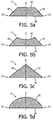
- Fig. 5a to 5d show cross sections of a cutting element 11 of Fig. 1 .
- the cutting element 11 in Fig. 1 has been cut along the cutting line C-C.
- the detailed views in Fig. 5a to 5d are simplified and only show the cross section of the first section 40 of the cutting element 11, which has the same shape as the cutting clement 16 of a blank(not shown) of the cutting member 12 before a distal end 16 of the cutting clement 16 is widened.
- blade edges 22 may be grinded onto the first flank 18 and/or second flank 20.
- the cross section of the cutting element 11 comprises a trapezoid shape, in particular in a symmetrical trapezoid shape.
- the cutting element 11 comprises a long base 44 and a short base 46 which are parallel to each other.
- the long base 44 and the short base 46 are spaced from each other along the middle axis D.
- the trapezoid shape cutting element 11 comprises sides which are connecting the long base 44 to the short base 46.
- the sides are a first flank 18 and a second flank 20 of the cutting element 11.
- the cutting element 11 may comprise blade edges 22, which may be arranged at the connection between the long base and the first flank 18 and/or second flank 22.
- cross section of the cutting element 11 comprises a trapezoid shape, in particular in a symmetrical trapezoid shape.
- the cutting element 11 comprises a long base 44 and a short base 46 which are parallel to each other.
- the long base 44 and the short base 46 are spaced from each other along the middle axis D.
- the trapezoid shape cutting element 11 comprises sides which are connecting the long base 44 to the short base 46.
- the sides are a first flank 18 and a second flank 20 of the cutting element 11.
- the short base 46 comprises a curved shape which is directed toward the long base 44.
- the cutting element 11 may comprise blade edges 22, which may be arranged at the connection between the long base and the first flank 18 and/or second flank 22.
- cross section of the cutting element comprises a triangle shape, in particular an isosceles triangle shape, where by a hypotenuse 48 may be longer than two cathetuses.
- the two cathetuses are a first flank 18 and a second flank 20 of the cutting element 11.
- the isosceles triangle shape of the cross section of the cutting element 11 may comprise in particular a base angle of about 45°.
- the cutting element 11 may comprise blade edges 22, which may be arranged at the connection between the hypotenuse and the first flank 18 and/or second flank 22.
- the cross section of the cutting element 11 comprises a curved shape, whereby in the curved shape of the cross section of the cutting element 11 a long tangent angle may be in particular an angle of about 45°.
- the cutting element 11 may comprise blade edges 22 which may be arranged at the edge of the connection between a chord 50 and a circular arc 52 of the curved shape of the cutting element 11.
- the first flanks 18 and/or the second flanks 20 may provide a wedge along which the hair may guide in an oblique shearing process, whereby the wedge may comprise a wedge angle of about 45°. Thereby, the cutting performance may be increased.
Landscapes
- Engineering & Computer Science (AREA)
- Life Sciences & Earth Sciences (AREA)
- Forests & Forestry (AREA)
- Mechanical Engineering (AREA)
- Manufacturing & Machinery (AREA)
- Dry Shavers And Clippers (AREA)
Applications Claiming Priority (2)
| Application Number | Priority Date | Filing Date | Title |
|---|---|---|---|
| US201161556997P | 2011-11-08 | 2011-11-08 | |
| PCT/IB2012/056085 WO2013068893A1 (en) | 2011-11-08 | 2012-11-01 | Hair cutting device with improved cutting member |
Publications (2)
| Publication Number | Publication Date |
|---|---|
| EP2747962A1 EP2747962A1 (en) | 2014-07-02 |
| EP2747962B1 true EP2747962B1 (en) | 2016-09-21 |
Family
ID=47192052
Family Applications (1)
| Application Number | Title | Priority Date | Filing Date |
|---|---|---|---|
| EP12787902.1A Not-in-force EP2747962B1 (en) | 2011-11-08 | 2012-11-01 | Hair cutting device with improved cutting member |
Country Status (8)
| Country | Link |
|---|---|
| US (1) | US20140311306A1 (ru) |
| EP (1) | EP2747962B1 (ru) |
| JP (1) | JP2014532536A (ru) |
| CN (1) | CN103917341A (ru) |
| BR (1) | BR112014010716A2 (ru) |
| IN (1) | IN2014CN03503A (ru) |
| RU (1) | RU2014123200A (ru) |
| WO (1) | WO2013068893A1 (ru) |
Families Citing this family (14)
| Publication number | Priority date | Publication date | Assignee | Title |
|---|---|---|---|---|
| US20140115901A1 (en) * | 2012-10-26 | 2014-05-01 | Conair Corporation | Hair clipper apparatus with blade assembly |
| WO2014191867A1 (en) * | 2013-05-30 | 2014-12-04 | Koninklijke Philips N.V. | Stationary cutting blade for a hair clipping device |
| US20150314461A1 (en) * | 2014-05-02 | 2015-11-05 | Raymond Industrial Ltd. | Hybrid Shaving System |
| CN106313140A (zh) * | 2016-11-21 | 2017-01-11 | 珠海新秀丽家居用品有限公司 | 一种三文治结构的刀具和采用该刀具的个人护理毛剪 |
| JP6664123B2 (ja) * | 2017-02-24 | 2020-03-13 | パナソニックIpマネジメント株式会社 | 体毛処理機用外刃の製造方法、体毛処理機用外刃、および、体毛処理機 |
| CN109382852B (zh) * | 2017-08-14 | 2021-04-09 | 易耀实业有限公司 | 夹层式结构的刀具及毛发修剪器 |
| USD952946S1 (en) | 2017-09-01 | 2022-05-24 | Church & Dwight Co., Inc. | Hair removal device |
| EP3736057A1 (en) | 2019-05-08 | 2020-11-11 | Koninklijke Philips N.V. | Method of forming teeth of a cutting blade or guard |
| USD914977S1 (en) | 2019-07-19 | 2021-03-30 | Church & Dwight Co., Inc. | Handle for hair removal apparatus |
| USD925830S1 (en) | 2019-07-19 | 2021-07-20 | Church & Dwight Co., Inc. | Head assembly for hair removal apparatus |
| USD936899S1 (en) | 2019-10-18 | 2021-11-23 | Church & Dwight Co., Inc. | Hair removal apparatus |
| USD914978S1 (en) | 2019-10-18 | 2021-03-30 | Church & Dwight Co., Inc. | Hair removal apparatus |
| USD942687S1 (en) | 2019-11-18 | 2022-02-01 | Church & Dwight Co., Inc. | Articulating blade assembly for hair removal device |
| USD940958S1 (en) | 2019-11-18 | 2022-01-11 | Church & Dwight Co., Inc. | Articulating blade assembly for hair removal device |
Family Cites Families (27)
| Publication number | Priority date | Publication date | Assignee | Title |
|---|---|---|---|---|
| CH160230A (de) * | 1932-03-31 | 1933-02-28 | Brunner Walter | Gezahnte Klinge für Trockenrasiermaschinen. |
| US2265382A (en) * | 1937-10-20 | 1941-12-09 | Angus A Martin | Hair clipping instrument |
| US2470287A (en) * | 1945-06-12 | 1949-05-17 | Clarence E Carter | Hair clipper |
| CH254169A (fr) * | 1946-11-27 | 1948-04-30 | Mutti Antoine | Instrument pour tailler des buissons, haies, bordures de buis, etc. |
| DE2164548B2 (de) * | 1971-12-24 | 1973-12-20 | Eisenwerk Milspe Der Schaffgotsch Bergwerksgesellschaft, 5828 Ennepetalmilspe | Vorrichtung zum Schneiden von Hecken |
| JPS4933763A (ru) * | 1972-08-01 | 1974-03-28 | ||
| JPS5619972Y2 (ru) * | 1974-11-23 | 1981-05-12 | ||
| JPS5246969A (en) * | 1975-10-08 | 1977-04-14 | Hamasawa Kogyo:Kk | Edge shaving cutter edge for electric razor |
| NL7700504A (nl) * | 1977-01-19 | 1978-07-21 | Philips Nv | Haarknipapparaat. |
| FR2411677A1 (fr) * | 1977-12-16 | 1979-07-13 | Villadere Ets G | Perfectionnement de la coupe sur tondeuse pour animaux |
| DE4020114A1 (de) * | 1990-06-23 | 1992-01-09 | Busatis Werke Kg | Doppelmesser-schneidwerk |
| AT401901B (de) * | 1993-11-10 | 1996-12-27 | Philips Electronics Nv | Gerät zum schneiden von haaren mit einer zahnschneideinrichtung und verfahren zum herstellen eines messers für eine zahnschneideinrichtung eines solchen gerätes |
| JP2000308768A (ja) * | 1999-04-28 | 2000-11-07 | Mitake Seisakusho:Kk | バリカン用刃とこれを備えたバリカン装置。 |
| JP4032808B2 (ja) * | 2002-04-19 | 2008-01-16 | 松下電工株式会社 | バリカン刃の製造方法 |
| JP2005204813A (ja) * | 2004-01-21 | 2005-08-04 | Izumi Products Co | 往復式電気かみそりの内刃製造方法 |
| DE102005036383A1 (de) * | 2005-07-29 | 2007-02-01 | Braun Gmbh | Scherkopf für einen elektrischen Rasierapparat |
| JP5074679B2 (ja) * | 2005-08-26 | 2012-11-14 | パナソニック株式会社 | バリカン |
| JP2007215595A (ja) * | 2006-02-14 | 2007-08-30 | Kyushu Hitachi Maxell Ltd | 電気かみそり |
| DE202006002532U1 (de) * | 2006-02-17 | 2006-04-13 | Chen, Cheng-Hsiang, Xinzhuang | Elektrisches Haarschneidegerät |
| US20070214654A1 (en) * | 2006-03-20 | 2007-09-20 | Cheng-Hsiang Chen | Electric hair clipper structure |
| JP4229203B2 (ja) * | 2006-08-31 | 2009-02-25 | パナソニック電工株式会社 | バリカン |
| US8479400B2 (en) | 2006-08-31 | 2013-07-09 | Panasonic Corporation | Hair clipper |
| TWM314107U (en) * | 2006-11-10 | 2007-06-21 | Ching-Chuan Chen | Improved structure for blade of electronic hair cutter |
| JP2010004992A (ja) * | 2008-06-25 | 2010-01-14 | Panasonic Electric Works Co Ltd | バリカン刃、及び電動バリカン |
| DE102009035232B4 (de) * | 2009-07-29 | 2014-10-16 | Wahl Gmbh | Schneidsatz für Haarschneidemaschinen |
| EP2475238A1 (en) * | 2009-09-09 | 2012-07-18 | GARDENA Manufacturing GmbH | A hedge trimmer and a blade therefore |
| EP2583798A1 (fr) * | 2011-10-17 | 2013-04-24 | Babyliss Faco S.A. | Système de coupe pour tondeuse |
-
2012
- 2012-11-01 JP JP2014540589A patent/JP2014532536A/ja not_active Ceased
- 2012-11-01 EP EP12787902.1A patent/EP2747962B1/en not_active Not-in-force
- 2012-11-01 WO PCT/IB2012/056085 patent/WO2013068893A1/en active Application Filing
- 2012-11-01 CN CN201280054809.1A patent/CN103917341A/zh active Pending
- 2012-11-01 RU RU2014123200/02A patent/RU2014123200A/ru not_active Application Discontinuation
- 2012-11-01 BR BR112014010716A patent/BR112014010716A2/pt not_active IP Right Cessation
- 2012-11-01 US US14/356,752 patent/US20140311306A1/en not_active Abandoned
-
2014
- 2014-05-08 IN IN3503CHN2014 patent/IN2014CN03503A/en unknown
Also Published As
| Publication number | Publication date |
|---|---|
| EP2747962A1 (en) | 2014-07-02 |
| CN103917341A (zh) | 2014-07-09 |
| IN2014CN03503A (ru) | 2015-10-09 |
| WO2013068893A1 (en) | 2013-05-16 |
| RU2014123200A (ru) | 2015-12-20 |
| US20140311306A1 (en) | 2014-10-23 |
| BR112014010716A2 (pt) | 2017-05-02 |
| JP2014532536A (ja) | 2014-12-08 |
Similar Documents
| Publication | Publication Date | Title |
|---|---|---|
| EP2747962B1 (en) | Hair cutting device with improved cutting member | |
| EP3261810B1 (en) | Stationary blade, blade set, and hair cutting appliance | |
| EP1894685B1 (en) | Hair clipper | |
| RU2402417C1 (ru) | Устройство лезвия машинки для стрижки волос и электрическая машинка для стрижки волос | |
| CN107666992B (zh) | 刀片组和毛发切割器具 | |
| EP3854541A1 (en) | Electric beard trimmer | |
| JP3860297B2 (ja) | 髪の毛を切るためのバリカン | |
| US8141254B2 (en) | Reciprocating type electric shaver | |
| EP3854542A1 (en) | Electric beard trimmer | |
| WO2015173654A2 (en) | Hybrid shaving system | |
| JP4226480B2 (ja) | ひげそり器のひげそりヘッド | |
| EP3854540A1 (en) | Electric beard trimmer | |
| EP4119312A1 (en) | Cutter system for an electric beard trimmer | |
| JP4775152B2 (ja) | 電気かみそり用の内刃及びその形状決定方法 | |
| JP5406769B2 (ja) | 電気かみそり | |
| US2266885A (en) | Shaving implement | |
| JP4204320B2 (ja) | 電気かみそり用のかみそり機構 | |
| TWM314107U (en) | Improved structure for blade of electronic hair cutter | |
| JP4766536B2 (ja) | せん断刃 | |
| JP4088068B2 (ja) | バリカン刃 | |
| KR101883926B1 (ko) | 전동이발기용 커터 | |
| CN215790004U (zh) | 一种用于毛发清除的刀片 | |
| JP4777253B2 (ja) | 振動駆動式かみそりヘッドの内刃体 | |
| JPS5932151B2 (ja) | 電気かみそり | |
| JP2003245483A (ja) | バリカン刃とその製造方法 |
Legal Events
| Date | Code | Title | Description |
|---|---|---|---|
| PUAI | Public reference made under article 153(3) epc to a published international application that has entered the european phase |
Free format text: ORIGINAL CODE: 0009012 |
|
| 17P | Request for examination filed |
Effective date: 20140324 |
|
| AK | Designated contracting states |
Kind code of ref document: A1 Designated state(s): AL AT BE BG CH CY CZ DE DK EE ES FI FR GB GR HR HU IE IS IT LI LT LU LV MC MK MT NL NO PL PT RO RS SE SI SK SM TR |
|
| DAX | Request for extension of the european patent (deleted) | ||
| 17Q | First examination report despatched |
Effective date: 20150618 |
|
| GRAP | Despatch of communication of intention to grant a patent |
Free format text: ORIGINAL CODE: EPIDOSNIGR1 |
|
| INTG | Intention to grant announced |
Effective date: 20160420 |
|
| RIN1 | Information on inventor provided before grant (corrected) |
Inventor name: SABLATSCHAN, SIEGFRIED |
|
| GRAS | Grant fee paid |
Free format text: ORIGINAL CODE: EPIDOSNIGR3 |
|
| GRAA | (expected) grant |
Free format text: ORIGINAL CODE: 0009210 |
|
| AK | Designated contracting states |
Kind code of ref document: B1 Designated state(s): AL AT BE BG CH CY CZ DE DK EE ES FI FR GB GR HR HU IE IS IT LI LT LU LV MC MK MT NL NO PL PT RO RS SE SI SK SM TR |
|
| REG | Reference to a national code |
Ref country code: GB Ref legal event code: FG4D |
|
| REG | Reference to a national code |
Ref country code: CH Ref legal event code: EP |
|
| REG | Reference to a national code |
Ref country code: AT Ref legal event code: REF Ref document number: 830664 Country of ref document: AT Kind code of ref document: T Effective date: 20161015 |
|
| REG | Reference to a national code |
Ref country code: IE Ref legal event code: FG4D |
|
| REG | Reference to a national code |
Ref country code: DE Ref legal event code: R096 Ref document number: 602012023330 Country of ref document: DE |
|
| REG | Reference to a national code |
Ref country code: LT Ref legal event code: MG4D Ref country code: NL Ref legal event code: MP Effective date: 20160921 |
|
| PG25 | Lapsed in a contracting state [announced via postgrant information from national office to epo] |
Ref country code: FI Free format text: LAPSE BECAUSE OF FAILURE TO SUBMIT A TRANSLATION OF THE DESCRIPTION OR TO PAY THE FEE WITHIN THE PRESCRIBED TIME-LIMIT Effective date: 20160921 Ref country code: LT Free format text: LAPSE BECAUSE OF FAILURE TO SUBMIT A TRANSLATION OF THE DESCRIPTION OR TO PAY THE FEE WITHIN THE PRESCRIBED TIME-LIMIT Effective date: 20160921 Ref country code: RS Free format text: LAPSE BECAUSE OF FAILURE TO SUBMIT A TRANSLATION OF THE DESCRIPTION OR TO PAY THE FEE WITHIN THE PRESCRIBED TIME-LIMIT Effective date: 20160921 Ref country code: NO Free format text: LAPSE BECAUSE OF FAILURE TO SUBMIT A TRANSLATION OF THE DESCRIPTION OR TO PAY THE FEE WITHIN THE PRESCRIBED TIME-LIMIT Effective date: 20161221 |
|
| REG | Reference to a national code |
Ref country code: AT Ref legal event code: MK05 Ref document number: 830664 Country of ref document: AT Kind code of ref document: T Effective date: 20160921 |
|
| PG25 | Lapsed in a contracting state [announced via postgrant information from national office to epo] |
Ref country code: BE Free format text: LAPSE BECAUSE OF NON-PAYMENT OF DUE FEES Effective date: 20161130 Ref country code: NL Free format text: LAPSE BECAUSE OF FAILURE TO SUBMIT A TRANSLATION OF THE DESCRIPTION OR TO PAY THE FEE WITHIN THE PRESCRIBED TIME-LIMIT Effective date: 20160921 Ref country code: LV Free format text: LAPSE BECAUSE OF FAILURE TO SUBMIT A TRANSLATION OF THE DESCRIPTION OR TO PAY THE FEE WITHIN THE PRESCRIBED TIME-LIMIT Effective date: 20160921 Ref country code: GR Free format text: LAPSE BECAUSE OF FAILURE TO SUBMIT A TRANSLATION OF THE DESCRIPTION OR TO PAY THE FEE WITHIN THE PRESCRIBED TIME-LIMIT Effective date: 20161222 Ref country code: SE Free format text: LAPSE BECAUSE OF FAILURE TO SUBMIT A TRANSLATION OF THE DESCRIPTION OR TO PAY THE FEE WITHIN THE PRESCRIBED TIME-LIMIT Effective date: 20160921 |
|
| PG25 | Lapsed in a contracting state [announced via postgrant information from national office to epo] |
Ref country code: RO Free format text: LAPSE BECAUSE OF FAILURE TO SUBMIT A TRANSLATION OF THE DESCRIPTION OR TO PAY THE FEE WITHIN THE PRESCRIBED TIME-LIMIT Effective date: 20160921 Ref country code: EE Free format text: LAPSE BECAUSE OF FAILURE TO SUBMIT A TRANSLATION OF THE DESCRIPTION OR TO PAY THE FEE WITHIN THE PRESCRIBED TIME-LIMIT Effective date: 20160921 |
|
| PG25 | Lapsed in a contracting state [announced via postgrant information from national office to epo] |
Ref country code: CZ Free format text: LAPSE BECAUSE OF FAILURE TO SUBMIT A TRANSLATION OF THE DESCRIPTION OR TO PAY THE FEE WITHIN THE PRESCRIBED TIME-LIMIT Effective date: 20160921 Ref country code: SK Free format text: LAPSE BECAUSE OF FAILURE TO SUBMIT A TRANSLATION OF THE DESCRIPTION OR TO PAY THE FEE WITHIN THE PRESCRIBED TIME-LIMIT Effective date: 20160921 Ref country code: AT Free format text: LAPSE BECAUSE OF FAILURE TO SUBMIT A TRANSLATION OF THE DESCRIPTION OR TO PAY THE FEE WITHIN THE PRESCRIBED TIME-LIMIT Effective date: 20160921 Ref country code: PL Free format text: LAPSE BECAUSE OF FAILURE TO SUBMIT A TRANSLATION OF THE DESCRIPTION OR TO PAY THE FEE WITHIN THE PRESCRIBED TIME-LIMIT Effective date: 20160921 Ref country code: BE Free format text: LAPSE BECAUSE OF FAILURE TO SUBMIT A TRANSLATION OF THE DESCRIPTION OR TO PAY THE FEE WITHIN THE PRESCRIBED TIME-LIMIT Effective date: 20160921 Ref country code: ES Free format text: LAPSE BECAUSE OF FAILURE TO SUBMIT A TRANSLATION OF THE DESCRIPTION OR TO PAY THE FEE WITHIN THE PRESCRIBED TIME-LIMIT Effective date: 20160921 Ref country code: IS Free format text: LAPSE BECAUSE OF FAILURE TO SUBMIT A TRANSLATION OF THE DESCRIPTION OR TO PAY THE FEE WITHIN THE PRESCRIBED TIME-LIMIT Effective date: 20170121 Ref country code: SM Free format text: LAPSE BECAUSE OF FAILURE TO SUBMIT A TRANSLATION OF THE DESCRIPTION OR TO PAY THE FEE WITHIN THE PRESCRIBED TIME-LIMIT Effective date: 20160921 Ref country code: PT Free format text: LAPSE BECAUSE OF FAILURE TO SUBMIT A TRANSLATION OF THE DESCRIPTION OR TO PAY THE FEE WITHIN THE PRESCRIBED TIME-LIMIT Effective date: 20170123 Ref country code: BG Free format text: LAPSE BECAUSE OF FAILURE TO SUBMIT A TRANSLATION OF THE DESCRIPTION OR TO PAY THE FEE WITHIN THE PRESCRIBED TIME-LIMIT Effective date: 20161221 |
|
| REG | Reference to a national code |
Ref country code: DE Ref legal event code: R119 Ref document number: 602012023330 Country of ref document: DE |
|
| PG25 | Lapsed in a contracting state [announced via postgrant information from national office to epo] |
Ref country code: IT Free format text: LAPSE BECAUSE OF FAILURE TO SUBMIT A TRANSLATION OF THE DESCRIPTION OR TO PAY THE FEE WITHIN THE PRESCRIBED TIME-LIMIT Effective date: 20160921 |
|
| REG | Reference to a national code |
Ref country code: CH Ref legal event code: PL |
|
| PLBE | No opposition filed within time limit |
Free format text: ORIGINAL CODE: 0009261 |
|
| STAA | Information on the status of an ep patent application or granted ep patent |
Free format text: STATUS: NO OPPOSITION FILED WITHIN TIME LIMIT |
|
| PG25 | Lapsed in a contracting state [announced via postgrant information from national office to epo] |
Ref country code: DK Free format text: LAPSE BECAUSE OF FAILURE TO SUBMIT A TRANSLATION OF THE DESCRIPTION OR TO PAY THE FEE WITHIN THE PRESCRIBED TIME-LIMIT Effective date: 20160921 Ref country code: LI Free format text: LAPSE BECAUSE OF NON-PAYMENT OF DUE FEES Effective date: 20161130 Ref country code: CH Free format text: LAPSE BECAUSE OF NON-PAYMENT OF DUE FEES Effective date: 20161130 |
|
| GBPC | Gb: european patent ceased through non-payment of renewal fee |
Effective date: 20161221 |
|
| REG | Reference to a national code |
Ref country code: IE Ref legal event code: MM4A |
|
| REG | Reference to a national code |
Ref country code: FR Ref legal event code: ST Effective date: 20170731 |
|
| 26N | No opposition filed |
Effective date: 20170622 |
|
| PG25 | Lapsed in a contracting state [announced via postgrant information from national office to epo] |
Ref country code: LU Free format text: LAPSE BECAUSE OF NON-PAYMENT OF DUE FEES Effective date: 20161130 |
|
| PG25 | Lapsed in a contracting state [announced via postgrant information from national office to epo] |
Ref country code: FR Free format text: LAPSE BECAUSE OF NON-PAYMENT OF DUE FEES Effective date: 20161130 |
|
| PG25 | Lapsed in a contracting state [announced via postgrant information from national office to epo] |
Ref country code: DE Free format text: LAPSE BECAUSE OF NON-PAYMENT OF DUE FEES Effective date: 20170601 Ref country code: IE Free format text: LAPSE BECAUSE OF NON-PAYMENT OF DUE FEES Effective date: 20161101 Ref country code: GB Free format text: LAPSE BECAUSE OF NON-PAYMENT OF DUE FEES Effective date: 20161221 Ref country code: SI Free format text: LAPSE BECAUSE OF FAILURE TO SUBMIT A TRANSLATION OF THE DESCRIPTION OR TO PAY THE FEE WITHIN THE PRESCRIBED TIME-LIMIT Effective date: 20160921 |
|
| PG25 | Lapsed in a contracting state [announced via postgrant information from national office to epo] |
Ref country code: HU Free format text: LAPSE BECAUSE OF FAILURE TO SUBMIT A TRANSLATION OF THE DESCRIPTION OR TO PAY THE FEE WITHIN THE PRESCRIBED TIME-LIMIT; INVALID AB INITIO Effective date: 20121101 |
|
| PG25 | Lapsed in a contracting state [announced via postgrant information from national office to epo] |
Ref country code: HR Free format text: LAPSE BECAUSE OF FAILURE TO SUBMIT A TRANSLATION OF THE DESCRIPTION OR TO PAY THE FEE WITHIN THE PRESCRIBED TIME-LIMIT Effective date: 20160921 Ref country code: MK Free format text: LAPSE BECAUSE OF FAILURE TO SUBMIT A TRANSLATION OF THE DESCRIPTION OR TO PAY THE FEE WITHIN THE PRESCRIBED TIME-LIMIT Effective date: 20160921 Ref country code: CY Free format text: LAPSE BECAUSE OF FAILURE TO SUBMIT A TRANSLATION OF THE DESCRIPTION OR TO PAY THE FEE WITHIN THE PRESCRIBED TIME-LIMIT Effective date: 20160921 Ref country code: MC Free format text: LAPSE BECAUSE OF FAILURE TO SUBMIT A TRANSLATION OF THE DESCRIPTION OR TO PAY THE FEE WITHIN THE PRESCRIBED TIME-LIMIT Effective date: 20160921 |
|
| PG25 | Lapsed in a contracting state [announced via postgrant information from national office to epo] |
Ref country code: MT Free format text: LAPSE BECAUSE OF NON-PAYMENT OF DUE FEES Effective date: 20161101 |
|
| PG25 | Lapsed in a contracting state [announced via postgrant information from national office to epo] |
Ref country code: AL Free format text: LAPSE BECAUSE OF FAILURE TO SUBMIT A TRANSLATION OF THE DESCRIPTION OR TO PAY THE FEE WITHIN THE PRESCRIBED TIME-LIMIT Effective date: 20160921 Ref country code: TR Free format text: LAPSE BECAUSE OF FAILURE TO SUBMIT A TRANSLATION OF THE DESCRIPTION OR TO PAY THE FEE WITHIN THE PRESCRIBED TIME-LIMIT Effective date: 20160921 |