EP2746158A1 - Flugzeugsitzhaltevorrichtung - Google Patents
Flugzeugsitzhaltevorrichtung Download PDFInfo
- Publication number
- EP2746158A1 EP2746158A1 EP13199144.0A EP13199144A EP2746158A1 EP 2746158 A1 EP2746158 A1 EP 2746158A1 EP 13199144 A EP13199144 A EP 13199144A EP 2746158 A1 EP2746158 A1 EP 2746158A1
- Authority
- EP
- European Patent Office
- Prior art keywords
- aircraft seat
- unit
- backrest
- holding device
- ped
- Prior art date
- Legal status (The legal status is an assumption and is not a legal conclusion. Google has not performed a legal analysis and makes no representation as to the accuracy of the status listed.)
- Granted
Links
Images


Classifications
-
- B—PERFORMING OPERATIONS; TRANSPORTING
- B64—AIRCRAFT; AVIATION; COSMONAUTICS
- B64D—EQUIPMENT FOR FITTING IN OR TO AIRCRAFT; FLIGHT SUITS; PARACHUTES; ARRANGEMENT OR MOUNTING OF POWER PLANTS OR PROPULSION TRANSMISSIONS IN AIRCRAFT
- B64D11/00—Passenger or crew accommodation; Flight-deck installations not otherwise provided for
- B64D11/0015—Arrangements for entertainment or communications, e.g. radio, television
- B64D11/00152—Seat back fixtures for removable monitors, e.g. tablet computers
-
- B—PERFORMING OPERATIONS; TRANSPORTING
- B64—AIRCRAFT; AVIATION; COSMONAUTICS
- B64D—EQUIPMENT FOR FITTING IN OR TO AIRCRAFT; FLIGHT SUITS; PARACHUTES; ARRANGEMENT OR MOUNTING OF POWER PLANTS OR PROPULSION TRANSMISSIONS IN AIRCRAFT
- B64D11/00—Passenger or crew accommodation; Flight-deck installations not otherwise provided for
- B64D11/06—Arrangements of seats, or adaptations or details specially adapted for aircraft seats
-
- B—PERFORMING OPERATIONS; TRANSPORTING
- B64—AIRCRAFT; AVIATION; COSMONAUTICS
- B64D—EQUIPMENT FOR FITTING IN OR TO AIRCRAFT; FLIGHT SUITS; PARACHUTES; ARRANGEMENT OR MOUNTING OF POWER PLANTS OR PROPULSION TRANSMISSIONS IN AIRCRAFT
- B64D11/00—Passenger or crew accommodation; Flight-deck installations not otherwise provided for
- B64D11/0015—Arrangements for entertainment or communications, e.g. radio, television
Definitions
- the invention relates to an aircraft seat holding device according to the preamble of patent claim 1.
- the object of the invention is in particular to provide a generic aircraft seat holding device with improved properties in terms of cost and a constructive simplicity.
- the object is achieved by the features of claim 1, while advantageous embodiments and modifications of the invention can be taken from the dependent claims.
- the invention is based on an aircraft seat holding device with at least one backrest, with at least one aircraft seat carrier unit formed by a backrest bridge and with at least one fastening unit which is provided to at least one PED on the backrest to be exchangeable and operable in at least one operating state.
- the fastening unit is at least partially integrated into the aircraft seat carrier unit formed as a backrest bridge.
- a “backrest” should be understood to mean in particular a part of an aircraft seat which supports a back of a passenger sitting on the aircraft seat. The backrest is aligned at least in a TTL position substantially perpendicular to a Aufworthrebene on which the aircraft seat is elevated, aligned and is pivotally connected to a seat bottom of the aircraft seat.
- a “vehicle seat carrier unit” should be understood in particular to mean a unit which, in the mounted state, is designed as a carrier unit of at least one further component.
- a “carrier unit” should in particular be understood to mean a unit which, in the mounted state, is intended to at least partially support a weight force of the further component.
- the carrier unit is intended to dissipate forces acting on the carrier unit in the mounted state.
- a “backrest bridge” is to be understood in particular a unit which is intended to at least partially bridge a backrest.
- the backrest bridge is provided to connect at least two, preferably lateral, boundaries of the backrest to one another.
- the backrest bridge is arranged in an upper region of the backrest.
- An “upper region” of the backrest is to be understood in particular as an area of the backrest which is arranged in an upright position of the aircraft seat, preferably in a region of the backrest facing away from an upright unit of the aircraft seat, preferably at a backrest longitudinal extension oriented at least substantially perpendicular to the floor ,
- the upper region of the backrest is arranged with respect to a backrest longitudinal direction above an amount of more than 40%, preferably more than 50% and in particular more than 55% of the backrest longitudinal extension.
- a “backrest longitudinal extension” is to be understood in particular as a main extension of the backrest, which runs in an upright position of the backrest, that is to say the TTL position, substantially perpendicular to the upright plane.
- the backrest longitudinal extent extends from a first lower end of the backrest, on which the backrest is coupled to a seat bottom, to a second upper end, on which the backrest has a headrest.
- a "fastening unit” should be understood to mean, in particular, a unit which is intended to fasten a PED to the backrest in a force-locking and / or form-locking manner in at least one operating state.
- the fastening unit is provided to fasten the PED in at least one operating state by means of a latching connection, a clamping connection and / or a connection by means of a hook-and-loop fastener.
- further types of fastening that appear appropriate to a person skilled in the art are suitable conceivable.
- the fastening unit is provided to fasten the PED in at least one operating state while avoiding a movement of the PED upon the action of forces generated by an operation of the PED.
- the term "operably fastened” is to be understood in particular as meaning that the PED is attached to the fastening unit in such a manner that it can be operated by a passenger seated on the corresponding aircraft seat.
- By "intended” is intended to be understood in particular specially designed and / or equipped.
- the fact that an object is intended for a specific function should in particular mean that the object fulfills and / or executes this specific function in at least one application and / or operating state.
- the fastening unit By “at least partially integrated” is to be understood in particular that at least part of the fastening unit, but advantageously more than 50% of the fastening unit and in a particularly advantageous embodiment, the complete mounting unit is integrated in the formed as a backrest bridge aircraft seat carrier unit.
- a "PED” is to be understood as meaning, in particular, a mobile electronic device, such as, in particular, a tablet PC, a smartphone, an e-book reader or another mobile electronic device that appears appropriate to a person skilled in the art.
- the fastening unit can be integrated into the backrest in a particularly simple and advantageous manner. As a result, in particular a simple aircraft seat holding device can be provided.
- the fastening unit has at least one movable holding element which is connected to the aircraft seat carrier unit.
- a "holding element” is to be understood in particular an element on which other elements, such as in particular a PED, can be supported and thereby held.
- a weight force is introduced from the held element via the holding element to the structure to which the holding element is fastened, as in this case in particular the aircraft seat carrier unit designed as a backrest bridge.
- the retaining element has at least two states in which it is aligned in different positions, in which case the retaining element is a bearing, such as a hinge, a linear guide or another, in the expert appear appropriate storage in defined trajectories to the aircraft seat carrier unit movable.
- the fastening unit can be formed particularly advantageous and easy to use.
- the movable holding element is designed as a pivotable flap.
- a "pivotable flap” should be understood to mean, in particular, an element that is pivotably mounted about a rotation axis to a structure to which it is attached, as in this case in particular to the aircraft seat carrier unit designed as a backrest bridge.
- the holding element can be formed in a particularly simple and advantageous manner.
- the movable holding element has at least one supporting element, which is intended to support a lower end of the PED.
- a “support element” is to be understood in particular an element that provides a support surface for an element to be mounted on the holding element, such as in particular a PED, whereby the element can advantageously rest safely on the holding element.
- a “bottom end of the PED” should be understood as meaning, in particular, an end of the PED directed downwards, in the direction of a Aufworthrebene on which the aircraft seat is elevated.
- the term lower end is in each case not related to a specific end of the PED, but refers to an end of the PED with respect to the aircraft seat.
- the retaining element can be designed particularly advantageously for the secure support of a PED.
- the movable holding element form an outer contour which, in a folded-in state, runs precisely with an outer contour of the aircraft seat carrier unit.
- An "outer contour of the retaining element” should be understood to mean, in particular, a contour of the retaining element which limits the retaining element outwards, in particular in a direction away from the backrest.
- the outer contour preferably forms a surface which closes off the holding element in the direction of an aircraft seat arranged behind the backrest and which, viewed from a passenger sitting on the aircraft seat, can be detected.
- An “outer contour of the aircraft seat carrier unit” should be understood to mean, in particular, a contour of the aircraft seat carrier unit which limits the aircraft seat carrier unit to the outside, in particular in a direction facing away from the backrest.
- the outer contour preferably forms a surface which closes off the aircraft seat carrier unit in the direction of an aircraft seat arranged behind the backrest and which can be detected by a passenger sitting on the aircraft seat.
- the "outer contours are flat” should be understood in particular that the outer contour of the aircraft seat carrier unit and the outer contour of the holding element in a transition between the aircraft seat carrier unit and the holding element in a plane and in the transition between the aircraft seat carrier unit and the holding element in particular no paragraph exists.
- a "folded state of the retaining element” is to be understood in particular a position of the retaining element, in which no element is held by him and the retaining element is arranged as possible to save space and / or in the aircraft seat carrier unit.
- the folded state of the retaining element forms a stowage position of the fastening unit.
- the holding element can be integrated into the aircraft seat carrier unit in a particularly advantageous manner and, in particular, disruptive edges and shoulders in an outer contour of the backrest can be avoided.
- the aircraft seat carrier unit forms a pocket in which the movable holding element is arranged in a folded-in state.
- the holding element can advantageously be arranged to save space in the aircraft seat carrier unit.
- the holding element extends only over part of the aircraft seat carrier unit designed as a backrest bridge.
- the fact that the "holding element extends only over a part of the aircraft seat carrier unit designed as a backrest bridge” is to be understood in particular to mean that the holding element extends only in a transverse direction to a part of the aircraft seat carrier unit designed as a backrest bridge.
- the holding element can be designed to save space in a particularly advantageous manner.
- the aircraft seat holding device has at least one receiving unit for fastening an upper end of the PED.
- a “receiving unit” should be understood to mean, in particular, a unit which comprises at least one force and / or positive locking element by means of which the PED can be fastened to the backrest.
- an "upper end of the PED” should be understood as meaning, in particular, an end of the PED facing away from the Aufpartyrebene on which the aircraft seat is elevated.
- the term upper end is in each case not related to a specific end of the PED, but refers to a End of the PED with respect to the aircraft seat.
- the PED can be fastened particularly advantageously in the aircraft seat holding device.
- the receiving unit for fastening the upper end of the PED is arranged in an area above the aircraft seat carrier unit designed as a backrest bridge.
- a "region above the aircraft seat carrier unit designed as a backrest bridge” should be understood to mean, in particular, a region which, viewed from the aircraft seat carrier unit designed as a backrest, is arranged in a direction which faces away from the Aufpenrebene.
- the area above the aircraft seat carrier unit is formed by a rear side of the backrest or a rear side of a headrest of the aircraft seat.
- the receiving unit is designed as a pivotable tab.
- a "pivotable lug" is to be understood in particular an element which is pivotally connected to the backrest with a first end.
- the receiving unit embodied as a pivotable tab advantageously forms a form-locking element at a second end, which is provided for receiving the upper end of the PED.
- the receiving unit can be designed to be particularly simple and advantageous.
- the receiving unit has at least one support element which is provided to support PEDs of different sizes on the receiving unit.
- differently sized PEDs are advantageously supported on different side surfaces of the support element.
- the PED is additionally supported on a rear side of the backrest. As a result, advantageously PEDs of different sizes can be received by the receiving unit.
- the movable holding element has at least one recess which extends from a tethered end.
- further elements such as, in particular, a locking mechanism for a hinged dining table, can be integrated into the aircraft seat carrier unit, which can also be operated when the movable holding element is in a folded-in state.
- the aircraft seat holding device has at least one locking unit which fixes the movable holding element in a folded state.
- a "locking unit” is to be understood in particular as meaning a unit which, at least in the folded-in state, exerts at least one defined closing force on the retaining element, which holds the retaining element in the folded-in state.
- the locking unit is formed by a spring-loaded element, such as a spherical pressure piece, which is arranged for example in the holding element, protrudes beyond an outer surface of the holding element and in a retracted state of the holding element in a recess, the is inserted into the aircraft seat carrier unit, engages and fixes the holding element to the aircraft seat carrier unit.
- the aircraft seat holding device has at least one spring element which, at least in one operating state, exerts a closing force on the holding element and / or the receiving unit.
- a "spring element” is to be understood in particular as meaning a spring, such as, for example, a spiral spring, a leaf spring, a gas pressure spring or a spring element formed from another elastic material.
- the locking unit can be formed particularly advantageously and at the same time a PED can be clamped in a state held in the fastening unit between the retaining element and the receiving unit and thus be arranged particularly securely in the fastening unit.
- the receiving unit is adjustable in height.
- adjustable in height is to be understood in particular that the entire receiving unit moved to the backrest in the backrest longitudinal extension can be.
- the receiving unit is preferably displaceable in height at a connection point at which the receiving unit is pivotally coupled to the backrest.
- the fastening unit preferably has a linear guide, with which the receiving unit is coupled.
- the receiving unit is preferably freely displaceable in any position in the linear guide and is preferably arresting free.
- the fastening unit can be advantageously adapted to PEDs of different sizes and these each securely fastened to the backrest.
- the aircraft seat carrier unit according to the invention should not be limited to the application and embodiment described above.
- the aircraft seat-carrier unit according to the invention can have a number deviating from a number of individual elements, components and units mentioned herein.
- FIGS. 1 to 3 show a first embodiment of an aircraft seat holding device according to the invention.
- the aircraft seat holding device is part of an aircraft seat 38 a only partially shown.
- the aircraft seat 38a is elevated in an assembled state in an aircraft, not shown.
- the aircraft seat 38a on a Aufmenriser not shown by means of which the aircraft seat 38a is elevated on a Aufbinerebene in the aircraft.
- the embarkrebene is formed by a cabin floor of the aircraft.
- the aircraft seat 38a is formed as a part of an aircraft seat row, not shown.
- the row of aircraft seats is formed by three juxtaposed, identically formed aircraft seats 38a.
- the Aufcommunrvenez is provided for common elevation of all aircraft seats 38a an aircraft seat row.
- the aircraft seat row has a different number of aircraft seats 38a or that the aircraft seat 38a is designed as a single seat.
- the aircraft seat 38a includes a seat bottom, not shown, which is mounted on the Aufmenmenrritt.
- the seat bottom forms a seat on which a passenger can sit.
- the aircraft seat 38a further comprises a backrest 10a.
- the backrest 10a is coupled to the seat bottom.
- the backrest 10a is also coupled to the Aufmenrvenez.
- the backrest 10a is aligned in an upright position, ie a TTL position, perpendicular to the Aufplacerebene.
- the backrest 10a is preferably pivotally coupled to the seat bottom, whereby different seating positions for the passenger can be realized.
- the backrest 10a has a rear side 40a.
- the rear side 40a of the backrest 10a faces a further aircraft seat arranged behind the aircraft seat 38a.
- the aircraft seat 38a comprises a pivotable dining table, not shown, which is arranged on the rear side 40a of the backrest 10a.
- the pivotable dining table is in a central region 42a of the backrest 10a arranged.
- the hinged dining table is folded in an unused state to the back 40a of the backrest 10a. In this case, the pivotable dining table in the unused state rests against the rear side 40a of the backrest 10a and runs parallel thereto.
- the aircraft seat 38a comprises a literature pocket 44a.
- the literature bag 44a is disposed in an area behind the dining table in its unused state.
- the literature bag 44a is intended to store literature in it.
- the literature pocket 44a has an opening 46a through which literature and other objects can be introduced into the literature pocket 44a.
- the opening 46a of the literature bag 44a is arranged above the dining table in its unused state.
- literature can be introduced into the literature bag 44a even when the dining table is folded on the back 40a of the seat back 10a.
- the aircraft seat 38a has at least one armrest (not shown).
- the aircraft seat holding device includes an aircraft seat carrier unit 12a.
- the aircraft seat carrier unit 12a is designed as a backrest bridge.
- the aircraft seat carrier unit 12a has a carrier longitudinal extent, which is aligned substantially parallel to a plane spanned by the backrest 10a. In addition, the carrier longitudinal extent is aligned substantially parallel to the seat bottom.
- the aircraft seat support unit 12a is fixedly connected to the backrest 10a in the mounted state.
- the aircraft seat carrier unit 12a designed as a backrest bridge connects a left side of the backrest 10a to a right side of the backrest 10a. In this case, the aircraft seat support unit 12a is arranged directly above the dining table in the folded state.
- the aircraft seat carrier unit 12a each have a connection region 48a, 50a in which the aircraft seat carrier unit 12a designed as a backrest bridge is respectively connected to the backrest 10a. Between the two attachment regions 48a, 50a, the aircraft seat carrier unit 12a has a central region 52a.
- the central region 52a is connected to the attachment regions 48a, 50a.
- the middle region 52a is preferably formed integrally with the attachment regions 48a, 50a.
- the central region 52a is arranged at a distance from the rear side 40a of the backrest 10a.
- a space which is spanned between the central region 52a of the aircraft seat carrier unit 12a and the rear side 40a of the backrest 10a forms the opening 46a of the literature bag 44a.
- the aircraft seat carrier unit 12a further comprises a Locking mechanism 54a for securing the dining table in a folded state.
- the central region 52a has a center receiving area 56a for the locking mechanism 54a.
- the receiving region 56a for the locking mechanism 54a is also arranged off-center in the middle region 52a.
- the locking mechanism 54a is not shown in more detail in the drawings and will not be explained in detail below, since it is sufficiently known from the prior art.
- the aircraft seat holding device further comprises a fixing unit 14a.
- the attachment unit 14a is provided to attach a PED 16a interchangeably and operably to the seat back 10a.
- a PED 16a is designed, for example, as a tablet computer or a smartphone.
- the PED 16a is attached to the backrest 10a by means of the fastening unit 14a so that an aircraft passenger sitting on the corresponding aircraft seat 38a arranged behind the aircraft seat 38a with the fastening unit 14a can advantageously operate the PED 16a easily.
- the fastening unit 14a is integrated into the aircraft seat carrier unit 12a.
- the fastening unit 14a comprises a movable retaining element 18a.
- the movable support member 18a is integrated with the aircraft seat carrier unit 12a.
- the movable holding member 18a has a folded state and an opened state. In the retracted state, the movable holding element 18a is arranged as space-saving as possible on the aircraft seat carrier unit 12a. In the folded state, the PED 16a can not be held by the holding member 18a. In the opened state, the movable holding member 18a is extended and the PED 16a can be held by the holding member 18a.
- the movable holding element 18a is designed as a pivotable flap. In this case, the holding element 18a is pivotally coupled to the aircraft seat carrier unit 12a at a first, connected end 34a. At the first, connected end 34a, the movable holding element 18a has a recess 32a.
- the recess 32a is arranged centrally in the movable holding element 18a.
- the recess 32a in this case has a contour which corresponds to a contour of the receiving region 56a of the locking mechanism 54a.
- the holding member 18a In the folded state of the movable holding member 18a, the holding member 18a encloses the receiving portion 56a of the locking mechanism 54a in three directions, but releases the locking mechanism 54a to the rear. This allows the locking mechanism 54a are actuated by a passenger both in the folded state and in the opened state of the holding element 18a.
- the fastening unit 14a comprises a hinge 58a.
- the hinge 58a is formed by the movable support member 18a and the aircraft seat carrier unit 12a.
- a holding member side part of the hinge 58a is formed by pin members formed integrally with the holding member 18a.
- a respective pin element is arranged, which extends in the direction of the attachment regions 48a, 50a of the aircraft seat carrier unit 12a.
- a pin element On inner side surfaces which form the recess 32a of the retaining element 18a, a pin element is likewise arranged in alignment with the other pin elements.
- the two internal pin elements extend from the respective side surface of the recess 32a inwardly, in the assembled state in the direction of the receiving portion 56a of the locking mechanism 54a. All pin elements, which are not shown in detail in the drawings, are in alignment and form the holding element-side part of the hinge 58 a.
- the part of the hinge 58a formed by the aircraft seat carrier unit 12a is formed by receiving holes into which the pins of the holding member 18a engage in the assembled state.
- the receiving holes are thereby introduced into an outer surface of the receiving region 56a of the locking mechanism 54a and in inwardly directed side surfaces of the attachment regions 48a, 50a of the aircraft seat carrier unit 12a.
- the receiving holes each have a circular cross-section.
- the receiving holes are arranged at a lower end of the aircraft seat carrier unit 12a, which faces the dining table in a folded state of the dining table.
- the pin members of the hinge 58a can rotate in the receiving holes, allowing the support member 18a to pivot to the aircraft seat carrier unit 12a.
- the holding member 18a is brought to the aircraft seat carrier unit 12a and the pins of the hinge 58a are brought into the receiving holes of the hinge 58a by applying a mounting force without tools.
- the holding element 18a can advantageously be mounted without tools and simply on the aircraft seat carrier unit 12a.
- a sufficiently large disassembly force must be exerted on the holding element 18a, so that the pin members of the hinge 58a disengage from the receiving holes of the hinge 58a.
- the holding element 18a can be exchanged easily and without tools.
- further hinges and / or elements as well as differently configured hinges are used to connect the retaining element 18a.
- the movable holding element 18a comprises a supporting element 20a.
- the support member 20a is provided to provide a support surface for the PED 16a. In this case, a lower end of the PED 16a is supported on the support surface of the support element 20a in a state in which the PED 16a is arranged in the fastening unit 14a.
- the support member 20a is formed as a survey.
- the support element 20a is arranged on an inner side of the holding element 18a which, in the folded-in state of the holding element 18a, faces the backrest 10a. In principle, it is also conceivable that the support element 20a is designed differently, for example as a depression.
- An outer contour 22a of the retaining element 18a which faces away from the backrest 10a in the assembled state, extends in the folded-in state of the retaining element 18a to an outer contour 24a of the aircraft seat carrier unit 12a.
- the aircraft seat carrier unit 12a forms a planar outer contour together with the holding element 18a in a folded-in state of the holding element 18a.
- the aircraft seat carrier unit 12a has a pocket 26a in which the movable holding element 18a is arranged in its folded-in state.
- the pocket 26a is arranged in the middle region 52a of the aircraft seat carrier unit 12a.
- the pocket 26a extends from the one attachment region 48a of the aircraft seat carrier unit 12a to the other attachment region 50a of the aircraft seat carrier unit 12a.
- the receiving area 56a of the locking mechanism 54a is arranged in the pocket 26a of the aircraft seat carrier unit 12a. In this case, the receiving area 56a limits the pocket 26a of the aircraft seat carrier unit 12a.
- the pocket 26a is bounded by the attachment areas 48a, 50a of the aircraft seat carrier unit 12a.
- the holding element 18a extends in an assembled state only over a part of the aircraft seat carrier unit 12a designed as a backrest bridge.
- the holding element 18a extends between the two attachment regions 48a, 50a of the aircraft seat carrier unit 12a.
- the aircraft seat holding device has a receiving unit 28a.
- the receiving unit 28a is provided to fix the upper end of the PED 16a to the seat back 10a, thereby securing the PED 16a securely in the aircraft seat holding device.
- the receiving unit 28a is arranged for fastening the upper end of the PED 16a in a region 30a above the aircraft seat carrier unit 12a designed as a backrest bridge.
- the receiving unit 28a is designed as a pivotable tab.
- the receiving unit 28a is pivotally coupled to the seat back 10a.
- the receiving unit 28a designed as a pivotable tab has a form-locking element 60a.
- the positive locking element 60a is formed as a hook.
- the hooked form-fitting element 60a extends at the second front end in an assembled state downwards in the direction of the fastening unit 14a.
- the receiving unit 28a is adjustable in height.
- the aircraft seat holding device has a linear guide 62a.
- the linear guide 62a comprises a first guide element 64a.
- the first guide member 64a is formed as a rail.
- the trained as a rail first guide member 64a is fixedly arranged on the back 40a of the backrest 10a.
- the first guide element 64a is arranged in the region 30a above the aircraft seat carrier unit 12a designed as a backrest bridge.
- the linear guide 62a comprises a second guide element 66a.
- the second guide element 66a is linearly displaceable coupled to the first, formed as a rail guide member 64a.
- the second guide element 66a is positively connected to the first guide element 64a.
- the second guide element 66a can be displaced along a displacement axis 68a of the first guide element 64a to the first guide element 64a.
- the displacement axis 68a of the first guide element 64a is aligned parallel to a longitudinal backrest extension. As a result, the second guide element 66a can be moved at a height to the backrest 10a.
- the first end of the receiving unit 28a is pivotally connected to the second guide member 66a.
- the receiving unit 28a has a hinge 70a, which rotatably couples the receiving unit 28a to the second guide element 66a.
- the aircraft seat holding device comprises a locking unit 36a.
- the locking unit 36a is provided to fix the movable holding member 18a in the folded state.
- the locking unit 36a holds the holding member 18a by means of a closing force in the folded state.
- the locking unit 36a comprises a spring element not shown in detail.
- the spring element is integrated into the aircraft seat carrier unit 12a and can not be seen from the outside.
- the spring element is coupled to the holding element 18a. In this case, the spring element exerts a spring force on the holding element 18a, which presses the holding element 18a with its second end, on which the support element 20a is arranged, in the direction of the backrest 10a.
- the spring force of the spring element forms the closing force of the locking unit 36a.
- the retaining element 18a is pressed by the spring element in its folded state.
- the holding element In order to move the holding element 18a from its folded state into its open state, the holding element must be moved against the spring force which exerts the spring element on the holding element 18a.
- the closing force of the spring member pushes the PED 16a upward.
- the spring member clamps the PED 16a by the spring force between the holding member 18a and the receiving unit 28a, whereby the PED 16a is securely attached to the seat back.
- a passenger wants to attach a PED 16a to the aircraft seat holding device, he must first move the holding element 18a of the fastening unit 14a out of the folded position against the closing force of the spring element. Now the passenger can hang the PED 16a with the lower end on the support element 20a of the support member 18a. Now, the passenger can align the receiving unit 28a by means of the linear guide 62a in height so that the receiving unit 28a can engage around the upper end of the PED 16a with its positive locking element 60a. It pivots the receiving unit 28a designed as a pivotable tab downwards so that the upper end of the PED 16a is arranged in the form-fit element 60a of the receiving unit 28a.
- the receiving unit 28a in a position in which the receiving unit 28a, the PED 16a with its positive locking element 60a partially encloses, locks.
- the PED 16a is clamped between the holding member 18a and the locked receiving unit 28a and so operable and secured against falling out in the aircraft seat holding device and thereby attached to the backrest 10a of the aircraft seat 38a.
- Fig. 4 and 5 a further embodiment of the invention is shown.
- the following descriptions and the drawings are essentially limited to the differences between the two embodiments, with respect to identically named components, in particular with respect to components with the same reference numerals, in principle to the drawings and / or the description of the other embodiment, in particular Fig. 1 to 3 , can be referenced.
- the letter a is the reference numerals of the embodiment in Fig. 1 to 3 readjusted.
- the letter a is replaced by the letter b.
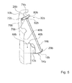
- FIGS. 4 and 5 show a second embodiment of an aircraft seat holding device according to the invention.
- the aircraft seat holding device is part of an aircraft seat 38b only partially shown.
- the aircraft seat 38b has a backrest 10b.
- the backrest 10b has a rear side 40b.
- the rear side 40b of the backrest 10b is arranged facing a further aircraft seat behind the aircraft seat 38b.
- the aircraft seat 38b further comprises a literature pocket 44b.
- the literature bag 44b is disposed in an area behind a dining table in its unused state. In this case, the literature pocket 44b has an opening 46b, via which literature and other objects can be introduced into the literature pocket 44b.
- the aircraft seat holding device includes an aircraft seat carrier unit 12b.
- the aircraft seat carrier unit 12b is designed as a backrest bridge.
- the aircraft seat carrier unit 12b is formed substantially the same as in the first embodiment of the FIGS. 1 to 3 ,
- the aircraft seat holding apparatus further comprises a fixing unit 14b.
- the attachment unit 14b is provided to replace a PED 16b and operable to attach to the backrest 10b.
- the fastening unit 14b comprises a movable retaining element 18b.
- the movable holding element 18b is integrated in a central region 52b of the aircraft seat carrier unit 12b and is identical to the holding element of the first embodiment of FIGS FIGS. 1 to 3 ,
- the aircraft seat holding device has a receiving unit 28b.
- the receiving unit 28b is designed differently in contrast to the first embodiment.
- the receiving unit 28b is designed as a pivotable tab.
- the receiving unit 28b is arranged at a fixed position on the backrest 10b.
- the receiving unit 28b is in particular not adjustable in height to the backrest.
- the aircraft seat holding device has a hinge 72b.
- the hinge 72b is fixedly mounted on the back 40b of the seatback 10b. In this case, the hinge 72b and thereby the receiving unit 28b is arranged in a region 30b above the aircraft seat carrier unit 12b.
- the hinge 72b supports the receiving unit 28b at a first upper end, which faces away from the aircraft seat carrier unit 12b in the assembled state.
- the aircraft seat holding device comprises a spring element.
- the spring element is intended to exert a closing force on the receiving unit 28b.
- the spring element is integrated in the hinge 72b.
- the spring element is not shown in detail.
- the spring element is designed as a spiral spring. A spring force of the spring element generates by a coupling with the receiving unit 28b a moment on the receiving unit 28b.
- the backrest 10b forms a recess 76b for receiving the receiving unit 28b.
- the recess 76b is inserted in the back 40b of the backrest 10b.
- the receiving unit 28b is arranged in the recess 76b. In the stowage position, the receiving unit 28b is arranged completely in the recess 76b.
- the receiving unit 28b comprises a support element 82b for connecting PEDs 16b of different sizes.
- the support member 82b is provided to support PEDs 16b of various sizes on the receiving unit 28b.
- the support member 82b is disposed on the inner side 74b of the receiving unit 28b.
- the support member 82b is formed as a survey.
- the support member 82b formed as a projection extends away from the inner side 74b.
- a PED 16b can now be supported on a side surface 78b of the support element 82b directed in the direction of the first end of the receiving unit 28b or on a side surface 80b of the support element 82b directed in the direction of the second end of the receiving unit 28b.
- the receiving unit 28b is further pivoted out of its stowed position.
- the receiving unit 28b is pivoted against the spring force of the spring element, whereby the spring element presses on the PED 16b and thereby clamps this between the receiving unit 28b and the holding member 18b of the fastening unit 14b.
- the receiving unit 28b is loaded by the spring element, it is possible to dispense with a spring element which would exert a spring force on the retaining element 18b of the fastening unit 14b.
- a large PED 16b for example, 11 inches
- FIG. 5 shows a smaller PED 16b (for example, 9 inches) clamped between the mounting unit 14b and the receiving unit 28b.
Landscapes
- Engineering & Computer Science (AREA)
- Aviation & Aerospace Engineering (AREA)
- Seats For Vehicles (AREA)
Abstract
Description
- Die Erfindung betrifft eine Flugzeugsitzhaltevorrichtung nach dem Oberbegriff des Patentanspruchs 1.
- Es ist bereits eine Flugzeugsitzhaltevorrichtung mit zumindest einer Rückenlehne, mit zumindest einer von einer Rückenlehnenbrücke gebildeten Flugzeugsitzträgereinheit und mit zumindest einer Befestigungseinheit, die dazu vorgesehen ist, in zumindest einem Betriebszustand zumindest ein PED an der Rückenlehne austauschbar und bedienbar zu befestigen, vorgeschlagen worden.
- Die Aufgabe der Erfindung besteht insbesondere darin, eine gattungsgemäße Flugzeugsitzhaltevorrichtung mit verbesserten Eigenschaften hinsichtlich Kosten und einer konstruktiven Einfachheit bereitzustellen. Die Aufgabe wird erfindungsgemäß durch die Merkmale des Patentanspruchs 1 gelöst, während vorteilhafte Ausgestaltungen und Weiterbildungen der Erfindung den Unteransprüchen entnommen werden können.
- Die Erfindung geht aus von einer Flugzeugsitzhaltevorrichtung mit zumindest einer Rückenlehne, mit zumindest einer von einer Rückenlehnenbrücke gebildeten Flugzeugsitzträgereinheit und mit zumindest einer Befestigungseinheit, die dazu vorgesehen ist, in zumindest einem Betriebszustand zumindest ein PED an der Rückenlehne austauschbar und bedienbar zu befestigen.
- Es wird vorgeschlagen, dass die Befestigungseinheit zumindest teilweise in die als Rückenlehnenbrücke gebildete Flugzeugsitzträgereinheit integriert ist. Unter einer "Rückenlehne" soll dabei insbesondere ein Teil eines Flugzeugsitzes verstanden werden, welches einen Rücken eines auf dem Flugzeugsitz sitzenden Passagiers stützt. Die Rückenlehne ist dabei zumindest in einer TTL-Position im Wesentlichen senkrecht zu einer Aufständerebene, auf der der Flugzeugsitz aufgeständert ist, ausgerichtet und ist schwenkbar mit einem Sitzboden des Flugzeugsitzes verbunden. Unter einer "Fahrzeugsitzträgereinheit" soll insbesondere eine Einheit verstanden werden, die in dem montierten Zustand als eine Trägereinheit zumindest einer weiteren Komponente ausgebildet ist. Unter einer "Trägereinheit" soll insbesondere eine Einheit verstanden werden, die in dem montierten Zustand dazu vorgesehen ist, eine Gewichtskraft der weiteren Komponente zumindest teilweise zu tragen. Vorzugsweise ist die Trägereinheit dazu vorgesehen, in dem montierten Zustand auf die Trägereinheit einwirkende Kräfte abzuleiten. Unter einer "Rückenlehnenbrücke" soll insbesondere eine Einheit verstanden werden, die dazu vorgesehen ist, eine Rückenlehne zumindest teilweise zu überbrücken. Insbesondere ist die Rückenlehnenbrücke dazu vorgesehen, zumindest zwei, vorzugsweise seitliche Begrenzungen der Rückenlehne miteinander zu verbinden. Insbesondere ist die Rückenlehnenbrücke in einem oberen Bereich der Rückenlehne angeordnet. Unter einem "oberen Bereich" der Rückenlehne soll insbesondere ein Bereich der Rückenlehne verstanden werden, der in einer aufrechten Stellung des Flugzeugsitzes, vorzugsweise bei einer zumindest im Wesentlichen senkrecht zu dem Boden ausgerichteten Rückenlehnenlängserstreckung, in einem einer Aufständereinheit des Flugzeugsitzes abgewandten Bereich der Rückenlehne angeordnet ist. Insbesondere ist der obere Bereich der Rückenlehne bezüglich einer Rückenlehnenlängsrichtung oberhalb eines Betrags von mehr als 40 %, vorzugsweise von mehr als 50 % und insbesondere von mehr als 55 % der Rückenlehnenlängserstreckung angeordnet. Unter einer "Rückenlehnenlängserstreckung" soll dabei insbesondere eine Haupterstreckung der Rückenlehne verstanden werden, die in einer aufrechten Stellung der Rückenlehne, also der TTL-Position, im Wesentlichen senkrecht zu der Aufständerebene verläuft. Die Rückenlehnenlängserstreckung erstreckt sich dabei von einem ersten unteren Ende der Rückenlehne, an dem die Rückenlehne mit einem Sitzboden gekoppelt ist, bis an ein zweites oberes Ende, an dem die Rückenlehne eine Kopfstütze aufweist. Unter einer "Befestigungseinheit" soll dabei insbesondere eine Einheit verstanden werden, die dazu vorgesehen ist, in zumindest einem Betriebszustand ein PED kraftschlüssig und/oder formschlüssig an der Rückenlehne zu befestigen. Beispielsweise ist die Befestigungseinheit dazu vorgesehen, in zumindest einem Betriebszustand das PED mittels einer Rastverbindung, einer Klemmverbindung und/oder einer Verbindung mittels eines Klettverschlusses zu befestigen. Alternativ sind weitere, einem Fachmann als sinnvoll erscheinende Befestigungsarten denkbar. Insbesondere ist die Befestigungseinheit dazu vorgesehen, in zumindest einem Betriebszustand das PED unter Vermeidung einer Bewegung des PEDs bei Einwirken von durch eine Bedienung des PEDs erzeugten Kräften zu befestigen. Unter "bedienbar befestigen" soll dabei insbesondere verstanden werden, dass der PED in einer solchen Weise an der Befestigungseinheit angebracht ist, dass er von einem auf dem entsprechenden Flugzeugsitz sitzenden Passagier bedient werden kann. Unter "vorgesehen" soll insbesondere speziell ausgelegt und/oder ausgestattet verstanden werden. Darunter, dass ein Objekt zu einer bestimmten Funktion vorgesehen ist, soll insbesondere verstanden werden, dass das Objekt diese bestimmte Funktion in zumindest einem Anwendungs- und/oder Betriebszustand erfüllt und/oder ausführt. Unter "zumindest teilweise integriert" soll dabei insbesondere verstanden werden, dass zumindest ein Teil der Befestigungseinheit, vorteilhaft aber mehr als 50 % der Befestigungseinheit und in einer besonders vorteilhaften Ausgestaltung die komplette Befestigungseinheit in die als Rückenlehnenbrücke ausgebildete Flugzeugsitzträgereinheit integriert ist. Unter einem "PED" soll dabei insbesondere ein mobiles elektronisches Gerät, wie insbesondere ein Tablet-PC, ein Smartphone, ein E-Book-Reader oder ein anderes, dem Fachmann als sinnvoll erscheinendes mobiles elektronisches Gerät verstanden werden. Durch eine erfindungsgemäße Ausgestaltung kann die Befestigungseinheit besonders einfach und vorteilhaft in die Rückenlehne integriert werden. Dadurch kann insbesondere eine einfache Flugzeugsitzhaltevorrichtung bereitgestellt werden.
- Weiter wird vorgeschlagen, dass die Befestigungseinheit wenigstens ein bewegbares Halteelement aufweist, das an die Flugzeugsitzträgereinheit angebunden ist. Unter einem "Halteelement" soll dabei insbesondere ein Element verstanden werden, an dem sich andere Elemente, wie insbesondere ein PED, abstützen können und dadurch gehalten werden. Dabei wird eine Gewichtskraft von dem gehaltenen Element über das Halteelement an die Struktur, an der das Halteelement befestigt ist, wie in diesem Fall insbesondere die als Rückenlehnenbrücke ausgebildete Flugzeugsitzträgereinheit, eingeleitet. Darunter, dass das "Halteelement" beweglich ist", soll dabei insbesondere verstanden werden, dass das Halteelement zumindest zwei Zustände aufweist, in denen es in verschiedenen Stellungen ausgerichtet ist. Dabei ist das Halteelement durch eine Lagerung, wie beispielsweise ein Scharnier, eine Linearführung oder eine andere, dem Fachmann als sinnvoll erscheinende Lagerung in definierten Bewegungsbahnen zu der Flugzeugsitzträgereinheit bewegbar. Dadurch kann die Befestigungseinheit besonders vorteilhaft und einfach benutzbar ausgebildet werden.
- Zudem wird vorgeschlagen, dass das bewegbare Halteelement als eine schwenkbare Klappe ausgebildet ist. Unter einer "schwenkbaren Klappe" soll dabei insbesondere ein Element verstanden werden, das um eine Rotationsachse zu einer Struktur, an der es befestigt ist, wie in diesem Fall insbesondere zu der als Rückenlehnenbrücke ausgebildeten Flugzeugsitzträgereinheit, schwenkbar gelagert ist. Dadurch kann das Halteelement besonders einfach und vorteilhaft ausgebildet werden.
- Des Weiteren wird vorgeschlagen, dass das bewegbare Halteelement zumindest ein Abstützelement aufweist, das dazu vorgesehen ist, ein unteres Ende des PEDs abstützen. Unter einem "Abstützelement" soll dabei insbesondere ein Element verstanden werden, das eine Auflagefläche für ein auf dem Halteelement anzubringendes Element, wie insbesondere ein PED, bereitstellt, wodurch das Element vorteilhaft sicher auf dem Halteelement aufliegen kann. Unter einem "unteren Ende des PEDs" soll dabei insbesondere ein nach unten, in Richtung einer Aufständerebene, auf der der Flugzeugsitz aufgeständert ist, gerichtetes Ende des PEDs verstanden werden. Dabei ist die Bezeichnung unteres Ende jeweils nicht auf ein spezielles Ende des PEDs bezogen, sondern bezieht sich auf ein Ende des PEDs in Bezug auf den Flugzeugsitz. Dadurch kann das Halteelement besonders vorteilhaft zur sicheren Abstützung eines PEDs ausgebildet werden.
- Weiterhin wird vorgeschlagen, dass das bewegbare Halteelement eine Außenkontur ausbildet, die in einem eingeklappten Zustand eben mit einer Außenkontur der Flugzeugsitzträgereinheit verläuft. Unter einer "Außenkontur des Halteelements" soll dabei insbesondere eine Kontur des Halteelements verstanden werden, die das Halteelement nach außen hin, insbesondere in eine von der Rückenlehne abgewandte Richtung, begrenzt. Die Außenkontur bildet dabei vorzugsweise eine Oberfläche, die das Halteelement in Richtung eines hinter der Rückenlehne angeordneten Flugzeugsitzes abschließt und die, von einem auf dem Flugzeugsitz sitzenden Passagier gesehen, erfasst werden kann. Unter einer "Außenkontur der Flugzeugsitzträgereinheit" soll dabei insbesondere eine Kontur der Flugzeugsitzträgereinheit verstanden werden, die die Flugzeugsitzträgereinheit nach außen hin, insbesondere in eine von der Rückenlehne abgewandte Richtung begrenzt. Die Außenkontur bildet dabei vorzugsweise eine Oberfläche, die die Flugzeugsitzträgereinheit in Richtung eines hinter der Rückenlehne angeordneten Flugzeugsitzes abschließt und die, von einem auf dem Flugzeugsitz sitzenden Passagier gesehen, erfasst werden kann. Darunter, dass die "Außenkonturen eben verlaufen", soll dabei insbesondere verstanden werden, dass die Außenkontur der Flugzeugsitzträgereinheit und die Außenkontur des Halteelements in einem Übergang zwischen der Flugzeugsitzträgereinheit und dem Halteelement in einer Ebene verlaufen und in dem Übergang zwischen der Flugzeugsitzträgereinheit und dem Halteelement insbesondere kein Absatz vorhanden ist. Unter einem "eingeklappten Zustand des Halteelements" soll dabei insbesondere eine Stellung des Halteelements verstanden werden, in der kein Element von ihm gehalten wird und das Halteelement möglichst platzsparend an und/oder in der Flugzeugsitzträgereinheit angeordnet ist. Der eingeklappte Zustand des Halteelements bildet eine Verstaustellung der Befestigungseinheit aus. Dadurch kann das Halteelement besonders vorteilhaft in die Flugzeugsitzträgereinheit integriert werden und insbesondere störende Kanten und Absätze in einer Außenkontur der Rückenlehne können vermieden werden.
- Ferner wird vorgeschlagen, dass die Flugzeugsitzträgereinheit eine Tasche ausbildet, in der das bewegliche Halteelement in einem eingeklappten Zustand angeordnet ist. Dadurch kann das Halteelement vorteilhaft platzsparend in der Flugzeugsitzträgereinheit angeordnet werden.
- Es wird weiter vorgeschlagen, dass sich das Halteelement lediglich über einen Teil der als Rückenlehnenbrücke ausgebildeten Flugzeugsitzträgereinheit erstreckt. Darunter, dass sich das "Halteelement lediglich über einen Teil der als Rückenlehnenbrücke ausgebildeten Flugzeugsitzträgereinheit erstreckt", soll dabei insbesondere verstanden werden, dass sich das Halteelement insbesondere in einer Querrichtung nur zu einem Teil der als Rückenlehnenbrücke ausgebildeten Flugzeugsitzträgereinheit erstreckt. Dadurch kann das Halteelement besonders vorteilhaft platzsparend ausgebildet werden.
- Weiter wird vorgeschlagen, dass die Flugzeugsitzhaltevorrichtung zumindest eine Aufnahmeeinheit zur Befestigung eines oberen Endes des PEDs aufweist. Unter einer "Aufnahmeeinheit" soll dabei insbesondere eine Einheit verstanden werden, die zumindest ein Kraft- und/oder Formschlusselement umfasst, mittels dessen das PED an der Rückenlehne befestigt werden kann. Unter einem "oberen Ende des PEDs" soll dabei insbesondere ein nach oben, von der Aufständerebene, auf der der Flugzeugsitz aufgeständert ist, abgewandtes Ende des PEDs verstanden werden. Dabei ist die Bezeichnung oberes Ende jeweils nicht auf ein spezielles Ende des PEDs bezogen, sondern bezieht sich auf ein Ende des PEDs in Bezug auf den Flugzeugsitz. Dadurch kann das PED besonders vorteilhaft in der Flugzeugsitzhaltevorrichtung befestigt werden.
- Ferner wird vorgeschlagen, dass die Aufnahmeeinheit zur Befestigung des oberen Endes des PEDs in einem Bereich oberhalb der als Rückenlehnenbrücke ausgebildeten Flugzeugsitzträgereinheit angeordnet ist. Unter einem "Bereich oberhalb der als Rückenlehnenbrücke ausgebildeten Flugzeugsitzträgereinheit" soll dabei insbesondere ein Bereich verstanden werden, der, von der als Rückenlehne ausgebildeten Flugzeugsitzträgereinheit gesehen, in einer Richtung, die von der Aufständerebene abgewandt ist, angeordnet ist. Der Bereich oberhalb der Flugzeugsitzträgereinheit ist dabei von einer Rückseite der Rückenlehne oder einer Rückseite einer Kopfstütze des Flugzeugsitzes gebildet. Dadurch kann die Aufnahmeeinheit besonders vorteilhaft zur Anbringung eines PEDs angeordnet werden.
- Es wird weiterhin vorgeschlagen, dass die Aufnahmeeinheit als eine schwenkbare Lasche ausgebildet ist. Unter einer "schwenkbaren Lasche" soll dabei insbesondere ein Element verstanden werden, das mit einem ersten Ende schwenkbar mit der Rückenlehne verbunden ist. Dabei bildet die als schwenkbare Lasche ausgebildete Aufnahmeeinheit an einem zweiten Ende vorteilhaft ein Formschlusselement aus, das zur Aufnahme des oberen Endes des PEDs vorgesehen ist. Dadurch kann die Aufnahmeeinheit besonders einfach und vorteilhaft ausgebildet werden.
- Weiter wird vorgeschlagen, dass die Aufnahmeeinheit zumindest ein Abstützelement aufweist, das dazu vorgesehen ist, PEDs verschiedener Größen an der Aufnahmeeinheit abzustützen. Dabei stützen sich unterschiedlich große PEDs vorteilhaft an unterschiedlichen Seitenflächen des Abstützelements ab. Grundsätzlich wäre es auch denkbar, dass sich das PED dabei zusätzlich an einer Rückseite der Rückenlehne abstützt. Dadurch können vorteilhaft einfach PEDs verschiedener Größen von der Aufnahmeeinheit aufgenommen werden.
- Es wird weiter vorgeschlagen, dass das bewegbare Halteelement zumindest eine Ausnehmung aufweist, die sich von einem angebundenen Ende aus erstreckt. Dadurch können vorteilhaft weitere Elemente, wie insbesondere ein Arretiermechanismus für einen anklappbaren Esstisch, in die Flugzeugsitzträgereinheit integriert werden, die auch bedienbar sind, wenn das bewegbare Halteelement in einem eingeklappten Zustand ist.
- Es wird weiter vorgeschlagen, dass die Flugzeugsitzhaltevorrichtung zumindest eine Verriegelungseinheit aufweist, die das bewegbare Halteelement in einem eingeklappten Zustand fixiert. Unter einer "Verriegelungseinheit" soll dabei insbesondere eine Einheit verstanden werden, die zumindest in dem eingeklappten Zustand zumindest eine definierte Schließkraft auf das Halteelement ausübt, die das Halteelement in dem eingeklappten Zustand hält. Grundsätzlich ist es auch denkbar, dass die Verriegelungseinheit von einem federbelasteten Element, wie beispielsweise von einem kugelförmigen Druckstück, ausgebildet ist, das beispielsweise in dem Halteelement angeordnet ist, über eine Außenfläche des Halteelements hinausragt und in einem eingeklappten Zustand des Halteelements in eine Ausnehmung, die in die Flugzeugsitzträgereinheit eingebracht ist, einrastet und das Halteelement so zu der Flugzeugsitzträgereinheit fixiert. Grundsätzlich ist es natürlich auch denkbar, dass eine Anordnung des Druckstücks und der Ausnehmung in den entsprechenden Elementen umgekehrt ist. Dabei müsste zur Verstellung des Halteelements aus dem eingeklappten Zustand eine Kraft auf das Halteelement ausgeübt werden, durch die das federbelastete Element aus der Ausnehmung ausgelenkt wird und das Halteelement so freigibt. Grundsätzlich ist es auch denkbar, dass die Verriegelungseinheit auf eine andere, dem Fachmann als sinnvoll erscheinende Weise ausgebildet ist, wie beispielsweise durch eine Rastnase oder einen Push-Push-Verschluss, wie beispielsweise einen Druckmagnetschnepper. Dadurch kann in dem eingeklappten Zustand ein unbeabsichtigtes Bewegen des Halteelements in einen geöffneten Zustand verhindert werden.
- Ferner wird vorgeschlagen, dass die Flugzeugsitzhaltevorrichtung zumindest ein Federelement aufweist, das zumindest in einem Betriebszustand eine Schließkraft auf das Halteelement und/oder die Aufnahmeeinheit ausübt. Unter einem "Federelement" soll dabei insbesondere eine Feder, wie beispielsweise eine Spiralfeder, eine Blattfeder, eine Gasdruckfeder oder ein aus einem anderen elastischen Material gebildetes Federelement verstanden werden. Dadurch kann die Verriegelungseinheit besonders vorteilhaft ausgebildet werden und gleichzeitig ein PED in einem in der Befestigungseinheit gehaltenen Zustand zwischen dem Halteelement und dem Aufnahmeeinheit verklemmt werden und so besonders sicher in der Befestigungseinheit angeordnet werden.
- Weiter wird vorgeschlagen, dass die Aufnahmeeinheit in einer Höhe verstellbar ist. Unter "in der Höhe verstellbar" soll dabei insbesondere verstanden werden, dass die gesamte Aufnahmeeinheit zu der Rückenlehne in der Rückenlehnenlängserstreckung verschoben werden kann. Dabei ist die Aufnahmeeinheit vorzugsweise an einer Verbindungsstelle, an der die Aufnahmeeinheit schwenkbar an die Rückenlehne gekoppelt ist, in der Höhe verschiebbar. Zur Höhenverstellung der Aufnahmeeinheit weist die Befestigungseinheit vorzugsweise eine Linearführung auf, mit der die Aufnahmeeinheit gekoppelt ist. Dabei ist die Aufnahmeeinheit vorzugsweise in jede beliebige Stellung in der Linearführung frei verschiebbar und ist dabei vorzugsweise arretierfrei. Dadurch kann die Befestigungseinheit vorteilhaft an verschieden große PEDs angepasst werden und diese jeweils sicher an der Rückenlehne befestigen.
- Die erfindungsgemäße Flugzeugsitzträgereinheit soll hierbei nicht auf die oben beschriebene Anwendung und Ausführungsform beschränkt sein. Insbesondere kann die erfindungsgemäße Flugzeugsitzträgereinheit zu einer Erfüllung einer hierin beschriebenen Funktionsweise eine von einer hierin genannten Anzahl von einzelnen Elementen, Bauteilen und Einheiten abweichende Anzahl aufweisen.
- Weitere Vorteile ergeben sich aus der folgenden Zeichnungsbeschreibung. In der Zeichnung sind zwei Ausführungsbeispiele der Erfindung dargestellt. Die Zeichnung, die Beschreibung und die Ansprüche enthalten zahlreiche Merkmale in Kombination. Der Fachmann wird die Merkmale zweckmäßigerweise auch einzeln betrachten und zu sinnvollen weiteren Kombinationen zusammenfassen.
- Es zeigen:
- Fig. 1
- eine schematische Darstellung eines Teils eines Flugzeugsitzes mit einer erfindungsgemäßen Flugzeugsitzhaltevorrichtung in einem ersten Ausführungsbeispiel und einer Befestigungseinheit in einem geöffneten Zustand,
- Fig. 2
- eine schematische Darstellung der Flugzeugsitzhaltevorrichtung mit einem darin angeordneten PED,
- Fig. 3
- eine Detailansicht einer Flugzeugsitzträgereinheit mit der Befestigungseinheit in einem eingeklappten Zustand,
- Fig. 4
- eine schematische Darstellung einer erfindungsgemäßen Flugzeugsitzhaltevorrichtung in einem zweiten Ausführungsbeispiel mit einem darin angebrachten kleinen PED und
- Fig. 5
- eine schematische Darstellung der erfindungsgemäßen Flugzeugsitzhaltevorrichtung in dem zweiten Ausführungsbeispiel mit einem darin angebrachten größeren PED.
- Die
Figuren 1 bis 3 zeigen ein erstes Ausführungsbeispiel einer erfindungsgemäßen Flugzeugsitzhaltevorrichtung. Die Flugzeugsitzhaltevorrichtung ist Teil eines nur teilweise dargestellten Flugzeugsitzes 38a. Der Flugzeugsitz 38a ist in einem montierten Zustand in einem nicht näher dargestellten Flugzeug aufgeständert. Dazu weist der Flugzeugsitz 38a eine nicht näher dargestellte Aufständereinheit auf, mittels der der Flugzeugsitz 38a auf einer Aufständerebene in dem Flugzeug aufgeständert ist. Die Aufständerebene ist dabei von einem Kabinenboden des Flugzeugs gebildet. Dabei ist der Flugzeugsitz 38a als ein Teil einer nicht näher dargestellten Flugzeugsitzreihe ausgebildet. Die Flugzeugsitzreihe ist dabei von drei nebeneinander angeordneten, gleich ausgebildeten Flugzeugsitzen 38a gebildet. Die Aufständereinheit ist dabei zur gemeinsamen Aufständerung aller Flugzeugsitze 38a einer Flugzeugsitzreihe vorgesehen. Grundsätzlich ist es auch denkbar, dass die Flugzeugsitzreihe eine andere Anzahl an Flugzeugsitzen 38a aufweist oder dass der Flugzeugsitz 38a als ein Einzelsitz ausgebildet ist. Der Flugzeugsitz 38a umfasst einen nicht näher dargestellten Sitzboden, der auf der Aufständereinheit befestigt ist. Der Sitzboden bildet eine Sitzfläche aus, auf der ein Fluggast sitzen kann. Der Flugzeugsitz 38a weist ferner eine Rückenlehne 10a auf. Die Rückenlehne 10a ist mit dem Sitzboden gekoppelt. Die Rückenlehne 10a ist dabei ebenfalls mit der Aufständereinheit gekoppelt. Dabei ist die Rückenlehne 10a in einer aufrechten Stellung, also einer TTL-Position, senkrecht zu der Aufständerebene ausgerichtet. Die Rückenlehne 10a ist vorzugsweise schwenkbar mit dem Sitzboden gekoppelt, wodurch verschiedene Sitzstellungen für den Fluggast realisierbar sind. Die Rückenlehne 10a weist eine Rückseite 40a auf. Die Rückseite 40a der Rückenlehne 10a ist einem hinter dem Flugzeugsitz 38a angeordneten, weiteren Flugzeugsitz zugewandt. Der Flugzeugsitz 38a umfasst einen nicht näher dargestellten schwenkbaren Esstisch, der an der Rückseite 40a der Rückenlehne 10a angeordnet ist. Der schwenkbare Esstisch ist in einem mittleren Bereich 42a der Rückenlehne 10a angeordnet. Der schwenkbare Esstisch ist in einem unbenutzten Zustand an die Rückseite 40a der Rückenlehne 10a angeklappt. Dabei liegt der schwenkbare Esstisch in dem unbenutzten Zustand an der Rückseite 40a der Rückenlehne 10a an und verläuft dabei parallel zu dieser. Weiter umfasst der Flugzeugsitz 38a eine Literaturtasche 44a. Die Literaturtasche 44a ist in einem Bereich hinter dem Esstisch in dessen unbenutztem Zustand angeordnet. Die Literaturtasche 44a ist dazu vorgesehen, dass Literatur in ihr aufbewahrt werden kann. Dabei weist die Literaturtasche 44a eine Öffnung 46a auf, über die Literatur und andere Gegenstände in die Literaturtasche 44a eingeführt werden können. Die Öffnung 46a der Literaturtasche 44a ist dabei oberhalb des Esstisches in dessen unbenutztem Zustand angeordnet. Dadurch kann Literatur in die Literaturtasche 44a eingeführt werden, auch wenn der Esstisch an der Rückseite 40a der Rückenlehne 10a angeklappt ist. Denkbar ist auch, dass der Flugzeugsitz 38a zumindest eine Armlehne (nicht dargestellt) aufweist. - Die Flugzeugsitzhaltevorrichtung umfasst eine Flugzeugsitzträgereinheit 12a. Die Flugzeugsitzträgereinheit 12a ist als eine Rückenlehnenbrücke ausgebildet. Die Flugzeugsitzträgereinheit 12a weist eine Trägerlängserstreckung auf, die im Wesentlichen parallel zu einer von der Rückenlehne 10a aufgespannten Ebene ausgerichtet ist. Zudem ist die Trägerlängserstreckung im Wesentlichen parallel zu dem Sitzboden ausgerichtet. Die Flugzeugsitzträgereinheit 12a ist in dem montierten Zustand fest mit der Rückenlehne 10a verbunden. Die als Rückenlehnenbrücke ausgebildete Flugzeugsitzträgereinheit 12a verbindet eine linke Seite der Rückenlehne 10a mit einer rechten Seite der Rückenlehne 10a. Dabei ist die Flugzeugsitzträgereinheit 12a unmittelbar oberhalb des Esstisches in dem angeklappten Zustand angeordnet. Auf der rechten Seite und der linken Seite der Rückenlehne 10a weist die Flugzeugsitzträgereinheit 12a jeweils einen Anbindungsbereich 48a, 50a auf, in dem die als Rückenlehnenbrücke ausgebildete Flugzeugsitzträgereinheit 12a jeweils mit der Rückenlehne 10a verbunden ist. Zwischen den beiden Anbindungsbereichen 48a, 50a weist die Flugzeugsitzträgereinheit 12a einen Mittelbereich 52a auf. Der Mittelbereich 52a ist mit den Anbindungsbereichen 48a, 50a verbunden. Dabei ist der Mittelbereich 52a vorzugsweise einstückig mit den Anbindungsbereichen 48a, 50a ausgebildet. Der Mittelbereich 52a ist dabei beabstandet zu der Rückseite 40a der Rückenlehne 10a angeordnet. Ein Raum, der zwischen dem Mittelbereich 52a der Flugzeugsitzträgereinheit 12a und der Rückseite 40a der Rückenlehne 10a aufgespannt wird, bildet die Öffnung 46a der Literaturtasche 44a. Die Flugzeugsitzträgereinheit 12a umfasst weiter einen Arretiermechanismus 54a zur Sicherung des Esstisches in einem angeklappten Zustand. Der Mittelbereich 52a weist mittig einen Aufnahmebereich 56a für den Arretiermechanismus 54a auf. Grundsätzlich ist es auch denkbar, dass der Aufnahmebereich 56a für den Arretiermechanismus 54a auch außermittig in dem Mittelbereich 52a angeordnet ist. Dabei ist der Arretiermechanismus 54a in den Zeichnungen nicht näher dargestellt und soll im Folgenden auch nicht näher erläutert werden, da er aus dem Stand der Technik ausreichend bekannt ist.
- Die Flugzeugsitzhaltevorrichtung umfasst weiter eine Befestigungseinheit 14a. Die Befestigungseinheit 14a ist dazu vorgesehen, ein PED 16a austauschbar und bedienbar an der Rückenlehne 10a zu befestigen. Ein PED 16a ist dabei beispielsweise als ein Tablet-Computer oder ein Smartphone ausgebildet. Dabei ist das PED 16a mittels der Befestigungseinheit 14a so an der Rückenlehne 10a angebracht, dass ein Flugzeugpassagier, der auf dem entsprechenden, hinter dem Flugzeugsitz 38a mit der Befestigungseinheit 14a angeordneten Flugzeugsitz 38a sitzt, das PED 16a vorteilhaft einfach bedienen kann. Die Befestigungseinheit 14a ist dabei in die Flugzeugsitzträgereinheit 12a integriert. Die Befestigungseinheit 14a umfasst ein bewegbares Halteelement 18a. Das bewegbare Halteelement 18a ist in die Flugzeugsitzträgereinheit 12a integriert. Das bewegbare Halteelement 18a weist einen eingeklappten Zustand und einen geöffneten Zustand auf. In dem eingeklappten Zustand ist das bewegbare Halteelement 18a möglichst platzsparend an der Flugzeugsitzträgereinheit 12a angeordnet. In dem eingeklappten Zustand kann das PED 16a nicht von dem Halteelement 18a gehalten werden. In dem geöffneten Zustand ist das bewegliche Halteelement 18a ausgefahren und das PED 16a kann von dem Halteelement 18a gehalten werden. Das bewegbare Halteelement 18a ist dabei als eine schwenkbare Klappe ausgebildet. Dabei ist das Halteelement 18a an einem ersten, angebundenen Ende 34a schwenkbar mit der Flugzeugsitzträgereinheit 12a gekoppelt. An dem ersten, angebundenen Ende 34a weist das bewegbare Halteelement 18a dabei eine Ausnehmung 32a auf. Die Ausnehmung 32a ist dabei mittig in dem bewegbaren Halteelement 18a angeordnet. Die Ausnehmung 32a weist dabei eine Kontur auf, die einer Kontur des Aufnahmebereichs 56a des Arretiermechanismus 54a entspricht. In dem eingeklappten Zustand des bewegbaren Halteelements 18a umschließt das Halteelement 18a den Aufnahmebereich 56a des Arretiermechanismus 54a in drei Richtungen, gibt den Arretiermechanismus 54a aber nach hinten frei. Dadurch kann der Arretiermechanismus 54a sowohl in dem eingeklappten Zustand als auch in dem geöffneten Zustand des Halteelements 18a von einem Fluggast betätigt werden.
- Zur schwenkbaren Lagerung des als schwenkbare Klappe ausgebildeten bewegbaren Halteelements 18a umfasst die Befestigungseinheit 14a ein Scharnier 58a. Das Scharnier 58a ist von dem bewegbaren Halteelement 18a und der Flugzeugsitzträgereinheit 12a gebildet. Ein halteelementseitiger Teil des Scharniers 58a ist von einstückig mit dem Halteelement 18a ausgebildeten Stiftelementen gebildet. Dabei ist im Bereich des ersten angebundenen Endes 34a des Halteelements 18a an Seitenflächen, die in montiertem Zustand den Anbindungsbereichen 48a, 50a der Flugzeugsitzträgereinheit 12a zugewandt sind, jeweils ein Stiftelement angeordnet, das sich in Richtung der Anbindungsbereiche 48a, 50a der Flugzeugsitzträgereinheit 12a erstreckt. Auf innen liegenden Seitenflächen, die die Ausnehmung 32a des Halteelements 18a bilden, ist fluchtend zu den anderen Stiftelementen ebenfalls jeweils ein Stiftelement angeordnet. Die beiden innen liegenden Stiftelemente erstrecken sich dabei von der jeweiligen Seitenfläche der Ausnehmung 32a nach innen, in montiertem Zustand in Richtung des Aufnahmebereichs 56a des Arretiermechanismus 54a. Alle Stiftelemente, die in den Zeichnungen nicht näher dargestellt sind, liegen in einer Flucht und bilden den halteelementseitigen Teil des Scharniers 58a aus. Der Teil des Scharniers 58a, der von der Flugzeugsitzträgereinheit 12a gebildet ist, ist von Aufnahmelöchern gebildet, in die die Stifte des Halteelements 18a in montiertem Zustand eingreifen. Die Aufnahmelöcher sind dabei in eine Außenfläche des Aufnahmebereichs 56a des Arretiermechanismus 54a und in nach innen gerichteten Seitenflächen der Anbindungsbereiche 48a, 50a der Flugzeugsitzträgereinheit 12a eingebracht. Die Aufnahmelöcher weisen dabei jeweils einen kreisrunden Querschnitt auf. Die Aufnahmelöcher sind dabei an einem unteren Ende der Flugzeugsitzträgereinheit 12a angeordnet, das dem Esstisch in einem eingeklappten Zustand des Esstisches zugewandt ist. Die Stiftelemente des Scharniers 58a können in den Aufnahmelöchern rotieren, wodurch sich das Halteelement 18a zu der Flugzeugsitzträgereinheit 12a schwenken lässt. Zur Montage wird das Halteelement 18a an die Flugzeugsitzträgereinheit 12a herangeführt und die Stifte des Scharniers 58a werden durch Aufbringen einer Montagekraft werkzeugfrei in die Aufnahmelöcher des Scharniers 58a gebracht. Dadurch kann das Halteelement 18a vorteilhaft werkzeugfrei und einfach an die Flugzeugsitzträgereinheit 12a montiert werden. Zum Demontieren des Halteelements 18a von der Flugzeugsitzträgereinheit 12a muss eine ausreichend große Demontagekraft auf das Halteelement 18a ausgeübt werden, sodass sich die Stiftelemente des Scharniers 58a aus den Aufnahmelöchern des Scharniers 58a lösen. Dadurch kann das Halteelement 18a einfach und werkzeugfrei ausgetauscht werden. Grundsätzlich wäre es dabei auch denkbar, dass weitere Scharniere und/oder Elemente sowie anders ausgestaltete Scharniere zur Anbindung des Halteelements 18a verwendet werden.
- Das bewegbare Halteelement 18a umfasst ein Abstützelement 20a. Das Abstützelement 20a ist dazu vorgesehen, eine Abstützfläche für das PED 16a bereitzustellen. Ein unteres Ende des PEDs 16a stützt sich dabei in einem Zustand, in dem das PED 16a in der Befestigungseinheit 14a angeordnet ist, an der Abstützfläche des Abstützelements 20a ab. Das Abstützelement 20a ist dabei als eine Erhebung ausgebildet. Das Abstützelement 20a ist dabei auf einer Innenseite des Halteelements 18a angeordnet, die in dem eingeklappten Zustand des Halteelements 18a der Rückenlehne 10a zugewandt ist. Grundsätzlich ist es auch denkbar, dass das Abstützelement 20a anders, beispielsweise als eine Vertiefung ausgebildet ist. Eine Außenkontur 22a des Halteelements 18a, die in montiertem Zustand von der Rückenlehne 10a abgewandt ist, verläuft in eingeklapptem Zustand des Halteelements 18a eben zu einer Außenkontur 24a der Flugzeugsitzträgereinheit 12a. Dadurch bildet die Flugzeugsitzträgereinheit 12a zusammen mit dem Halteelement 18a in einem eingeklappten Zustand des Halteelements 18a eine ebene Außenkontur aus. Dabei sind insbesondere keine störenden Kanten und Höhenunterschiede zwischen den Außenkonturen 22a, 24a des Halteelements 18a und der Flugzeugsitzträgereinheit 12a vorhanden.
- Die Flugzeugsitzträgereinheit 12a weist eine Tasche 26a auf, in der das bewegliche Halteelement 18a in seinem eingeklappten Zustand angeordnet ist. Die Tasche 26a ist dabei in dem Mittelbereich 52a der Flugzeugsitzträgereinheit 12a angeordnet. Die Tasche 26a erstreckt sich dabei von dem einen Anbindungsbereich 48a der Flugzeugsitzträgereinheit 12a bis zu dem anderen Anbindungsbereich 50a der Flugzeugsitzträgereinheit 12a. Der Aufnahmebereich 56a des Arretiermechanismus 54a ist in der Tasche 26a der Flugzeugsitzträgereinheit 12a angeordnet. Dabei begrenzt der Aufnahmebereich 56a die Tasche 26a der Flugzeugsitzträgereinheit 12a. Seitlich ist die Tasche 26a von den Anbindungsbereichen 48a, 50a der Flugzeugsitzträgereinheit 12a begrenzt. Das Halteelement 18a erstreckt sich in einem montierten Zustand lediglich über einen Teil der als Rückenlehnenbrücke ausgebildeten Flugzeugsitzträgereinheit 12a. Das Halteelement 18a erstreckt sich dabei zwischen den beiden Anbindungsbereichen 48a, 50a der Flugzeugsitzträgereinheit 12a.
- Zur Befestigung eines oberen Endes des PEDs 16a weist die Flugzeugsitzhaltevorrichtung eine Aufnahmeeinheit 28a auf. Die Aufnahmeeinheit 28a ist dazu vorgesehen, das obere Ende des PEDs 16a an der Rückenlehne 10a zu fixieren und so das PED 16a sicher in der Flugzeugsitzhaltevorrichtung zu befestigen. Dabei ist die Aufnahmeeinheit 28a zur Befestigung des oberen Endes des PEDs 16a in einem Bereich 30a oberhalb der als Rückenlehnenbrücke ausgebildeten Flugzeugsitzträgereinheit 12a angeordnet. Dabei ist die Aufnahmeeinheit 28a als schwenkbare Lasche ausgebildet. An einem ersten Ende ist die Aufnahmeeinheit 28a schwenkbar mit der Rückenlehne 10a gekoppelt. An einem zweiten Ende weist die als schwenkbare Lasche ausgebildete Aufnahmeeinheit 28a ein Formschlusselement 60a auf. Das Formschlusselement 60a ist als ein Haken ausgebildet. Das als Haken ausgebildete Formschlusselement 60a erstreckt sich dabei an dem zweiten vorderen Ende in einem montierten Zustand nach unten in Richtung der Befestigungseinheit 14a. Dabei ist die Aufnahmeeinheit 28a in einer Höhe verstellbar. Dazu weist die Flugzeugsitzhaltevorrichtung eine Linearführung 62a auf. Die Linearführung 62a umfasst ein erstes Führungselement 64a. Das erste Führungselement 64a ist als eine Schiene ausgebildet. Das als Schiene ausgebildete erste Führungselement 64a ist fest an der Rückseite 40a der Rückenlehne 10a angeordnet. Das erste Führungselement 64a ist dabei in dem Bereich 30a oberhalb der als Rückenlehnenbrücke ausgebildeten Flugzeugsitzträgereinheit 12a angeordnet. Die Linearführung 62a umfasst ein zweites Führungselement 66a. Das zweite Führungselement 66a ist linear verschiebbar mit dem ersten, als Schiene ausgebildeten Führungselement 64a gekoppelt. Das zweite Führungselement 66a ist formschlüssig mit dem ersten Führungselement 64a verbunden. Das zweite Führungselement 66a kann dabei entlang einer Verschiebeachse 68a des ersten Führungselements 64a zu dem ersten Führungselement 64a verschoben werden. Die Verschiebeachse 68a des ersten Führungselements 64a ist dabei parallel zu einer Rückenlehnenlängserstreckung ausgerichtet. Dadurch lässt sich das zweite Führungselement 66a in einer Höhe zu der Rückenlehne 10a verschieben. Das erste Ende der Aufnahmeeinheit 28a ist schwenkbar mit dem zweiten Führungselement 66a verbunden. Dazu weist die Aufnahmeeinheit 28a ein Scharnier 70a auf, das die Aufnahmeeinheit 28a schwenkbar mit dem zweiten Führungselement 66a koppelt. Durch die in der Höhe verschiebbare Aufnahmeeinheit 28a können verschieden große PEDs 16a einfach mittels der Flugzeugsitzhaltevorrichtung an der Rückenlehne 10a angebracht werden.
- Weiter umfasst die Flugzeugsitzhaltevorrichtung eine Verriegelungseinheit 36a. Die Verriegelungseinheit 36a ist dazu vorgesehen, das bewegbare Halteelement 18a in dem eingeklappten Zustand zu fixieren. Die Verriegelungseinheit 36a hält das Halteelement 18a mittels einer Schließkraft in dem eingeklappten Zustand. Dazu umfasst die Verriegelungseinheit 36a ein nicht näher dargestelltes Federelement. Das Federelement ist dabei in die Flugzeugsitzträgereinheit 12a integriert und von außen nicht zu sehen. Das Federelement ist mit dem Halteelement 18a gekoppelt. Dabei übt das Federelement eine Federkraft auf das Halteelement 18a aus, welche das Halteelement 18a mit seinem zweiten Ende, an dem das Abstützelement 20a angeordnet ist, in Richtung der Rückenlehne 10a drückt. Die Federkraft des Federelements bildet dabei die Schließkraft der Verriegelungseinheit 36a aus. Dadurch wird das Halteelement 18a von dem Federelement in seinen eingeklappten Zustand gedrückt. Um das Halteelement 18a aus seinem eingeklappten Zustand in seinen geöffneten Zustand zu bewegen, muss das Halteelement gegen die Federkraft, die das Federelement auf das Halteelement 18a ausübt, bewegt werden. In einem Zustand, in dem ein PED 16a auf dem Halteelement 18a aufliegt, drückt die Schließkraft des Federelements das PED 16a nach oben. Ist das PED 16a mit seinem oberen Ende in der Aufnahmeeinheit 28a angeordnet, klemmt das Federelement das PED 16a durch die Federkraft zwischen dem Halteelement 18a und der Aufnahmeeinheit 28a ein, wodurch das PED 16a sicher an der Rückenlehne angeordnet ist.
- Will ein Passagier ein PED 16a an der Flugzeugsitzhaltevorrichtung anbringen, muss er zunächst das Halteelement 18a der Befestigungseinheit 14a gegen die Schließkraft des Federelements aus der eingeklappten Stellung heraus bewegen. Nun kann der Passagier das PED 16a mit dem unteren Ende auf das Abstützelement 20a des Halteelements 18a auflegen. Nun kann der Passagier die Aufnahmeeinheit 28a mittels der Linearführung 62a in der Höhe so ausrichten, dass die Aufnahmeeinheit 28a das obere Ende des PEDs 16a mit seinem Formschlusselement 60a umgreifen kann. Er schwenkt die als schwenkbare Lasche ausgebildete Aufnahmeeinheit 28a nach unten, sodass das obere Ende des PEDs 16a in dem Formschlusselement 60a der Aufnahmeeinheit 28a angeordnet ist. Mittels einer nicht näher dargestellten Arretierung kann die Aufnahmeeinheit 28a in einer Stellung, in der die Aufnahmeeinheit 28a das PED 16a mit seinem Formschlusselement 60a teilweise umschließt, arretiert werden. Durch die Schließkraft der Federeinheit und die Arretierung der Aufnahmeeinheit 28a wird das PED 16a zwischen dem Halteelement 18a und der verriegelten Aufnahmeeinheit 28a eingeklemmt und so bedienbar und gegen ein Herausfallen gesichert in der Flugzeugsitzhaltevorrichtung und dadurch an der Rückenlehne 10a des Flugzeugsitzes 38a angebracht. Grundsätzlich ist es dabei denkbar, dass Bereiche, in denen das PED 16a auf dem Halteelement 18a, der Aufnahmeeinheit 28a und/oder auf der Rückseite 40a der Rückenlehne 10a aufliegt, durch eine Beschichtung, eine Beflockung, eine Beklebung oder durch eine Verwendung eines weichen Materials besonders vorteilhaft und schonend für das PED 16a ausgebildet sind.
- In
Fig. 4 und5 ist ein weiteres Ausführungsbeispiel der Erfindung gezeigt. Die nachfolgenden Beschreibungen und die Zeichnungen beschränken sich im Wesentlichen auf die Unterschiede zwischen den beiden Ausführungsbeispielen, wobei bezüglich gleich bezeichneter Bauteile, insbesondere in Bezug auf Bauteile mit gleichen Bezugszeichen, grundsätzlich auch auf die Zeichnungen und/oder die Beschreibung des anderen Ausführungsbeispiels, insbesondere derFig. 1 bis 3 , verwiesen werden kann. Zur Unterscheidung der Ausführungsbeispiele ist der Buchstabe a den Bezugszeichen des Ausführungsbeispiels inFig. 1 bis 3 nachgestellt. In dem Ausführungsbeispiel derFig. 4 und5 ist der Buchstabe a durch den Buchstaben b ersetzt. - Die
Figuren 4 und5 zeigen ein zweites Ausführungsbeispiel einer erfindungsgemäßen Flugzeugsitzhaltevorrichtung. Die Flugzeugsitzhaltevorrichtung ist Teil eines nur teilweise dargestellten Flugzeugsitzes 38b. Der Flugzeugsitz 38b weist eine Rückenlehne 10b auf. Die Rückenlehne 10b weist eine Rückseite 40b auf. Die Rückseite 40b der Rückenlehne 10b ist einem hinter dem Flugzeugsitz 38b angeordneten, weiteren Flugzeugsitz zugewandt. Weiter umfasst der Flugzeugsitz 38b eine Literaturtasche 44b. Die Literaturtasche 44b ist in einem Bereich hinter einem Esstisch in dessen unbenutztem Zustand angeordnet. Dabei weist die Literaturtasche 44b eine Öffnung 46b auf, über die Literatur und andere Gegenstände in die Literaturtasche 44b eingeführt werden können. Die Flugzeugsitzhaltevorrichtung umfasst eine Flugzeugsitzträgereinheit 12b. Die Flugzeugsitzträgereinheit 12b ist als eine Rückenlehnenbrücke ausgebildet. Die Flugzeugsitzträgereinheit 12b ist im Wesentlichen gleich ausgebildet wie in dem ersten Ausführungsbeispiel aus denFiguren 1 bis 3 . Die Flugzeugsitzhaltevorrichtung umfasst weiter eine Befestigungseinheit 14b. Die Befestigungseinheit 14b ist dazu vorgesehen, ein PED 16b austauschbar und bedienbar an der Rückenlehne 10b zu befestigen. Die Befestigungseinheit 14b umfasst ein bewegbares Halteelement 18b. Das bewegbare Halteelement 18b ist in einen Mittelbereich 52b der Flugzeugsitzträgereinheit 12b integriert und ist identisch ausgebildet zu dem Halteelement aus dem ersten Ausführungsbeispiel aus denFiguren 1 bis 3 . - Zur Befestigung eines oberen Endes des PEDs 16b weist die Flugzeugsitzhaltevorrichtung eine Aufnahmeeinheit 28b auf. Die Aufnahmeeinheit 28b ist im Gegensatz zu dem ersten Ausführungsbeispiel anders ausgestaltet. Die Aufnahmeeinheit 28b ist als eine schwenkbare Lasche ausgebildet. Dabei ist die Aufnahmeeinheit 28b an einer festen Position an der Rückenlehne 10b angeordnet. Die Aufnahmeeinheit 28b ist dabei insbesondere nicht in einer Höhe zu der Rückenlehne verstellbar. Zur Anbindung der Aufnahmeeinheit 28b an der Rückenlehne 10b weist die Flugzeugsitzhaltevorrichtung ein Scharnier 72b auf. Das Scharnier 72b ist fest auf der Rückseite 40b der Rückenlehne 10b angebracht. Dabei ist das Scharnier 72b und dadurch die Aufnahmeeinheit 28b in einem Bereich 30b oberhalb der Flugzeugsitzträgereinheit 12b angeordnet. Das Scharnier 72b lagert die Aufnahmeeinheit 28b an einem ersten oberen Ende, das in montiertem Zustand der Flugzeugsitzträgereinheit 12b abgewandt ist. Ein zweites unteres Ende der Aufnahmeeinheit 28b, das in montiertem Zustand der Flugzeugsitzträgereinheit 12b zugewandt ist, ist mittels des Scharniers 72b von der Rückseite 40b der Rückenlehne 10b weg schwenkbar. Die Flugzeugsitzhaltevorrichtung umfasst ein Federelement. Das Federelement ist dazu vorgesehen, eine Schließkraft auf die Aufnahmeeinheit 28b auszuüben. Dazu ist das Federelement in das Scharnier 72b integriert. Das Federelement ist dabei nicht näher dargestellt. Das Federelement ist als eine Spiralfeder ausgebildet. Eine Federkraft des Federelements erzeugt durch eine Kopplung mit der Aufnahmeeinheit 28b ein Moment auf die Aufnahmeeinheit 28b. Das Moment drückt das zweite Ende der Aufnahmeeinheit 28b mit einer Innenseite 74b in Richtung der Rückseite 40b der Rückenlehne 10b. Dadurch wird die Aufnahmeeinheit 28b von dem Federelement in eine Verstaustellung gedrückt. Die Rückenlehne 10b bildet zur Aufnahme der Aufnahmeeinheit 28b eine Ausnehmung 76b aus. Die Ausnehmung 76b ist in die Rückseite 40b der Rückenlehne 10b eingebracht. Dabei ist die Aufnahmeeinheit 28b in der Ausnehmung 76b angeordnet. In der Verstaustellung ist die Aufnahmeeinheit 28b komplett in der Ausnehmung 76b angeordnet.
- Die Aufnahmeeinheit 28b umfasst zur Anbindung von verschieden großen PEDs 16b ein Abstützelement 82b. Das Abstützelement 82b ist dazu vorgesehen, PEDs 16b verschiedener Größen an der Aufnahmeeinheit 28b abzustützen. Das Abstützelement 82b ist an der Innenseite 74b der Aufnahmeeinheit 28b angeordnet. Das Abstützelement 82b ist dabei als eine Erhebung ausgebildet. Das als Erhebung ausgebildete Abstützelement 82b erstreckt sich von der Innenseite 74b weg. Ein PED 16b kann sich nun, je nach Größe, an einer in Richtung des ersten Endes der Aufnahmeeinheit 28b gerichteten Seitenfläche 78b des Abstützelements 82b oder an einer in Richtung des zweiten Endes der Aufnahmeeinheit 28b gerichteten Seitenfläche 80b des Abstützelements 82b abstützen. Je nach Größe des PEDs 16b wird die Aufnahmeeinheit 28b weiter aus ihrer Verstaustellung herausgeschwenkt. Dabei wird die Aufnahmeeinheit 28b gegen die Federkraft des Federelements aufgeschwenkt, wodurch das Federelement auf das PED 16b drückt und dieses dadurch zwischen der Aufnahmeeinheit 28b und dem Halteelement 18b der Befestigungseinheit 14b einklemmt. In diesem Ausführungsbeispiel, in dem die Aufnahmeeinheit 28b von dem Federelement belastet ist, kann auf ein Federelement, welches eine Federkraft auf das Halteelement 18b der Befestigungseinheit 14b ausüben würde, verzichtet werden. In der
Figur 4 ist ein großes PED 16b (beispielsweise 11 Zoll) gezeigt, das zwischen der Befestigungseinheit 14b und der Aufnahmeeinheit 28b eingeklemmt ist.Figur 5 zeigt ein kleineres PED 16b (beispielsweise 9 Zoll), das zwischen der Befestigungseinheit 14b und der Aufnahmeeinheit 28b eingeklemmt ist. Durch weitere Abstützelemente wäre es denkbar, auch weitere Größen zu befestigen. -
- 10
- Rückenlehne
- 12
- Flugzeugsitzträgereinheit
- 14
- Befestigungseinheit
- 16
- PED
- 18
- Halteelement
- 20
- Abstützelement
- 22
- Außenkontur
- 24
- Außenkontur
- 26
- Tasche
- 28
- Aufnahmeeinheit
- 30
- Bereich
- 32
- Ausnehmung
- 34
- angebundenes Ende
- 36
- Verriegelungseinheit
- 38
- Flugzeugsitz
- 40
- Rückseite
- 42
- mittlerer Bereich
- 44
- Literaturtasche
- 46
- Öffnung
- 48
- Anbindungsbereich
- 50
- Anbindungsbereich
- 52
- Mittelbereich
- 54
- Arretiermechanismus
- 56
- Aufnahmebereich
- 58
- Scharnier
- 60
- Formschlusselement
- 62
- Linearführung
- 64
- erstes Führungselement
- 66
- zweites Führungselement
- 68
- Verschiebeachse
- 70
- Scharnier
- 72
- Scharnier
- 74
- Innenseite
- 76
- Ausnehmung
- 78
- Seitenfläche
- 80
- Seitenfläche
- 82
- Abstützelement
Claims (15)
- Flugzeugsitzhaltevorrichtung mit zumindest einer Rückenlehne (10a; 10b), mit zumindest einer von einer Rückenlehnenbrücke gebildeten Flugzeugsitzträgereinheit (12a; 12b) und mit zumindest einer Befestigungseinheit (14a; 14b), die dazu vorgesehen ist, in zumindest einem Betriebszustand zumindest ein PED (16a; 16b) an der Rückenlehne (10a; 10b) austauschbar und bedienbar zu befestigen, dadurch gekennzeichnet, dass die Befestigungseinheit (14a; 14b) zumindest teilweise in die als Rückenlehnenbrücke gebildete Flugzeugsitzträgereinheit (12a; 12b) integriert ist.
- Flugzeugsitzhaltevorrichtung nach Anspruch 1, dadurch gekennzeichnet, dass die Befestigungseinheit (14a; 14b) wenigstens ein bewegbares Halteelement (18a; 18b) aufweist, das an die Flugzeugsitzträgereinheit (12a; 12b) angebunden ist.
- Flugzeugsitzhaltevorrichtung nach Anspruch 2, dadurch gekennzeichnet, dass das bewegbare Halteelement (18a; 18b) als eine schwenkbare Klappe ausgebildet ist.
- Flugzeugsitzhaltevorrichtung nach Anspruch 2 oder 3, dadurch gekennzeichnet, dass das bewegbare Halteelement (18a; 18b) zumindest ein Abstützelement (20a; 20b) aufweist, das dazu vorgesehen ist, ein unteres Ende des PEDs (16a; 16b) abzustützen.
- Flugzeugsitzhaltevorrichtung zumindest nach Anspruch 2, dadurch gekennzeichnet, dass das bewegbare Halteelement (18a) eine Außenkontur (22a) ausbildet, die in einem eingeklappten Zustand eben mit einer Außenkontur (24a) der Flugzeugsitzträgereinheit (12a) verläuft.
- Flugzeugsitzhaltevorrichtung zumindest nach Anspruch 2, dadurch gekennzeichnet, dass die Flugzeugsitzträgereinheit (12a) eine Tasche (26a) ausbildet, in der das bewegliche Halteelement (18a) in dem eingeklappten Zustand angeordnet ist.
- Flugzeugsitzhaltevorrichtung zumindest nach Anspruch 2, dadurch gekennzeichnet, dass sich das Halteelement (18a; 18b) lediglich über einen Teil der als Rückenlehnenbrücke ausgebildeten Flugzeugsitzträgereinheit (12a; 12b) erstreckt.
- Flugzeugsitzhaltevorrichtung nach einem der vorhergehenden Ansprüche, gekennzeichnet durch zumindest eine Aufnahmeeinheit (28a; 28b) zur Befestigung eines oberen Endes des PEDs (16a; 16b).
- Flugzeugsitzhaltevorrichtung nach Anspruch 8, dadurch gekennzeichnet, dass die Aufnahmeeinheit (28a; 28b) zur Befestigung des oberen Endes des PEDs (16a; 16b) in einem Bereich (30a; 30b) oberhalb der als Rückenlehnenbrücke ausgebildeten Flugzeugsitzträgereinheit (12a; 12b) angeordnet ist.
- Flugzeugsitzhaltevorrichtung nach Anspruch 8 oder 9, dadurch gekennzeichnet, dass die Aufnahmeeinheit (28a; 28b) als eine schwenkbare Lasche ausgebildet ist.
- Flugzeugsitzhaltevorrichtung zumindest nach Anspruch 8, dadurch gekennzeichnet, dass die Aufnahmeeinheit (28b) zumindest ein Abstützelement (82b) aufweist, das dazu vorgesehen ist, PEDs (16b) verschiedener Größen an der Aufnahmeeinheit (28b) abzustützen.
- Flugzeugsitzhaltevorrichtung zumindest nach Anspruch 2, dadurch gekennzeichnet, dass das bewegbare Halteelement (18a) zumindest eine Ausnehmung (32a) aufweist, die sich von einem angebundenen Ende (34a) aus erstreckt.
- Flugzeugsitzhaltevorrichtung nach einem der vorhergehenden Ansprüche, gekennzeichnet durch zumindest eine Verriegelungseinheit (36a), die das bewegbare Halteelement (18a) in einem eingeklappten Zustand fixiert.
- Flugzeugsitzhaltevorrichtung nach einem der vorhergehenden Ansprüche, gekennzeichnet durch zumindest ein Federelement, das zumindest in einem Betriebszustand eine Schließkraft auf das Halteelement (18a) und/oder die Aufnahmeeinheit (28b) ausübt.
- Flugzeugsitz mit einer Flugzeugsitzhaltevorrichtung nach einem der vorhergehenden Ansprüche.
Priority Applications (1)
| Application Number | Priority Date | Filing Date | Title |
|---|---|---|---|
| US14/577,092 US9511862B2 (en) | 2012-12-21 | 2014-12-19 | Aircraft seat holding device |
Applications Claiming Priority (2)
| Application Number | Priority Date | Filing Date | Title |
|---|---|---|---|
| DE102012112942.8A DE102012112942B4 (de) | 2012-12-21 | 2012-12-21 | Flugzeugsitzbefestigungsvorrichtung |
| DE102012112943.6A DE102012112943A1 (de) | 2012-12-21 | 2012-12-21 | Flugzeugsitzträgervorrichtung |
Publications (2)
| Publication Number | Publication Date |
|---|---|
| EP2746158A1 true EP2746158A1 (de) | 2014-06-25 |
| EP2746158B1 EP2746158B1 (de) | 2019-04-24 |
Family
ID=49886736
Family Applications (1)
| Application Number | Title | Priority Date | Filing Date |
|---|---|---|---|
| EP13199144.0A Active EP2746158B1 (de) | 2012-12-21 | 2013-12-20 | Flugzeugsitzhaltevorrichtung |
Country Status (3)
| Country | Link |
|---|---|
| US (1) | US9511862B2 (de) |
| EP (1) | EP2746158B1 (de) |
| TR (1) | TR201910601T4 (de) |
Cited By (19)
| Publication number | Priority date | Publication date | Assignee | Title |
|---|---|---|---|---|
| EP2962937A1 (de) * | 2014-06-30 | 2016-01-06 | Airbus Operations GmbH | Fahrzeugsitz mit integrierter halterung für elektronische vorrichtungen |
| WO2016008890A1 (de) * | 2014-07-15 | 2016-01-21 | Recaro Aircraft Seating Gmbh & Co. Kg | Fahrzeugsitzvorrichtung |
| USD750392S1 (en) | 2013-08-20 | 2016-03-01 | Encore Interiors, Inc. | Aircraft seat |
| WO2016153802A1 (en) * | 2015-03-24 | 2016-09-29 | B/E Aerospace, Inc. | Seat back personal electronic device holder |
| WO2016165982A1 (fr) * | 2015-04-13 | 2016-10-20 | Zodiac Seats France | Dispositif de maintien d'un dispositif portatif pour siege d'aeronef |
| WO2016167720A1 (en) * | 2015-04-13 | 2016-10-20 | Singapore Technologies Aerospace Ltd | Portable electronic device holder |
| WO2016197104A1 (en) * | 2015-06-04 | 2016-12-08 | B/E Aerospace, Inc. | Deployable seatback holder for portable electronic devices |
| CN106573564A (zh) * | 2014-07-24 | 2017-04-19 | 雷诺股份公司 | 用于机动车辆座椅靠背的后托盘、装备有这种托盘的座椅、以及这种座椅的安排 |
| US9630717B2 (en) | 2013-04-26 | 2017-04-25 | Encore Interiors, Inc. | Aircraft seating assembly with reduced spacing |
| US9764844B2 (en) | 2015-04-13 | 2017-09-19 | Encore Seats, Inc. | Aircraft seating assembly |
| US20180072424A1 (en) * | 2016-09-14 | 2018-03-15 | Ford Global Technologies Llc | Electronic device holders |
| US10144515B2 (en) | 2016-04-01 | 2018-12-04 | Encore Seats, Inc. | Aircraft seating assembly and components |
| FR3069502A1 (fr) * | 2017-07-28 | 2019-02-01 | Psa Automobiles Sa | Dossier de siege comportant un support de maintien d’un appareil multimedia dans un vehicule. |
| WO2019202108A1 (de) * | 2018-04-20 | 2019-10-24 | Recaro Aircraft Seating Gmbh & Co. Kg | Flugzeugsitzvorrichtung |
| FR3100768A1 (fr) * | 2019-09-18 | 2021-03-19 | Psa Automobiles Sa | Dispositif de support d’objet à mécanisme de verrouillage |
| IT201900019628A1 (it) * | 2019-10-23 | 2021-04-23 | Geven S P A | Supporto per dispositivi elettronici |
| DE102019135593A1 (de) * | 2019-12-20 | 2021-06-24 | Recaro Aircraft Seating Gmbh & Co. Kg | Flugzeugsitzvorrichtung |
| US20220234739A1 (en) * | 2019-06-27 | 2022-07-28 | Safran Seats Usa Llc | Portable electronic device holder for seat |
| FR3162874A1 (fr) | 2024-05-28 | 2025-12-05 | Airbus Atlantic | Support universel pour tablettes électroniques |
Families Citing this family (22)
| Publication number | Priority date | Publication date | Assignee | Title |
|---|---|---|---|---|
| DE102012210754A1 (de) * | 2012-06-25 | 2014-01-02 | Lufthansa Systems Ag | Sitz für ein Fahrzeug sowie Fahrzeug |
| DE102013113236A1 (de) * | 2013-11-29 | 2015-06-03 | Recaro Aircraft Seating Gmbh & Co. Kg | Flugzeugsitzvorrichtung |
| US9510685B2 (en) * | 2014-05-02 | 2016-12-06 | Steelcase Inc. | Office system telepresence arrangement |
| WO2017048319A1 (en) * | 2015-09-15 | 2017-03-23 | Zodiac Seats Us Llc | Portable electronic device holder for tray tables |
| DE102016210197A1 (de) * | 2016-06-09 | 2017-12-14 | Volkswagen Aktiengesellschaft | Rückenlehne eines Fahrzeugsitzes mit einer Tasche |
| WO2018037256A1 (en) * | 2016-08-25 | 2018-03-01 | Nsv Group Fzco | Vehicle entertainment center assembly with hanger |
| US10220795B2 (en) | 2016-09-08 | 2019-03-05 | Ford Global Technologies, Llc | Device holder and seat with a built-in device holder |
| EP3354570B1 (de) * | 2017-01-31 | 2020-08-12 | Panasonic Intellectual Property Management Co., Ltd. | Schirm und befestigungs-abtrennvorrichtung dafür |
| CN108569220B (zh) * | 2017-03-09 | 2023-04-18 | 福特环球技术公司 | 装置保持器 |
| US10273008B2 (en) * | 2017-03-24 | 2019-04-30 | Ami Industries, Inc. | Inertia reel interface for stowable seats |
| US10065741B1 (en) | 2017-04-11 | 2018-09-04 | B/E Aerospace, Inc. | Illuminated literature pocket for aircraft passenger seat |
| US10562635B2 (en) * | 2018-03-19 | 2020-02-18 | The Boeing Company | Personal device carrier and a passenger seat |
| US10926877B1 (en) | 2018-10-03 | 2021-02-23 | Rockwell Collins, Inc. | Retractable portable electronic device holder |
| US10703482B1 (en) | 2018-12-12 | 2020-07-07 | Rockwell Collins, Inc. | Deployable portable electronic device holder for aircraft seat |
| US10759353B2 (en) * | 2018-12-17 | 2020-09-01 | Fkt Koltuk Sistemleri Uretim Ve Dagitim Sanayi Ve Ticaret Anonim Sirketi | Seat back mobile phone and tablet computer holder |
| US12083962B2 (en) * | 2019-10-31 | 2024-09-10 | Safran Seats Usa Llc | Tape holder for portable electronic device |
| CN113443147A (zh) | 2020-03-24 | 2021-09-28 | 空中客车(中国)企业管理服务有限公司 | 集成式飞行器乘客娱乐设备、飞行器乘客座椅和飞行器 |
| US11979048B2 (en) | 2020-09-18 | 2024-05-07 | B/E Aerospace, Inc. | Inductive charging device holder |
| CN113772102A (zh) * | 2021-08-03 | 2021-12-10 | 中国民用航空总局第二研究所 | 一种航空座椅手机平板支架 |
| KR20230048751A (ko) * | 2021-10-05 | 2023-04-12 | 현대자동차주식회사 | 다기능 휴대품 거치대 및 차량 |
| US12479579B2 (en) * | 2023-03-30 | 2025-11-25 | B/E Aerospace, Inc. | Passenger seat with self-stowing portable electronic device holder |
| US12473089B2 (en) * | 2023-06-28 | 2025-11-18 | B/E Aerospace, Inc. | Portable electronic device holder with socket and rotating partial-cylinder |
Citations (3)
| Publication number | Priority date | Publication date | Assignee | Title |
|---|---|---|---|---|
| WO2007109703A2 (en) * | 2006-03-21 | 2007-09-27 | Be Aerospace , Inc. | Holster for portable ife device |
| US20120120626A1 (en) * | 2010-11-16 | 2012-05-17 | Toyota Boshoku Kabushiki Kaisha | Fixing apparatus for portable device |
| US20120248833A1 (en) * | 2011-04-04 | 2012-10-04 | Be Aerospace, Inc. | Seatback holder for tablet computers |
Family Cites Families (31)
| Publication number | Priority date | Publication date | Assignee | Title |
|---|---|---|---|---|
| US3019050A (en) | 1960-02-15 | 1962-01-30 | Aerotec Ind Inc | Aircraft seats and aircraft seating |
| US3795422A (en) * | 1972-04-04 | 1974-03-05 | Air Specialties Inc | Seat mounted food tray with vanity mirror |
| US4460215A (en) * | 1981-09-30 | 1984-07-17 | The Boeing Company | Folding seat assembly |
| US4836602A (en) | 1988-09-23 | 1989-06-06 | The Boeing Company | Apparatus for storing food and beverages in a passenger seatback |
| US5292174A (en) | 1991-10-22 | 1994-03-08 | Tachi-S Co., Ltd. | Pocket structure in automotive seat |
| DE9310641U1 (de) | 1993-07-16 | 1993-09-02 | Casimir Kast Formteile GmbH & Co, 76593 Gernsbach | Verkleidung für die Rückenlehne von KFZ-Sitzen |
| WO1999035002A1 (en) | 1998-01-02 | 1999-07-15 | Johnson Controls Technology Company | Seat back mounted fold down auto office |
| US6199948B1 (en) | 1998-12-16 | 2001-03-13 | Johnson Controls Technology Company | Interchangeable module system |
| US6702375B1 (en) | 2000-02-29 | 2004-03-09 | Johnson Controls Technology Company | Activity center for a vehicle |
| FR2850339B1 (fr) | 2003-01-28 | 2006-02-24 | Sevic System Ag | Installation video portable comprenant une console electronique genre lecteur video ou console de jeu, et un ecran independant associe |
| FR2855472B1 (fr) | 2003-05-27 | 2005-08-05 | Faurecia Sieges Automobile | Dossier de siege de vehicule muni d'un moniteur de television et siege de vehicule comprenant un tel dossier |
| DE10334595B4 (de) | 2003-07-28 | 2006-03-16 | Grammer Ag | Sitzanordnung für Fahrzeuge |
| US7665804B1 (en) | 2005-02-07 | 2010-02-23 | Vernon Michael Jeffrey | Seat headrest cover for use as a display device |
| US7261266B2 (en) | 2005-03-31 | 2007-08-28 | Satterfield Johnny A | Deployable video arm |
| US8953102B2 (en) | 2006-01-04 | 2015-02-10 | Voxx International Corporation | Vehicle entertainment tablet unit and cradle |
| DE202006003018U1 (de) | 2006-02-23 | 2006-06-08 | Beyer, Katja | Rückseitenverblendung für Fahrzeugsitzlehnen |
| US20080252111A1 (en) | 2007-04-13 | 2008-10-16 | Lear Corporation | Vehicle seat assembly having a modular accessory system and method of making the same |
| US8141948B2 (en) | 2007-05-11 | 2012-03-27 | Audiovox Corporation | Seat back entertainment system |
| US20100213335A1 (en) | 2009-02-20 | 2010-08-26 | Chih-Ming Peng | Swivelable fixing seat |
| US20100244505A1 (en) | 2009-03-31 | 2010-09-30 | Gm Global Technology Operations, Inc. | Video Screen Assembly For Vehicle |
| DE102009052684A1 (de) | 2009-11-11 | 2010-07-15 | Daimler Ag | Verkleidung für eine Rückenlehne eines Fahrzeugsitzes oder dergleichen Sitzanlage für einen Kraftwagen |
| FR2954246B1 (fr) | 2009-12-23 | 2012-05-11 | Faurecia Interieur Ind | Dispositif de maintien d'un appareil electronique dans un vehicule automobile comprenant des elements de retenue formant les coins d'une surface de support |
| EP2569187B1 (de) | 2010-05-14 | 2017-01-25 | Zodiac Seats US LLC | Kupplungseinheit |
| WO2011163440A2 (en) | 2010-06-23 | 2011-12-29 | Weber Aircraft Llc | Seat back assembly |
| DE102010052807A1 (de) | 2010-11-27 | 2011-07-07 | Daimler AG, 70327 | Haltevorrichtung |
| US20120139303A1 (en) | 2010-12-07 | 2012-06-07 | Rik Westerink | Display assembly |
| FR2982218B1 (fr) * | 2011-11-07 | 2013-11-15 | Renault Sas | Tablette de siege formant support d'ecran tactile |
| GB2497323A (en) * | 2011-12-07 | 2013-06-12 | James Shing Hin Lee | High density seating |
| TW201340915A (zh) * | 2012-04-09 | 2013-10-16 | Superalloy Ind Co Ltd | 具有定位平板電子設備的桌面裝置及其座椅 |
| DE102012112943A1 (de) | 2012-12-21 | 2014-06-26 | Recaro Aircraft Seating Gmbh & Co. Kg | Flugzeugsitzträgervorrichtung |
| DE102012112942B4 (de) | 2012-12-21 | 2025-02-06 | Recaro Aircraft Seating Gmbh & Co. Kg | Flugzeugsitzbefestigungsvorrichtung |
-
2013
- 2013-12-20 TR TR2019/10601T patent/TR201910601T4/tr unknown
- 2013-12-20 EP EP13199144.0A patent/EP2746158B1/de active Active
-
2014
- 2014-12-19 US US14/577,092 patent/US9511862B2/en active Active
Patent Citations (3)
| Publication number | Priority date | Publication date | Assignee | Title |
|---|---|---|---|---|
| WO2007109703A2 (en) * | 2006-03-21 | 2007-09-27 | Be Aerospace , Inc. | Holster for portable ife device |
| US20120120626A1 (en) * | 2010-11-16 | 2012-05-17 | Toyota Boshoku Kabushiki Kaisha | Fixing apparatus for portable device |
| US20120248833A1 (en) * | 2011-04-04 | 2012-10-04 | Be Aerospace, Inc. | Seatback holder for tablet computers |
Cited By (39)
| Publication number | Priority date | Publication date | Assignee | Title |
|---|---|---|---|---|
| US9630717B2 (en) | 2013-04-26 | 2017-04-25 | Encore Interiors, Inc. | Aircraft seating assembly with reduced spacing |
| USD750392S1 (en) | 2013-08-20 | 2016-03-01 | Encore Interiors, Inc. | Aircraft seat |
| US20160009394A1 (en) * | 2014-06-30 | 2016-01-14 | Airbus Operations Gmbh | Vehicle seat comprising integrated holder for electronic devices |
| US9457905B2 (en) * | 2014-06-30 | 2016-10-04 | Airbus Operations Gmbh | Vehicle seat comprising integrated holder for electronic devices |
| EP2962937A1 (de) * | 2014-06-30 | 2016-01-06 | Airbus Operations GmbH | Fahrzeugsitz mit integrierter halterung für elektronische vorrichtungen |
| WO2016008890A1 (de) * | 2014-07-15 | 2016-01-21 | Recaro Aircraft Seating Gmbh & Co. Kg | Fahrzeugsitzvorrichtung |
| CN106573564B (zh) * | 2014-07-24 | 2019-05-14 | 雷诺股份公司 | 用于机动车辆座椅靠背的后托盘、机动车辆座椅、以及机动车辆座椅安排结构 |
| CN106573564A (zh) * | 2014-07-24 | 2017-04-19 | 雷诺股份公司 | 用于机动车辆座椅靠背的后托盘、装备有这种托盘的座椅、以及这种座椅的安排 |
| US9776722B2 (en) | 2015-03-24 | 2017-10-03 | B/E Aerospace, Inc. | Seat back personal electronic device holder |
| WO2016153802A1 (en) * | 2015-03-24 | 2016-09-29 | B/E Aerospace, Inc. | Seat back personal electronic device holder |
| CN107646012B (zh) * | 2015-03-24 | 2020-05-22 | Be航空公司 | 座椅靠背个人电子设备夹持器 |
| CN107646012A (zh) * | 2015-03-24 | 2018-01-30 | Be航空公司 | 座椅靠背个人电子设备夹持器 |
| JP2018513806A (ja) * | 2015-04-13 | 2018-05-31 | シンガポール・テクノロジーズ・エアロスペース・リミテッドSingapore Technologies Aerospace Ltd | 携帯型電子機器ホルダ |
| US10597159B2 (en) | 2015-04-13 | 2020-03-24 | ST Engineering Aerospace Ltd. | Portable electronic device holder |
| US9764844B2 (en) | 2015-04-13 | 2017-09-19 | Encore Seats, Inc. | Aircraft seating assembly |
| EP3283376B1 (de) * | 2015-04-13 | 2024-12-25 | Encore Seats, Inc. | Flugzeugsitzeanordnung |
| CN107531327B (zh) * | 2015-04-13 | 2021-03-05 | 祖迪雅克座椅法国公司 | 针对飞机座位的便携式设备的保持装置 |
| CN107531327A (zh) * | 2015-04-13 | 2018-01-02 | 祖迪雅克座椅法国公司 | 针对飞机座位的便携式设备的保持装置 |
| WO2016167720A1 (en) * | 2015-04-13 | 2016-10-20 | Singapore Technologies Aerospace Ltd | Portable electronic device holder |
| US10392114B2 (en) | 2015-04-13 | 2019-08-27 | Encore Seats, Inc. | Aircraft seating assembly |
| US10766620B2 (en) | 2015-04-13 | 2020-09-08 | Safran Seats | Device for supporting a portable device for an aeroplane seat |
| WO2016165982A1 (fr) * | 2015-04-13 | 2016-10-20 | Zodiac Seats France | Dispositif de maintien d'un dispositif portatif pour siege d'aeronef |
| CN107787291A (zh) * | 2015-06-04 | 2018-03-09 | B/E航空公司 | 用于便携式电子设备的可展开的座椅保持器 |
| WO2016197104A1 (en) * | 2015-06-04 | 2016-12-08 | B/E Aerospace, Inc. | Deployable seatback holder for portable electronic devices |
| CN107787291B (zh) * | 2015-06-04 | 2020-10-16 | B/E航空公司 | 用于便携式电子设备的可展开的座椅保持器 |
| US10144515B2 (en) | 2016-04-01 | 2018-12-04 | Encore Seats, Inc. | Aircraft seating assembly and components |
| US10414500B2 (en) * | 2016-09-14 | 2019-09-17 | Ford Global Technologies Llc | Electronic device holders |
| CN107813768A (zh) * | 2016-09-14 | 2018-03-20 | 福特环球技术公司 | 电子装置保持架 |
| US20180072424A1 (en) * | 2016-09-14 | 2018-03-15 | Ford Global Technologies Llc | Electronic device holders |
| FR3069502A1 (fr) * | 2017-07-28 | 2019-02-01 | Psa Automobiles Sa | Dossier de siege comportant un support de maintien d’un appareil multimedia dans un vehicule. |
| WO2019202108A1 (de) * | 2018-04-20 | 2019-10-24 | Recaro Aircraft Seating Gmbh & Co. Kg | Flugzeugsitzvorrichtung |
| US20220234739A1 (en) * | 2019-06-27 | 2022-07-28 | Safran Seats Usa Llc | Portable electronic device holder for seat |
| US12280873B2 (en) * | 2019-06-27 | 2025-04-22 | Safran Seats Usa Llc | Portable electronic device holder for seat |
| FR3100768A1 (fr) * | 2019-09-18 | 2021-03-19 | Psa Automobiles Sa | Dispositif de support d’objet à mécanisme de verrouillage |
| EP3812215A1 (de) | 2019-10-23 | 2021-04-28 | Geven S.p.A. | Halterung für elektronisches gerät |
| IT201900019628A1 (it) * | 2019-10-23 | 2021-04-23 | Geven S P A | Supporto per dispositivi elettronici |
| DE102019135593A1 (de) * | 2019-12-20 | 2021-06-24 | Recaro Aircraft Seating Gmbh & Co. Kg | Flugzeugsitzvorrichtung |
| WO2021123330A1 (de) * | 2019-12-20 | 2021-06-24 | Recaro Aircraft Seating Gmbh & Co. Kg | Flugzeugsitzvorrichtung mit einer haltevorrichtung für einen gegenstand |
| FR3162874A1 (fr) | 2024-05-28 | 2025-12-05 | Airbus Atlantic | Support universel pour tablettes électroniques |
Also Published As
| Publication number | Publication date |
|---|---|
| US20150175265A1 (en) | 2015-06-25 |
| TR201910601T4 (tr) | 2019-08-21 |
| US9511862B2 (en) | 2016-12-06 |
| EP2746158B1 (de) | 2019-04-24 |
Similar Documents
| Publication | Publication Date | Title |
|---|---|---|
| EP2746158B1 (de) | Flugzeugsitzhaltevorrichtung | |
| EP0211248B1 (de) | Sitzverstellung in einem Kraftwagen | |
| DE102011055585B4 (de) | Sitzeinrichtung für ein Kraftfahrzeug | |
| EP3283326B1 (de) | Flugzeugsitzvorrichtung | |
| EP3658459A1 (de) | Tischvorrichtung | |
| DE102008028353A1 (de) | Fahrzeugsitz | |
| EP2601073B1 (de) | Befestigungsvorrichtung für einen fahrzeugsitz und fahrzeugsitz | |
| EP2935006A1 (de) | Flugzeugsitzbefestigungsvorrichtung | |
| DE102012005256A1 (de) | Haltevorrichtung in einem Kraftfahrzeug für ein elektronisches Gerät | |
| WO2012110221A1 (de) | Tischvorrichtung | |
| DE102010055365A1 (de) | Tischeinrichtung für eine Sitzanlage eines Kraftwagens | |
| EP2964528B1 (de) | Flugzeugsitzvorrichtung mit einer kopfstützeinheit | |
| WO2006136400A1 (de) | Armlehne für einen fahrzeugsitz und fahrzeugsitz | |
| DE102016113005A1 (de) | Flugzeugsitzvorrichtung | |
| DE102012104293A1 (de) | Überlastsicherung und eine Verwendung hierfür | |
| DE3531992A1 (de) | Verstelleinrichtung fuer eine in ihrer neigung verstellbare kraftfahrzeug-hintersitzlehne | |
| DE102006030076A1 (de) | Schott für einen PKW | |
| EP3781481B1 (de) | Flugzeugsitzvorrichtung | |
| DE102014215178B4 (de) | Kartentasche | |
| DE102012109508B3 (de) | Sitz für eine Krankabine oder dergleichen | |
| DE102012012358A1 (de) | Sitzadapter, Kraftfahrzeugsitz, Sitzeinrichtung,Kraftfahrzeug und Verfahren hierzu | |
| DE19806904C1 (de) | Verriegelungsvorrichtung für eine klappbare Rückenlehne eines Kraftfahrzeugsitzes | |
| DE102014219867A1 (de) | Komfortkopfstütze und Sitz mit einer Komfortkopfstütze | |
| DE19630214C1 (de) | Fahrzeugsitz | |
| DE102018210627B4 (de) | Sitzanordnung, insbesondere Rücksitzbank |
Legal Events
| Date | Code | Title | Description |
|---|---|---|---|
| PUAI | Public reference made under article 153(3) epc to a published international application that has entered the european phase |
Free format text: ORIGINAL CODE: 0009012 |
|
| 17P | Request for examination filed |
Effective date: 20131220 |
|
| AK | Designated contracting states |
Kind code of ref document: A1 Designated state(s): AL AT BE BG CH CY CZ DE DK EE ES FI FR GB GR HR HU IE IS IT LI LT LU LV MC MK MT NL NO PL PT RO RS SE SI SK SM TR |
|
| AX | Request for extension of the european patent |
Extension state: BA ME |
|
| R17P | Request for examination filed (corrected) |
Effective date: 20141223 |
|
| RBV | Designated contracting states (corrected) |
Designated state(s): AL AT BE BG CH CY CZ DE DK EE ES FI FR GB GR HR HU IE IS IT LI LT LU LV MC MK MT NL NO PL PT RO RS SE SI SK SM TR |
|
| STAA | Information on the status of an ep patent application or granted ep patent |
Free format text: STATUS: EXAMINATION IS IN PROGRESS |
|
| 17Q | First examination report despatched |
Effective date: 20161025 |
|
| GRAP | Despatch of communication of intention to grant a patent |
Free format text: ORIGINAL CODE: EPIDOSNIGR1 |
|
| STAA | Information on the status of an ep patent application or granted ep patent |
Free format text: STATUS: GRANT OF PATENT IS INTENDED |
|
| INTG | Intention to grant announced |
Effective date: 20181115 |
|
| GRAS | Grant fee paid |
Free format text: ORIGINAL CODE: EPIDOSNIGR3 |
|
| GRAA | (expected) grant |
Free format text: ORIGINAL CODE: 0009210 |
|
| STAA | Information on the status of an ep patent application or granted ep patent |
Free format text: STATUS: THE PATENT HAS BEEN GRANTED |
|
| AK | Designated contracting states |
Kind code of ref document: B1 Designated state(s): AL AT BE BG CH CY CZ DE DK EE ES FI FR GB GR HR HU IE IS IT LI LT LU LV MC MK MT NL NO PL PT RO RS SE SI SK SM TR |
|
| REG | Reference to a national code |
Ref country code: GB Ref legal event code: FG4D Free format text: NOT ENGLISH |
|
| REG | Reference to a national code |
Ref country code: CH Ref legal event code: EP |
|
| REG | Reference to a national code |
Ref country code: AT Ref legal event code: REF Ref document number: 1123853 Country of ref document: AT Kind code of ref document: T Effective date: 20190515 Ref country code: IE Ref legal event code: FG4D Free format text: LANGUAGE OF EP DOCUMENT: GERMAN |
|
| REG | Reference to a national code |
Ref country code: DE Ref legal event code: R096 Ref document number: 502013012690 Country of ref document: DE |
|
| REG | Reference to a national code |
Ref country code: NL Ref legal event code: MP Effective date: 20190424 |
|
| REG | Reference to a national code |
Ref country code: LT Ref legal event code: MG4D |
|
| PG25 | Lapsed in a contracting state [announced via postgrant information from national office to epo] |
Ref country code: NL Free format text: LAPSE BECAUSE OF FAILURE TO SUBMIT A TRANSLATION OF THE DESCRIPTION OR TO PAY THE FEE WITHIN THE PRESCRIBED TIME-LIMIT Effective date: 20190424 |
|
| PG25 | Lapsed in a contracting state [announced via postgrant information from national office to epo] |
Ref country code: AL Free format text: LAPSE BECAUSE OF FAILURE TO SUBMIT A TRANSLATION OF THE DESCRIPTION OR TO PAY THE FEE WITHIN THE PRESCRIBED TIME-LIMIT Effective date: 20190424 Ref country code: FI Free format text: LAPSE BECAUSE OF FAILURE TO SUBMIT A TRANSLATION OF THE DESCRIPTION OR TO PAY THE FEE WITHIN THE PRESCRIBED TIME-LIMIT Effective date: 20190424 Ref country code: HR Free format text: LAPSE BECAUSE OF FAILURE TO SUBMIT A TRANSLATION OF THE DESCRIPTION OR TO PAY THE FEE WITHIN THE PRESCRIBED TIME-LIMIT Effective date: 20190424 Ref country code: SE Free format text: LAPSE BECAUSE OF FAILURE TO SUBMIT A TRANSLATION OF THE DESCRIPTION OR TO PAY THE FEE WITHIN THE PRESCRIBED TIME-LIMIT Effective date: 20190424 Ref country code: PT Free format text: LAPSE BECAUSE OF FAILURE TO SUBMIT A TRANSLATION OF THE DESCRIPTION OR TO PAY THE FEE WITHIN THE PRESCRIBED TIME-LIMIT Effective date: 20190824 Ref country code: NO Free format text: LAPSE BECAUSE OF FAILURE TO SUBMIT A TRANSLATION OF THE DESCRIPTION OR TO PAY THE FEE WITHIN THE PRESCRIBED TIME-LIMIT Effective date: 20190724 Ref country code: ES Free format text: LAPSE BECAUSE OF FAILURE TO SUBMIT A TRANSLATION OF THE DESCRIPTION OR TO PAY THE FEE WITHIN THE PRESCRIBED TIME-LIMIT Effective date: 20190424 Ref country code: LT Free format text: LAPSE BECAUSE OF FAILURE TO SUBMIT A TRANSLATION OF THE DESCRIPTION OR TO PAY THE FEE WITHIN THE PRESCRIBED TIME-LIMIT Effective date: 20190424 |
|
| PG25 | Lapsed in a contracting state [announced via postgrant information from national office to epo] |
Ref country code: BG Free format text: LAPSE BECAUSE OF FAILURE TO SUBMIT A TRANSLATION OF THE DESCRIPTION OR TO PAY THE FEE WITHIN THE PRESCRIBED TIME-LIMIT Effective date: 20190724 Ref country code: GR Free format text: LAPSE BECAUSE OF FAILURE TO SUBMIT A TRANSLATION OF THE DESCRIPTION OR TO PAY THE FEE WITHIN THE PRESCRIBED TIME-LIMIT Effective date: 20190725 Ref country code: PL Free format text: LAPSE BECAUSE OF FAILURE TO SUBMIT A TRANSLATION OF THE DESCRIPTION OR TO PAY THE FEE WITHIN THE PRESCRIBED TIME-LIMIT Effective date: 20190424 Ref country code: RS Free format text: LAPSE BECAUSE OF FAILURE TO SUBMIT A TRANSLATION OF THE DESCRIPTION OR TO PAY THE FEE WITHIN THE PRESCRIBED TIME-LIMIT Effective date: 20190424 Ref country code: LV Free format text: LAPSE BECAUSE OF FAILURE TO SUBMIT A TRANSLATION OF THE DESCRIPTION OR TO PAY THE FEE WITHIN THE PRESCRIBED TIME-LIMIT Effective date: 20190424 |
|
| PG25 | Lapsed in a contracting state [announced via postgrant information from national office to epo] |
Ref country code: IS Free format text: LAPSE BECAUSE OF FAILURE TO SUBMIT A TRANSLATION OF THE DESCRIPTION OR TO PAY THE FEE WITHIN THE PRESCRIBED TIME-LIMIT Effective date: 20190824 |
|
| REG | Reference to a national code |
Ref country code: DE Ref legal event code: R097 Ref document number: 502013012690 Country of ref document: DE |
|
| PG25 | Lapsed in a contracting state [announced via postgrant information from national office to epo] |
Ref country code: CZ Free format text: LAPSE BECAUSE OF FAILURE TO SUBMIT A TRANSLATION OF THE DESCRIPTION OR TO PAY THE FEE WITHIN THE PRESCRIBED TIME-LIMIT Effective date: 20190424 Ref country code: RO Free format text: LAPSE BECAUSE OF FAILURE TO SUBMIT A TRANSLATION OF THE DESCRIPTION OR TO PAY THE FEE WITHIN THE PRESCRIBED TIME-LIMIT Effective date: 20190424 Ref country code: EE Free format text: LAPSE BECAUSE OF FAILURE TO SUBMIT A TRANSLATION OF THE DESCRIPTION OR TO PAY THE FEE WITHIN THE PRESCRIBED TIME-LIMIT Effective date: 20190424 Ref country code: DK Free format text: LAPSE BECAUSE OF FAILURE TO SUBMIT A TRANSLATION OF THE DESCRIPTION OR TO PAY THE FEE WITHIN THE PRESCRIBED TIME-LIMIT Effective date: 20190424 Ref country code: SK Free format text: LAPSE BECAUSE OF FAILURE TO SUBMIT A TRANSLATION OF THE DESCRIPTION OR TO PAY THE FEE WITHIN THE PRESCRIBED TIME-LIMIT Effective date: 20190424 |
|
| PG25 | Lapsed in a contracting state [announced via postgrant information from national office to epo] |
Ref country code: SM Free format text: LAPSE BECAUSE OF FAILURE TO SUBMIT A TRANSLATION OF THE DESCRIPTION OR TO PAY THE FEE WITHIN THE PRESCRIBED TIME-LIMIT Effective date: 20190424 |
|
| PLBE | No opposition filed within time limit |
Free format text: ORIGINAL CODE: 0009261 |
|
| STAA | Information on the status of an ep patent application or granted ep patent |
Free format text: STATUS: NO OPPOSITION FILED WITHIN TIME LIMIT |
|
| 26N | No opposition filed |
Effective date: 20200127 |
|
| PG25 | Lapsed in a contracting state [announced via postgrant information from national office to epo] |
Ref country code: SI Free format text: LAPSE BECAUSE OF FAILURE TO SUBMIT A TRANSLATION OF THE DESCRIPTION OR TO PAY THE FEE WITHIN THE PRESCRIBED TIME-LIMIT Effective date: 20190424 |
|
| REG | Reference to a national code |
Ref country code: CH Ref legal event code: PL |
|
| REG | Reference to a national code |
Ref country code: BE Ref legal event code: MM Effective date: 20191231 |
|
| PG25 | Lapsed in a contracting state [announced via postgrant information from national office to epo] |
Ref country code: MC Free format text: LAPSE BECAUSE OF FAILURE TO SUBMIT A TRANSLATION OF THE DESCRIPTION OR TO PAY THE FEE WITHIN THE PRESCRIBED TIME-LIMIT Effective date: 20190424 |
|
| PG25 | Lapsed in a contracting state [announced via postgrant information from national office to epo] |
Ref country code: LU Free format text: LAPSE BECAUSE OF NON-PAYMENT OF DUE FEES Effective date: 20191220 Ref country code: IE Free format text: LAPSE BECAUSE OF NON-PAYMENT OF DUE FEES Effective date: 20191220 |
|
| PG25 | Lapsed in a contracting state [announced via postgrant information from national office to epo] |
Ref country code: BE Free format text: LAPSE BECAUSE OF NON-PAYMENT OF DUE FEES Effective date: 20191231 Ref country code: CH Free format text: LAPSE BECAUSE OF NON-PAYMENT OF DUE FEES Effective date: 20191231 Ref country code: LI Free format text: LAPSE BECAUSE OF NON-PAYMENT OF DUE FEES Effective date: 20191231 |
|
| REG | Reference to a national code |
Ref country code: AT Ref legal event code: MM01 Ref document number: 1123853 Country of ref document: AT Kind code of ref document: T Effective date: 20191220 |
|
| PG25 | Lapsed in a contracting state [announced via postgrant information from national office to epo] |
Ref country code: AT Free format text: LAPSE BECAUSE OF NON-PAYMENT OF DUE FEES Effective date: 20191220 Ref country code: CY Free format text: LAPSE BECAUSE OF FAILURE TO SUBMIT A TRANSLATION OF THE DESCRIPTION OR TO PAY THE FEE WITHIN THE PRESCRIBED TIME-LIMIT Effective date: 20190424 |
|
| PG25 | Lapsed in a contracting state [announced via postgrant information from national office to epo] |
Ref country code: HU Free format text: LAPSE BECAUSE OF FAILURE TO SUBMIT A TRANSLATION OF THE DESCRIPTION OR TO PAY THE FEE WITHIN THE PRESCRIBED TIME-LIMIT; INVALID AB INITIO Effective date: 20131220 Ref country code: MT Free format text: LAPSE BECAUSE OF FAILURE TO SUBMIT A TRANSLATION OF THE DESCRIPTION OR TO PAY THE FEE WITHIN THE PRESCRIBED TIME-LIMIT Effective date: 20190424 |
|
| PG25 | Lapsed in a contracting state [announced via postgrant information from national office to epo] |
Ref country code: MK Free format text: LAPSE BECAUSE OF FAILURE TO SUBMIT A TRANSLATION OF THE DESCRIPTION OR TO PAY THE FEE WITHIN THE PRESCRIBED TIME-LIMIT Effective date: 20190424 |
|
| P01 | Opt-out of the competence of the unified patent court (upc) registered |
Effective date: 20230908 |
|
| PGFP | Annual fee paid to national office [announced via postgrant information from national office to epo] |
Ref country code: GB Payment date: 20251216 Year of fee payment: 13 |
|
| PGFP | Annual fee paid to national office [announced via postgrant information from national office to epo] |
Ref country code: IT Payment date: 20251219 Year of fee payment: 13 |
|
| PGFP | Annual fee paid to national office [announced via postgrant information from national office to epo] |
Ref country code: FR Payment date: 20251219 Year of fee payment: 13 |
|
| PGFP | Annual fee paid to national office [announced via postgrant information from national office to epo] |
Ref country code: TR Payment date: 20251219 Year of fee payment: 13 |
|
| PGFP | Annual fee paid to national office [announced via postgrant information from national office to epo] |
Ref country code: DE Payment date: 20251222 Year of fee payment: 13 |