EP2746088A1 - Abdeckeinrichtung - Google Patents
Abdeckeinrichtung Download PDFInfo
- Publication number
- EP2746088A1 EP2746088A1 EP12197878.7A EP12197878A EP2746088A1 EP 2746088 A1 EP2746088 A1 EP 2746088A1 EP 12197878 A EP12197878 A EP 12197878A EP 2746088 A1 EP2746088 A1 EP 2746088A1
- Authority
- EP
- European Patent Office
- Prior art keywords
- functional position
- cover
- tank opening
- closed
- tank
- Prior art date
- Legal status (The legal status is an assumption and is not a legal conclusion. Google has not performed a legal analysis and makes no representation as to the accuracy of the status listed.)
- Granted
Links
- 238000007789 sealing Methods 0.000 claims abstract description 44
- 239000000565 sealant Substances 0.000 claims description 19
- 239000000463 material Substances 0.000 claims description 5
- 239000000428 dust Substances 0.000 description 8
- 230000000694 effects Effects 0.000 description 3
- 230000035515 penetration Effects 0.000 description 3
- 238000002347 injection Methods 0.000 description 1
- 239000007924 injection Substances 0.000 description 1
- 239000002759 woven fabric Substances 0.000 description 1
Images
Classifications
-
- B—PERFORMING OPERATIONS; TRANSPORTING
- B60—VEHICLES IN GENERAL
- B60K—ARRANGEMENT OR MOUNTING OF PROPULSION UNITS OR OF TRANSMISSIONS IN VEHICLES; ARRANGEMENT OR MOUNTING OF PLURAL DIVERSE PRIME-MOVERS IN VEHICLES; AUXILIARY DRIVES FOR VEHICLES; INSTRUMENTATION OR DASHBOARDS FOR VEHICLES; ARRANGEMENTS IN CONNECTION WITH COOLING, AIR INTAKE, GAS EXHAUST OR FUEL SUPPLY OF PROPULSION UNITS IN VEHICLES
- B60K15/00—Arrangement in connection with fuel supply of combustion engines or other fuel consuming energy converters, e.g. fuel cells; Mounting or construction of fuel tanks
- B60K15/03—Fuel tanks
- B60K15/04—Tank inlets
-
- B—PERFORMING OPERATIONS; TRANSPORTING
- B60—VEHICLES IN GENERAL
- B60K—ARRANGEMENT OR MOUNTING OF PROPULSION UNITS OR OF TRANSMISSIONS IN VEHICLES; ARRANGEMENT OR MOUNTING OF PLURAL DIVERSE PRIME-MOVERS IN VEHICLES; AUXILIARY DRIVES FOR VEHICLES; INSTRUMENTATION OR DASHBOARDS FOR VEHICLES; ARRANGEMENTS IN CONNECTION WITH COOLING, AIR INTAKE, GAS EXHAUST OR FUEL SUPPLY OF PROPULSION UNITS IN VEHICLES
- B60K15/00—Arrangement in connection with fuel supply of combustion engines or other fuel consuming energy converters, e.g. fuel cells; Mounting or construction of fuel tanks
- B60K15/03—Fuel tanks
- B60K15/04—Tank inlets
- B60K15/05—Inlet covers
-
- B—PERFORMING OPERATIONS; TRANSPORTING
- B60—VEHICLES IN GENERAL
- B60K—ARRANGEMENT OR MOUNTING OF PROPULSION UNITS OR OF TRANSMISSIONS IN VEHICLES; ARRANGEMENT OR MOUNTING OF PLURAL DIVERSE PRIME-MOVERS IN VEHICLES; AUXILIARY DRIVES FOR VEHICLES; INSTRUMENTATION OR DASHBOARDS FOR VEHICLES; ARRANGEMENTS IN CONNECTION WITH COOLING, AIR INTAKE, GAS EXHAUST OR FUEL SUPPLY OF PROPULSION UNITS IN VEHICLES
- B60K15/00—Arrangement in connection with fuel supply of combustion engines or other fuel consuming energy converters, e.g. fuel cells; Mounting or construction of fuel tanks
- B60K15/03—Fuel tanks
- B60K15/035—Fuel tanks characterised by venting means
- B60K15/03519—Valve arrangements in the vent line
-
- B—PERFORMING OPERATIONS; TRANSPORTING
- B60—VEHICLES IN GENERAL
- B60K—ARRANGEMENT OR MOUNTING OF PROPULSION UNITS OR OF TRANSMISSIONS IN VEHICLES; ARRANGEMENT OR MOUNTING OF PLURAL DIVERSE PRIME-MOVERS IN VEHICLES; AUXILIARY DRIVES FOR VEHICLES; INSTRUMENTATION OR DASHBOARDS FOR VEHICLES; ARRANGEMENTS IN CONNECTION WITH COOLING, AIR INTAKE, GAS EXHAUST OR FUEL SUPPLY OF PROPULSION UNITS IN VEHICLES
- B60K15/00—Arrangement in connection with fuel supply of combustion engines or other fuel consuming energy converters, e.g. fuel cells; Mounting or construction of fuel tanks
- B60K15/03—Fuel tanks
- B60K15/04—Tank inlets
- B60K15/0406—Filler caps for fuel tanks
- B60K2015/0454—Filler caps for fuel tanks combined closing of the fuel inlet and bodywork inlet by one element which is visible from outside
-
- B—PERFORMING OPERATIONS; TRANSPORTING
- B60—VEHICLES IN GENERAL
- B60K—ARRANGEMENT OR MOUNTING OF PROPULSION UNITS OR OF TRANSMISSIONS IN VEHICLES; ARRANGEMENT OR MOUNTING OF PLURAL DIVERSE PRIME-MOVERS IN VEHICLES; AUXILIARY DRIVES FOR VEHICLES; INSTRUMENTATION OR DASHBOARDS FOR VEHICLES; ARRANGEMENTS IN CONNECTION WITH COOLING, AIR INTAKE, GAS EXHAUST OR FUEL SUPPLY OF PROPULSION UNITS IN VEHICLES
- B60K15/00—Arrangement in connection with fuel supply of combustion engines or other fuel consuming energy converters, e.g. fuel cells; Mounting or construction of fuel tanks
- B60K15/03—Fuel tanks
- B60K15/04—Tank inlets
- B60K15/05—Inlet covers
- B60K2015/0515—Arrangements for closing or opening of inlet cover
- B60K2015/053—Arrangements for closing or opening of inlet cover with hinged connection to the vehicle body
Definitions
- the invention relates to a covering device for a tank unit of a motor vehicle, having at least one planar covering element, which overhangs a tank opening of the tank unit and / or a closing means of the tank unit closing the tank opening, into an open functional position in which the cover element the tank opening and / or the closure means is accessible from the outside, can be transferred, and with at least one sealing means by a in the closed functional position between the cover and tank unit existing and transverse or obliquely to the tank opening extended gap is closed or closed.
- the invention relates to a tank unit with such a covering device and a motor vehicle with such a tank unit and / or with such a covering device.
- a non-generic covering device is known from DE 11 2008 003 238 T5 in which a sealing means is arranged axially on a tank opening, which bears against the cover element in a closed functional position. It has been found to be disadvantageous that dust or dirt can pass through a gap between the cover and tank unit below the cover.
- the object of the invention is to propose a covering device in which the penetration of dust or dirt between the cover element and the tank unit is at least reduced.
- This invention is achieved by an aforementioned cover according to the invention in that the sealing means is arranged on the cover and in such a way that a gap to the tank opening gap is closed or closed.
- a sealing element is provided on the cover, which closes an existing between cover and tank opening and transverse or obliquely to the tank opening and spaced from the tank opening gap, penetration of dust or dirt is prevented. Because the sealing element is arranged on the covering element, the covering element and sealing means form a preassemblable unit, in which the sealing means can be fixed or fixed in a simple manner to the covering element.
- the sealing means surrounds the tank opening in the closed functional position in whole or at least in sections.
- the sealant completely surrounds the tank opening, the sealant provides good protection against the ingress of dirt or dust.
- the sealant may, for example, rest against other components of the cover or the tank unit, so that these components contribute functionally to the sealing effect of the sealant.
- the at least one sealing means in the closed functional position bears against the tank unit with its free end remote from the cover element, or is spaced from the tank unit.
- the sealant can basically be formed as desired.
- it may be formed like a sponge.
- the sealing means comprises a flat material which is extended with a broad side transversely or obliquely away from the plane of the surface-covering element. In such case, the sealant is lip-shaped.
- the sealant may be rigid or elastically deformable.
- the sealing means abuts with its broad side at least in sections on an edge element of the tank unit surrounding the tank opening from the inside or from the outside. As a result, the sealing means overlaps - transversely or obliquely to the tank opening - the edge element.
- the edge element may comprise a plastic. It may be formed elastically deformable, whereby the sealing effect is increased in the closed functional position.
- the at least one sealing means an outer sealing means which rests in the closed functional position on the edge element, and at least one inner sealing means, in the closed functional position directly to the tank opening and / or on the Contains closure means comprises.
- the sealing effect of the cover is further increased and further reduces the risk of ingress of dirt or dust.
- the sealing means may in principle comprise any material, for example a woven fabric or the like. However, it proves to be cost effective if the sealant comprises a plastic or a rubber.
- the sealing means may be formed of the same material as the cover member. In such a case, cover member and sealant can be easily manufactured as an injection molded part.
- the sealing means is arranged at any point of the cover.
- the sealant is arranged on the edge of the planar cover member.
- the cover element may comprise a rib-like support means, which is supported in the closed functional position on the tank opening and / or on the edge element. As a result, vibrations during operation of the motor vehicle are reduced.
- the cover element can be transferred in any way from the open functional position to the closed functional position and back again. It proves to be simple and cost-effective if the cover device comprises at least one guide means which is fixed or fixed on the one hand to the cover and on the other hand to the tank unit or a body element, and which leads the transfer of the cover from the closed functional position to the open functional position.
- the guide means can be easily performed when the guide means comprises a hinge and / or hinge, with which the cover element from the closed functional position in the open functional position foldable, in particular is rotatable.
- a tank unit of a motor vehicle having at least one tank opening, in particular having one of the aforementioned features, with at least one closure means closing the tank opening and with at least one covering device comprising at least one planar covering element, which is of a closed functional position in which the cover element overhangs the tank opening and / or the closure means closing the tank opening, is convertible into an open functional position in which the tank opening and / or the closure means are accessible from the outside, and which comprises at least one sealing means by which a closed functional position between Covering and tank opening existing and transverse or obliquely to the tank opening extended gap is closed or closed, wherein the sealing means is arranged on the cover.
- a motor vehicle with at least one tank unit, in particular with one of the aforementioned features, and / or with at least one covering device, in particular with one of the aforementioned features.
- the covering device according to the invention, the tank unit according to the invention and the motor vehicle according to the invention prove to be advantageous in several respects:
- a sealing means is provided on the cover, which closes an existing between cover and tank opening and transverse or obliquely to the tank opening and spaced gap, the risk of ingress of dirt or dust is at least reduced.
- the at least one sealant comprises an outer sealant and an inner sealant.
- Vibrations are reduced when the cover device is supported with my support means on the tank opening or closure means.
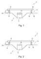
- the figures show a total provided with the reference numeral 2 covering device for a tank unit 4 of a motor vehicle.
- the covering device 2 comprises a planar cover element 6, which in FIG. 1 is shown in its closed functional position. In the closed functional position, the cover element 6 overflows a tank opening 8 as well as a closure means 10 closing the tank opening 8 FIG. 1
- Covering device 2 shown a sealant 12 disposed on the cover 6. This closes an existing between the cover 6 and the tank opening 8 gap 14 which extends transversely to the tank opening 8 and the tank opening 8 is spaced.
- the sealing means 12 is designed in such a way that it completely surrounds the tank opening 8 in the closed functional position.
- the sealing means 12 is formed from a flat material which is extended with a broad side 14 transversely to the plane of the planar cover member 6.
- the sealant 12 with its broad side 15 at a surrounding the tank opening 8 edge element 16 from the outside.
- the sealing means 12 is spaced from the tank unit 4 with a free end 18 remote from the cover element 6.
- the cover 2 In order to transfer the cover element 6 from the closed functional position into an open functional position in which the tank opening 8 and / or the closure means 10 of FIG outside accessible, the cover 2 includes a guide means 20, by the cover 6 is rotatable in the open functional position.
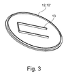
- FIG. 2 shows a second embodiment in which the sealing means 12 with its broad side 15 abuts on a tank opening 8 surrounding edge element 16 from the inside.
- FIG. 3 shows a plan view of the cover 2 according to FIG. 1 , It can be seen here that the at least one sealing means 12 comprises an outer sealing means 12 'which bears against the edge element 16 of the tank unit 4.
- cover member 6 comprises a support means 13 which rests against the tank opening 8 or the closure means 10.
Landscapes
- Engineering & Computer Science (AREA)
- Life Sciences & Earth Sciences (AREA)
- Sustainable Development (AREA)
- Sustainable Energy (AREA)
- Chemical & Material Sciences (AREA)
- Combustion & Propulsion (AREA)
- Transportation (AREA)
- Mechanical Engineering (AREA)
- Cooling, Air Intake And Gas Exhaust, And Fuel Tank Arrangements In Propulsion Units (AREA)
Abstract
Description
- Die Erfindung betrifft eine Abdeckeinrichtung für eine Tankeinheit eines Kraftfahrzeugs, mit mindestens einem flächenhaften Abdeckelement, das von einer geschlossenen Funktionsstellung, in der das Abdeckelement eine Tanköffnung der Tankeinheit und/oder ein die Tanköffnung verschließendes Verschlussmittel der Tankeinheit überfängt, in eine geöffnete Funktionsstellung, in der die Tanköffnung und/oder das Verschlussmittel von außen zugänglich ist, überführbar ist, und mit mindestens einem Dichtmittel durch das ein in der geschlossenen Funktionsstellung zwischen Abdeckelement und Tankeinheit bestehender und quer oder schräg zur Tanköffnung erstreckter Spalt verschließbar oder verschlossen ist. Darüber hinaus betrifft die Erfindung eine Tankeinheit mit einer derartigen Abdeckeinrichtung sowie ein Kraftfahrzeug mit einer derartigen Tankeinheit und/oder mit einer derartigen Abdeckeinrichtung.
- Eine nicht gattungsgemäße Abdeckeinrichtung ist bekannt aus
DE 11 2008 003 238 T5 , bei der axial an einer Tanköffnung ein Dichtmittel angeordnet ist, das am Abdeckelement in einer geschlossenen Funktionsstellung anliegt. Hierbei hat es sich als nachteilig herausgestellt, dass Staub oder Schmutz durch einen Spalt zwischen Abdeckelement und Tankeinheit unterhalb des Abdeckelements gelangen kann. - Aufgabe der Erfindung ist, eine Abdeckeinrichtung vorzuschlagen, bei der ein Eindringen von Staub oder Schmutz zwischen Abdeckelement und Tankeinheit zumindest reduziert ist.
- Diese Erfindung wird durch eine eingangs genannte Abdeckeinrichtung erfindungsgemäß dadurch gelöst, dass das Dichtmittel am Abdeckelement und derart angeordnet ist, dass ein zur Tanköffnung beabstandeter Spalt verschließbar oder verschlossen ist.
- Dadurch, dass am Abdeckelement ein Dichtelement vorgesehen ist, das einen zwischen Abdeckelement und Tanköffnung bestehenden und quer oder schräg zur Tanköffnung erstreckten und zur Tanköffnung beabstandeten Spalt verschließt, ist einem Eindringen von Staub oder Schmutz vorgebeugt. Dadurch, dass das Dichtelement am Abdeckelement angeordnet ist, bilden Abdeckelement und Dichtmittel eine vormontierbare Einheit, bei der das Dichtmittel auf einfache Weise am Abdeckelement festlegbar oder festgelegt ist.
- Darüber hinaus ist es denkbar, dass das Dichtmittel die Tanköffnung in der geschlossenen Funktionsstellung in Gänze oder zumindest abschnittsweise umgibt.
- Wenn das Dichtmittel die Tanköffnung in Gänze umgibt, stellt das Dichtmittel einen guten Schutz gegen das Eindringen von Schmutz oder Staub dar. Wenn das Dichtmittel die Tanköffnung abschnittsweise umgibt, kann das Dichtmittel beispielsweise an weiteren Komponenten der Abdeckeinrichtung oder der Tankeinheit anliegen, so dass diese Komponenten funktional zur Dichtwirkung des Dichtmittels beitragen.
- Ferner ist es denkbar, dass das mindestens eine Dichtmittel in der geschlossenen Funktionsstellung mit seinem freien, dem Abdeckelement abgewandten Ende an der Tankeinheit anliegt oder zur Tankeinheit beabstandet ist.
- Das Dichtmittel kann grundsätzlich beliebig gebildet sein. Beispielsweise kann es schwammartig ausgebildet sein. Es erweist sich als vorteilhaft, wenn das Dichtmittel ein Flachmaterial umfasst, das mit einer Breitseite quer oder schräg von der Ebene des Flächenhaften Abdeckelements wegerstreckt ist. Solchenfalls ist das Dichtmittel lippenartig ausgebildet.
- Das Dichtmittel kann starr oder elastisch verformbar sein.
- In Weiterbildung letztgenannten Erfindungsgedankens erweist es sich als vorteilhaft, wenn das Dichtmittel mit seiner Breitseite zumindest abschnittsweise an einem die Tanköffnung umgebenden Randelement der Tankeinheit von innen oder von außen anliegt. Hierdurch überlappt das Dichtmittel - quer oder schräg zur Tanköffnung betrachtet - das Randelement.
- Das Randelement kann einen Kunststoff umfassen. Er kann elastisch verformbar ausgebildet sein, wodurch die Dichtwirkung in der geschlossenen Funktionsstellung erhöht ist.
- Bei einer Ausführungsform der erfindungsgemäßen Abdeckeinrichtung erweist es sich als vorteilhaft, wenn das mindestens eine Dichtmittel ein äußeres Dichtmittel, das in der geschlossenen Funktionsstellung am Randelement anliegt, und mindestens ein inneres Dichtmittel, das in der geschlossenen Funktionsstellung unmittelbar an der Tanköffnung und/oder an dem Verschlussmittel anliegt, umfasst.
- Dadurch ist die Dichtwirkung der Abdeckeinrichtung weiter erhöht und die Gefahr eines Eindringen von Schmutz oder Staub weiter reduziert.
- Das Dichtmittel kann grundsätzlich ein beliebiges Material umfassen, beispielsweise ein Gewebe oder dergleichen. Es erweist sich jedoch als kostengünstig, wenn das Dichtmittel einen Kunststoff oder ein Gummi, umfasst. Darüber hinaus kann das Dichtmittel aus dem gleichen Material wie das Abdeckelement gebildet sein. Solchenfalls können Abdeckelement und Dichtmittel als Spritzgussteil einfach hergestellt werden.
- Darüber hinaus ist es denkbar, dass das Dichtmittel an einer beliebigen Stelle des Abdeckelements angeordnet ist. Um die Gefahr eines Eindringens von Staub oder Schmutz in den zwischen Abdeckelement und Tankeinheit gebildeten Hohlraum zu reduzieren, erweist es sich als vorteilhaft, wenn das Dichtmittel am Rand des flächenhaften Abdeckelements angeordnet ist.
- Ferner kann das Abdeckelement ein rippenartiges Stützmittel umfassen, das in der geschlossenen Funktionsstellung an der Tanköffnung und/oder am Randelement abgestützt ist. Hierdurch sind Vibrationen beim Betrieb des Kraftfahrzeugs reduziert.
- Grundsätzlich ist es denkbar, dass das Abdeckelement auf beliebige Weise von der geöffneten Funktionsstellung in die geschlossene Funktionsstellung und wieder zurück überführt werden kann. Es erweist sich als einfach und kostengünstig, wenn die Abdeckeinrichtung mindestens ein Führungsmittel umfasst, das einerseits am Abdeckelement und andererseits an der Tankeinheit oder einem Karosserieelement festlegbar oder festgelegt ist, und das das Überführen des Abdeckelements von der geschlossenen Funktionsstellung in die geöffnete Funktionsstellung führt.
- Das Führungsmittel lässt sich einfach ausführen, wenn das Führungsmittel ein Scharnier und/oder Gelenk umfasst, mit dem das Abdeckelement von der geschlossenen Funktionsstellung in die geöffnete Funktionsstellung klappbar, insbesondere drehbar ist.
- Ferner wird die Aufgabe gelöst durch eine Tankeinheit eines Kraftfahrzeugs mit mindestens einer Tanköffnung, insbesondere mit einem der zuvor genannten Merkmale, mit mindestens einem die Tanköffnung verschließenden Verschlussmittel und mit mindestens einer Abdeckeinrichtung die mindestens ein flächenhaftes Abdeckelement umfasst, das von einer geschlossenen Funktionsstellung, in der das Abdeckelement die Tanköffnung und/oder das die Tanköffnung verschließende Verschlussmittel überfängt, in eine geöffnete Funktionsstellung, in der die Tanköffnung und/oder das Verschlussmittel von außen zugänglich ist, überführbar ist und die mindestens ein Dichtmittel umfasst, durch das ein in der geschlossenen Funktionsstellung zwischen Abdeckelement und Tanköffnung bestehender und quer oder schräg zur Tanköffnung erstreckter Spalt verschließbar oder verschlossen ist, wobei das Dichtmittel am Abdeckelement angeordnet ist.
- Schließlich wird die Aufgabe gelöst durch ein Kraftfahrzeug mit mindestens einer Tankeinheit, insbesondere mit einem der zuvor genannten Merkmale, und/oder mit mindestens einer Abdeckeinrichtung, insbesondere mit einem der zuvor genannten Merkmale.
- Die erfindungsgemäße Abdeckeinrichtung, die erfindungsgemäße Tankeinheit sowie das erfindungsgemäße Kraftfahrzeug erweisen sich in mehrfacher Hinsicht als vorteilhaft:
- Dadurch, dass am Abdeckelement ein Dichtmittel vorgesehen ist, das einen zwischen Abdeckelement und Tanköffnung bestehenden und quer oder schräg zur Tanköffnung erstreckten und beabstandeten Spalt verschließt, ist die Gefahr eines Eindringens von Schmutz oder Staub zumindest reduziert.
- Die Gefahr eines Eindringens von Staub und Verschmutzung ist weiter reduziert, wenn das mindestens eine Dichtmittel ein äußeres Dichtmittel und ein inneres Dichtmittel umfasst.
- Vibrationen sind reduziert, wenn sich die Abdeckeinrichtung mit meinem Stützmittel an der Tanköffnung oder Verschlussmittel abstützt.
- Weitere Merkmale, Einzelheiten sowie Vorteile der Erfindung entnehmen sich aus den beigefügten Patentansprüchen, aus den zeichnerischen Darstellungen und nachfolgender Beschreibung einer bevorzugte Ausführungsform einer erfindungsgemäßen Abdeckeinrichtung sowie einer erfindungsgemäßen Tankeinheit für ein Kraftfahrzeug.
- In der Zeichnung zeigt:
- Figur 1
- eine geschnittene Seitenansicht durch eine erste Ausführungsform der erfindungsgemäße Abdeckeinrichtung;
- Figur 2
- eine geschnittene Seitenansicht durch eine zweite Ausführungsform der erfindungsgemäße Abdeckeinrichtung;
- Figur 3
- eine Unteransicht auf die erfindungsgemäße Abdeckeinrichtung gemäß
Figur 1 . - Die Figuren zeigen eine insgesamt mit dem Bezugszeichen 2 versehene Abdeckeinrichtung für eine Tankeinheit 4 eines Kraftfahrzeugs. Die Abdeckeinrichtung 2 umfasst ein flächenhaftes Abdeckelement 6, das in
Figur 1 in seiner geschlossenen Funktionsstellung gezeigt ist. In der geschlossenen Funktionsstellung überfängt das Abdeckelement 6 eine Tanköffnung 8 sowie ein die Tanköffnung 8 verschließendes Verschlussmittel 10. Darüber hinaus ist bei der inFigur 1 dargestellten Abdeckeinrichtung 2 ein Dichtmittel 12 am Abdeckelement 6 angeordnet. Dieses verschließt einen zwischen dem Abdeckelement 6 und der Tanköffnung 8 bestehenden Spalt 14, der quer zur Tanköffnung 8 erstreckt und zur Tanköffnung 8 beabstandet ist. - Bei dem in
Figur 1 gezeigten Ausführungsbeispiel ist das Dichtmittel 12 derart ausgebildet, dass es die Tanköffnung 8 in der geschlossenen Funktionsstellung in Gänze umgibt. Hierzu ist das Dichtmittel 12 aus einem Flachmaterial gebildet, das mit einer Breitseite 14 quer zur Ebene des flächenhaften Abdeckelements 6 erstreckt ist. - Bei dem Ausführungsbeispiel gemäß
Figur 1 liegt das Dichtmittel 12 mit seiner Breitseite 15 an einem die Tanköffnung 8 umgebenden Randelement 16 von außen an. Hierbei ist das Dichtmittel 12 mit einem freien, dem Abdeckelement 6 abgewandten Ende 18 zur Tankeinheit 4 beabstandet. - Um das Abdeckelement 6 von der geschlossenen Funktionsstellung in eine geöffnete Funktionsstellung zu überführen, in der die Tanköffnung 8 und/oder das Verschlussmittel 10 von außen zugänglich ist, umfasst die Abdeckeinrichtung 2 ein Führungsmittel 20, durch dass das Abdeckelement 6 in die geöffnete Funktionsstellung drehbar ist.
-
Figur 2 zeigt ein zweites Ausführungsbeispiel bei dem Dichtmittel 12 mit seiner Breitseite 15 an einem die Tanköffnung 8 umgebenden Randelement 16 von innen anliegt. -
Figur 3 zeigt eine Draufsicht auf die Abdeckeinrichtung 2 gemäßFigur 1 . Hierbei ist ersichtlich, dass das mindestens eine Dichtmittel 12 ein äußeres Dichtmittel 12' umfasst, das an dem Randelement 16 der Tankeinheit 4 anliegt. - Ferner umfasst das Abdeckelement 6 ein Stützmittel 13, das an der Tanköffnung 8 oder dem Verschlussmittel 10 anliegt.
- Die in der vorstehenden Beschreibung, in den Ansprüchen, sowie in den Zeichnungen gezeigten Merkmale der Erfindung können sowohl einzeln, als auch in jeder beliebigen Kombination in der Verwirklichung der Erfindung und ihren verschiedenen Ausführungsformen wesentlich sein.
-
- 2
- Abdeckeinrichtung
- 4
- Tankeinheit
- 6
- Abdeckelement
- 8
- Tanköffnung
- 10
- Verschlussmittel
- 12
- Dichtmittel
- 12'
- äußeres Dichtmittel
- 13
- Stützmittel
- 14
- Spalt
- 15
- Breitseite
- 16
- Randelement
- 18
- freies Ende
- 20
- Führungsmittel
Claims (13)
- Abdeckeinrichtung (2) für eine Tankeinheit (4) eines Kraftfahrzeugs, mit mindestens einem flächenhaften Abdeckelement (6), das von einer geschlossenen Funktionsstellung, in der das Abdeckelement (6) eine Tanköffnung (8) der Tankeinheit (4) und/oder ein die Tanköffnung (8) verschließendes Verschlussmittel (10) der Tankeinheit (4) überfängt, in eine geöffnete Funktionsstellung, in der die Tanköffnung (8) und/oder das Verschlussmittel (10) von außen zugänglich ist, überführbar ist, und mit mindestens einem Dichtmittel (12) durch das ein in der geschlossenen Funktionsstellung zwischen Abdeckelement (6) und Tankeinheit (4) bestehender und quer oder schräg zur Tanköffnung (8) erstreckter und zur Tanköffnung (8) beabstandeter Spalt (14) verschließbar oder verschlossen ist, dadurch gekennzeichnet, dass das Dichtmittel (12) am Abdeckelement (6) und derart angeordnet ist, dass ein zur Tanköffnung (8) beabstandeter Spalt (14) verschließbar oder verschlossen ist.
- Abdeckeinrichtung (2) nach Anspruch 1, dadurch gekennzeichnet, dass das Dichtmittel (12) die Tanköffnung (8) in der geschlossenen Funktionsstellung in Gänze oder zumindest abschnittsweise umgibt.
- Abdeckeinrichtung (2) nach Anspruch 1 oder 2, dadurch gekennzeichnet, dass das mindestens eine Dichtmittel (12) in der geschlossenen Funktionsstellung mit seinem freien, dem Abdeckelement (6) abgewandten Ende an der Tankeinheit (4) anliegt oder zur Tankeinheit (4) beabstandet ist.
- Abdeckeinrichtung (2) nach mindestens einem der vorhergehenden Ansprüche,
dadurch gekennzeichnet, dass
das Dichtmittel (12) ein Flachmaterial umfasst, das mit einer Breitseite (15) quer oder schräg von der Ebene des flächenhaften Abdeckelements (6) wegerstreckt ist. - Abdeckeinrichtung (2) nach Anspruch 4, dadurch gekennzeichnet, dass das Dichtmittel (12) mit seiner Breitseite (15) zumindest abschnittsweise an einem die Tanköffnung (8) umgebenen Randelement (16) der Tankeinheit (4) von innen oder von außen anliegt.
- Abdeckeinrichtung (2) nach mindestens einem der vorhergehenden Ansprüche,
dadurch gekennzeichnet, dass
das mindestens eine Dichtmittel (12) ein äußeres Dichtmittel (12'), das in der geschlossenen Funktionsstellung am Randelement (16) anliegt, und mindestens ein inneres Dichtmittel (12''), das in der geschlossenen Funktionsstellung unmittelbar an der Tanköffnung (8) und/oder an dem Verschlussmittel (10) anliegt, umfasst. - Abdeckeinrichtung (2) nach mindestens einem der vorhergehenden Ansprüche,
dadurch gekennzeichnet, dass
das Dichtmittel (12) einen Kunststoff oder ein Gummi umfasst. - Abdeckeinrichtung (2) nach mindestens einem der vorhergehenden Ansprüche,
dadurch gekennzeichnet, dass
das Dichtmittel (12) am Rand des flächenhaften Abdeckelements (6) angeordnet ist. - Abdeckeinrichtung (2) nach mindestens einem der vorhergehenden Ansprüche, dadurch gekennzeichnet, dass das Abdeckelement (6) ein rippenartiges Stützmittel (13) umfasst, das in der geschlossenen Funktionsstellung an der Tanköffnung (8) und/oder am Randelement (16) abstützt ist.
- Abdeckeinrichtung (2) nach mindestens einem der vorhergehenden Ansprüche,
gekennzeichnet durch
mindestens ein Führungsmittel (20), das einerseits am Abdeckelement (6) und andererseits an der Tankeinheit (4) oder einem Karosserieelement festlegbar oder festgelegt ist, und das das Überführen des Abdeckelements (6) von der geschlossenen Funktionsstellung in die geöffnete Funktionsstellung führt. - Abdeckeinrichtung (2) nach Anspruch 10, dadurch gekennzeichnet, dass das Führungsmittel (20) ein Scharnier und/oder Gelenk umfasst, mit dem das Abdeckelement (6) von der geschlossenen Funktionsstellung in die geöffnete Funktionsstellung klappbar, insbesondere drehbar ist.
- Tankeinheit (4) eines Kraftfahrzeugs mit mindestens einer Tanköffnung (8), mit mindestens einem die Tanköffnung (8) verschließenden Verschlussmittel (10) und mit mindestens einer Abdeckeinrichtung (2), insbesondere nach einem der Ansprüche 1 bis 11, die mindestens ein flächenhaftes Abdeckelement (6) umfasst, das von einer geschlossenen Funktionsstellung, in der das Abdeckelement (6) die Tanköffnung (8) und/oder das die Tanköffnung (8) verschließende Verschlussmittel (10) überfängt, in eine geöffnete Funktionsstellung, in der die Tanköffnung (8) und/oder das Verschlussmittel (10) von außen zugänglich ist, überführbar ist und die mindestens ein Dichtmittel (12) umfasst, durch das ein in der geschlossenen Funktionsstellung zwischen Abdeckelement (6) und Tanköffnung (8) bestehender und quer oder schräg zur Tanköffnung (8) erstreckter Spalt (14) verschließbar oder verschlossen ist, dadurch gekennzeichnet, dass das Dichtmittel (12) am Abdeckelement (6) angeordnet ist.
- Kraftfahrzeug mit mindestens einer Tankeinheit (4), insbesondere nach Anspruch 12, und/oder mit mindestens einer Abdeckeinrichtung (2), insbesondere nach einem der Ansprüche 1 bis 11.
Priority Applications (1)
| Application Number | Priority Date | Filing Date | Title |
|---|---|---|---|
| EP12197878.7A EP2746088B1 (de) | 2012-12-18 | 2012-12-18 | Abdeckeinrichtung |
Applications Claiming Priority (1)
| Application Number | Priority Date | Filing Date | Title |
|---|---|---|---|
| EP12197878.7A EP2746088B1 (de) | 2012-12-18 | 2012-12-18 | Abdeckeinrichtung |
Publications (2)
| Publication Number | Publication Date |
|---|---|
| EP2746088A1 true EP2746088A1 (de) | 2014-06-25 |
| EP2746088B1 EP2746088B1 (de) | 2015-04-15 |
Family
ID=47681517
Family Applications (1)
| Application Number | Title | Priority Date | Filing Date |
|---|---|---|---|
| EP12197878.7A Active EP2746088B1 (de) | 2012-12-18 | 2012-12-18 | Abdeckeinrichtung |
Country Status (1)
| Country | Link |
|---|---|
| EP (1) | EP2746088B1 (de) |
Citations (4)
| Publication number | Priority date | Publication date | Assignee | Title |
|---|---|---|---|---|
| US5954387A (en) * | 1998-02-26 | 1999-09-21 | Christopher M. Fisher | Fuel access door with affixed seal |
| FR2836427A1 (fr) * | 2002-02-22 | 2003-08-29 | Neyr Plastiques Holding | Portillon pour trappe de remplissage |
| US20090189410A1 (en) * | 2008-01-25 | 2009-07-30 | Gurtatowski Craig W | Hinge mounted fuel housing seal |
| DE112008003238T5 (de) | 2007-11-29 | 2010-09-16 | Toyota Jidosha Kabushiki Kaisha, Toyota-shi | Anordnung für den Betankungsabschnitt eines Kraftstofftanks |
-
2012
- 2012-12-18 EP EP12197878.7A patent/EP2746088B1/de active Active
Patent Citations (4)
| Publication number | Priority date | Publication date | Assignee | Title |
|---|---|---|---|---|
| US5954387A (en) * | 1998-02-26 | 1999-09-21 | Christopher M. Fisher | Fuel access door with affixed seal |
| FR2836427A1 (fr) * | 2002-02-22 | 2003-08-29 | Neyr Plastiques Holding | Portillon pour trappe de remplissage |
| DE112008003238T5 (de) | 2007-11-29 | 2010-09-16 | Toyota Jidosha Kabushiki Kaisha, Toyota-shi | Anordnung für den Betankungsabschnitt eines Kraftstofftanks |
| US20090189410A1 (en) * | 2008-01-25 | 2009-07-30 | Gurtatowski Craig W | Hinge mounted fuel housing seal |
Also Published As
| Publication number | Publication date |
|---|---|
| EP2746088B1 (de) | 2015-04-15 |
Similar Documents
| Publication | Publication Date | Title |
|---|---|---|
| DE102012018826A1 (de) | Spindelantrieb für ein Verstellelement eines Kraftfahrzeugs | |
| DE102004015136B3 (de) | Betätigungseinrichtung für ein Kraftfahrzeug-Türschloss | |
| DE202007002306U1 (de) | Antriebseinheit zur Betätigung einer Kraftfahrzeug-Klappe | |
| DE102015014819A1 (de) | Halteanordnung einer Bordkantendichtung an einer Seitentür eines Kraftwagens, insbesondere eines Pesonenkraftwagens | |
| DE102008043304A1 (de) | Getriebe sowie Getriebe-Antriebseinheit | |
| DE102017101607A1 (de) | Spoileranordnung eines Kraftfahrzeugs | |
| DE102018129748A1 (de) | Motorgehäuse eines Antriebsmotors für einen Kraftfahrzeug-Stellantrieb | |
| DE102018110399A1 (de) | Entlüftungsanordnung für ein fahrzeug mit geräuschdämpfungsklappe | |
| DE102013109837A1 (de) | Kabelmarker | |
| DE102015000465A1 (de) | Schaltervorrichtung und kraftfahrzeug | |
| DE202012104622U1 (de) | Windabweiseranordung für ein Kraftfahrzeugdach | |
| DE102017126766A1 (de) | Fahrzeugkomponente | |
| DE102014004738A1 (de) | Filter mit Hybridrahmen | |
| EP2746088B1 (de) | Abdeckeinrichtung | |
| DE102015108733A1 (de) | Kraftfahrzeugschloss | |
| DE102014203175A1 (de) | Kraftfahrzeug | |
| DE102016012821A1 (de) | Tankmuldeneinheit mit spielfreier Schnittstelle zwischen Tankdeckel und Zentralverriegelungs-Steller | |
| DE102023003511A1 (de) | Abdeckanordnung, Verkleidungsanordnung, Heckklappensystem und Kraftfahrzeug | |
| DE102014106372A1 (de) | Verschlusseinheit für einen Luftführungskanal eines Kraftfahrzeugs | |
| DE102009027325A1 (de) | Verriegelungsvorrichtung | |
| EP1241082B1 (de) | Kraftfahrzeug mit wenigstens einer klappbaren Haube, insbesondere Motorraum- und/oder Gepäckraumdeckel | |
| DE102014204179B4 (de) | Vorrichtung zur Begrenzung des Öffnungswinkels eines Flügels einer Tür oder eines Fensters | |
| DE102011104374A1 (de) | Glasdeckel für ein Kraftfahrzeug-Dach | |
| DE102017122272A1 (de) | Tankdeckelaufbau | |
| DE102015100664A1 (de) | Verstellanordnung für einen Heckdeckel eines Kraftfahrzeuges |
Legal Events
| Date | Code | Title | Description |
|---|---|---|---|
| PUAI | Public reference made under article 153(3) epc to a published international application that has entered the european phase |
Free format text: ORIGINAL CODE: 0009012 |
|
| 17P | Request for examination filed |
Effective date: 20140115 |
|
| AK | Designated contracting states |
Kind code of ref document: A1 Designated state(s): AL AT BE BG CH CY CZ DE DK EE ES FI FR GB GR HR HU IE IS IT LI LT LU LV MC MK MT NL NO PL PT RO RS SE SI SK SM TR |
|
| AX | Request for extension of the european patent |
Extension state: BA ME |
|
| RIC1 | Information provided on ipc code assigned before grant |
Ipc: B60K 15/04 20060101AFI20140725BHEP Ipc: B60K 15/05 20060101ALN20140725BHEP Ipc: B60K 15/035 20060101ALN20140725BHEP |
|
| GRAP | Despatch of communication of intention to grant a patent |
Free format text: ORIGINAL CODE: EPIDOSNIGR1 |
|
| RIC1 | Information provided on ipc code assigned before grant |
Ipc: B60K 15/035 20060101ALN20140902BHEP Ipc: B60K 15/05 20060101ALN20140902BHEP Ipc: B60K 15/04 20060101AFI20140902BHEP |
|
| INTG | Intention to grant announced |
Effective date: 20140916 |
|
| GRAS | Grant fee paid |
Free format text: ORIGINAL CODE: EPIDOSNIGR3 |
|
| GRAA | (expected) grant |
Free format text: ORIGINAL CODE: 0009210 |
|
| AK | Designated contracting states |
Kind code of ref document: B1 Designated state(s): AL AT BE BG CH CY CZ DE DK EE ES FI FR GB GR HR HU IE IS IT LI LT LU LV MC MK MT NL NO PL PT RO RS SE SI SK SM TR |
|
| REG | Reference to a national code |
Ref country code: GB Ref legal event code: FG4D Free format text: NOT ENGLISH Ref country code: CH Ref legal event code: EP |
|
| REG | Reference to a national code |
Ref country code: IE Ref legal event code: FG4D Free format text: LANGUAGE OF EP DOCUMENT: GERMAN |
|
| REG | Reference to a national code |
Ref country code: AT Ref legal event code: REF Ref document number: 721737 Country of ref document: AT Kind code of ref document: T Effective date: 20150515 |
|
| REG | Reference to a national code |
Ref country code: DE Ref legal event code: R096 Ref document number: 502012002851 Country of ref document: DE Effective date: 20150528 |
|
| REG | Reference to a national code |
Ref country code: NL Ref legal event code: VDEP Effective date: 20150415 |
|
| REG | Reference to a national code |
Ref country code: LT Ref legal event code: MG4D |
|
| PG25 | Lapsed in a contracting state [announced via postgrant information from national office to epo] |
Ref country code: NL Free format text: LAPSE BECAUSE OF FAILURE TO SUBMIT A TRANSLATION OF THE DESCRIPTION OR TO PAY THE FEE WITHIN THE PRESCRIBED TIME-LIMIT Effective date: 20150415 |
|
| PG25 | Lapsed in a contracting state [announced via postgrant information from national office to epo] |
Ref country code: LT Free format text: LAPSE BECAUSE OF FAILURE TO SUBMIT A TRANSLATION OF THE DESCRIPTION OR TO PAY THE FEE WITHIN THE PRESCRIBED TIME-LIMIT Effective date: 20150415 Ref country code: FI Free format text: LAPSE BECAUSE OF FAILURE TO SUBMIT A TRANSLATION OF THE DESCRIPTION OR TO PAY THE FEE WITHIN THE PRESCRIBED TIME-LIMIT Effective date: 20150415 Ref country code: NO Free format text: LAPSE BECAUSE OF FAILURE TO SUBMIT A TRANSLATION OF THE DESCRIPTION OR TO PAY THE FEE WITHIN THE PRESCRIBED TIME-LIMIT Effective date: 20150715 Ref country code: ES Free format text: LAPSE BECAUSE OF FAILURE TO SUBMIT A TRANSLATION OF THE DESCRIPTION OR TO PAY THE FEE WITHIN THE PRESCRIBED TIME-LIMIT Effective date: 20150415 Ref country code: HR Free format text: LAPSE BECAUSE OF FAILURE TO SUBMIT A TRANSLATION OF THE DESCRIPTION OR TO PAY THE FEE WITHIN THE PRESCRIBED TIME-LIMIT Effective date: 20150415 Ref country code: PT Free format text: LAPSE BECAUSE OF FAILURE TO SUBMIT A TRANSLATION OF THE DESCRIPTION OR TO PAY THE FEE WITHIN THE PRESCRIBED TIME-LIMIT Effective date: 20150817 |
|
| PG25 | Lapsed in a contracting state [announced via postgrant information from national office to epo] |
Ref country code: IS Free format text: LAPSE BECAUSE OF FAILURE TO SUBMIT A TRANSLATION OF THE DESCRIPTION OR TO PAY THE FEE WITHIN THE PRESCRIBED TIME-LIMIT Effective date: 20150815 Ref country code: LV Free format text: LAPSE BECAUSE OF FAILURE TO SUBMIT A TRANSLATION OF THE DESCRIPTION OR TO PAY THE FEE WITHIN THE PRESCRIBED TIME-LIMIT Effective date: 20150415 Ref country code: RS Free format text: LAPSE BECAUSE OF FAILURE TO SUBMIT A TRANSLATION OF THE DESCRIPTION OR TO PAY THE FEE WITHIN THE PRESCRIBED TIME-LIMIT Effective date: 20150415 Ref country code: GR Free format text: LAPSE BECAUSE OF FAILURE TO SUBMIT A TRANSLATION OF THE DESCRIPTION OR TO PAY THE FEE WITHIN THE PRESCRIBED TIME-LIMIT Effective date: 20150716 |
|
| REG | Reference to a national code |
Ref country code: FR Ref legal event code: PLFP Year of fee payment: 4 |
|
| REG | Reference to a national code |
Ref country code: DE Ref legal event code: R097 Ref document number: 502012002851 Country of ref document: DE |
|
| PG25 | Lapsed in a contracting state [announced via postgrant information from national office to epo] |
Ref country code: DK Free format text: LAPSE BECAUSE OF FAILURE TO SUBMIT A TRANSLATION OF THE DESCRIPTION OR TO PAY THE FEE WITHIN THE PRESCRIBED TIME-LIMIT Effective date: 20150415 Ref country code: EE Free format text: LAPSE BECAUSE OF FAILURE TO SUBMIT A TRANSLATION OF THE DESCRIPTION OR TO PAY THE FEE WITHIN THE PRESCRIBED TIME-LIMIT Effective date: 20150415 |
|
| PLBE | No opposition filed within time limit |
Free format text: ORIGINAL CODE: 0009261 |
|
| STAA | Information on the status of an ep patent application or granted ep patent |
Free format text: STATUS: NO OPPOSITION FILED WITHIN TIME LIMIT |
|
| PG25 | Lapsed in a contracting state [announced via postgrant information from national office to epo] |
Ref country code: CZ Free format text: LAPSE BECAUSE OF FAILURE TO SUBMIT A TRANSLATION OF THE DESCRIPTION OR TO PAY THE FEE WITHIN THE PRESCRIBED TIME-LIMIT Effective date: 20150415 Ref country code: RO Free format text: LAPSE BECAUSE OF NON-PAYMENT OF DUE FEES Effective date: 20150415 Ref country code: PL Free format text: LAPSE BECAUSE OF FAILURE TO SUBMIT A TRANSLATION OF THE DESCRIPTION OR TO PAY THE FEE WITHIN THE PRESCRIBED TIME-LIMIT Effective date: 20150415 Ref country code: SK Free format text: LAPSE BECAUSE OF FAILURE TO SUBMIT A TRANSLATION OF THE DESCRIPTION OR TO PAY THE FEE WITHIN THE PRESCRIBED TIME-LIMIT Effective date: 20150415 |
|
| 26N | No opposition filed |
Effective date: 20160118 |
|
| PG25 | Lapsed in a contracting state [announced via postgrant information from national office to epo] |
Ref country code: IT Free format text: LAPSE BECAUSE OF FAILURE TO SUBMIT A TRANSLATION OF THE DESCRIPTION OR TO PAY THE FEE WITHIN THE PRESCRIBED TIME-LIMIT Effective date: 20150415 |
|
| PG25 | Lapsed in a contracting state [announced via postgrant information from national office to epo] |
Ref country code: SI Free format text: LAPSE BECAUSE OF FAILURE TO SUBMIT A TRANSLATION OF THE DESCRIPTION OR TO PAY THE FEE WITHIN THE PRESCRIBED TIME-LIMIT Effective date: 20150415 Ref country code: BE Free format text: LAPSE BECAUSE OF NON-PAYMENT OF DUE FEES Effective date: 20151231 |
|
| PG25 | Lapsed in a contracting state [announced via postgrant information from national office to epo] |
Ref country code: MC Free format text: LAPSE BECAUSE OF FAILURE TO SUBMIT A TRANSLATION OF THE DESCRIPTION OR TO PAY THE FEE WITHIN THE PRESCRIBED TIME-LIMIT Effective date: 20150415 Ref country code: LU Free format text: LAPSE BECAUSE OF FAILURE TO SUBMIT A TRANSLATION OF THE DESCRIPTION OR TO PAY THE FEE WITHIN THE PRESCRIBED TIME-LIMIT Effective date: 20151218 |
|
| REG | Reference to a national code |
Ref country code: CH Ref legal event code: PL |
|
| REG | Reference to a national code |
Ref country code: IE Ref legal event code: MM4A |
|
| PG25 | Lapsed in a contracting state [announced via postgrant information from national office to epo] |
Ref country code: CH Free format text: LAPSE BECAUSE OF NON-PAYMENT OF DUE FEES Effective date: 20151231 Ref country code: LI Free format text: LAPSE BECAUSE OF NON-PAYMENT OF DUE FEES Effective date: 20151231 Ref country code: IE Free format text: LAPSE BECAUSE OF NON-PAYMENT OF DUE FEES Effective date: 20151218 |
|
| REG | Reference to a national code |
Ref country code: FR Ref legal event code: PLFP Year of fee payment: 5 |
|
| PG25 | Lapsed in a contracting state [announced via postgrant information from national office to epo] |
Ref country code: SM Free format text: LAPSE BECAUSE OF FAILURE TO SUBMIT A TRANSLATION OF THE DESCRIPTION OR TO PAY THE FEE WITHIN THE PRESCRIBED TIME-LIMIT Effective date: 20150415 Ref country code: HU Free format text: LAPSE BECAUSE OF FAILURE TO SUBMIT A TRANSLATION OF THE DESCRIPTION OR TO PAY THE FEE WITHIN THE PRESCRIBED TIME-LIMIT; INVALID AB INITIO Effective date: 20121218 Ref country code: BG Free format text: LAPSE BECAUSE OF FAILURE TO SUBMIT A TRANSLATION OF THE DESCRIPTION OR TO PAY THE FEE WITHIN THE PRESCRIBED TIME-LIMIT Effective date: 20150415 |
|
| PG25 | Lapsed in a contracting state [announced via postgrant information from national office to epo] |
Ref country code: CY Free format text: LAPSE BECAUSE OF FAILURE TO SUBMIT A TRANSLATION OF THE DESCRIPTION OR TO PAY THE FEE WITHIN THE PRESCRIBED TIME-LIMIT Effective date: 20150415 Ref country code: SE Free format text: LAPSE BECAUSE OF FAILURE TO SUBMIT A TRANSLATION OF THE DESCRIPTION OR TO PAY THE FEE WITHIN THE PRESCRIBED TIME-LIMIT Effective date: 20150415 |
|
| PG25 | Lapsed in a contracting state [announced via postgrant information from national office to epo] |
Ref country code: MT Free format text: LAPSE BECAUSE OF FAILURE TO SUBMIT A TRANSLATION OF THE DESCRIPTION OR TO PAY THE FEE WITHIN THE PRESCRIBED TIME-LIMIT Effective date: 20150415 |
|
| REG | Reference to a national code |
Ref country code: FR Ref legal event code: PLFP Year of fee payment: 6 |
|
| PG25 | Lapsed in a contracting state [announced via postgrant information from national office to epo] |
Ref country code: MK Free format text: LAPSE BECAUSE OF FAILURE TO SUBMIT A TRANSLATION OF THE DESCRIPTION OR TO PAY THE FEE WITHIN THE PRESCRIBED TIME-LIMIT Effective date: 20150415 |
|
| PG25 | Lapsed in a contracting state [announced via postgrant information from national office to epo] |
Ref country code: TR Free format text: LAPSE BECAUSE OF FAILURE TO SUBMIT A TRANSLATION OF THE DESCRIPTION OR TO PAY THE FEE WITHIN THE PRESCRIBED TIME-LIMIT Effective date: 20150415 Ref country code: AL Free format text: LAPSE BECAUSE OF FAILURE TO SUBMIT A TRANSLATION OF THE DESCRIPTION OR TO PAY THE FEE WITHIN THE PRESCRIBED TIME-LIMIT Effective date: 20150415 |
|
| REG | Reference to a national code |
Ref country code: AT Ref legal event code: MM01 Ref document number: 721737 Country of ref document: AT Kind code of ref document: T Effective date: 20171218 |
|
| PG25 | Lapsed in a contracting state [announced via postgrant information from national office to epo] |
Ref country code: AT Free format text: LAPSE BECAUSE OF NON-PAYMENT OF DUE FEES Effective date: 20171218 |
|
| REG | Reference to a national code |
Ref country code: DE Ref legal event code: R084 Ref document number: 502012002851 Country of ref document: DE |
|
| P01 | Opt-out of the competence of the unified patent court (upc) registered |
Effective date: 20230616 |
|
| PGFP | Annual fee paid to national office [announced via postgrant information from national office to epo] |
Ref country code: DE Payment date: 20241216 Year of fee payment: 13 |
|
| PGFP | Annual fee paid to national office [announced via postgrant information from national office to epo] |
Ref country code: GB Payment date: 20241218 Year of fee payment: 13 |
|
| PGFP | Annual fee paid to national office [announced via postgrant information from national office to epo] |
Ref country code: FR Payment date: 20241218 Year of fee payment: 13 |