EP2745736A1 - Vorrichtung zur lösbaren Kopplung einer Innenlade an einer Außenlade eines Möbels sowie Möbel - Google Patents
Vorrichtung zur lösbaren Kopplung einer Innenlade an einer Außenlade eines Möbels sowie Möbel Download PDFInfo
- Publication number
- EP2745736A1 EP2745736A1 EP13005922.3A EP13005922A EP2745736A1 EP 2745736 A1 EP2745736 A1 EP 2745736A1 EP 13005922 A EP13005922 A EP 13005922A EP 2745736 A1 EP2745736 A1 EP 2745736A1
- Authority
- EP
- European Patent Office
- Prior art keywords
- drawer
- engaging
- attachment
- furniture
- front panel
- Prior art date
- Legal status (The legal status is an assumption and is not a legal conclusion. Google has not performed a legal analysis and makes no representation as to the accuracy of the status listed.)
- Granted
Links
Images


Classifications
-
- A—HUMAN NECESSITIES
- A47—FURNITURE; DOMESTIC ARTICLES OR APPLIANCES; COFFEE MILLS; SPICE MILLS; SUCTION CLEANERS IN GENERAL
- A47B—TABLES; DESKS; OFFICE FURNITURE; CABINETS; DRAWERS; GENERAL DETAILS OF FURNITURE
- A47B88/00—Drawers for tables, cabinets or like furniture; Guides for drawers
- A47B88/70—Coupled drawers
-
- A—HUMAN NECESSITIES
- A47—FURNITURE; DOMESTIC ARTICLES OR APPLIANCES; COFFEE MILLS; SPICE MILLS; SUCTION CLEANERS IN GENERAL
- A47B—TABLES; DESKS; OFFICE FURNITURE; CABINETS; DRAWERS; GENERAL DETAILS OF FURNITURE
- A47B88/00—Drawers for tables, cabinets or like furniture; Guides for drawers
- A47B88/70—Coupled drawers
- A47B88/75—Coupled drawers the secondary drawer being in or above the primary drawer
- A47B2088/76—Coupling means therefor
Definitions
- the invention relates to a device for releasably coupling an inner drawer to an outer drawer of a piece of furniture according to the preamble of claim 1 and a piece of furniture with such a device.
- the inner drawer can optionally be connected to the outer drawer, so that in a coupled case the inner drawer can be pulled out together with the outer drawer.
- the inner drawer is detached from the outer drawer, so that the inner drawer is not pulled along when pulling out the outer drawer at the same time.
- U1 is a furniture with a furniture body and with a first and at least a second, movable relative to the furniture body drawer known, wherein in the closed position of the two drawers, the front panel of the first drawer, the front panel or the front wall of the second drawer substantially completely covered.
- the furniture is equipped with a releasable coupling device for temporarily coupling the two drawers.
- the detachable coupling device has at least two preselectable operating modes, wherein in a first operating mode the two drawers by at least one, preferably manually, actuatable driver element can be coupled and in a second operating mode, the two drawers are not coupled.
- the invention has for its object to design a device of the type mentioned comparatively simple.
- the invention is based on a device for releasably coupling an inner drawer to an outer drawer of a piece of furniture, wherein the device has an actuating element and a movable engaging element and comprises attachment means.
- the device has an actuating element and a movable engaging element and comprises attachment means.
- a front panel of the outer drawer completely covers the front panel of the inner drawer.
- the essence of the invention is that the device is designed for attachment to an inner side of a front panel of the outer drawer, and that the engagement element is formed with a driving projection for engaging behind a front element of an inner drawer, wherein a position of the driving projection for engaging behind a portion of the front element the inner drawer is adjustable, and wherein the entraining projection of the engaging element is designed for engaging behind an unprepared portion of the front element of the inner drawer. Due to the adjustability of the engaging portion, it is initially at a predetermined, tangible portion of a Front panel of the inner drawer customizable. Furthermore, no change in the front panel of the inner drawer is required, ie no adaptation of the front panel on a driving projection, so that the device can also be retrofitted into an existing loading without additional effort.
- the device for attachment to an inner side of a front panel of the outer drawer is formed without a separate counterpart on a front element of the inner drawer as a possible carrier.
- the device can be used for any conventional charging without adjustment measures on the inner drawer.
- a position of the driving projection on the engaging element is adjustable and fixable.
- a driving part with driving projection is displaceable on an unlocking, preferably via a slot fixed.
- the fixation may e.g. done with a screw.
- the fixation may be easily adapted to a wall thickness of the front element of the inner drawer after mounting the device on the inside of a front panel.
- a driving position of the engaging element, in particular of the driving projection is predetermined.
- the spring element is advantageously configured such that it urges the driving projection into a position engaging behind the front element of the inner load. As a result, a coupled state is maintained until, in particular, a manual decoupling, i. an actuation against the force of the spring element takes place.
- the device comprises an attachment element, which for attachment to a flat inner surface of a front panel of the outer drawer is trained.
- the device can be easily mounted on the inside of the front panel of the outer tray, so for example also later. Because on the front panel no adaptation measures are required, it is only a mounting on the flat in common front panels inner surface instead.
- At least a part of the engagement element and of the actuating element is formed as sections of a continuously contiguous and uniformly made of a material body. This makes it possible to achieve a simple construction of the device according to the invention.
- the attachment element is designed as an attachment section on the body.
- a connecting portion is formed between the mounting portion and the engaging portion, which is elastically flexible.
- a reduced material cross-section is used to realize a spring element without requiring a material change of the otherwise cohesive and unitary body.
- the reduced material portion preferably acts as a kind of "film hinge", but has sufficient restoring forces when the engaging portion z. B. is brought into a position in which a decoupling of outer and inner drawer is possible after the manual operation is no longer taking place, whereby the engaging portion moves back to an initial position, in a coupled state ensures the coupling position.
- the body is a metal strip.
- the actuator is realized by one or more bends of the sheet metal strip.
- the engaging element is formed by one or more bends of the sheet metal strip. This makes it easy to implement a device according to the invention.
- the metal strip between the actuating element and the engaging element is designed as an attachment portion.
- This attachment section may, for. B. be mounted on a flat surface of an inner side of a front panel of the outer drawer.
- a recess for a fastening element is formed on the attachment portion, with which the attachment portion on the inside of the front panel of the outer drawer is attachable and guided movable.
- a circular hole is provided for pivotal movement.
- a slot is advantageously used. The slot may e.g. be used when not completely tightened mounting screw as a guide link for the device to bring the device from a front panel of the inner tray engaging position in a position in which a decoupling takes place.
- the body may also be a cast body and / or punch body, e.g. made of metal and / or plastic.
- a stop is provided, by which a movement of an actuating element of the device is limited.
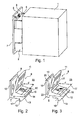
- FIG. 1 is a furniture body 1 with an outer drawer 2 with high drawer front 3 and an inner drawer 4 shown.
- the inner drawer 4 has a front element 5, the drawer front 3 and the front element 5 are coupled to one another via a coupling device 6.
- the coupling device 6 is in the FIGS. 2 and 3 shown in detail. The difference between the FIGS. 2 and 3 is that the coupling device 6 is adjusted to a different front element thickness d of the inner drawer.
- the front element thickness d of the front element 7 in FIG. 2 is smaller than the front element thickness d of the front element 8 according to FIG FIG. 3 ,
- the coupling device 6 comprises a base body 9 with a mounting portion 10 and an actuating element 11.
- the actuating element 11 is integrally connected to a cantilevered leg 12, on which an engagement element 13 is mounted.
- the leg 12 has a slot 14 through which a screw 15 engages, which is screwed into the engaging element 13. Via the slot 14, the engaging element 13 can be moved on the leg 12 and tuned to a thickness d of a front element 5, 7 or 8.
- the engagement element 13 is positioned on the leg 12 such that a projection 16 of the engagement element 13 can hook in precisely behind an inner edge 17 of the front element 5, 7 or 8.
- the coupling device 6 is at an inner side 18 of the drawer front 3 z. B. screwed over mounting holes 19, 20 in the attachment portion 10, which are accessible via access openings 21, 22 in the actuator 11.
- the actuating element 11 For coupling an inner drawer 4 or a front element 5, 7 or 8 from a not yet coupled state, the actuating element 11 is manually pressed, so that the engagement element 13 or the projection 16 is pivoted together with the actuating element 11 in the direction attachment section 10.
- the projection 16 lifts off from a perpendicular to the inside 18 of the shop front level, so that the projection 16 can be moved over an upper edge 23 of the front member 7, 8 away, until the Projection 16 has reached the edge 17 and can hook behind it by manually releasing the actuating portion 11, that is, for example, by removing a pressing there finger of an operator.
- a certain amount of play may be allowed to ensure a reliable hooking of the engaging element 13, taking into account different charging states of the inner and outer load in each situation.
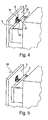
- the decoupling of the inner tray 4 of the outer tray 2 is in the process in the FIGS. 4 to 6 shown.
- the projection 16 of the coupling device 6 is raised and can be moved over the upper edge 23 of the front element 5 to the outside, which is indicated by the arrows 24 in the FIGS. 4, 5 and 6 is illustrated.
- FIG. 4 is the trigger position, in FIG. 5 an overflow position of the upper edge 23 and in FIG. 6 the free-standing positioning of the inner tray 4 of the outer tray 2 shown.
- FIG. 7 shows an embodiment in which instead of a front element 5, 7, 8 for coupling a mounted on the inner tray 4 railing 25 is used.
- the other components correspond to those according to Figure 1 to 6 with an adaptation of the engagement element 13 and the projection 16 to the round shape of the railing 25th
- FIGS. 8, 8a and 9 is another Embodiment of a coupling device 26 illustrated.
- the coupling device 26 is a pivot lever 27 with a hook extension 28 which engages in the coupled state, a bottom 29 of a front element 30 (see FIG. 8 ) and thereby couples the front element 30 to the shop front 3.
- the pivoting lever 27 has a pivot point e.g. in the form of an opening 31, which is penetrated by a screw for fixing the pivot lever, on an inner side 18 of the loading front 3, so that pivoted by the position of the pivot point of the pivot lever 27 due to gravity automatically in a position, the hook extension 28 behind wants to hook the bottom 29 of the front element 30.
- the pivoting lever 27 is pivoted out of the coupled, hooked-in position via a gripping extension 32, so that the inner drawer 4 can detach from the outer loading or loading front 3 (see FIG FIG. 9 ).
- stop screws 33, 34 are preferably provided which limit the decoupled state on the one hand (by the stopper screw 33) and on the other hand limit the coupled state (stop screw 34, see FIG. 9 ).
- stop screws 33, 34 are of course various other stop elements conceivable.
- FIGS. 10 and 11 show a coupling device 35 with a folding lever 36, in FIG. 10 in a coupled state, in FIG. 11 in a decoupled state, in FIG. 12a only the folding lever and in FIG. 12b a spring clip 37 as part of the coupling device.
- the folding lever 36 is made for example of a sheet metal part.
- the folding lever 36 comprises two elongated holes 38, 39. In the assembled state, the slots 38, 39 of screws 40, 41 (see FIGS. 10 and 11 ), wherein the screws 40, 41 in the material a drawer front 42 an outer drawer are screwed, so that the folding lever 36 can still move along the slots 38, 39.
- the folding lever 36 has the function of exerting a spring force between the front element 45 and the drawer front 42 when the drawer front 42 is coupled to a front element 45, so that the folding lever 36 only by acting on an operating portion 46 in the form of a folded end, from a coupled position ( please refer FIG. 10 ) and this is not done solely by gravity.
- a hook element 47 engages behind an underside of the front element 45.
- the folding lever 36 is moved downwards over the operating section 46, so that the inner drawer 4 can detach from the drawer front 42 and thus from the outer drawer and both trays can be moved independently of one another.
- the decoupled state is in FIG. 11 shown.
- the drawer front 42 of the external drawer is remote from the front element 45 of the inner drawer. 4
- FIGS. 13 and 14 show a coupling device 48, which consists only of a folding lever 49.
- the folding lever 49 has slots 50 and 51, through which the folding lever 49 can be mounted slidably via screws 52 and 53 on the inside of a drawer front 54.
- the folding lever 49 is mounted so that it engages only by gravity with a hook member 55, a front element 56 and thus connects an outer tray with an inner tray 4.
- the folding lever 49 can be raised manually above an operating section 57, so that the hook element 55 can be moved via a front element 56 of the inner drawer.
Landscapes
- Drawers Of Furniture (AREA)
Abstract
Description
- Die Erfindung betrifft eine Vorrichtung zur lösbaren Kopplung einer Innenlade an einer Außenlade eines Möbels nach dem Oberbegriff des Anspruchs 1 sowie ein Möbel mit einer solchen Vorrichtung.
- Bei bekannten Anordnungen, umfassend eine Außenlade mit zumindest einer Innenlade, kann die Innenlade mit der Außenlade wahlweise verbunden werden, so dass in einem gekoppelten Fall die Innenlade zusammen mit der Außenlade ausziehbar ist.
- Im anderen Fall ist die Innenlade von der Außenlade, gelöst, damit die Innenlade beim Ausziehen der Außenlade nicht gleichzeitig mitausgezogen wird.
- Aus der deutschen Gebrauchsmusterschrift
DE 20 2005 020 203 U1 ist ein Möbel mit einem Möbelkorpus und mit einer ersten und mindestens einer zweiten, relativ zum Möbelkorpus verfahrbaren Schublade bekannt, wobei in der Schließstellung der beiden Schubladen die Frontblende der ersten Schublade die Frontblende bzw. die Frontwand der zweiten Schublade im Wesentlichen vollständig bedeckt. Das Möbel ist mit einer lösbaren Kopplungsvorrichtung zum zeitweiligen Koppeln der beiden Schubladen ausgestattet. Die lösbare Kopplungsvorrichtung weist zumindest zwei vorwählbare Betriebsmodi auf, wobei in einem ersten Betriebsmodus die beiden Schubladen durch zumindest ein, vorzugsweise manuell, betätigbares Mitnehmerelement koppelbar sind und in einem zweiten Betriebsmodus die beiden Schubladen nicht gekoppelt sind. - Derartige Kopplungsvorrichtungen sind vergleichsweise aufwändig.
- Der Erfindung liegt die Aufgabe zugrunde, eine Vorrichtung der eingangs genannten Art vergleichsweise einfacher auszugestalten.
- Diese Aufgabe wird durch die Merkmale des Anspruchs 1 gelöst.
- In den abhängigen Ansprüchen sind vorteilhafte und zweckmäßige Weiterbildungen der Erfindung angegeben.
- Die Erfindung geht von einer Vorrichtung zur lösbaren Kopplung einer Innenlade an einer Außenlade eines Möbels aus, wobei die Vorrichtung ein Betätigungselement und ein bewegbares Eingreifelement aufweist und Anbringmittel umfasst. Vorzugsweise bedeckt eine Frontblende der Außenlade vollständig die Frontblende der Innenlade.
- Der Kern der Erfindung liegt darin, dass die Vorrichtung zur Anbringung an einer Innenseite einer Frontblende der Außenlade ausgebildet ist, und dass das Eingreifelement mit einem Mitnahmevorsprung zum Hintergreifen eines Frontelements einer Innenlade ausgebildet ist, wobei eine Position des Mitnahmevorsprungs für ein Hintergreifen eines Abschnitts des Frontelements der Innenlade einstellbar ist, und wobei der mitnehmende Vorsprung des Eingreifelements für ein Hintergreifen eines unvorbereiteten Abschnitts des Frontelements der Innenlade ausgebildet ist. Durch die Einstellbarkeit des Eingreifabschnitts ist zunächst dieser an einem vorgegebenen, hintergreifbaren Abschnitt einer Frontblende der Innenlade anpassbar. Des Weiteren ist keine Veränderung der Frontblende der Innenlade erforderlich, d.h. keine Anpassung der Frontblende auf einen Mitnahmevorsprung, so dass die Vorrichtung auch nachträglich in eine bestehende Lade ohne Zusatzaufwand nachgerüstet werden kann.
- In einer besonders vorteilhaften Ausgestaltung der Erfindung ist die Vorrichtung zur Anbringen an einer Innenseite einer Frontblende der Außenlade ohne separates Gegenstück an einem Frontelement der Innenlade als möglichem Träger ausgebildet. Damit kann die Vorrichtung für jede herkömmliche Lade ohne Anpassungsmaßnahmen an der Innenlade eingesetzt werden.
- In einer weiteren besonders vorteilhaften Ausgestaltung der Erfindung ist eine Position des Mitnahmevorsprungs am Eingreifelement einstellbar und fixierbar. Zum Beispiel ist an einem Entriegelungsorgan ein Mitnahmeteil mit Mitnahmevorsprung verschiebbar, vorzugsweise über ein Langloch, fixierbar.
- Die Fixierung kann z.B. mit einer Schraube erfolgen. Damit kann nach einer Montage der Vorrichtung an der Innenseite einer Frontblende eine Anpassung der Position des Mitnahmevorsprungs auf eine Wanddicke des Frontelements der Innenlade leicht angepasst werden.
- Im Weiteren ist es bevorzugt, wenn mit einem Federelement eine Mitnahmestellung des Eingreifelements, insbesondere des Mitnahmevorsprungs, vorgegeben ist. Das Federelement ist vorteilhafterweise so ausgestaltet, dass es den Mitnahmevorsprung in eine das Frontelement der Innenlade hintergreifende Position drängt. Dadurch bleibt ein gekoppelter Zustand so lange erhalten, bis insbesondere eine manuelle Entkopplung, d.h. ein Betätigen entgegen der Kraft des Federelements, stattfindet.
- In einer überdies vorteilhaften Ausführungsform der Erfindung umfasst die Vorrichtung ein Anbringelement, das zur Anbringung an einer ebenen Innenfläche einer Frontblende der Außenlade ausgebildet ist. Auf diese Weise lässt sich die Vorrichtung einfach an der Innenseite der Frontblende der Außenlade montieren, also z.B. auch nachträglich. Denn an der Frontblende sind keinerlei Anpassungsmaßnahmen erforderlich, es findet lediglich eine Montage an der bei gängigen Frontblenden ebenen Innenfläche statt.
- Darüber hinaus ist es bevorzugt, wenn zumindest ein Teil des Eingreifelements und des Betätigungselements als Abschnitte eines durchgängig zusammenhängenden und einheitlich aus einem Material hergestellten Körpers gebildet ist. Damit lässt sich ein einfacher Aufbau der erfindungsgemäßen Vorrichtung erzielen.
- In diesem Zusammenhang ist es bevorzugt, wenn lediglich ein Mitnahmeteil mit Mitnahmevorsprung als weiteres Teil, das vorzugsweise dann auch eine Einstellbarkeit der Position zum verbleibenden Teil ermöglicht, noch hinzukommt.
- In diesem Zusammenhang ist es bevorzugt, wenn das Anbringelement als Anbringabschnitt an dem Körper ausgebildet ist.
- In einer überdies bevorzugten Ausgestaltung der Erfindung ist zwischen dem Anbringabschnitt und dem Eingreifabschnitt ein Verbindungsabschnitt ausgebildet, der elastisch biegsam ist. Damit lässt sich ein Federelement realisieren, das den Eingreif abschnitt z.B. in eine das Frontelement der Innenlade hintergreifende Position drängt. Zum Beispiel wird ein verringerter Materialquerschnitt genutzt, um ein Federelement zu realisieren, ohne dass eine Materialänderung des sonst zusammenhängenden und einheitlichen Körpers notwendig ist. Der verringerte Materialabschnitt wirkt vorzugsweise wie eine Art "Filmscharnier", weist jedoch ausreichende Rückstellkräfte auf, wenn der Eingreifabschnitt z. B. in eine Position gebracht wird, in welcher ein Entkoppeln von Außen- und Innenlade möglich ist, nachdem die manuelle Betätigung nicht mehr stattfindet, wodurch sich der Eingreifabschnitt in eine Ausgangslage zurückbewegt, die in einem gekoppelten Zustand die Kopplungsposition sicherstellt.
- In einer weiteren bevorzugten Ausgestaltung der Erfindung ist der Körper ein Blechstreifen.
- Zum Beispiel ist das Betätigungselement durch eine oder mehrere Biegungen des Blechstreifens realisiert. Vorzugsweise ist das Eingreifelement durch eine oder mehrere Biegungen des Blechstreifens ausgebildet. Damit lässt sich auf einfach Weise eine erfindungsgemäße Vorrichtung realisieren.
- Um eine einfache Anbringung einer Vorrichtung aus einem Blechstreifen realisieren zu können, wird im Weiteren vorgeschlagen, dass der Blechstreifen zwischen dem Betätigungselement und dem Eingreifelement als Anbringabschnitt ausgebildet ist. Dieser Anbringabschnitt kann z. B. an eine ebene Fläche einer Innenseite einer Frontblende der Außenlade montiert werden.
- In einer außerdem bevorzugten Ausgestaltung der Erfindung ist am Anbringabschnitt eine Ausnehmung für ein Befestigungselement ausgebildet, mit der der Anbringabschnitt an der Innenseite der Frontblende der Außenlade anbringbar und geführt bewegbar ist. Zum Beispiel ist für eine Schwenkbewegung ein kreisförmiges Loch vorgesehen. Um eine lineare Verschiebung zu ermöglichen, wird vorteilhafterweise ein Langloch eingesetzt. Das Langloch kann z.B. bei nicht vollkommen angezogener Montageschraube als Führungskulisse für die Vorrichtung genutzt werden, um die Vorrichtung von einer eine Frontblende der Innenlade hintergreifenden Position in eine Position zu bringen, in welcher eine Entkopplung stattfindet.
- Anstatt aus einem Blechstreifen kann der Körper auch ein Gusskörper und/oder Stanzkörper sein, z.B. aus Metall und/oder Kunststoff.
- Um eine definierte Positionierung der Vorrichtung zu ermöglichen, wird im Weiteren vorgeschlagen, dass ein Anschlag vorgesehen ist, durch den eine Bewegung eines Betätigungselements der Vorrichtung begrenzt ist.
- Mehrere Ausführungsbeispiele der Erfindung sind in den Zeichnungen dargestellt und werden unter Angabe weiterer Vorteile und Einzelheiten nachstehend näher erläutert. Es zeigen
- Figur 1
- in perspektivischer Ansicht ein Möbelkorpus mit Außen- und Innenlade, die aneinander über eine Koppelvorrichtung gekoppelt sind,
- Figur 2
- in perspektivischer Teilansicht eine Koppelvorrichtung, eingehakt an einer Frontblende,
- Figur 3
- eine zu
Figur 2 entsprechende Ausführungsform, jedoch mit einem anderen Frontelement, - Figur 4
- in perspektivischer Teilansicht eine Außenlade mit Koppelvorrichtung im Moment der Entkopplung von einer Innenlade,
- Figur 5
- die Ausführungsform nach
Figur 4 in einem Zustand, in welchem sich die Außenlade von der Innenlade bereits etwas entfernt hat, - Figur 6
- die Ausführungsform nach
Figur 4 in einem entkoppelten Zustand, - Figur 7
- eine weitere Ausführungsform der Erfindung in einer perspektivischen Teilansicht im gekoppelten Zustand,
- Figur 8
- in einer perspektivischen Teilansicht eine weitere Ausführungsform einer erfindungsgemäßen Koppelvorrichtung im gekoppelten Zustand,
- Figur 8a
- die Koppelvorrichtung von
Figur 8 in perspektivischer Ansicht, - Figur 9
- in ebenfalls einer perspektivischen Ansicht, jedoch von
Figur 8 abweichenden Perspektive, die Ausführungsform vonFigur 8 im entkoppelten Zustand einer Außenlade von einer Innenlade, - Figur 10
- in einer schematischen Teilansicht von der Seite eine Außenlade, gekoppelt an eine Innenlade über eine weitere Ausgestaltung einer erfindungsgemäßen Koppelvorrichtung,
- Figur 11
- die Koppelvorrichtung im entkoppelten Zustand in perspektivischen Ansicht, montiert an der Innenseite einer Außenblende,
- Figur 12a
- ein Hauptteil der Koppelvorrichtung aus
Figur 10 und 11 in perspektivischer Ansicht, - Figur 12b
- ein Federelement der Koppelvorrichtung nach
Figur 10 und 11 in perspektivischer Ansicht, - Figur 13
- in perspektivischer Teilansicht eine Außenblende einer Außenlade, gekoppelt an einer Frontblende einer Innenlade über eine weitere erfindungsgemäße Koppelvorrichtung und
- Figur 14
- die Koppelvorrichtung aus
Figur 13 in perspektivischer Ansicht in Alleinstellung. - In
Figur 1 ist ein Möbelkorpus 1 mit einer Außenlade 2 mit hoher Schubladenfront 3 und einer Innenlade 4 abgebildet. Die Innenlade 4 hat ein Frontelement 5, die Schubladenfront 3 und das Frontelement 5 sind über eine Koppelvorrichtung 6 miteinander gekoppelt. - Die Koppelvorrichtung 6 ist in den
Figuren 2 und 3 im Detail abgebildet. Der Unterschied zwischen denFiguren 2 und 3 besteht darin, dass die Koppelvorrichtung 6 auf eine unterschiedliche Frontelementdicke d der Innenlade justiert ist. Die Frontelementdicke d des Frontelements 7 inFigur 2 ist kleiner als die Frontelementdicke d des Frontelements 8 gemäßFigur 3 . - Die Koppelvorrichtung 6 umfasst einen Grundkörper 9 mit einem Anbringabschnitt 10 und einem Betätigungselement 11. Das Betätigungselement 11 ist einstückig mit einem auskragenden Schenkel 12 verbunden, an dem ein Eingreifelement 13 montiert ist. Zur Montage des Eingreifelements 13 besitzt der Schenkel 12 ein Langloch 14, durch das eine Schraube 15 greift, die in das Eingreifelement 13 eingeschraubt ist. Über das Langloch 14 lässt sich das Eingreifelement 13 am Schenkel 12 verschieben und auf eine Dicke d eines Frontelements 5, 7 oder 8 abstimmen. Dazu wird das Eingreifelement 13 am Schenkel 12 so positioniert, dass ein Vorsprung 16 des Eingreifelements 13 passgenau hinter eine innen liegende Kante 17 des Frontelements 5, 7 oder 8 einhaken kann.
- Die Koppelvorrichtung 6 wird an einer Innenseite 18 der Schubladenfront 3 z. B. angeschraubt über Montagelöcher 19, 20 im Anbringabschnitt 10, die über Zugangsöffnungen 21, 22 im Betätigungselement 11 erreichbar sind.
- Zum Ankoppeln einer Innenlade 4 bzw. eines Frontelements 5, 7 oder 8 aus einem noch nicht gekoppelten Zustand wird manuell das Betätigungselement 11 gedrückt, so dass das Eingreifelement 13 bzw. der Vorsprung 16 mit dem Betätigungselement 11 zusammen in Richtung Anbringabschnitt 10 geschwenkt wird. Dadurch hebt der Vorsprung 16 aus einer senkrecht zur Innenseite 18 der Ladenfront stehenden Ebene ab, so dass der Vorsprung 16 über eine Oberkante 23 des Frontelements 7, 8 hinweg bewegt werden kann, bis der Vorsprung 16 die Kante 17 erreicht hat und dahinter einhaken kann durch manuelles Freigeben des Betätigungsabschnitts 11, d.h. zum Beispiel durch Wegnahme eines dort drückenden Fingers einer Bedienperson.
- Passgenau heißt im Sinne der Erfindung, dass im gekoppelten Zustand möglichst wenig Spiel zwischen Vorsprung 16 und Vorderkante 17 besteht, wenn das Frontelement 5, 7, 8 an der Innenseite der Ladenfront 3 anliegt.
- Ein gewisses Spiel kann zugestanden werden, um ein zuverlässiges Einhaken des Eingreifelements 13 unter Berücksichtigung von unterschiedlichen Ladezuständen der Innen- und Außenlade in jeder Situation zu gewährleisten.
- Ggf. kann auch ein Nachjustieren des Eingreifelements 13 durch Lösen der Schraube 15 und anschließendem Fixieren der Schraube 15 stattfinden, wenn sich z.B. der Ladezustand der Schubladen drastisch ändert.
- Das Entkoppeln der Innenlade 4 von der Außenlade 2 ist im Ablauf in den
Figuren 4 bis 6 dargestellt. Durch manuelles Drücken des Betätigungselements 11 wird der Vorsprung 16 der Koppelvorrichtung 6 angehoben und kann über die Oberkante 23 des Frontelements 5 nach außen hinweg bewegt werden, was durch die Pfeile 24 in denFiguren 4, 5 und6 veranschaulicht ist. InFigur 4 ist die Auslösestellung, inFigur 5 eine Überfahrstellung der Oberkante 23 und inFigur 6 die freistehende Positionierung der Innenlade 4 von der Außenlade 2 dargestellt. -
Figur 7 zeigt ein Ausführungsbeispiel, bei welchem anstatt eines Frontelements 5, 7, 8 zur Ankoppelung eine an der Innenlade 4 angebrachte Reling 25 genutzt wird. Die übrigen Bauteile entsprechen denen gemäßFigur 1 bis 6 mit einer Anpassung des Eingreifelements 13 und des Vorsprungs 16 an die runde Form der Reling 25. - In den
Figuren 8, 8a und 9 ist ein weiteres Ausführungsbeispiel einer Koppelvorrichtung 26 veranschaulicht. Bei der Koppelvorrichtung 26 handelt es sich um einen Schwenkhebel 27 mit einem Hakenfortsatz 28, der im gekoppelten Zustand eine Unterseite 29 eines Frontelements 30 hintergreift (sieheFigur 8 ) und dadurch das Frontelement 30 mit der Ladenfront 3 koppelt. - Der Schwenkhebel 27 weist einen Schwenkpunkt z.B. in Form einer Öffnung 31 auf, die zur Fixierung des Schwenkhebels von einer Schraube durchgriffen wird, an einer Innenseite 18 der Ladenfront 3, so dass durch die Lage des Schwenkpunktes der Schwenkhebel 27 aufgrund der Schwerkraft automatisch in eine Position verschwenkt, wobei der Hakenfortsatz 28 hinter der Unterseite 29 des Frontelements 30 einhaken will.
- Um die Kopplung zu lösen, wird über einen Greiffortsatz 32 der Schwenkhebel 27 aus der gekoppelten, eingehakten Position verschwenkt, so dass sich die Innenlade 4 von der Außenlade bzw. Ladenfront 3 lösen kann (siehe
Figur 9 ). - Damit der Schwenkhebel 27 keine undefinierten Positionen einnimmt, sind vorzugsweise Anschlagschrauben 33, 34 vorgesehen, die einerseits den ausgekoppelten Zustand limitieren (durch die Anschlagschraube 33) und andererseits den gekoppelten Zustand eingrenzen (Anschlagschraube 34, siehe hierzu
Figur 9 ). - Anstatt der Anschlagschrauben 33, 34 sind selbstverständlich verschiedene andere Anschlagelemente denkbar.
- Die
Figuren 10, 11, 12a und 12b zeigen eine Koppelvorrichtung 35 mit einem Falthebel 36, inFigur 10 in einem gekoppelten Zustand, inFigur 11 in einem entkoppelten Zustand, inFigur 12a lediglich den Falthebel und inFigur 12b eine Federspange 37 als Teil der Koppelvorrichtung. Der Falthebel 36 ist z.B. aus einem Blechteil gefertigt. Der Falthebel 36 umfasst zwei Langlöcher 38, 39. Im montierten Zustand werden die Langlöcher 38, 39 von Schrauben 40, 41 (sieheFigur 10 und 11 ) durchgegriffen, wobei die Schrauben 40, 41 in das Material einer Schubladenfront 42 einer Außenlade eingeschraubt werden, so dass sich der Falthebel 36 jedoch noch entlang der Langlöcher 38, 39 verschieben lässt. - Am Falthebel ist die Federspange 37 über umgebogene Enden 43 in passenden Ausnehmungen 44 des Falthebels 36 eingehakt. Der Falthebel 36 hat die Funktion, beim Aneinanderkoppeln der Schubladenfront 42 an ein Frontelement 45 eine Federkraft zwischen Frontelement 45 und Schubladenfront 42 auszuüben, so dass sich der Falthebel 36 nur durch Einwirkung auf einen Bedienabschnitt 46 in Form eines umgekanteten Endes, aus einer gekoppelten Position (siehe
Figur 10 ) entkoppeln lässt und dies nicht lediglich durch die Schwerkraft erfolgt. - Im eingekoppelten Zustand hintergreift ein Hakenelement 47 eine Unterseite des Frontelements 45. Damit laufen Außenlade und Innenlade gemeinsam. Zum Entkoppeln wird über den Bedienabschnitt 46 der Falthebel 36 nach unten verschoben, so dass sich die Innenlade 4 von der Schubladenfront 42 und damit von der Außenlade lösen kann und beide Laden unabhängig voneinander bewegbar sind. Der entkoppelte Zustand ist in
Figur 11 dargestellt. Die Schubladenfront 42 der Außenlade steht entfernt von dem Frontelement 45 der Innenlade 4. - Die
Figuren 13 und 14 zeigen eine Koppelvorrichtung 48, die lediglich aus einem Falthebel 49 besteht. Der Falthebel 49 weist Langlöcher 50 und 51 auf, durch die der Falthebel 49 verschiebbar über Schrauben 52 und 53 an der Innenseite einer Schubladenfront 54 montierbar ist. Der Falthebel 49 wird so montiert, dass er lediglich durch Schwerkraft mit einem Hakenelement 55 ein Frontelement 56 hintergreift und damit eine Außenlade mit einer Innenlade 4 verbindet. Um die Innenlade 4 von der Schubladenfront 54 zu entkoppeln, kann manuell über einen Bedienabschnitt 57 der Falthebel 49 nach oben angehoben werden, so dass das Hakenelement 55 über ein Frontelement 56 der Innenlade bewegt werden kann. -
- 1
- Möbelkorpus
- 2
- Außenlade
- 3
- Schubladenfront
- 4
- Innenlade
- 5
- Frontelement
- 6
- Koppelvorrichtung
- 7
- Frontelement
- 8
- Frontelement
- 9
- Grundkörper
- 10
- Anbringabschnitt
- 11
- Betätigungselement
- 12
- Schenkel
- 13
- Eingreifelement
- 14
- Langloch
- 15
- Schraube
- 16
- Vorsprung
- 17
- Kante
- 18
- Innenseite
- 19
- Montageloch
- 20
- Montageloch
- 21
- Zugangsöffnung
- 22
- Zugangsöffnung
- 23
- Oberkante
- 24
- Pfeil
- 25
- Reling
- 26
- Koppelvorrichtung
- 27
- Schwenkhebel
- 28
- Hakenfortsatz
- 29
- Unterseite
- 30
- Frontelement
- 31
- Öffnung
- 32
- Greiffortsatz
- 33
- Anschlagschraube
- 34
- Anschlagschraube
- 35
- Koppelvorrichtung
- 36
- Falthebel
- 37
- Federspange
- 38
- Langloch
- 39
- Langloch
- 40
- Schraube
- 41
- Schraube
- 42
- Schubladenfront
- 43
- Ende
- 44
- Ausnehmung
- 45
- Frontelement
- 46
- Bedienabschnitt
- 47
- Hakenelement
- 48
- Koppelvorrichtung
- 49
- Falthebel
- 50
- Langloch
- 51
- Langloch
- 52
- Schraube
- 53
- Schraube
- 54
- Schubladenfront
- 55
- Hakenelement
- 56
- Frontelement
- 57
- Bedienabschnitt
Claims (16)
- Vorrichtung zur lösbaren Kopplung einer Innenlade (4) an einer Außenlade (2) eines Möbels, wobei die Vorrichtung ein Betätigungselement (11) und ein bewegbares Eingreifelement (13) aufweist und Anbringmittel umfasst, dadurch gekennzeichnet, dass die Vorrichtung zur Anbringung an einer Innenseite einer Frontblende (7) der Außenlade (2) ausgebildet ist, und dass das Eingreifelement (13) mit einem Mitnahmevorsprung (16) zum Hintergreifen eines Frontelements (5) der Innenlade (4) ausgebildet ist, wobei eine Position des Mitnahmevorsprungs (16) für ein Hintergreifen eines Abschnitts des Frontelements (5) der Innenlade (4) einstellbar ist, und wobei der mitnehmende Vorsprung (16) des Eingreifelements (13) für ein Hintergreifen eines unvorbereiteten Abschnitts des Frontelements (5) der Innenlade (4) ausgebildet ist.
- Vorrichtung nach Anspruch 1, dadurch gekennzeichnet, dass die Vorrichtung zur Anbringung an einer Innenseite einer Frontblende (7) der Außenlade (2) ohne separates Gegenstück an einem Frontelement (5) der Innenlade (4) als möglichem Träger ausgebildet ist.
- Vorrichtung nach einem der vorgenannten Ansprüche, dadurch gekennzeichnet, dass eine Position des Mitnahmevorsprungs (16) am Eingreifelement (13) fixierbar ist.
- Vorrichtung nach einem der vorgenannten Ansprüche, dadurch gekennzeichnet, dass mit einem Federelement eine Mitnahmestellung des Eingreifelements, insbesondere des Mitnahmevorsprungs (47, 55) vorgegeben ist.
- Vorrichtung nach einem der vorgenannten Ansprüche, dadurch gekennzeichnet, dass die Vorrichtung ein Anbringelement (10, 36, 49) umfasst, das zur Anbringung an einer ebenen Innenfläche einer Frontblende (7, 42, 54) der Außenlade (2) ausgebildet ist.
- Vorrichtung nach einem der vorgenannten Ansprüche, dadurch gekennzeichnet, dass zumindest ein Teil des Eingreifelements (13, 36, 49) und des Betätigungselements (11) als Abschnitte eines durchgehend zusammenhängenden und einheitlich aus einem Material hergestellten Körpers gebildet ist.
- Vorrichtung nach Anspruch 5, dadurch gekennzeichnet, dass das Anbringelement als Anbringabschnitt an dem Körper ausgebildet ist.
- Vorrichtung nach Anspruch 6, dadurch gekennzeichnet, dass zwischen dem Anbringabschnitt und dem Eingreifabschnitt ein Verbindungsabschnitt ausgebildet ist, der elastisch biegsam ist.
- Vorrichtung nach einem der Ansprüche 6 bis 8, dadurch gekennzeichnet, dass der Körper ein Blechstreifen ist.
- Vorrichtung nach Anspruch 9, dadurch gekennzeichnet, dass das Betätigungselement (46, 57) durch ein oder mehrere Biegungen des Blechstreifens ausgebildet ist.
- Vorrichtung nach Anspruch 9 oder 10, dadurch gekennzeichnet, dass das Eingreifelement durch eine oder mehrere Biegungen des Blechstreifens ausgebildet ist.
- Vorrichtung nach einem der Ansprüche 9 bis 11, dadurch gekennzeichnet, dass der Blechstreifen zwischen dem Betätigungselement (46, 57) und dem Eingreifelement als Anbringabschnitt ausgebildet ist.
- Vorrichtung nach Anspruch 12, dadurch gekennzeichnet, dass am Anbringabschnitt eine Ausnehmung (20, 31, 38, 39, 50, 51) für ein Befestigungselement ausgebildet ist, mit der der Anbringabschnitt an der Innenseite (18) der Frontblende (7, 42, 54) der Außenlade (2) anbringbar und geführt bewegbar ist.
- Vorrichtung nach einem der Ansprüche 6 bis 8, dadurch gekennzeichnet, dass der Körper ein Gusskörper und/oder Stanzkörper ist.
- Vorrichtung nach einem der vorgenannten Ansprüche, dadurch gekennzeichnet, dass ein Anschlag (33, 34) vorgesehen ist, durch den eine Bewegung eines Betätigungselements (27) begrenzt ist.
- Möbel mit einer Vorrichtung nach einem der vorgenannten Ansprüche 1 bis 15.
Applications Claiming Priority (1)
| Application Number | Priority Date | Filing Date | Title |
|---|---|---|---|
| DE202012012266.5U DE202012012266U1 (de) | 2012-12-21 | 2012-12-21 | Vorrichtung zur lösbaren Kopplung einer Innenlade an einer Außenlade eines Möbels sowie Möbel |
Publications (2)
| Publication Number | Publication Date |
|---|---|
| EP2745736A1 true EP2745736A1 (de) | 2014-06-25 |
| EP2745736B1 EP2745736B1 (de) | 2020-09-23 |
Family
ID=49884870
Family Applications (1)
| Application Number | Title | Priority Date | Filing Date |
|---|---|---|---|
| EP13005922.3A Active EP2745736B1 (de) | 2012-12-21 | 2013-12-19 | Vorrichtung zur lösbaren Kopplung einer Innenlade an einer Außenlade eines Möbels sowie Möbel |
Country Status (2)
| Country | Link |
|---|---|
| EP (1) | EP2745736B1 (de) |
| DE (1) | DE202012012266U1 (de) |
Cited By (3)
| Publication number | Priority date | Publication date | Assignee | Title |
|---|---|---|---|---|
| WO2020258594A1 (zh) * | 2019-06-27 | 2020-12-30 | 青岛海尔电冰箱有限公司 | 冰箱抽屉及冰箱 |
| CN113243685A (zh) * | 2021-06-04 | 2021-08-13 | 广东东泰五金精密制造有限公司 | 一种联动开闭锁离装置及其家具抽屉 |
| CN117860056A (zh) * | 2023-12-26 | 2024-04-12 | 广东爱加精密五金制品有限公司 | 一种内外抽屉联动结构与抽屉 |
Families Citing this family (3)
| Publication number | Priority date | Publication date | Assignee | Title |
|---|---|---|---|---|
| DE202014102934U1 (de) * | 2014-06-27 | 2015-10-02 | Grass Gmbh | Vorrichtung zur lösbaren Kopplung einer Außenlade mit einer Innenlade sowie ein Möbel |
| JP7164146B2 (ja) * | 2018-04-21 | 2022-11-01 | 太陽パーツ株式会社 | 引出構造およびキャビネット |
| DE102022108610A1 (de) | 2022-04-08 | 2023-10-12 | Paul Hettich Gmbh & Co. Kg | Möbel |
Citations (5)
| Publication number | Priority date | Publication date | Assignee | Title |
|---|---|---|---|---|
| DE8802343U1 (de) * | 1988-02-23 | 1988-03-31 | SieMatic Möbelwerke GmbH & Co, 4972 Löhne | Auszug mit ankoppelbarem Schubkasten |
| DE202005020203U1 (de) | 2005-02-11 | 2006-03-02 | Julius Blum Gmbh | Möbel |
| DE202006011311U1 (de) * | 2006-07-22 | 2007-11-29 | SieMatic Möbelwerke GmbH & Co. KG | Schubladenanordnung |
| DE202010005503U1 (de) * | 2010-05-26 | 2011-10-05 | Ninkaplast Gmbh | Kupplungseinrichtung für Möbelauszüge |
| DE102010017132A1 (de) * | 2010-05-28 | 2011-12-01 | Paul Hettich Gmbh & Co. Kg | Schrankmöbel mit einem Frontschubkasten und einem Innenschubkasten |
Family Cites Families (1)
| Publication number | Priority date | Publication date | Assignee | Title |
|---|---|---|---|---|
| DE202007009324U1 (de) * | 2007-07-03 | 2008-11-13 | Ninkaplast Gmbh | Kupplungseinrichtung für Möbelauszüge |
-
2012
- 2012-12-21 DE DE202012012266.5U patent/DE202012012266U1/de not_active Expired - Lifetime
-
2013
- 2013-12-19 EP EP13005922.3A patent/EP2745736B1/de active Active
Patent Citations (5)
| Publication number | Priority date | Publication date | Assignee | Title |
|---|---|---|---|---|
| DE8802343U1 (de) * | 1988-02-23 | 1988-03-31 | SieMatic Möbelwerke GmbH & Co, 4972 Löhne | Auszug mit ankoppelbarem Schubkasten |
| DE202005020203U1 (de) | 2005-02-11 | 2006-03-02 | Julius Blum Gmbh | Möbel |
| DE202006011311U1 (de) * | 2006-07-22 | 2007-11-29 | SieMatic Möbelwerke GmbH & Co. KG | Schubladenanordnung |
| DE202010005503U1 (de) * | 2010-05-26 | 2011-10-05 | Ninkaplast Gmbh | Kupplungseinrichtung für Möbelauszüge |
| DE102010017132A1 (de) * | 2010-05-28 | 2011-12-01 | Paul Hettich Gmbh & Co. Kg | Schrankmöbel mit einem Frontschubkasten und einem Innenschubkasten |
Cited By (4)
| Publication number | Priority date | Publication date | Assignee | Title |
|---|---|---|---|---|
| WO2020258594A1 (zh) * | 2019-06-27 | 2020-12-30 | 青岛海尔电冰箱有限公司 | 冰箱抽屉及冰箱 |
| US11867455B2 (en) | 2019-06-27 | 2024-01-09 | Qingdao Haier Refrigerator Co., Ltd. | Refrigerator drawer and refrigerator |
| CN113243685A (zh) * | 2021-06-04 | 2021-08-13 | 广东东泰五金精密制造有限公司 | 一种联动开闭锁离装置及其家具抽屉 |
| CN117860056A (zh) * | 2023-12-26 | 2024-04-12 | 广东爱加精密五金制品有限公司 | 一种内外抽屉联动结构与抽屉 |
Also Published As
| Publication number | Publication date |
|---|---|
| DE202012012266U1 (de) | 2014-03-24 |
| EP2745736B1 (de) | 2020-09-23 |
Similar Documents
| Publication | Publication Date | Title |
|---|---|---|
| EP2745736B1 (de) | Vorrichtung zur lösbaren Kopplung einer Innenlade an einer Außenlade eines Möbels sowie Möbel | |
| EP2336705B1 (de) | Magazinhalter | |
| EP3132713B1 (de) | Vorrichtung zum bewegen eines bewegbaren möbelteils und möbel | |
| EP3727090B1 (de) | Schubladenseitenwand mit einem abdeckprofil | |
| EP2750549B1 (de) | Schublade | |
| DE112013007025B4 (de) | Verriegelungsvorrichtung für teleskopierbare Möbelsäule, Möbel und Verfahren | |
| EP2052120A1 (de) | Griffschale zum einklipsen in einem durchbruch in einer dünnen wand | |
| DE202004002321U1 (de) | Positioniervorrichtung für eine Mehrsegment-Gleitschieneneinrichtung für Schubladen | |
| WO2009092741A1 (de) | Beschlagteil zur befestigung an einem koch- oder bratgefäss | |
| DE2740200A1 (de) | Sicherheitsgurtschloss | |
| EP3684223B1 (de) | Kupplungsvorrichtung für schubkasten mit nachverrastung | |
| WO2020157180A1 (de) | Klappenbeschlag für ein möbel | |
| EP3773074B1 (de) | Schubsystem mit auszugsführung an welchem unterschiedliche schubkastensystemen montierbar sind | |
| EP2853665B1 (de) | Türgriff | |
| EP1297765B1 (de) | Vorrichtung zur werkzeuglosen Montage und Demontage der Schubladenfront von Möbeln | |
| EP2843164B1 (de) | Beschlag für ein Schubladenmodul eines mobilen Fahrzeuges | |
| DE4013158C2 (de) | Abdeckrollo für Kraftfahrzeuge | |
| EP2233039B1 (de) | Schubkastenführung | |
| EP1504696A2 (de) | Schrankelement mit einem selbsttätig ausfahrbaren Schubkasten sowie betätigungsvorrichtung für einen solchen Schubkasten | |
| DE102014100414B4 (de) | Dunstabzugshaubeneinrichtung | |
| EP3860400B1 (de) | Befestigungsvorrichtung für eine blende eines schubkastens an einer zarge | |
| DE202013008886U1 (de) | Schiebeschaftinstrument | |
| DE2739889C3 (de) | Halteclip aus Kunststoff zur Befestigung eines Gegenstandes an einem mit einem T-Bolzen versehenen Träger | |
| DE202008008753U1 (de) | Vorrichtung zum Bewegen eines bewegbaren Möbelteils relativ zu einem feststehenden Möbelteil | |
| EP2730196B1 (de) | Vorrichtung zur Verbindung der Front eines bewegbaren Möbelteils mit dessen Seitenteil |
Legal Events
| Date | Code | Title | Description |
|---|---|---|---|
| PUAI | Public reference made under article 153(3) epc to a published international application that has entered the european phase |
Free format text: ORIGINAL CODE: 0009012 |
|
| 17P | Request for examination filed |
Effective date: 20131219 |
|
| AK | Designated contracting states |
Kind code of ref document: A1 Designated state(s): AL AT BE BG CH CY CZ DE DK EE ES FI FR GB GR HR HU IE IS IT LI LT LU LV MC MK MT NL NO PL PT RO RS SE SI SK SM TR |
|
| AX | Request for extension of the european patent |
Extension state: BA ME |
|
| R17P | Request for examination filed (corrected) |
Effective date: 20141223 |
|
| RBV | Designated contracting states (corrected) |
Designated state(s): AL AT BE BG CH CY CZ DE DK EE ES FI FR GB GR HR HU IE IS IT LI LT LU LV MC MK MT NL NO PL PT RO RS SE SI SK SM TR |
|
| STAA | Information on the status of an ep patent application or granted ep patent |
Free format text: STATUS: EXAMINATION IS IN PROGRESS |
|
| 17Q | First examination report despatched |
Effective date: 20161212 |
|
| APBK | Appeal reference recorded |
Free format text: ORIGINAL CODE: EPIDOSNREFNE |
|
| APBN | Date of receipt of notice of appeal recorded |
Free format text: ORIGINAL CODE: EPIDOSNNOA2E |
|
| APBR | Date of receipt of statement of grounds of appeal recorded |
Free format text: ORIGINAL CODE: EPIDOSNNOA3E |
|
| APAF | Appeal reference modified |
Free format text: ORIGINAL CODE: EPIDOSCREFNE |
|
| APAF | Appeal reference modified |
Free format text: ORIGINAL CODE: EPIDOSCREFNE |
|
| APAF | Appeal reference modified |
Free format text: ORIGINAL CODE: EPIDOSCREFNE |
|
| APBX | Invitation to file observations in appeal sent |
Free format text: ORIGINAL CODE: EPIDOSNOBA2E |
|
| APBZ | Receipt of observations in appeal recorded |
Free format text: ORIGINAL CODE: EPIDOSNOBA4E |
|
| APBT | Appeal procedure closed |
Free format text: ORIGINAL CODE: EPIDOSNNOA9E |
|
| RIN1 | Information on inventor provided before grant (corrected) |
Inventor name: REMO, EGGER Inventor name: GUENTER, GRABHER |
|
| GRAJ | Information related to disapproval of communication of intention to grant by the applicant or resumption of examination proceedings by the epo deleted |
Free format text: ORIGINAL CODE: EPIDOSDIGR1 |
|
| GRAP | Despatch of communication of intention to grant a patent |
Free format text: ORIGINAL CODE: EPIDOSNIGR1 |
|
| REG | Reference to a national code |
Ref country code: DE Ref legal event code: R079 Ref document number: 502013015142 Country of ref document: DE Free format text: PREVIOUS MAIN CLASS: A47B0088020000 Ipc: A47B0088750000 |
|
| GRAP | Despatch of communication of intention to grant a patent |
Free format text: ORIGINAL CODE: EPIDOSNIGR1 |
|
| STAA | Information on the status of an ep patent application or granted ep patent |
Free format text: STATUS: GRANT OF PATENT IS INTENDED |
|
| INTG | Intention to grant announced |
Effective date: 20200519 |
|
| RIC1 | Information provided on ipc code assigned before grant |
Ipc: A47B 88/75 20170101AFI20200512BHEP |
|
| GRAS | Grant fee paid |
Free format text: ORIGINAL CODE: EPIDOSNIGR3 |
|
| GRAA | (expected) grant |
Free format text: ORIGINAL CODE: 0009210 |
|
| STAA | Information on the status of an ep patent application or granted ep patent |
Free format text: STATUS: THE PATENT HAS BEEN GRANTED |
|
| AK | Designated contracting states |
Kind code of ref document: B1 Designated state(s): AL AT BE BG CH CY CZ DE DK EE ES FI FR GB GR HR HU IE IS IT LI LT LU LV MC MK MT NL NO PL PT RO RS SE SI SK SM TR |
|
| REG | Reference to a national code |
Ref country code: GB Ref legal event code: FG4D Free format text: NOT ENGLISH |
|
| REG | Reference to a national code |
Ref country code: CH Ref legal event code: EP |
|
| REG | Reference to a national code |
Ref country code: DE Ref legal event code: R096 Ref document number: 502013015142 Country of ref document: DE |
|
| REG | Reference to a national code |
Ref country code: IE Ref legal event code: FG4D Free format text: LANGUAGE OF EP DOCUMENT: GERMAN |
|
| REG | Reference to a national code |
Ref country code: AT Ref legal event code: REF Ref document number: 1315492 Country of ref document: AT Kind code of ref document: T Effective date: 20201015 |
|
| PG25 | Lapsed in a contracting state [announced via postgrant information from national office to epo] |
Ref country code: HR Free format text: LAPSE BECAUSE OF FAILURE TO SUBMIT A TRANSLATION OF THE DESCRIPTION OR TO PAY THE FEE WITHIN THE PRESCRIBED TIME-LIMIT Effective date: 20200923 Ref country code: FI Free format text: LAPSE BECAUSE OF FAILURE TO SUBMIT A TRANSLATION OF THE DESCRIPTION OR TO PAY THE FEE WITHIN THE PRESCRIBED TIME-LIMIT Effective date: 20200923 Ref country code: NO Free format text: LAPSE BECAUSE OF FAILURE TO SUBMIT A TRANSLATION OF THE DESCRIPTION OR TO PAY THE FEE WITHIN THE PRESCRIBED TIME-LIMIT Effective date: 20201223 Ref country code: GR Free format text: LAPSE BECAUSE OF FAILURE TO SUBMIT A TRANSLATION OF THE DESCRIPTION OR TO PAY THE FEE WITHIN THE PRESCRIBED TIME-LIMIT Effective date: 20201224 Ref country code: BG Free format text: LAPSE BECAUSE OF FAILURE TO SUBMIT A TRANSLATION OF THE DESCRIPTION OR TO PAY THE FEE WITHIN THE PRESCRIBED TIME-LIMIT Effective date: 20201223 Ref country code: SE Free format text: LAPSE BECAUSE OF FAILURE TO SUBMIT A TRANSLATION OF THE DESCRIPTION OR TO PAY THE FEE WITHIN THE PRESCRIBED TIME-LIMIT Effective date: 20200923 |
|
| PG25 | Lapsed in a contracting state [announced via postgrant information from national office to epo] |
Ref country code: RS Free format text: LAPSE BECAUSE OF FAILURE TO SUBMIT A TRANSLATION OF THE DESCRIPTION OR TO PAY THE FEE WITHIN THE PRESCRIBED TIME-LIMIT Effective date: 20200923 Ref country code: LV Free format text: LAPSE BECAUSE OF FAILURE TO SUBMIT A TRANSLATION OF THE DESCRIPTION OR TO PAY THE FEE WITHIN THE PRESCRIBED TIME-LIMIT Effective date: 20200923 |
|
| REG | Reference to a national code |
Ref country code: NL Ref legal event code: MP Effective date: 20200923 |
|
| REG | Reference to a national code |
Ref country code: LT Ref legal event code: MG4D |
|
| PG25 | Lapsed in a contracting state [announced via postgrant information from national office to epo] |
Ref country code: LT Free format text: LAPSE BECAUSE OF FAILURE TO SUBMIT A TRANSLATION OF THE DESCRIPTION OR TO PAY THE FEE WITHIN THE PRESCRIBED TIME-LIMIT Effective date: 20200923 Ref country code: NL Free format text: LAPSE BECAUSE OF FAILURE TO SUBMIT A TRANSLATION OF THE DESCRIPTION OR TO PAY THE FEE WITHIN THE PRESCRIBED TIME-LIMIT Effective date: 20200923 Ref country code: PT Free format text: LAPSE BECAUSE OF FAILURE TO SUBMIT A TRANSLATION OF THE DESCRIPTION OR TO PAY THE FEE WITHIN THE PRESCRIBED TIME-LIMIT Effective date: 20210125 Ref country code: SM Free format text: LAPSE BECAUSE OF FAILURE TO SUBMIT A TRANSLATION OF THE DESCRIPTION OR TO PAY THE FEE WITHIN THE PRESCRIBED TIME-LIMIT Effective date: 20200923 Ref country code: RO Free format text: LAPSE BECAUSE OF FAILURE TO SUBMIT A TRANSLATION OF THE DESCRIPTION OR TO PAY THE FEE WITHIN THE PRESCRIBED TIME-LIMIT Effective date: 20200923 Ref country code: CZ Free format text: LAPSE BECAUSE OF FAILURE TO SUBMIT A TRANSLATION OF THE DESCRIPTION OR TO PAY THE FEE WITHIN THE PRESCRIBED TIME-LIMIT Effective date: 20200923 Ref country code: EE Free format text: LAPSE BECAUSE OF FAILURE TO SUBMIT A TRANSLATION OF THE DESCRIPTION OR TO PAY THE FEE WITHIN THE PRESCRIBED TIME-LIMIT Effective date: 20200923 |
|
| PG25 | Lapsed in a contracting state [announced via postgrant information from national office to epo] |
Ref country code: IS Free format text: LAPSE BECAUSE OF FAILURE TO SUBMIT A TRANSLATION OF THE DESCRIPTION OR TO PAY THE FEE WITHIN THE PRESCRIBED TIME-LIMIT Effective date: 20210123 Ref country code: PL Free format text: LAPSE BECAUSE OF FAILURE TO SUBMIT A TRANSLATION OF THE DESCRIPTION OR TO PAY THE FEE WITHIN THE PRESCRIBED TIME-LIMIT Effective date: 20200923 Ref country code: AL Free format text: LAPSE BECAUSE OF FAILURE TO SUBMIT A TRANSLATION OF THE DESCRIPTION OR TO PAY THE FEE WITHIN THE PRESCRIBED TIME-LIMIT Effective date: 20200923 Ref country code: ES Free format text: LAPSE BECAUSE OF FAILURE TO SUBMIT A TRANSLATION OF THE DESCRIPTION OR TO PAY THE FEE WITHIN THE PRESCRIBED TIME-LIMIT Effective date: 20200923 |
|
| REG | Reference to a national code |
Ref country code: DE Ref legal event code: R097 Ref document number: 502013015142 Country of ref document: DE |
|
| PG25 | Lapsed in a contracting state [announced via postgrant information from national office to epo] |
Ref country code: SK Free format text: LAPSE BECAUSE OF FAILURE TO SUBMIT A TRANSLATION OF THE DESCRIPTION OR TO PAY THE FEE WITHIN THE PRESCRIBED TIME-LIMIT Effective date: 20200923 |
|
| PLBE | No opposition filed within time limit |
Free format text: ORIGINAL CODE: 0009261 |
|
| REG | Reference to a national code |
Ref country code: CH Ref legal event code: PL |
|
| STAA | Information on the status of an ep patent application or granted ep patent |
Free format text: STATUS: NO OPPOSITION FILED WITHIN TIME LIMIT |
|
| GBPC | Gb: european patent ceased through non-payment of renewal fee |
Effective date: 20201223 |
|
| PG25 | Lapsed in a contracting state [announced via postgrant information from national office to epo] |
Ref country code: SI Free format text: LAPSE BECAUSE OF FAILURE TO SUBMIT A TRANSLATION OF THE DESCRIPTION OR TO PAY THE FEE WITHIN THE PRESCRIBED TIME-LIMIT Effective date: 20200923 Ref country code: DK Free format text: LAPSE BECAUSE OF FAILURE TO SUBMIT A TRANSLATION OF THE DESCRIPTION OR TO PAY THE FEE WITHIN THE PRESCRIBED TIME-LIMIT Effective date: 20200923 Ref country code: MC Free format text: LAPSE BECAUSE OF FAILURE TO SUBMIT A TRANSLATION OF THE DESCRIPTION OR TO PAY THE FEE WITHIN THE PRESCRIBED TIME-LIMIT Effective date: 20200923 |
|
| 26N | No opposition filed |
Effective date: 20210624 |
|
| REG | Reference to a national code |
Ref country code: BE Ref legal event code: MM Effective date: 20201231 |
|
| PG25 | Lapsed in a contracting state [announced via postgrant information from national office to epo] |
Ref country code: IE Free format text: LAPSE BECAUSE OF NON-PAYMENT OF DUE FEES Effective date: 20201219 Ref country code: IT Free format text: LAPSE BECAUSE OF FAILURE TO SUBMIT A TRANSLATION OF THE DESCRIPTION OR TO PAY THE FEE WITHIN THE PRESCRIBED TIME-LIMIT Effective date: 20200923 Ref country code: FR Free format text: LAPSE BECAUSE OF NON-PAYMENT OF DUE FEES Effective date: 20201231 Ref country code: LU Free format text: LAPSE BECAUSE OF NON-PAYMENT OF DUE FEES Effective date: 20201219 |
|
| PG25 | Lapsed in a contracting state [announced via postgrant information from national office to epo] |
Ref country code: CH Free format text: LAPSE BECAUSE OF NON-PAYMENT OF DUE FEES Effective date: 20201231 Ref country code: GB Free format text: LAPSE BECAUSE OF NON-PAYMENT OF DUE FEES Effective date: 20201223 Ref country code: LI Free format text: LAPSE BECAUSE OF NON-PAYMENT OF DUE FEES Effective date: 20201231 |
|
| PG25 | Lapsed in a contracting state [announced via postgrant information from national office to epo] |
Ref country code: IS Free format text: LAPSE BECAUSE OF FAILURE TO SUBMIT A TRANSLATION OF THE DESCRIPTION OR TO PAY THE FEE WITHIN THE PRESCRIBED TIME-LIMIT Effective date: 20210123 Ref country code: TR Free format text: LAPSE BECAUSE OF FAILURE TO SUBMIT A TRANSLATION OF THE DESCRIPTION OR TO PAY THE FEE WITHIN THE PRESCRIBED TIME-LIMIT Effective date: 20200923 Ref country code: MT Free format text: LAPSE BECAUSE OF FAILURE TO SUBMIT A TRANSLATION OF THE DESCRIPTION OR TO PAY THE FEE WITHIN THE PRESCRIBED TIME-LIMIT Effective date: 20200923 Ref country code: CY Free format text: LAPSE BECAUSE OF FAILURE TO SUBMIT A TRANSLATION OF THE DESCRIPTION OR TO PAY THE FEE WITHIN THE PRESCRIBED TIME-LIMIT Effective date: 20200923 |
|
| PG25 | Lapsed in a contracting state [announced via postgrant information from national office to epo] |
Ref country code: MK Free format text: LAPSE BECAUSE OF FAILURE TO SUBMIT A TRANSLATION OF THE DESCRIPTION OR TO PAY THE FEE WITHIN THE PRESCRIBED TIME-LIMIT Effective date: 20200923 |
|
| PG25 | Lapsed in a contracting state [announced via postgrant information from national office to epo] |
Ref country code: BE Free format text: LAPSE BECAUSE OF NON-PAYMENT OF DUE FEES Effective date: 20201231 |
|
| REG | Reference to a national code |
Ref country code: DE Ref legal event code: R082 Ref document number: 502013015142 Country of ref document: DE Representative=s name: RAVENSPAT PATENTANWAELTE PARTNERSCHAFT MBB, DE |
|
| PGFP | Annual fee paid to national office [announced via postgrant information from national office to epo] |
Ref country code: DE Payment date: 20251216 Year of fee payment: 13 |
|
| PGFP | Annual fee paid to national office [announced via postgrant information from national office to epo] |
Ref country code: AT Payment date: 20251216 Year of fee payment: 13 |