EP2743792A2 - Intelligente adaptive Leistungsversorgung - Google Patents
Intelligente adaptive Leistungsversorgung Download PDFInfo
- Publication number
- EP2743792A2 EP2743792A2 EP20130197007 EP13197007A EP2743792A2 EP 2743792 A2 EP2743792 A2 EP 2743792A2 EP 20130197007 EP20130197007 EP 20130197007 EP 13197007 A EP13197007 A EP 13197007A EP 2743792 A2 EP2743792 A2 EP 2743792A2
- Authority
- EP
- European Patent Office
- Prior art keywords
- power
- output
- port
- output power
- power supply
- Prior art date
- Legal status (The legal status is an assumption and is not a legal conclusion. Google has not performed a legal analysis and makes no representation as to the accuracy of the status listed.)
- Granted
Links
Images


Classifications
-
- H—ELECTRICITY
- H02—GENERATION; CONVERSION OR DISTRIBUTION OF ELECTRIC POWER
- H02J—CIRCUIT ARRANGEMENTS OR SYSTEMS FOR SUPPLYING OR DISTRIBUTING ELECTRIC POWER; SYSTEMS FOR STORING ELECTRIC ENERGY
- H02J9/00—Circuit arrangements for emergency or stand-by power supply, e.g. for emergency lighting
- H02J9/04—Circuit arrangements for emergency or stand-by power supply, e.g. for emergency lighting in which the distribution system is disconnected from the normal source and connected to a standby source
- H02J9/06—Circuit arrangements for emergency or stand-by power supply, e.g. for emergency lighting in which the distribution system is disconnected from the normal source and connected to a standby source with automatic change-over, e.g. UPS systems
-
- G—PHYSICS
- G05—CONTROLLING; REGULATING
- G05F—SYSTEMS FOR REGULATING ELECTRIC OR MAGNETIC VARIABLES
- G05F1/00—Automatic systems in which deviations of an electric quantity from one or more predetermined values are detected at the output of the system and fed back to a device within the system to restore the detected quantity to its predetermined value or values, i.e. retroactive systems
-
- H—ELECTRICITY
- H02—GENERATION; CONVERSION OR DISTRIBUTION OF ELECTRIC POWER
- H02J—CIRCUIT ARRANGEMENTS OR SYSTEMS FOR SUPPLYING OR DISTRIBUTING ELECTRIC POWER; SYSTEMS FOR STORING ELECTRIC ENERGY
- H02J3/00—Circuit arrangements for AC mains or AC distribution networks
Definitions
- a typical access control system includes card readers and proximity readers, usually located near an access point such as a door that provides controlled access to or exit from a limited access area. Signals from the card readers and proximity readers are forwarded to a control panel which in turn controls door locks.
- the power supplies (12-volt and 24-volt) are unmanaged, potentially resulting in unplanned loss of power and unpredictable performance. This makes scheduled maintenance extremely difficult, and may result in unnecessary and unscheduled maintenance.
- a power supply according to an embodiment of the present invention comprises an advanced, low-voltage, battery-backed power supply for use in an installation with one or more doors.
- the power supply can be powered by most known AC power systems, and delivers uninterrupted power when the AC input fails.
- Use of the recommended batteries and configuration e.g., 8-doors guarantees the specified time of power delivery and battery recharge.
- a power supply provides 12V and 24V power outputs for powering door locks; and a third power output delivering 12V for powering 12V peripherals and/or panels and control circuitry.
- Each of the three power outputs can be monitored and shut down independently of the other outputs.
- other power supplies according to the invention may provide more or less than three power outputs at various voltages.
- a single power supply provides multiple outputs at multiple voltages to share power. Each output may be programmed to allocate up to a certain power limit.
- the power supply provides monitoring capability. For example, the power supply may provide a web page through which a user or administrator communicates directly with the power supply via a web interface/browser; or the power supply may provide an interface to a control panel which the user or administrator can access. Individual outputs can be independently turned on and off.
- a log of notable events may be maintained by the power supply for inspection by a user or administrator or for later analysis. Analysis of the log information can be used to tune the power supply, or reallocate power.
- Peripheral devices may become locked out such that the only way to recover is to recycle power. Since the peripherals are on separate outputs, one group may be recycled while the rest of the system remains powered and operational. Recycling may be performed manually, or automatically. For example, if the control panel has stopped receiving communications from equipment such as card readers and door locks, it can command the power supply to recycle the pertinent power output - this may be done automatically from the panel or from a user terminal, display or computer, such as a C•CURE ® workstation.
- the power supply may be automatically disconnected.
- it may attempt to reconnect up to n times, for some predetermined or preprogrammed number n. After n failed attempts, an alarm may be generated and centrally reported to, for example, a CCURE 9000 workstation.
- the power supply may determine where power is actually allocated.
- the power supply might indicate how much spare overhead is left to make it easier for installers. For example, the power supply could observe that over the last 20 days, peak current was x amperes, so therefore y amperes are still available; or that 120 watts are being consumed, so that an additional 30 watts are still available.
- the state of the backup battery may be monitored during charge/discharge, and reported.
- the power supply may provide a message on a predetermined date and/or if a battery is determined to be faulty. When it is time to replace a battery, the power supply can electrically disconnect the battery to be replaced from the system while the power supply is running - that is, the power supply does not need to be shut down.
- An embodiment of the invention comprises an intelligent dual output power supply with the ability to dynamically allocate power across the two voltage rails.
- the power supply works based both upon feedback from connected devices, and by monitoring the current draw of the connected load. This results in a simple installation, with better monitoring and improved efficiency.
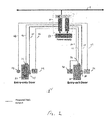
- FIG. 1 is a schematic diagram illustrating an exemplary access control system 1 employing an embodiment of the present invention.
- An access control system may include, for example, one, two or more controlled doors, (e.g., doors, turnstiles, gates, vehicle barriers, etc.).
- the system shown in FIG. 1 has two doors 20, 30.
- Door 20 is an entry-only door (i.e., requiring authorization before permitting entry) and is associated with card reader 22 such as a Wiegand reader, powered door lock 24, door sensor 26 and exit sensor 28.
- the second door 30 in this example is an entry-exit door 30, and may be associated with two card readers (an entry reader 32 located outside the restricted area and an exit reader 38 located inside the restricted area).
- an access control system may comprise any number of doors in various combinations of entry-only, exit-only and combined entry-exit doors and that the system of FIG. 1 is simply for illustrative purposes.
- the control panel 10 may comprise a general controller module (GCM) 6 and two access control modules (ACMs) 8.
- the ACMs are controlled by the GCM 6 and each ACM 8 controls one of the doors 20, 30.
- the GCM may comprise a processor running an operating system, with memory, and network and communication ports.
- the GCM also supports one or more ACMs. It would be understand that the GCM and ACMs do not need to be physically separate devices.
- the GCM may communicate with other external systems and/or monitoring services over a network 2.
- a power supply 60 provides power to the control panel 10.
- the control panel 10 provides power to and communicates with the doors (i.e., locks, readers and other associated sensors) through various cabling.
- card reader 22 communicates with control panel 10 via cable 46; door lock 24 is powered via cable 44; and sensors 26 and 28 communicate with control panel 10 via cables 42 and 40 respectively.
- card readers 26 and 38 communicate with control panel 10 via cables 56 and 50 respectively; door lock 34 is powered via cable 54; and sensor 36 communicates with control panel 10 via cable 52.
- FIG. 2 is a schematic diagram further detailing portions of the access control system of FIG. 1 .
- Input power is provided at input power port 62.
- Input power may be, for example, nominally 120 volts AC at 60 Hz or some other standard or non-standard power.
- the power supply 60 may convert the input power into three distinct output power ports, providing 12 volts at output 1 (70) to power the panel 10 circuits, for example the GCM 6 and ACMs 8, as well as the readers 82 (corresponding to readers 22, 32, 38 of FIG. 1 ).
- a second 12-volt output power port 72 provides power for locks operating at 12 volts.
- a third output power port 74 provides 24 volts for power locks that require 24 volts for operation. Each of these outputs may have very different power draw requirements. Further, upon failure of any one of the three power outputs (due to internal failure or a short circuit, for example), the non-failing outputs are capable of continuing to provide power to maintain the locks or circuits.
- the power supply 60 and the control panel 10 are each independently capable of communicating over network 2.
- a backup battery bank 66 comprises one or more backup batteries. Here two 12-volt batteries are connected in series to provide 24 volts. This single 24-volt backup supply provides backup for all three output ports, i.e., both the 24-volt and 12-volt output ports, as described later.
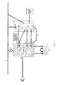
- FIG. 3 is a schematic diagram of a power supply 60 as employed in the system of FIGS. 1 and 2 .
- the power supply 60 receives input or line power at 62, and includes a line filter and fusing 130, a charging circuit 132 for charging the backup batteries 66, an equipment power block 61 for converting input power to the desired output voltages and providing power to the control panel.
- the power supply may also include a monitor and control section 140 to monitor and control aspects of the power supply.
- the battery pack 66 is shown separately but could be integrated with the power supply 60.
- a power factor correction (PFC) unit 102 stores energy at a high DC voltage such that the current drawn by the supply is nearly constant.
- the PFC 102 can shut down all access control outputs during an overcurrent event.
- the PFC output 109 is fed to a Supply Power Limit Voltage Regulation circuit 104 which feeds a high-frequency (for example. ⁇ 100kHz) power 150 to transformer 106.
- a high-frequency (for example. ⁇ 100kHz) power 150 to transformer 106.
- Separate 24VAC and 12VAC outputs are rectified by rectifier/filters 108 and 110 respectively.
- the rectified 24 VDC output 156 is one of two power inputs to switch 112.
- the other input to switch 112 is the battery backup supply 160. Normally, if commercial power 62 is available and the PFC 102 is operating correctly, the switch will pass the rectified 24 VDC 156 to a 24V current limiting circuit 120.
- a signal 105 may be provided to indicate whether the PFC is operating or not.
- the current limiting circuit 120 holds a set point in nonvolatile storage (alternatively, the set point may be held externally and communicated to the current limiting circuit).
- a microcontroller in block 140 may have a non-volatile digital potentiometer to set and hold the current limit. This non-volatile digital potentiometer can maintain current settings until reprogrammed by the microcontroller.
- the power supply circuitry also includes an output current limiting circuit (120, 124, 126) that delivers a programmable maximum current.
- the circuit controls overcurrent by disconnecting the terminal (output) voltage supplied to the load device after approximately one second.
- a timer may be started wherein the output is immediately disconnected if the overcurrent is above a programmable limit. In part, this is to accommodate loads (e.g., door locks) that are primarily resistive with an inductive surge.
- loads e.g., door locks
- a time limit is preferably placed on this process, because generally if a lock takes a long to move, that is more likely due to a genuine fault, and could cause the current limiting circuit to fail.
- Terminal voltage may also be monitored so that if the terminal voltage drops below a threshold the event is recorded.
- the power supply may also inform the control panel 10 of an overcurrent event to help prevent damage to the controlling equipment from such an event, such that the offending device(s) may be selectively disconnected.
- FIG. 4 is a schematic diagram of a monitoring and switching circuit (or current limiting circuit) 420 as employed in an embodiment of the invention.
- the monitoring and switching circuit may 420 correspond with any of current limiting circuits 120, 124 or 126 of FIG. 3 , and may include a current-to-voltage amplifier 410 with an input resistor (not shown) to measure output current.
- the current draw can be measured/monitored using an analog-to-digital converter (ADC).
- a comparator 400 compares the current draw indication (or converted voltage) 403 with a set point 401, and the comparator output 405 drives a delay circuit (for example, an RC delay circuit) 407 to delay a hardware shutdown when the output current exceeds the set point.
- a delay circuit for example, an RC delay circuit
- the time delay may be, for example, one second, such that transient events (of a relatively short interval) do not cause latching of the output in the off state. If the set point is still exceeded beyond the delay period, the output is turned off and held off by a latch 417.
- the comparator output may signal the overcurrent event to the microcontroller.
- rectifier/filter 110 provides two 12VDC outputs 158, 159, that are fed respectively to switches 114 and 116.
- Switches 114 and 116 behave in similar fashion to switch 112 discussed above, with the exception that the second input to each switch is a 12 VDC output 162 from battery voltage conversion circuit 118, which converts the battery backup voltage 160 from 24VDC to 12VDC.
- the output of switch 114 feeds a 12 V current limit circuit 124 and switch 116 feeds 12V current limit circuit 126.
- the current limit circuits 124, 126 behave similarly to the 24V current limit circuit 120 described previously.
- Current limit circuit 124 provides power to 12V locks while current limit circuit 126 provides power to the panel (and other equipment). Because of the different requirements of the locks and panels, and because it is desirable for the locks to continue to operate in the event of a panel failure and vice versa, each current limiting circuit 124, 126 has its own set point, and the circuits operate independently of each other.
- the current limit circuits 120, 124, 126 provide indication signals such as representative signals 122, 128 to the microcontroller to indicate whether power is on or off, or whether a limit has been set, for the respective power outputs 74, 72, 70.
- a charging circuit 132 which may or may not be a separate unit from the power supply 60, provides battery charge power 134 to the backup battery 66.
- the monitor and control unit 140 may set the charge current via a non-volatile digital potentiometer (not shown).
- the charge current may be monitored.
- the monitor and control unit may measure the charge current with an ADC, and cycle the circuit on and off when the charge current exceeds the set point.
- An output flag (not shown) may indicate overcurrent.
- the backup battery voltage may be monitored. For example, to derive battery life the monitor and control unit may measure the battery voltage under load when input AC power 62 is absent to prevent deep discharge or to determine whether the battery is present.
- a DC-DC converter 138 derives power from line power (stepped down) or from the backup battery to supply the appropriate power for the monitor and control unit 140.
- the Monitor and Control unit (MCU) 140 provides several functions, such as RS-232, RS-485 and Ethernet interfaces, a microcontroller, and various I/O control and monitor signals 105, 122, 128, etc. to the power supply 60.
- Secure (authenticated and encrypted) communications may be provided for monitoring and control of the power supply as part of an integrated access control solution.
- the power supply MCU 140 may monitor and control the charging current to account for different battery capacities and technologies. For example, while the power supply is online and connected to a central database, new and different charging profiles can be loaded into the power supply. Thus, a larger battery pack can be charged either more slowly, or if the aim is to provide less current over a longer time, the parameters can be adjusted accordingly. Further, batteries from different manufacturers may have differing charging profiles. As well, batteries with differing chemistries such as Lithium-ion may be charged by the same controller, without a technician having to visit the site to make changes.
- the power supply may also monitor and control the power supply current limits for the multiple output voltages, as well as AC power loss and battery-backed operation.
- the power supply includes a multi-chemistry battery charge current limiting circuit 142 that provides efficient charging of batteries having various chemistries.
- the power supply monitors the current drawn, and by use of a controllable constant current source, can limit the current drawn by the battery. While this may change the time to charge the battery, the charge current can be adaptive to match the load drawn on the outputs. This ensures that the maximum rated output current of the power supply is maintained irrespective of the charge state of the batteries.
- the battery charge current limiting circuit 142 may deliver a programmable maximum charge current in the initial phase of battery charging: monitors the battery voltage to determine the charge state of the battery; and based upon the battery voltage, reduce the charge current as the battery reaches the "topping off" and "float” stages.
- the power supply further allows the control panel to retry and otherwise manage an overcurrent event.
- retry algorithms can automatically restore and maintain system operation.
- output prioritization can be employed where lower priority devices are shut down to maintain operation of high priority devices.
- locks can be prioritized such that those with lower priority are disconnected by installing lower priority locks on a different output than those with higher priority. For example, it may be preferable to drop access control to a computer room last, but allow free access on turnstiles.
- An embodiment of the multi-output supply can simultaneously operate and monitor both 12V and 24V devices, and dynamically allocate power to these devices.
- the power supply uses an active circuit to switch to a battery-generated supply.
- the power supply informs the system power has been lost, by sending an alarm signal, for example, to the GCM and/or the central monitoring station.
- the power supply further monitors the battery to prevent deep discharge.
- the processor may also monitor the status of the power supply inputs and outputs and reporting of events, as well as a limited amount of other control functionality, such as turning on or off individual power outputs and setting maximum current limits on the power outputs.
- the power supply may be monitored and configured through a simple menu-based system via, for example, an RS-232, USB or other serial "debug" port (shown within the monitor and control unit 140). Reports of events, alarms and warnings may be sent from the debug port as they occur. A listing of logged events 170 may be maintained and made accessible via the debug port. Firmware download through the debug port may be supported through a simple file transfer protocol such as Kermit or XModem. The debug port may also provide basic development and field debug capability.
- the power supply may also communicate directly with a host such as a CCURE 9000 workstation or a remote web client, or the power supply may communicate with the access control panel 10 via an RS-485 connection/protocol, and the panel in turn may report the power supply status and alarms to the host.
- a host such as a CCURE 9000 workstation or a remote web client
- the power supply may communicate with the access control panel 10 via an RS-485 connection/protocol, and the panel in turn may report the power supply status and alarms to the host.
- the power supply may communicate with the control panel via Ethernet on a private network, or to a PC or other computing device via a webserver provided on the power supply.
- a secure webserver may be implemented that allows the setting of system parameters and monitoring system states via a remote web browser.
- the processor may be a microcontroller with an ARM core. Instructions (firmware code) for running the processor may reside entirely in FLASH memory within the microcontroller.
- the microcontroller may have FLASH memory for storage of code, parameters, backup, etc.
- the firmware may be upgradeable in the field.
- the firmware RAM including stacks, local and global variables, and databases (if present) may reside entirely or partially within, or completely outside, the microcontroller.
- the microcontroller may access an external mass storage memory chip (EEPROM, FLASH, etc.) via a standard serial protocol (SPI, I2C, etc.), for potential future storage of large data files, such as web pages, etc.
- Tri-color LEDs on the power supply front panel may provide indications. For example: overall system status; status for each of the three power outputs; battery charger status; RS-485 port status; and Ethernet port status.
- amber can be achieved by activating red and green simultaneously, or by activating them alternately.
- a System Status LED shines RED to indicate a System Fault such as when PFC Overcurrent Shutdown is active or Total Power Exceeds Maximum Limit is active.
- YELLOW indicates the system is running on batteries; that is, AC presence is not detected or the Battery Test Active is active.
- GREEN indicates that conditions are normal.
- Output Status LEDs may be provided for each power output. RED indicates that the corresponding power output has been shut down. YELLOW indicates that the output is trying to be re-established. GREEN indicates that the output is active, i.e., delivering or capable of delivering power.
- An RS-485 Status LED shines GREEN to indicate that the RS-485 port is communicating with a host or with the panel.
- YELLOW indicates that the RS-485 port is acquiring a link.
- RED indicates that the RS-485 port is offline.
- an Ethernet Status LED shines GREEN to indicate that the Ethernet port is online.
- YELLOW indicates that the Ethernet port is acquiring a network address.
- RED indicates that the Ethernet port is offline.
- a Battery Charger Status LED may shine GREEN to indicate that the battery is fully charged and in float stage.
- YELLOW indicates that the battery is charging in topping stage.
- YELLOW Flashing indicates that the battery is charging and is in the boost stage.
- RED indicates a battery/charger fault.
- OFF indicates that there is no battery.
- An Enclosure Status indicator light may be provided to indicate whether the unit is powered while the enclosure door is closed without light pipes or other methods that would increase costs. For example, a superbright LED may be utilized, which output is optically attenuated by a window in the enclosure door.
- the Enclosure Status LED may electronically dim when the enclosure door has been opened (detected by a tamper switch), so as not to be blinding. If this LED is OFF, attention is required.
- FLASHING indicates a problem or fault, for example a Power Factor Correction Overcurrent Shutdown is active or Total Power has exceeded the Maximum Limit. ON indicates that the status is good.
- Two controls can be used to activate this LED through two different load resistors, so that three brightness levels (plus off) can be attained.
- An internal timer may be used to flash any of the LEDs, for example at a rate of 2 Hz.
- an AC Power Present signal 105 indicates whether AC power is present on the power input. Additionally, the output of the circuitry that limits Power Output current will be monitored, to determine if the circuitry is actively limiting the current (122,128, "Flag").
- Each of the power output currents may be monitored by an analog-to-digital (A/D) converter connected to the Output Power Current Measurement circuitry.
- a simple infinite impulse response (IIR) filter may be used to smooth the measured value. Because the Power Output current limiting circuit acts to limit current by switching the Power Output on and off, when the Power Output Current Limit Active input is Active, a longer finite impulse response (FIR) filter may be applied to the power output current measurements.
- IIR infinite impulse response
- Each of the output power voltages may be monitored by an A/D converter connected to the Output Power Voltage Measurement circuitry.
- a simple IIR filter may be used to smooth the measured value. Because the Power Output current limiting circuit acts to limit current by switching the Power Output on and off, when the Power Output Current Limit Active input is Active, a longer FIR filter may be applied to the output power voltage measurements.
- the current limit for each Power Output may be set by writing binary values to the power output current limiting circuit. Writing a '0' value may disable the Power Output.
- the interface may comprise digital potentiometers connected to the processor serial peripheral interface (SPI) port.
- the output of the Power Factor Correction circuit can be disconnected from all internal and external circuitry by a switch circuit, under control of the microcontroller. By default, this switch will normally be turned ON upon processor reset.
- the output of the circuitry that limits Battery Charger Current may be monitored by the microcontroller to determine if the circuitry is actively limiting current.
- the Battery Charging Current input may be monitored by an A/D input connected to the Battery Charge Current Measurement circuitry.
- a filter such as a simple IIR. filter, may be used to smooth the measured value. Because the Battery Charger current limiting circuit acts to limit current by switching the Battery Charger on and off, when the Battery Charger Current Limit Active input is Active, a longer FIR filter may be applied to the Battery Charger Current measurements.
- the Battery Terminal Voltage may be monitored by an A/D input connected to the Battery Terminal Voltage Measurement circuitry. Because the Battery Charger current limiting circuit acts to limit current by switching the Battery Charger on and off, when the Battery Charger Current Limit Active input is Active, a longer FIR filter may be applied to the Battery Terminal Voltage measurements.
- the current limit for the Battery Charger may be set by writing binary values to the battery charger current limiting circuit. Writing a '0' value may disable the Battery Charger.
- the interface may comprise digital potentiometers connected to the processor SPI port.
- At least one embodiment may include two front panel pushbutton switches, RESET and Shutdown, recessed to prevent accidental activation. Pressing only RESET may reset the microprocessor and existing programmable settings while any event logs and related items may be maintained. Pressing Shutdown for, say, approximately two seconds may disconnect the battery charger output. This facilitates battery replacement. Feedback may be provided to the user via the front panel LEDs. After battery replacement, pressing the shutdown switch for some length of time, for example two seconds, will reconnect the battery. Pressing Shutdown for a different length of time, for example approximately five seconds, may set all output current limits to zero thus shutting down the outputs. The user is provided feedback via the front panel LEDs, i.e. they wait until all outputs are shown as "off”. To recover from this situation the power to the unit can be cycled or press RESET for 5 seconds (see 5.1.2).
- An event log 170 may be maintained by the power supply for inspection by a user or administrator or for later analysis. Analysis of the log information (i.e. , overcurrent, voltage out of spec, AC power lost/restored, etc.) can be used manually (or automatically according to some algorithm) to tune the power supply, i.e., set the operating parameters to match observed conditions, or reallocate power.
- Analysis of the log information i.e. , overcurrent, voltage out of spec, AC power lost/restored, etc.
- tune the power supply i.e., set the operating parameters to match observed conditions, or reallocate power.
- the event log may be maintained in external non-volatile memory, such as EEPROM or NAND FLASH.
- Events can be stored in a transactioned format, and each record will contain at a minimum: A record number, an identifier of the logged state, the state value, and the RTC time of the event, and a checksum for the event record.
- Events may be stored in ring buffer format so that after the buffer is full the newest event records will over-write the oldest event records. Start and End buffer tokens can be updated each time an event record is added so that proper sequencing of the Event Log may be maintained, even after a processor reset.
- an Event is recorded after its initial occurrence, and then a running count of reports of the same Event is maintained. The Event will only re-record after a programmable number of additional occurrences or if the Event recurs after a programmable amount of time. Exemplary default settings are 10 occurrences and 10 seconds.
- a Power Output servicing function monitors the power outputs reporting the operating states and events of the power outputs.
- the Power Output Servicing function monitors the current, voltage and power for each power output and may generate event notifications and actions in response to certain conditions.
- the current of each power output is measured and used to compute the power output Average Current and Peak Current for each output are also tracked.
- each power output is checked to see if it is within tolerance (+/-10% of nominal). If the voltage is more than +/-20% out of tolerance, the Power Output Voltage status is determined to be Out of Tolerance and an alarm condition is set. If the voltage is more than +/-10% out of tolerance (but less than +/-20%), a Power Output Voltage is determined to be Out of Tolerance and a Warning condition is set. Finally, if the voltage is within tolerance, a Power Output Voltage is determined to be normal.
- Total Power for each output is calculated by multiplying voltage by current.
- Total Power of all outputs is calculated by summing the calculated power of all of the outputs. If Total Power exceeds some threshold, such as 180 watts, a Total Power Output Voltage Out of Tolerance alarm condition is set. If the Total Power exceeds a second threshold, such as 160 watts, but is under the first threshold, a warning condition may be set. If Total Power is below this second threshold, a normal condition is set.
- Power Output Current Limit Active represents the state of Power Output Current Limit circuit. When active, the circuit has been disconnected due to an over-current event.
- the Power Output Current Limit value for each power output may be stored in non-volatile memory. At startup or in response to a protocol command, the Power Output Current Limit may be written to the current limiting hardware.
- Power outputs may be enabled or disabled individually, either in direct response to a command, in response to activation of a SHUTDOWN panel button, or by an algorithm for timed re-tries for re-enabling power outputs.
- the access control panel may send commands to the unit to set parameters for the automatic power re-enabling.
- the parameters controlling the power output shutdown/retry algorithm are as follows. Default values are provided for illustrative purposes.
- Output Shutdown Time (sec): The time that the output will be shutdown before trying to turn it back on. Default: 10 sec.
- Output Shutdown Offline Time After the maximum number of retries has been exceeded, the length of time that the output will remain shut down before attempting to begin retries. Default 10 minutes.
- FIG. 6 is a flowchart 600 of a power output control function.
- a power output's current exceeds some predetermined threshold (Power Output Current Limit Active is active) for more than some corresponding time limit (Output Over Current Time) as determined in step 601, i.e., a sustained over-current condition has occurred, then within the Overcurrent and Retry parameters previously discussed the output is switched off and an Output Retry counter is incremented (step 603).
- step 605 After the Output Shutdown Time (step 605), the Output Over Current Time timer is reset and the Power Output is turned back on (step 607). If the Power Output Current Limit remains Active for the Output Over Current Time (determined at step 613), the sequence repeats, until the Output Shutdown Maximum Retries is reached. Once the Output Shutdown Maximum Retries is reached (determined at step 609), the output remains shut down and the Output Shutdown Offline Time timer is started (step 611).
- the Output Retry counter is reset (step 617).
- FIG. 7 is a flowchart 700 of a power output shutdown/retry function according to an embodiment of the present invention.
- the Power Output Shutdown/Retry function shown in FIG. 7 will be applied if the total power exceeds some maximum power, for example 160 watts.
- some maximum power for example 160 watts.
- the power supply will preemptively shutdown one of the power outputs (step 703). If this does not reduce the power below the limit (determined at step 705), a second Power Output will be shutdown (step 707).
- the order in which the outputs are shut down may be configured by the user. The same shutdown time/retry parameters can apply to shutting down outputs due to exceeding maximum power.
- the current limits may be set to default values on reset of the power supply.
- the default current limits allow any output to supply the entire 160 W available.
- the current limits may be modified by means of the menu-based interface on the debug port. Outputs may be disabled/re-enabled via automatic control in response to the detection of overcurrent events, or via a physical SHUTDOWN pushbutton.
- the shutdown time/retry parameters and output priorities may also be modified by the menu based interface. Average and Peak Current values may be accessible via the menu.
- individual outputs can be disabled/re-enabled by protocol command input, as will the other Power Output control parameters and measurements. Reporting of events and alarms may also be available via the communications protocol.
- Fig. 8 is a graph which further illustrates monitoring of a power output.
- a representative power output current over time is designated by line 802.
- a threshold current level has been set at 801.
- the output current exceeds threshold 801 for 3 seconds. If the Power Over Current Time is set to, for example, 2.5 seconds, this output will be shut down (not shown).
- a Battery Charging and Management servicing function 132 monitors various inputs and generates actions. Inputs include the battery charging current, battery terminal voltage, ambient temperature, and battery detection. For example, lead-acid batteries should not be charged below freezing or above 50°C. In addition, the charging profile may be controlled by ambient temperature. Batteries with other chemistries will have different requirements.
- the battery terminal voltage may be measured 1) when the battery charger is enabled, in order to determine battery charge state; and 2) when the battery charger is disabled, in order to detect the presence of the battery.
- an alarm message may be generated and/or logged.
- a warning may be generated and/or logged.
- the battery charger 132 Periodically, and while AC is detected, the battery charger 132 will be disabled and the battery terminal voltage measured. If the voltage is below a threshold such as 8 volts, the battery may be considered to be absent.
- FIG. 5 is a flowchart 500 of a battery charge scheme according to an embodiment of the present invention.
- step 501 If the battery has been determined to be absent (step 501), the battery charger is disabled.
- the battery charge current is adjusted for ambient temperature, for example, in the temperature range of - 15 ° C to 50°C.
- the battery is not charged outside of this temperature range.
- the battery charging algorithm may include several parameters which may be set by the user. If no parameters are set by the user, default values are used.
- the charging parameters include (all given default values are for illustrative purposes only):
- Boost Stage Maximum Time Maximum time allowed for charging at the Boost Stage. Default: 16 hours.
- Threshold Current Threshold of charging current below which the battery charger will end the Topping Stage and enter the Float Stage. Default: 0.5 Amp.
- the stages for charging the battery after A/C power restore or battery replacement are 1) Boost Stage; 2) Topping Stage; and 3) Float Stage.
- Battery charging begins with the boost stage 503.
- the battery charger current limit is set to the Boost Stage Charge Current, and the Boost Stage Charge Timer is reset.
- the boost stage ends when, as determined at step 505 either 1) the Battery Charging Current drops below a threshold and/or the terminal voltage rises above a threshold indicating the battery can enter the Topping Stage; or 2) the battery charging current exceeds a current limit threshold after a Boost Stage Maximum duration has elapsed.
- the battery charger When the battery charging current does not exceed the current limit threshold, the battery charger then enters the Float Stage (step 507).
- the Battery Charging Current Limit Active remains active after the Boost Stage Maximum Time has elapsed, the battery charger is disabled (step 517). Battery charging will not resume until a Processor Reset, a Battery Disconnect/Reconnect, or Factory Default Reset is initiated.
- the charge current may be periodically set to zero (the battery is disconnected from the charger) while the terminal voltage is measured After the Terminal voltage is measured the Float Stage current setting is restored. If the battery self-discharges below a threshold (Step 509), the algorithm progresses to the Topping Off State (Step 511).
- the Float Stage may continue indefinitely, until either AC Power Present goes from Inactive to Active (AC power is lost), a Processor Reset, a Battery Disconnect/Reconnect, or a Factory Default Reset, any of which are determined at step 513. While AC power is lost the battery supplies power to the access control equipment and all charging is inactive. Following a Battery Disconnect all charging is inactive. Following Processor Reset, Battery Reconnect, and a Factory Default Reset charging resumes from the Boost Stage.
- the battery terminal voltage (with charger momentarily turned off) is detected to be above 13.2 V, the battery is determined to be in normal condition.
- Switch-over to battery after AC power fails is performed automatically by hardware. However, firmware is able to detect this occurrence by monitoring the AC Present circuitry.
- a timer is started so that battery run-time running may be reported.
- the Battery Charger is disabled when the system is powered by battery.
- the battery terminal voltage is monitored, and if the battery voltage is below 10.8 V, the battery is determined to be low.
- the battery current is cut off (turning off all internal and external power) to prevent deep-discharge of the battery.
- a Battery Test Schedule feature may be provided to allow a user to schedule regular testing of the battery backup system by disconnecting the AC input and allowing the power supply to operate off from the batteries.
- the Battery Test Schedule feature may be available only when a real-time clock (not shown) has been set.
- the Battery Test Schedule operates with the following parameters: Battery Test Enable; Battery Test Frequency; Battery Test Time; Battery Test Day; and Battery Test Length. Default values are provided for illustrative purposes.
- Battery Test Enable The Battery Load Test Schedule feature is enable when this is set to True. Default: False.
- Battery Test Frequency The frequency at which the Battery Test will be scheduled. May be set, for example, to Daily, Weekly, or Monthly. Default: Weekly.
- Battery Test Day The day that the Battery Test is scheduled to occur. If Battery Test Frequency is set to Weekly, the day may be set to any of the days of the week If the frequency is set to Monthly, Battery Test Day may be set to day of month. To address the issue of months having different numbers of days, the day on month may, for example, be limited to values in the range of 1-28. Default: Sunday.
- Battery Test Length Length of time to perform Battery Test. Default: 10 min.
- the Battery Test will be performed at the time and day scheduled, but only if the battery test is enabled, A/C is detected, and a battery is present.
- Battery Test is performed by setting the AC Power Disable output to Active.
- the Battery Test timer is reset.
- a Battery Test Active change of state to Active message is sent to the Event Processor.
- the AC Power Disable output is set to Inactive, and a Battery Test Active change of state to Inactive message is sent to the Event Processor.
- a Battery Service Life parameter defines the service life of the battery before it must be replaced.
- An exemplary default value is 2 years.
- a user can mark the time and date a battery has been replaced. The time that the battery has been in service is measured with the Real Time Clock from the time/date of battery replacement.
- the battery should be serviced a set time after installation. To this end, a service timer is maintained. This set time (Battery Service Time) can change due to the performance of the battery on the previous charge cycle.
- the Battery Service Time and a Battery Service Warning may be available via the debug port.
- a user may be allowed to mark the time/date of battery replacement through a host (such as CCURE) to the Control Panel, and the Control Panel may relay this action to the power supply, for example, via an RS-485 protocol command. After the Battery Service Life has transpired, the power supply may send a warning message to the Panel, and this message will be relayed by the Control Panel to the host.
- control panel must periodically update the current time and date in the power supply to correct for drift in the pseudo-RTC, and also to restore the time date in the pseudo-RTC in case ofpower failure.
- Other ways of synchronizing the pseudo-RTC may also be available.
- the processor supports an orderly shutdown, including sequential disabling of battery charging and power outputs. This feature can be initiated either by a switch or a command.
- the switch input may involve an interlock, in which case several inputs states may need to be monitored.
- a SHUTDOWN button may allow access to the shutdown features, such as: Processor Reset; Battery Disconnect; Output Disconnect; and Factory Default Reset.
- Processor Reset requires settings to be maintained when the processor is reset. After a reset, the processor explicitly sets the current limiting hardware to their previously set values, in a manner that prevents an interruption to the output current (if hardware allows).
- the processor may store event logs in a non-volatile memory to ensure that the logs are maintained through a reset.
- the event log may be stored in a first-in first-out format, and may be transactioned to ensure that entire records are integral.
- the Battery Disconnect function monitors the SHUTDOWN button.
- the processor toggles the battery charger on or off (depending on the prior state).
- the button must be released and repressed to toggle the battery charger back to its original state.
- a message with the new Battery Charger State will be sent to the Event processor with a priority of Normal. Note that if all power outputs have been turned off, then the battery charger will also be turned off, and cannot be turned back on by pressing the Shutdown button.
- the power supply will perform as normal from a hard reset.
- the outputs will be shut down for, say, one second and the corresponding LEDs will be turned off. After another interval, for example one second, the outputs will be re-enabled (with their factory default values), and the LEDs will be re-lit to reflect the state of the outputs.
Landscapes
- Engineering & Computer Science (AREA)
- Power Engineering (AREA)
- Physics & Mathematics (AREA)
- Electromagnetism (AREA)
- General Physics & Mathematics (AREA)
- Radar, Positioning & Navigation (AREA)
- Automation & Control Theory (AREA)
- Business, Economics & Management (AREA)
- Emergency Management (AREA)
- Charge And Discharge Circuits For Batteries Or The Like (AREA)
- Direct Current Feeding And Distribution (AREA)
Applications Claiming Priority (1)
| Application Number | Priority Date | Filing Date | Title |
|---|---|---|---|
| US13/715,389 US9397520B2 (en) | 2012-12-14 | 2012-12-14 | Intelligent adaptive power supply |
Publications (3)
| Publication Number | Publication Date |
|---|---|
| EP2743792A2 true EP2743792A2 (de) | 2014-06-18 |
| EP2743792A3 EP2743792A3 (de) | 2015-01-07 |
| EP2743792B1 EP2743792B1 (de) | 2023-09-13 |
Family
ID=49882800
Family Applications (1)
| Application Number | Title | Priority Date | Filing Date |
|---|---|---|---|
| EP13197007.1A Active EP2743792B1 (de) | 2012-12-14 | 2013-12-12 | Intelligente adaptive Leistungsversorgung |
Country Status (2)
| Country | Link |
|---|---|
| US (1) | US9397520B2 (de) |
| EP (1) | EP2743792B1 (de) |
Cited By (3)
| Publication number | Priority date | Publication date | Assignee | Title |
|---|---|---|---|---|
| CN110750378A (zh) * | 2019-09-30 | 2020-02-04 | 山东信通电子股份有限公司 | 一种多电源下电时序电路和下电方法 |
| EP3604046A4 (de) * | 2017-03-27 | 2020-04-15 | Panasonic Intellectual Property Management Co., Ltd. | Fahrzeuginterne stromversorgungsvorrichtung und fahrzeug mit darin montierter fahrzeuginterner stromversorgungsvorrichtung |
| EP3948451B1 (de) | 2019-03-27 | 2024-12-11 | Wago Verwaltungsgesellschaft mbH | Elektronikgerät und kommunikationseinheit |
Families Citing this family (18)
| Publication number | Priority date | Publication date | Assignee | Title |
|---|---|---|---|---|
| US10475024B1 (en) | 2012-10-15 | 2019-11-12 | Square, Inc. | Secure smart card transactions |
| US9397520B2 (en) * | 2012-12-14 | 2016-07-19 | Sensormatic Electronics, LLC | Intelligent adaptive power supply |
| EP3011849B1 (de) * | 2013-06-17 | 2018-04-11 | Huizhou Kimree Technology Co., Ltd. Shenzhen Branch | Elektronische zigarette und verfahren zur steuerung der lichtemission einer elektronischen zigarette |
| US20150155736A1 (en) * | 2013-11-30 | 2015-06-04 | Ying Sun | Method and Apparatus for Extending Service Life of a Battery Source |
| US9419445B2 (en) * | 2014-01-30 | 2016-08-16 | Tejas Networks Ltd | Method and system for extending battery power at cell sites |
| US9760740B1 (en) | 2014-06-23 | 2017-09-12 | Square, Inc. | Terminal case with integrated dual reader stack |
| WO2015200437A1 (en) * | 2014-06-25 | 2015-12-30 | Emerson Network Power, Energy Systems, North America, Inc. | Battery backup units and systems including bypassing circuitry for regulating outputs |
| US9870491B1 (en) * | 2014-08-01 | 2018-01-16 | Square, Inc. | Multiple battery management |
| US10753982B2 (en) | 2014-12-09 | 2020-08-25 | Square, Inc. | Monitoring battery health of a battery used in a device |
| US20170126057A1 (en) * | 2015-11-02 | 2017-05-04 | Champion Engine Technology, LLC | Generator having improved cold weather starting |
| US10230261B2 (en) * | 2015-11-18 | 2019-03-12 | Eaton Intelligent Power Limited | Power control circuits and related uninterruptible power supply systems |
| US10472807B2 (en) * | 2016-06-02 | 2019-11-12 | Merdick Earl MCFARLANE | Prevention of freezing of outdoor water line |
| MX2019014364A (es) * | 2017-05-30 | 2020-02-05 | Hubbell Inc | Conector de alimentación con monitoreo de estado integrado. |
| US10559962B2 (en) * | 2018-01-06 | 2020-02-11 | Aic Inc. | Power-outputting management method for power-supplying apparatus |
| US12345226B2 (en) | 2019-04-19 | 2025-07-01 | Champion Power Equipment, Inc. | Electronic ignition system for a generator engine |
| US11057727B2 (en) * | 2019-10-18 | 2021-07-06 | Cirrus Logic, Inc. | Dynamic power/current allocation among groups of audio amplifiers and/or haptic drivers |
| US11545851B2 (en) | 2020-08-10 | 2023-01-03 | Saudi Arabian Oil Company | Systems, methods, and apparatuses for distributing backup electrical power |
| US12456362B2 (en) * | 2022-10-14 | 2025-10-28 | Tyco Fire & Security Gmbh | Communications bridge with unified building alarm processing |
Family Cites Families (24)
| Publication number | Priority date | Publication date | Assignee | Title |
|---|---|---|---|---|
| US2275882A (en) * | 1939-10-31 | 1942-03-10 | Gen Electric | Control system |
| JP2000322133A (ja) | 1999-05-07 | 2000-11-24 | Canon Inc | スイッチング電源回路 |
| US6791853B2 (en) * | 2001-12-03 | 2004-09-14 | Mobility Electronics, Inc. | Dual input AC/DC power converter having a programmable peripheral power hub module |
| US7444207B2 (en) * | 2002-10-15 | 2008-10-28 | Rain Bird Corporation | Modular and expandable irrigation controller |
| TW200413896A (en) | 2003-01-24 | 2004-08-01 | Mitac Technology Corp | Power management and control method of power supply and device thereof |
| US6912123B2 (en) * | 2003-09-09 | 2005-06-28 | Nipron Co., Ltd. | Power supply device |
| JP4439443B2 (ja) * | 2005-07-08 | 2010-03-24 | 富士通株式会社 | 直流電圧変換機能を含む電子機器、および直流電圧変換回路 |
| US7630841B2 (en) * | 2007-03-30 | 2009-12-08 | Texas Instruments Incorporated | Supervising and sequencing commonly driven power supplies with digital information |
| US8390965B2 (en) * | 2008-05-07 | 2013-03-05 | Cal-Comp Electronics & Communications Company Limited | Over-current protection device for multiple high-voltage motive devices and method thereof |
| JP4591571B2 (ja) * | 2008-08-04 | 2010-12-01 | 株式会社デンソー | 電源装置 |
| US7948114B2 (en) * | 2008-11-26 | 2011-05-24 | Stmicroelectronics Asia Pacific Pte. Ltd. | Apparatus and method for providing a power switch array with adjustable current rating power switches |
| JP5251455B2 (ja) | 2008-11-27 | 2013-07-31 | 富士通セミコンダクター株式会社 | Dc−dcコンバータの制御回路、dc−dcコンバータの制御方法及び電子機器 |
| JP5610585B2 (ja) | 2009-03-13 | 2014-10-22 | ローム株式会社 | 多出力電源装置及びこれを用いた電気機器 |
| EP2330481A1 (de) * | 2009-12-03 | 2011-06-08 | Racktivity NV | Datenzentrenverwaltungseinheit mit verbesserter Katastrophenverhinderung und Wiederherstellung |
| JP5583394B2 (ja) | 2009-12-09 | 2014-09-03 | Fdk株式会社 | サーバーの無停電電源装置 |
| US20110148197A1 (en) | 2009-12-21 | 2011-06-23 | Maurilio Hernandez | In-line uninterruptible power supply |
| US9952565B2 (en) * | 2010-11-15 | 2018-04-24 | Guang Liu | Networked, channelized power distribution, monitor and control for security and life safety applications |
| IL210651A0 (en) * | 2011-01-13 | 2011-03-31 | Haim Jacobi | Substantially concealed smart housing for wall mounted electrical elements |
| CN103503265B (zh) * | 2011-01-31 | 2017-02-15 | 米尔班克制造有限公司 | 能量接口系统 |
| WO2013134304A1 (en) * | 2012-03-06 | 2013-09-12 | Planar Systems, Inc. | Transparent electronic image display apparatus for refrigerated merchandisers and the like |
| US8917513B1 (en) * | 2012-07-30 | 2014-12-23 | Methode Electronics, Inc. | Data center equipment cabinet information center and updateable asset tracking system |
| US8946994B2 (en) * | 2012-09-25 | 2015-02-03 | Lg Display Co., Ltd. | Organic light emitting display device and driving method thereof |
| EP2728439A1 (de) * | 2012-10-31 | 2014-05-07 | Thomson Licensing | Vorrichtung und Verfahren zur Stromverwaltung einer Vielzahl von Peripherieschnittstellen |
| US9397520B2 (en) * | 2012-12-14 | 2016-07-19 | Sensormatic Electronics, LLC | Intelligent adaptive power supply |
-
2012
- 2012-12-14 US US13/715,389 patent/US9397520B2/en active Active
-
2013
- 2013-12-12 EP EP13197007.1A patent/EP2743792B1/de active Active
Non-Patent Citations (1)
| Title |
|---|
| SDC: "Modular Access Control Power Supply", 1 January 2007 (2007-01-01), XP055761421, Retrieved from the Internet <URL:https://sdcsecurity.com/docs/636RF%20Power%20Supply%204%20Web.pdf> [retrieved on 20201218] * |
Cited By (3)
| Publication number | Priority date | Publication date | Assignee | Title |
|---|---|---|---|---|
| EP3604046A4 (de) * | 2017-03-27 | 2020-04-15 | Panasonic Intellectual Property Management Co., Ltd. | Fahrzeuginterne stromversorgungsvorrichtung und fahrzeug mit darin montierter fahrzeuginterner stromversorgungsvorrichtung |
| EP3948451B1 (de) | 2019-03-27 | 2024-12-11 | Wago Verwaltungsgesellschaft mbH | Elektronikgerät und kommunikationseinheit |
| CN110750378A (zh) * | 2019-09-30 | 2020-02-04 | 山东信通电子股份有限公司 | 一种多电源下电时序电路和下电方法 |
Also Published As
| Publication number | Publication date |
|---|---|
| EP2743792B1 (de) | 2023-09-13 |
| US9397520B2 (en) | 2016-07-19 |
| US20140167503A1 (en) | 2014-06-19 |
| EP2743792A3 (de) | 2015-01-07 |
Similar Documents
| Publication | Publication Date | Title |
|---|---|---|
| EP2743792B1 (de) | Intelligente adaptive Leistungsversorgung | |
| US7514815B2 (en) | System and method for allocating power to loads | |
| JP5289616B2 (ja) | 電子モジュール形態の無停電電源装置のための回路および方法 | |
| EP2666229B1 (de) | Unterbrechungsfreie stromversorgungen zur verwendung in einem verteilten netzwerk | |
| JP4998909B1 (ja) | 太陽光発電システム | |
| JP2004119151A (ja) | 照明装置並びに照明システム | |
| AU2012207388A1 (en) | Uninterruptible power supplies for use in a distributed network | |
| JP6018449B2 (ja) | 蓄電池システム | |
| US9893530B2 (en) | Power control device, power control method, and power control system | |
| US20170366029A1 (en) | Power management unit for intelligent traffic system applications | |
| RU2623621C1 (ru) | Система для обмена энергией с электротранспортным средством | |
| JP6091794B2 (ja) | 蓄電池システム | |
| JP2023137159A (ja) | 管理システム | |
| WO2013136655A1 (ja) | 充放電制御装置 | |
| JP6061535B2 (ja) | 蓄電池システム | |
| US9979228B2 (en) | Energy management apparatus and method of controlling the same | |
| CN110445247B (zh) | 高可靠性冗余供电系统及方法 | |
| JP2014027839A (ja) | 蓄電池システム | |
| JP5661531B2 (ja) | 電力供給システム | |
| US12355243B1 (en) | Multiport power management system with battery and connectivity backup capabilities and related methods | |
| CN223230921U (zh) | 一种智能维护高频开关直流电源系统 | |
| EP3365957A1 (de) | Verfahren zur versorgung eines notversorgungsmoduls und notversorgungsmodul mit reduziertem energieverbrauch | |
| JP2016103890A (ja) | 電力制御装置および電力制御システム | |
| JP6018447B2 (ja) | 蓄電池システム | |
| JP6360279B2 (ja) | 蓄電池システム |
Legal Events
| Date | Code | Title | Description |
|---|---|---|---|
| PUAI | Public reference made under article 153(3) epc to a published international application that has entered the european phase |
Free format text: ORIGINAL CODE: 0009012 |
|
| 17P | Request for examination filed |
Effective date: 20131212 |
|
| AK | Designated contracting states |
Kind code of ref document: A2 Designated state(s): AL AT BE BG CH CY CZ DE DK EE ES FI FR GB GR HR HU IE IS IT LI LT LU LV MC MK MT NL NO PL PT RO RS SE SI SK SM TR |
|
| AX | Request for extension of the european patent |
Extension state: BA ME |
|
| RIC1 | Information provided on ipc code assigned before grant |
Ipc: H02J 9/06 20060101ALI20140725BHEP Ipc: G05F 1/00 20060101AFI20140725BHEP Ipc: H02J 3/00 20060101ALI20140725BHEP |
|
| PUAL | Search report despatched |
Free format text: ORIGINAL CODE: 0009013 |
|
| AK | Designated contracting states |
Kind code of ref document: A3 Designated state(s): AL AT BE BG CH CY CZ DE DK EE ES FI FR GB GR HR HU IE IS IT LI LT LU LV MC MK MT NL NO PL PT RO RS SE SI SK SM TR |
|
| AX | Request for extension of the european patent |
Extension state: BA ME |
|
| RIC1 | Information provided on ipc code assigned before grant |
Ipc: G05F 1/00 20060101AFI20141128BHEP Ipc: H02J 9/06 20060101ALI20141128BHEP Ipc: H02J 3/00 20060101ALI20141128BHEP |
|
| R17P | Request for examination filed (corrected) |
Effective date: 20150707 |
|
| RBV | Designated contracting states (corrected) |
Designated state(s): AL AT BE BG CH CY CZ DE DK EE ES FI FR GB GR HR HU IE IS IT LI LT LU LV MC MK MT NL NO PL PT RO RS SE SI SK SM TR |
|
| STAA | Information on the status of an ep patent application or granted ep patent |
Free format text: STATUS: EXAMINATION IS IN PROGRESS |
|
| 17Q | First examination report despatched |
Effective date: 20190227 |
|
| GRAP | Despatch of communication of intention to grant a patent |
Free format text: ORIGINAL CODE: EPIDOSNIGR1 |
|
| STAA | Information on the status of an ep patent application or granted ep patent |
Free format text: STATUS: GRANT OF PATENT IS INTENDED |
|
| INTG | Intention to grant announced |
Effective date: 20230405 |
|
| RAP1 | Party data changed (applicant data changed or rights of an application transferred) |
Owner name: JOHNSON CONTROLS TYCO IP HOLDINGS LLP |
|
| GRAS | Grant fee paid |
Free format text: ORIGINAL CODE: EPIDOSNIGR3 |
|
| GRAA | (expected) grant |
Free format text: ORIGINAL CODE: 0009210 |
|
| STAA | Information on the status of an ep patent application or granted ep patent |
Free format text: STATUS: THE PATENT HAS BEEN GRANTED |
|
| AK | Designated contracting states |
Kind code of ref document: B1 Designated state(s): AL AT BE BG CH CY CZ DE DK EE ES FI FR GB GR HR HU IE IS IT LI LT LU LV MC MK MT NL NO PL PT RO RS SE SI SK SM TR |
|
| REG | Reference to a national code |
Ref country code: GB Ref legal event code: FG4D |
|
| REG | Reference to a national code |
Ref country code: CH Ref legal event code: EP |
|
| REG | Reference to a national code |
Ref country code: DE Ref legal event code: R096 Ref document number: 602013084638 Country of ref document: DE |
|
| REG | Reference to a national code |
Ref country code: IE Ref legal event code: FG4D |
|
| P01 | Opt-out of the competence of the unified patent court (upc) registered |
Effective date: 20231002 |
|
| REG | Reference to a national code |
Ref country code: LT Ref legal event code: MG9D |
|
| REG | Reference to a national code |
Ref country code: NL Ref legal event code: MP Effective date: 20230913 |
|
| PG25 | Lapsed in a contracting state [announced via postgrant information from national office to epo] |
Ref country code: GR Free format text: LAPSE BECAUSE OF FAILURE TO SUBMIT A TRANSLATION OF THE DESCRIPTION OR TO PAY THE FEE WITHIN THE PRESCRIBED TIME-LIMIT Effective date: 20231214 |
|
| PG25 | Lapsed in a contracting state [announced via postgrant information from national office to epo] |
Ref country code: SE Free format text: LAPSE BECAUSE OF FAILURE TO SUBMIT A TRANSLATION OF THE DESCRIPTION OR TO PAY THE FEE WITHIN THE PRESCRIBED TIME-LIMIT Effective date: 20230913 Ref country code: RS Free format text: LAPSE BECAUSE OF FAILURE TO SUBMIT A TRANSLATION OF THE DESCRIPTION OR TO PAY THE FEE WITHIN THE PRESCRIBED TIME-LIMIT Effective date: 20230913 Ref country code: NO Free format text: LAPSE BECAUSE OF FAILURE TO SUBMIT A TRANSLATION OF THE DESCRIPTION OR TO PAY THE FEE WITHIN THE PRESCRIBED TIME-LIMIT Effective date: 20231213 Ref country code: LV Free format text: LAPSE BECAUSE OF FAILURE TO SUBMIT A TRANSLATION OF THE DESCRIPTION OR TO PAY THE FEE WITHIN THE PRESCRIBED TIME-LIMIT Effective date: 20230913 Ref country code: LT Free format text: LAPSE BECAUSE OF FAILURE TO SUBMIT A TRANSLATION OF THE DESCRIPTION OR TO PAY THE FEE WITHIN THE PRESCRIBED TIME-LIMIT Effective date: 20230913 Ref country code: HR Free format text: LAPSE BECAUSE OF FAILURE TO SUBMIT A TRANSLATION OF THE DESCRIPTION OR TO PAY THE FEE WITHIN THE PRESCRIBED TIME-LIMIT Effective date: 20230913 Ref country code: GR Free format text: LAPSE BECAUSE OF FAILURE TO SUBMIT A TRANSLATION OF THE DESCRIPTION OR TO PAY THE FEE WITHIN THE PRESCRIBED TIME-LIMIT Effective date: 20231214 Ref country code: FI Free format text: LAPSE BECAUSE OF FAILURE TO SUBMIT A TRANSLATION OF THE DESCRIPTION OR TO PAY THE FEE WITHIN THE PRESCRIBED TIME-LIMIT Effective date: 20230913 |
|
| REG | Reference to a national code |
Ref country code: AT Ref legal event code: MK05 Ref document number: 1611912 Country of ref document: AT Kind code of ref document: T Effective date: 20230913 |
|
| PG25 | Lapsed in a contracting state [announced via postgrant information from national office to epo] |
Ref country code: NL Free format text: LAPSE BECAUSE OF FAILURE TO SUBMIT A TRANSLATION OF THE DESCRIPTION OR TO PAY THE FEE WITHIN THE PRESCRIBED TIME-LIMIT Effective date: 20230913 |
|
| PG25 | Lapsed in a contracting state [announced via postgrant information from national office to epo] |
Ref country code: IS Free format text: LAPSE BECAUSE OF FAILURE TO SUBMIT A TRANSLATION OF THE DESCRIPTION OR TO PAY THE FEE WITHIN THE PRESCRIBED TIME-LIMIT Effective date: 20240113 |
|
| PG25 | Lapsed in a contracting state [announced via postgrant information from national office to epo] |
Ref country code: AT Free format text: LAPSE BECAUSE OF FAILURE TO SUBMIT A TRANSLATION OF THE DESCRIPTION OR TO PAY THE FEE WITHIN THE PRESCRIBED TIME-LIMIT Effective date: 20230913 |
|
| PG25 | Lapsed in a contracting state [announced via postgrant information from national office to epo] |
Ref country code: ES Free format text: LAPSE BECAUSE OF FAILURE TO SUBMIT A TRANSLATION OF THE DESCRIPTION OR TO PAY THE FEE WITHIN THE PRESCRIBED TIME-LIMIT Effective date: 20230913 |
|
| PG25 | Lapsed in a contracting state [announced via postgrant information from national office to epo] |
Ref country code: SM Free format text: LAPSE BECAUSE OF FAILURE TO SUBMIT A TRANSLATION OF THE DESCRIPTION OR TO PAY THE FEE WITHIN THE PRESCRIBED TIME-LIMIT Effective date: 20230913 Ref country code: RO Free format text: LAPSE BECAUSE OF FAILURE TO SUBMIT A TRANSLATION OF THE DESCRIPTION OR TO PAY THE FEE WITHIN THE PRESCRIBED TIME-LIMIT Effective date: 20230913 Ref country code: IS Free format text: LAPSE BECAUSE OF FAILURE TO SUBMIT A TRANSLATION OF THE DESCRIPTION OR TO PAY THE FEE WITHIN THE PRESCRIBED TIME-LIMIT Effective date: 20240113 Ref country code: ES Free format text: LAPSE BECAUSE OF FAILURE TO SUBMIT A TRANSLATION OF THE DESCRIPTION OR TO PAY THE FEE WITHIN THE PRESCRIBED TIME-LIMIT Effective date: 20230913 Ref country code: EE Free format text: LAPSE BECAUSE OF FAILURE TO SUBMIT A TRANSLATION OF THE DESCRIPTION OR TO PAY THE FEE WITHIN THE PRESCRIBED TIME-LIMIT Effective date: 20230913 Ref country code: CZ Free format text: LAPSE BECAUSE OF FAILURE TO SUBMIT A TRANSLATION OF THE DESCRIPTION OR TO PAY THE FEE WITHIN THE PRESCRIBED TIME-LIMIT Effective date: 20230913 Ref country code: AT Free format text: LAPSE BECAUSE OF FAILURE TO SUBMIT A TRANSLATION OF THE DESCRIPTION OR TO PAY THE FEE WITHIN THE PRESCRIBED TIME-LIMIT Effective date: 20230913 Ref country code: PT Free format text: LAPSE BECAUSE OF FAILURE TO SUBMIT A TRANSLATION OF THE DESCRIPTION OR TO PAY THE FEE WITHIN THE PRESCRIBED TIME-LIMIT Effective date: 20240115 Ref country code: SK Free format text: LAPSE BECAUSE OF FAILURE TO SUBMIT A TRANSLATION OF THE DESCRIPTION OR TO PAY THE FEE WITHIN THE PRESCRIBED TIME-LIMIT Effective date: 20230913 |
|
| PG25 | Lapsed in a contracting state [announced via postgrant information from national office to epo] |
Ref country code: PL Free format text: LAPSE BECAUSE OF FAILURE TO SUBMIT A TRANSLATION OF THE DESCRIPTION OR TO PAY THE FEE WITHIN THE PRESCRIBED TIME-LIMIT Effective date: 20230913 Ref country code: IT Free format text: LAPSE BECAUSE OF FAILURE TO SUBMIT A TRANSLATION OF THE DESCRIPTION OR TO PAY THE FEE WITHIN THE PRESCRIBED TIME-LIMIT Effective date: 20230913 |
|
| REG | Reference to a national code |
Ref country code: DE Ref legal event code: R097 Ref document number: 602013084638 Country of ref document: DE |
|
| PG25 | Lapsed in a contracting state [announced via postgrant information from national office to epo] |
Ref country code: DK Free format text: LAPSE BECAUSE OF FAILURE TO SUBMIT A TRANSLATION OF THE DESCRIPTION OR TO PAY THE FEE WITHIN THE PRESCRIBED TIME-LIMIT Effective date: 20230913 |
|
| PLBE | No opposition filed within time limit |
Free format text: ORIGINAL CODE: 0009261 |
|
| STAA | Information on the status of an ep patent application or granted ep patent |
Free format text: STATUS: NO OPPOSITION FILED WITHIN TIME LIMIT |
|
| PG25 | Lapsed in a contracting state [announced via postgrant information from national office to epo] |
Ref country code: DK Free format text: LAPSE BECAUSE OF FAILURE TO SUBMIT A TRANSLATION OF THE DESCRIPTION OR TO PAY THE FEE WITHIN THE PRESCRIBED TIME-LIMIT Effective date: 20230913 |
|
| REG | Reference to a national code |
Ref country code: CH Ref legal event code: PL |
|
| 26N | No opposition filed |
Effective date: 20240614 |
|
| PG25 | Lapsed in a contracting state [announced via postgrant information from national office to epo] |
Ref country code: LU Free format text: LAPSE BECAUSE OF NON-PAYMENT OF DUE FEES Effective date: 20231212 |
|
| PG25 | Lapsed in a contracting state [announced via postgrant information from national office to epo] |
Ref country code: MC Free format text: LAPSE BECAUSE OF FAILURE TO SUBMIT A TRANSLATION OF THE DESCRIPTION OR TO PAY THE FEE WITHIN THE PRESCRIBED TIME-LIMIT Effective date: 20230913 |
|
| REG | Reference to a national code |
Ref country code: BE Ref legal event code: MM Effective date: 20231231 |
|
| PG25 | Lapsed in a contracting state [announced via postgrant information from national office to epo] |
Ref country code: MC Free format text: LAPSE BECAUSE OF FAILURE TO SUBMIT A TRANSLATION OF THE DESCRIPTION OR TO PAY THE FEE WITHIN THE PRESCRIBED TIME-LIMIT Effective date: 20230913 Ref country code: LU Free format text: LAPSE BECAUSE OF NON-PAYMENT OF DUE FEES Effective date: 20231212 |
|
| REG | Reference to a national code |
Ref country code: IE Ref legal event code: MM4A |
|
| PG25 | Lapsed in a contracting state [announced via postgrant information from national office to epo] |
Ref country code: IE Free format text: LAPSE BECAUSE OF NON-PAYMENT OF DUE FEES Effective date: 20231212 |
|
| PG25 | Lapsed in a contracting state [announced via postgrant information from national office to epo] |
Ref country code: BE Free format text: LAPSE BECAUSE OF NON-PAYMENT OF DUE FEES Effective date: 20231231 |
|
| PG25 | Lapsed in a contracting state [announced via postgrant information from national office to epo] |
Ref country code: CH Free format text: LAPSE BECAUSE OF NON-PAYMENT OF DUE FEES Effective date: 20231231 |
|
| PG25 | Lapsed in a contracting state [announced via postgrant information from national office to epo] |
Ref country code: SI Free format text: LAPSE BECAUSE OF FAILURE TO SUBMIT A TRANSLATION OF THE DESCRIPTION OR TO PAY THE FEE WITHIN THE PRESCRIBED TIME-LIMIT Effective date: 20230913 |
|
| PG25 | Lapsed in a contracting state [announced via postgrant information from national office to epo] |
Ref country code: SI Free format text: LAPSE BECAUSE OF FAILURE TO SUBMIT A TRANSLATION OF THE DESCRIPTION OR TO PAY THE FEE WITHIN THE PRESCRIBED TIME-LIMIT Effective date: 20230913 Ref country code: IE Free format text: LAPSE BECAUSE OF NON-PAYMENT OF DUE FEES Effective date: 20231212 Ref country code: CH Free format text: LAPSE BECAUSE OF NON-PAYMENT OF DUE FEES Effective date: 20231231 Ref country code: BE Free format text: LAPSE BECAUSE OF NON-PAYMENT OF DUE FEES Effective date: 20231231 |
|
| PG25 | Lapsed in a contracting state [announced via postgrant information from national office to epo] |
Ref country code: BG Free format text: LAPSE BECAUSE OF FAILURE TO SUBMIT A TRANSLATION OF THE DESCRIPTION OR TO PAY THE FEE WITHIN THE PRESCRIBED TIME-LIMIT Effective date: 20230913 |
|
| PG25 | Lapsed in a contracting state [announced via postgrant information from national office to epo] |
Ref country code: BG Free format text: LAPSE BECAUSE OF FAILURE TO SUBMIT A TRANSLATION OF THE DESCRIPTION OR TO PAY THE FEE WITHIN THE PRESCRIBED TIME-LIMIT Effective date: 20230913 |
|
| PGFP | Annual fee paid to national office [announced via postgrant information from national office to epo] |
Ref country code: DE Payment date: 20241227 Year of fee payment: 12 |
|
| PG25 | Lapsed in a contracting state [announced via postgrant information from national office to epo] |
Ref country code: CY Free format text: LAPSE BECAUSE OF FAILURE TO SUBMIT A TRANSLATION OF THE DESCRIPTION OR TO PAY THE FEE WITHIN THE PRESCRIBED TIME-LIMIT; INVALID AB INITIO Effective date: 20131212 |
|
| PG25 | Lapsed in a contracting state [announced via postgrant information from national office to epo] |
Ref country code: HU Free format text: LAPSE BECAUSE OF FAILURE TO SUBMIT A TRANSLATION OF THE DESCRIPTION OR TO PAY THE FEE WITHIN THE PRESCRIBED TIME-LIMIT; INVALID AB INITIO Effective date: 20131212 |
|
| PG25 | Lapsed in a contracting state [announced via postgrant information from national office to epo] |
Ref country code: TR Free format text: LAPSE BECAUSE OF FAILURE TO SUBMIT A TRANSLATION OF THE DESCRIPTION OR TO PAY THE FEE WITHIN THE PRESCRIBED TIME-LIMIT Effective date: 20230913 |
|
| PGFP | Annual fee paid to national office [announced via postgrant information from national office to epo] |
Ref country code: GB Payment date: 20251223 Year of fee payment: 13 |
|
| PGFP | Annual fee paid to national office [announced via postgrant information from national office to epo] |
Ref country code: FR Payment date: 20251230 Year of fee payment: 13 |