EP2738884A1 - Montage einer Anschlussvorrichtung - Google Patents
Montage einer Anschlussvorrichtung Download PDFInfo
- Publication number
- EP2738884A1 EP2738884A1 EP20130192155 EP13192155A EP2738884A1 EP 2738884 A1 EP2738884 A1 EP 2738884A1 EP 20130192155 EP20130192155 EP 20130192155 EP 13192155 A EP13192155 A EP 13192155A EP 2738884 A1 EP2738884 A1 EP 2738884A1
- Authority
- EP
- European Patent Office
- Prior art keywords
- adapter plate
- connection device
- connecting device
- wall
- arrangement according
- Prior art date
- Legal status (The legal status is an assumption and is not a legal conclusion. Google has not performed a legal analysis and makes no representation as to the accuracy of the status listed.)
- Granted
Links
Images








Classifications
-
- H—ELECTRICITY
- H01—ELECTRIC ELEMENTS
- H01R—ELECTRICALLY-CONDUCTIVE CONNECTIONS; STRUCTURAL ASSOCIATIONS OF A PLURALITY OF MUTUALLY-INSULATED ELECTRICAL CONNECTING ELEMENTS; COUPLING DEVICES; CURRENT COLLECTORS
- H01R9/00—Structural associations of a plurality of mutually-insulated electrical connecting elements, e.g. terminal strips or terminal blocks; Terminals or binding posts mounted upon a base or in a case; Bases therefor
- H01R9/16—Fastening of connecting parts to base or case; Insulating connecting parts from base or case
-
- H—ELECTRICITY
- H01—ELECTRIC ELEMENTS
- H01R—ELECTRICALLY-CONDUCTIVE CONNECTIONS; STRUCTURAL ASSOCIATIONS OF A PLURALITY OF MUTUALLY-INSULATED ELECTRICAL CONNECTING ELEMENTS; COUPLING DEVICES; CURRENT COLLECTORS
- H01R9/00—Structural associations of a plurality of mutually-insulated electrical connecting elements, e.g. terminal strips or terminal blocks; Terminals or binding posts mounted upon a base or in a case; Bases therefor
- H01R9/22—Bases, e.g. strip, block, panel
- H01R9/24—Terminal blocks
- H01R9/26—Clip-on terminal blocks for side-by-side rail- or strip-mounting
-
- H—ELECTRICITY
- H01—ELECTRIC ELEMENTS
- H01R—ELECTRICALLY-CONDUCTIVE CONNECTIONS; STRUCTURAL ASSOCIATIONS OF A PLURALITY OF MUTUALLY-INSULATED ELECTRICAL CONNECTING ELEMENTS; COUPLING DEVICES; CURRENT COLLECTORS
- H01R13/00—Details of coupling devices of the kinds covered by groups H01R12/70 or H01R24/00 - H01R33/00
- H01R13/73—Means for mounting coupling parts to apparatus or structures, e.g. to a wall
- H01R13/74—Means for mounting coupling parts in openings of a panel
-
- H—ELECTRICITY
- H01—ELECTRIC ELEMENTS
- H01R—ELECTRICALLY-CONDUCTIVE CONNECTIONS; STRUCTURAL ASSOCIATIONS OF A PLURALITY OF MUTUALLY-INSULATED ELECTRICAL CONNECTING ELEMENTS; COUPLING DEVICES; CURRENT COLLECTORS
- H01R9/00—Structural associations of a plurality of mutually-insulated electrical connecting elements, e.g. terminal strips or terminal blocks; Terminals or binding posts mounted upon a base or in a case; Bases therefor
- H01R9/22—Bases, e.g. strip, block, panel
- H01R9/24—Terminal blocks
-
- H—ELECTRICITY
- H01—ELECTRIC ELEMENTS
- H01R—ELECTRICALLY-CONDUCTIVE CONNECTIONS; STRUCTURAL ASSOCIATIONS OF A PLURALITY OF MUTUALLY-INSULATED ELECTRICAL CONNECTING ELEMENTS; COUPLING DEVICES; CURRENT COLLECTORS
- H01R9/00—Structural associations of a plurality of mutually-insulated electrical connecting elements, e.g. terminal strips or terminal blocks; Terminals or binding posts mounted upon a base or in a case; Bases therefor
- H01R9/22—Bases, e.g. strip, block, panel
- H01R9/24—Terminal blocks
- H01R9/26—Clip-on terminal blocks for side-by-side rail- or strip-mounting
- H01R9/2608—Fastening means for mounting on support rail or strip
-
- H—ELECTRICITY
- H01—ELECTRIC ELEMENTS
- H01R—ELECTRICALLY-CONDUCTIVE CONNECTIONS; STRUCTURAL ASSOCIATIONS OF A PLURALITY OF MUTUALLY-INSULATED ELECTRICAL CONNECTING ELEMENTS; COUPLING DEVICES; CURRENT COLLECTORS
- H01R9/00—Structural associations of a plurality of mutually-insulated electrical connecting elements, e.g. terminal strips or terminal blocks; Terminals or binding posts mounted upon a base or in a case; Bases therefor
- H01R9/22—Bases, e.g. strip, block, panel
- H01R9/24—Terminal blocks
- H01R9/26—Clip-on terminal blocks for side-by-side rail- or strip-mounting
- H01R9/2616—End clamping members
-
- H—ELECTRICITY
- H01—ELECTRIC ELEMENTS
- H01R—ELECTRICALLY-CONDUCTIVE CONNECTIONS; STRUCTURAL ASSOCIATIONS OF A PLURALITY OF MUTUALLY-INSULATED ELECTRICAL CONNECTING ELEMENTS; COUPLING DEVICES; CURRENT COLLECTORS
- H01R9/00—Structural associations of a plurality of mutually-insulated electrical connecting elements, e.g. terminal strips or terminal blocks; Terminals or binding posts mounted upon a base or in a case; Bases therefor
- H01R9/22—Bases, e.g. strip, block, panel
- H01R9/24—Terminal blocks
- H01R9/26—Clip-on terminal blocks for side-by-side rail- or strip-mounting
- H01R9/2625—Clip-on terminal blocks for side-by-side rail- or strip-mounting with built-in electrical component
- H01R9/2666—Clip-on terminal blocks for side-by-side rail- or strip-mounting with built-in electrical component with built-in test-points
Definitions
- the invention relates to an arrangement of an adapter plate and a connection device mounted on the adapter plate according to the features of patent claim 1.
- connecting devices are often used from a plurality of mutually reihbarer connection units, which are provided for connecting electrical conductors.
- Such connection devices allow a fitter to quickly reconfigure, for example, a product change in a production line.
- the connection devices are arranged on mounting rails, from which they can be removed by a few simple steps. Often a mounting in wall cutouts is possible.
- the object of the present invention is to provide an arrangement which allows a mounting of such a connection device to a closed wall.
- the arrangement according to the invention preferably comprises an adapter plate and a connecting device mounted on the adapter plate for connecting electrical conductors, wherein the connecting device has a plurality of juxtaposed terminal units, and wherein the connecting device has a bottom, with which it rests at least partially on the adapter plate (9).
- the adapter plate allows attachment of the connection device on a substrate.
- it is flat on its side facing away from the connecting device, so that it is provided for mounting the connecting device on a flat surface.
- a surface contour of the side facing away from the connecting device of the adapter plate is preferred, which is adapted to a surface contour of the substrate and provided uneven.
- the adapter plate has a cutout for receiving elements of the connection device.
- elements of the connection device which are raised in relation to a fictitious fastening plane, are received in the cutout.
- connection device By means of the cut-out provided in the adapter plate for receiving the elements, the connection device can be mounted on a substrate, preferably on a wall, without damaging the elements.
- the height of the elements received in the cutout is preferably smaller than the thickness of the adapter plate.
- the arrangement is mounted on a closed wall.
- the adapter plate on its side facing the connection device has a surface contour which is formed at least partially corresponding to a surface contour of the underside of the connection device.
- the connecting device is at least partially, preferably with an edge region, on the entire surface of the adapter plate.
- the surface contour of the adapter plate follows in the edge region of the surface contour of the connection device. It is preferred that the edge region is designed to be closed, so that it completely surrounds the cutout. The penetration of dust and moisture into the cut is hindered.
- connection device has, as elements received in the cutout, at least two holders which are provided for fastening the connection device to a mounting rail and / or into a wall cutout.
- the connection device of this embodiment is therefore alternatively mountable either to the support rail, in the wall cutout or on the closed wall.
- the holder support rail holding portions for a rail mounting of the connection device and wall holding sections for wall mounting the connection device in the wall section, so that both the DIN rail mounting and wall mounting in the wall section is very easy to carry out.
- the connecting device is preferably screwed or latched onto the adapter plate, and therefore also very easy to mount to the closed wall.
- this preferably has a to the terminal units arrayable holding unit, in which also preferably a holding element is arranged with two pairs of holders. Furthermore, it is preferred that the connecting device has two such holding units, which are particularly preferred At opposite ends of the connecting device are arranged so that they are spaced apart.
- the holding unit comprises a receptacle for a displacement means, in particular a screw.
- the connection device is fastened with the displacement means on the adapter plate.
- connection device comprises the holders for the mounting rail mounting and the wall mounting
- displacement means is used for adjusting the retaining element against the mounting direction, so that it also serves for fastening the connection device to the mounting rail or the wall cutout ,
- connection device has two contact lugs which make electrical contact.
- the tabs are preferably provided for insertion of a test device, wherein the tabs are separated when inserting the tester.
- connection device tester When plugged into the connection device tester is therefore preferably applied to the contact lugs voltage to the contact plates of the connection units.
- test device can be inserted from an upper side of the connection device and from an underside of the connection device into the connection device. This makes it possible to use the arrangement versatile.
- connection device for inserting a test device on both sides from an upper side of the connection device and an underside of the connection device is formed with first and second contact lugs. If the second contact lugs with the first electrically contacting tabs are arranged one above the other, there is a greater possibility of mounting the tester, with additional or cumbersome constructions are no longer necessary.
- the second contact lugs and the first electrically contacting contact lugs are electrically connected in parallel. This is possible in a simple manner within the connecting device, whereby it is not increased in volume.
- the second contact lugs or the first electrically contacting tabs are electrically separated with a removable plug-in element.
- This removable plug-in element makes it possible to adapt the connection device according to its purpose simply by repositioning, without any other construction is required.
- connection device has at least one protective element which can be adjusted from a first position in which it closes actuating sections for clamping units of the connecting device arranged underneath into a second position in which the actuating sections are accessible. This allows a simple and quick manipulation protection.
- the at least one protective element is held displaceably in a guide of a housing of the connecting device in the longitudinal direction of the connecting device.
- the at least one protective element in each case has a cover panel with a covering opening per clamping unit. In this way, a protective element for a certain number of clamping units can be adjusted by simply cutting to length.
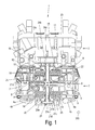
- FIG. 1 shows a schematic sectional view of a first embodiment of a test and terminal device assembly.
- the arrangement 1 is a test and connection device arrangement and comprises a test device 2 and a connection device 3.
- the test device 2 is provided for insertion into the connection device 3 and serves for testing and measuring electrical values of electrical devices connected to the connection device 3, which will not be described in detail.
- the test apparatus 2 has a scholarvoriquessgephase 23 and is not shown in detail. In the housing not described further plug-in and switching devices for testing and / or measuring purposes are arranged. At the bottom of the test device 2 pin elements 24 are mounted, of which only one example is shown here by way of example for all others. With these pin elements 24 and possibly other plugs, which will not be discussed further, the test device 2 is inserted into the connection device 3.
- connection device 3 is provided for mounting on a mounting rail 25 and fixed with its underside thereon in the longitudinal direction 333 of the connection device 3, e.g. as shown here by means of holder 4b.
- the holders 4b will be described further below.
- the test device 2 is shown inserted from the top of the connection device 3 forth in the connection device 3.
- the connecting device 3 has in this embodiment (see FIG. 4 and 5 ) seven juxtaposed terminal or connection units 300, of which in FIG. 1 and 2 one with its housing 4 is representative of the other shown in section.
- the connection units 300 are each used to connect electrical lines that are substantially perpendicular to the longitudinal axis of the connection device 3 (which in FIG. 1 and 2 perpendicular to the plane of the drawing) can be inserted on both sides into the connection units 300 and can be fastened in clamping units 5 and 7.
- the clamping units 5 and 7 are shown in this embodiment as a pair, of course, larger pairs are possible.
- the clamping units 5 and 7 are provided here with screws, which can be reached by a respective operating portion 9, 10 from the top of the connecting device 3 ago.
- the clamping unit 5 is connected to a bus bar 6, wherein the opposite clamping unit 7 is mirror-inverted connected to a busbar 8.
- the busbars 6 and 8 lie in one plane and are electrically isolated from each other in a separating element 22 received.
- a first chamber 11 for receiving a first compression spring 15 is arranged in the housing 4.
- a further first chamber 12 for receiving a further first compression spring 16 is formed at the same height.
- Each first compression spring 15, 16 cooperates with a first contact lug 15a, 16a (see FIG. 3 ), which are arranged between the first compression spring 15, 16.
- the inserted pin member 24 of the test apparatus 2 which will be discussed in more detail below becomes. Without inserted pin element 24, ie without inserted test device 2, the two first compression springs 15 and 16 press the first contact lugs 15a, 16a against each other ( FIG. 3 ) and establish between them an electrically conductive contact, which is inserted with the test device 2 (as in FIG. 1 shown) is interrupted by the pin member 24.
- the pin member 24 is attached to or integrally formed with a connection 24a on the underside of the tester housing 23. It is representative of more.
- the connection 24a is followed by a pin body 24b with a pin tip 24c.
- the pin element 24 of the test device 2 is inserted through a first opening 19 a of a first opening portion 19 of the housing 4 of the connection device 3 between the first compression springs 15 and 16.
- the first opening portion 19 is located at the top of the housing 4 of the connecting device 3.
- the pen tip 24c is used during insertion for threading and pressing apart the first contact lugs 15a and 16a of the first compression springs 15 and 16 and is received in the inserted state in the separating element 22, which for this purpose has a receptacle which corresponds to the pen tip 24c.
- the pin body 24b In the inserted state, the first contact lugs 15a and 16a are pressed by the first compression springs 15 and 16 with their contact portions separated by the pin element 24 against the pin body 24b, which is designed to be electrically insulating.
- the pin body 24b When inserting the pin body 24b between the contact lugs 15a, 16a, the pin body 24b therefore separates the electrical connection between the contact lugs 15a, 16a.
- Particularly preferred are on the pin body 24 b but each at the contact lugs 15 a, 16 a side facing electrically conductive contact plates 24 d (s. Fig. 9b ), which pick off a voltage applied in each case to the contact lugs 15a, 16a, so that a current circuit flowing via the contact lugs 15a, 16a is indeed interrupted.
- the contact plates 24d are provided with different measuring meters 33 (see FIG. Fig. 9b ), so that, for example, the voltage applied to the contact lugs 15a, 16a, the current flowing over the contact lugs 15a, 16a, a frequency, a power, a resistance or the like can be measured.
- the first compression springs 15 and 16 are inserted in the first chambers 11 and 12 under bias, so that a certain contact pressure of the first contact lugs 15a and 16a is present during their contacting.
- a second chamber 13 is arranged with a second compression spring 17 below the busbar 6 in the housing 4.
- On the left side is at the same height another second chamber 14 for receiving a further second Compression spring 18 formed.
- the second compression springs 17 and 18 are associated with the first compression springs 15 and 16 second contact lugs 17 a and 18 a (see FIG. 3 and 7 ).
- the second compression springs 17 and 18 are electrically connected in parallel with the first compression springs 15, 16. So that when plugged test device 2 and an electrical contact of the second contact lugs 17a and 18a of the second compression springs 17, 18 is interrupted, between the contact portions of the second contact lugs 17a and 18a of the second compression springs 17, 18, a plug element 21 is inserted.
- the second compression springs 17 and 18 are used in the second chambers 13 and 14 under bias to produce a certain contact pressure in the contacting of the second contact lugs 17 a and 18 a.
- the plug-in element 21 is formed like a nail, has a head 21 a and an adjoining shaft 21 b with a tip 21 c. It is shown as representative of others and inserted through a second opening 20a of a second opening portion 20 of the housing 4 on the underside thereof between the second compression springs 17 and 18.
- the tip 21 c is used during insertion for threading and pushing apart the second contact lugs 17a and 18a of the second compression springs 17 and 18 and is included in the inserted state in the separator 22, which analogous to the pen tip 24c of the pin member 24 has a receptacle which with the Peak 21 c corresponds.
- the second compression springs 17 and 18 rest with their contact sections separated by the plug-in element 21 on the shaft 21b, which is designed to be electrically insulating.
- the connecting device 3 is not only suitable for use on mounting rails 25, but also for other types of mounting, as in FIG. 2 in a schematic sectional view of a second embodiment of the test and terminal device assembly 1 is shown.
- connection device 3 is in this case attached with its underside on one side to a wall element 26 with wall openings 26a and wall cutouts 26b.
- the supports 4a of the housing 4 pass through the wall openings 26a, wherein the second opening portion 20 of the housing 4 on its underside protrudes through the wall cutout 26b.
- the test device 2 is arranged on the other side of the wall element 26, wherein its pin element 24 is inserted through the second opening 20a of the second opening portion 20 between the second contact lugs 17a and 18a of the second compression springs 17 and 18 of the second chambers 13 and 14.
- the test device 2 is thus inserted on the underside of the connection device 3 in this.
- the supports 4a of the connection device 3 rest on the underside of the test device 2, so that the test device 2 and the connection device 3 are defined spaced from each other.
- the plug-in element 21 is inserted in this second embodiment from the top of the connection device 3 through the first opening portion 19 between the first contact lugs 15a and 16a of the first compression springs 15 and 16 for the separation thereof.
- connection device 3 can be plugged together on both sides with the test device 2.
- connection device 3 is provided for mounting rail mounting, it is equipped with the plug-in elements 21 from the bottom.
- the plug-in elements 21 are inserted from the top of the connection device 3.
- FIG. 3 shows a schematic sectional view of the second embodiment according to FIG. 2 with first and second contact lugs 15a, 16a, 17a, 18a.
- the first and second contact lugs 15a, 16a and 17a, 18a face each other as pairs between the first compression springs 15 and 16 and the second compression springs 17, 18.
- the second contact lugs 15a and 16a contact, since no plug-in element 21 is inserted yet.
- the first and second contact lugs 15a, 16a and 17a, 18a have spring portions 15b, 16b, 17b, 18b, with which they are each electrically fixed to the busbars 6 and 8. Therefore, in each case the mirror image of the busbars 6, 8 opposite each other contact lugs 15a, 17a and 16a, 18a by the busbars 6, 8 connected electrically contacting each other.
- the contact lugs 15a and 17a are connected to the bus bar 6, and the tabs 16a and 18a are connected to the bus bar 8.
- FIG. 3 the upper, first contact lugs 15a and 16a are shown without plug-in element 21, wherein the lower, second contact lugs 17a and 18a are pushed apart by the pin element 24.
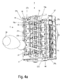
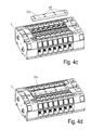
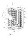
- FIG. 4 shows in a a schematic perspective view of an embodiment of a connecting device 3 with a tamper-evident in a first position, in b the placement of the tamper protection and FIG. 5 shows this manipulation protection in a second position.
- connection device 3 in this exemplary embodiment has seven clamping or connection units 300 arranged next to one another.
- first opening sections 19 with the first openings 19a can be seen.
- the first compression springs 15, 16 are arranged cooperatively with contact lugs 15a, 16a, of which only the contact lugs 16a cooperating with the first compression springs 16 can be seen.
- elongated protective elements 27 are arranged on both longitudinal sides on the clamping units 5, 7 (which are not visible), which are held longitudinally displaceable in guides 4c of the housing 4 in the longitudinal direction of the connecting device 3.
- the protective elements 27 are arranged in opposite directions.
- the protective elements 27 are in the first, closed position, i. the operating portions 9 and 10 of the clamping units 5, 7 are located below the protective elements 27 and are not accessible.
- the protective elements 27 have per clamping unit 5, 7 in each case a cover panel 27c with a cover opening 27d. So that the operating sections 9 and 10 of the clamping units can be made accessible, the protective elements 27 are displaceable in the direction of the arrows in opposite directions by means of a tool 28 via their actuating parts 27a in the second position.
- the clamping units 5, 7 are formed here as drawbar connections (s. Fig. 1 ).
- the invention is not limited to this training. But those Clamping units 5, 7 can also be designed with a different connection technology, for example as tension spring connections.
- the connecting device 3 offers the possibility of electrically connecting a plurality of clamping units 5, 7 via transverse connectors 70.
- the cross connectors 70 like the Fig. 4 (b) shows, inserted during the assembly process below the protective elements 27 in the operating sections 9, 10 in a plug-in direction 700, so that in each case a plug contact 71 of the cross connector 70 engages in an operating section 9, 10 and the cross connector 70, the operating sections 9, 10, in which the Plug contacts 71 are inserted, electrically connected to each other.
- the protective element 27 is inserted after insertion of the cross connector 70 in the guides 4c, so that the cross connector 70 is inaccessible in the delivery state of the connecting device 3.
- the protective elements 27 are shifted so that the cover openings 27d of the cover panels 27c on the operating sections 9 and 10 of the clamping units 5, 7 are arranged and access to the clamping units 5, 7, for example with the tool (screwdriver) is possible.
- the actuating parts 27a of the protective elements 27 are arranged at a distance from the stops 4d of the housing 4.
- the Fig. 4c - d and e - f each show arranging a cover 27e to the first opening portion 19 to protect the first openings 19a, through which the first contact lugs 16a are accessible, against the ingress of dust.
- the cover 27e of Fig. 4c and d has latching recesses 27f so that it can be locked.
- the cover 27e of FIGS. E and f is fixed to the connecting device 3 by means of second seals 27g.
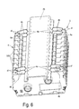
- FIG. 6 shows a schematic perspective view of an embodiment of the connecting device 3 in mounting rail mounting from below.
- double holders 4b are respectively inserted or latched into the housing 4 in four corner regions on the underside of the housing 4 of the connection device 3.
- Each holder 4b has an inwardly to the support rail 25 facing end with a support rail holding portion 4e in the form of a nose.
- the holders 4b are formed with arm-shaped wall holding portions 4f.
- the holders 4b are optionally coverable with separate covers (not shown).
- connection device 3 is held by means of the support rail holding portion 4e of the holder 4b on the support rail 25 by the support rail holding portion 4e engage over a portion of the support rail 25.
- the holders 4b can be inserted or latched into the corresponding recesses of the housing 4 in the position shown, for example after the connecting device 3 has been applied, or pushed towards one another in the direction of the mounting rail 25 in order to create the overlapping of the mounting rail holding section 4e.
- the connection device 3 can also be pushed onto the support rail 25 in the longitudinal direction of the latter. Other options are of course conceivable.
- the holders 4b have a further holding function by means of the wall holding sections 4f, which in FIG. 7 is shown.
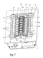
- FIG. 7 shows a schematic perspective view of an embodiment of the connecting device 3 in wall mounting from below.
- the connecting device 3 with its underside in a wall section 26b of the wall element 26 (see also FIG. 2 ) used.
- the outwardly facing wall holding portions 4f of the holder 4b engage over an edge of the wall section 26b of the wall element 26 and hold and fasten the connecting device 3 to the wall element 26.
- the holder 4b can be inserted, for example, in corresponding openings on the bottom of the housing 4 and be locked.
- FIG. 7 is the bottom of the connecting device 3 with the second opening portion 20 and the second openings 20a for insertion of the test apparatus 2 (see FIG. 2 ) clearly visible.
- the ends of the second contact lugs 17a and 18a can be seen.
- connection device 3 is mounted both on a mounting rail 25 and on a wall cutout 26b of a wall element 26.
- the compression springs 15, 16 and 17, 18 are provided at their contact points with contact portions of special contact material or with the contact lugs 15 a, 16 a, 17 a, 18 a cooperate.
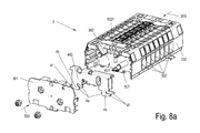
- Fig. 8 shows in Fig. 8a a further embodiment of a connecting device 3.
- the connecting device 3 has the seven terminal units 300.
- holding units 302 are arranged, in each of which a holding element 400 is provided for fastening the connecting device 3 to a support rail 25 or a wall bracket 26.
- the holding units 302 are each closed at the front by means of a closure unit 301.
- the end faces are shown here by arrows 303.
- further connection units 300 can also be positioned between the closure units 301 and the holding units 302.
- further holding units 302 can be positioned between the connection units 300.
- Each of the holding elements 400 has in each case two holder pairs 4b, on each of which a nose-shaped carrier rail holding section 4e, and in each case an elongated wall holding section 4f are provided.
- the holding elements 400 are manufactured in one piece as stamped and bent parts and can be arranged in a receiving space 401 of the holding units 400.
- the Fig. 8b shows by way of example a holding unit 302 without the holding element 400. Instead, a connection element 440 for the holding element 400 is shown.
- the connecting element 440 is formed as a molded part and made for example of a plastic, a light metal or a light metal alloy. It is attached to a displacement means 304, which is designed here as a screw.
- the displacement means 304 is arranged rotatably about an axis in the housing 4 of the holding unit 302.
- a nut 305 is arranged in a defined position, which is screwed onto the displacement means 304. Therefore, by rotating the displacement means 304 in and against a displacement direction 31 extending in the direction of the axis, the connection element 440 is displaceable relative to the housing 4 of the holding unit 302.
- the Fig. 8c and 8d show the holding unit 302 with arranged on the connecting element 440 holding member 400, wherein the Fig. 8c a perspective view and the Fig. 8d show a front view.
- the holding element 400 is fastened to the connection element 440, for example latched. As a result, it is displaceable with the connection element 440 in and against the displacement direction 31.
- a cutout 401 in the holding element 400 is released, through which the arranged on the displacement means 304 nut 305 is visible.
- the holding unit 302 or the holding element 400 is attached to a wall element 26.
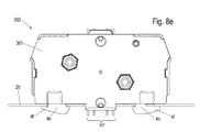
- the Fig. 8e shows the attached to the wall element 26 holding unit 302 with frontally arranged closure unit 301.
- the holding unit 302 which is closed at the end by means of the closure unit 301, is arranged on a hat-shaped mounting rail 25 instead of on a wall element 26.
- the Fig. 8g - i show the positioning of the holding unit 302 on a wall element 26 by way of example.
- the holders 4b arranged on a side I of the holding unit 302 or the connecting device 3 are guided through a wall opening 26a of the wall element 26, so that the wall holding sections 4f engage behind the wall element 26. Subsequently, the holders 4b of the other side II are guided by rotation in a rotational direction 4g through the wall opening 26a. Thereafter, the holding unit 302 or the connecting device 3 is displaced so that the wall holding portions 4f of the other side engage behind the wall element. Subsequently, the holding element 302 or the connection device 3 is displaced relative to the housing 4 by rotating the displacement means 304 until the holding element 302 or the connection device 3 is fixed to the wall element 26.
- connection device 3 has a plurality of connection units 300 for connecting electrical conductors, which are arranged in a row.
- connection device 3 has a bottom side 306 (see FIG. Fig. 7 ).
- an adapter plate 9 which has a cutout 90 for receiving elements 4a, 4b, 307 of the connection device 3.
- elements are, for example, supports 4a, holder 4b for fastening the connection device 3 to a mounting rail 25 and / or into a wall cutout 26b, or contact regions 307 (see FIG. Fig. 7 ), in which, for example, electrical contacts 17a, 18a are provided.
- the height 4h (s. Fig. 8c ) of these elements 4a, 4b, 307 is smaller than the thickness 91 of the adapter plate 9 (s. Fig. 9c ), so that the adapter plate 9 completely accommodates the elements 4a, 4b, 307 when the connection device 3 is mounted on the adapter plate 9.
- the connecting device 3 shown here has the holder 4b for attaching the connecting device 3 to the mounting rail 25 or in the wall cutout 26b.
- holder 4b for attaching the connecting device 3 to the mounting rail 25 or in the wall cutout 26b.
- an embodiment which does not include such holders 4b is preferred.
- connection device 3 In order to fasten the connection device 3 to the adapter plate 9, the connection device 3 has screws 304 'with which it can be screwed to the adapter plate 9.
- 9 protrusions 92 are provided on the adapter plate, which are positioned below the screws 304 'and protrude into the cutout 91.
- connecting device 3 analogously to the representation of Fig. 8a two holding units 302, in each of which a holding element 400 is arranged with two pairs of holders 4b (s. Fig. 8c ).
- the invention can also be used for connecting devices 3, which indeed have holders 4b for fastening the connecting device 3 to a mounting rail 25 and / or in a wall cutout 26b, but no such retaining elements 400.
- the holding elements 400 each have a receptacle 3021 for a displacement means 304.
- the receptacle 3021 is therefore not only used for attaching the connecting device 3 to the mounting rail 25 and / or the wall cutout 26 b, but also for attaching the connecting device 3 to the adapter plate.
- Fig. 9c shows the arrangement of closed wall 900, adapter plate 9 and connecting device 3.
- the adapter plate 9 is first attached to the closed wall 900. Subsequently, the connecting device 3 is placed on the adapter plate 9 and screwed with this.
- the surface contour of the lower side 306 of the connecting device 3 is formed corresponding to a surface contour of the adapter plate 9 on its side 93 facing the connecting device 3.
- the cutout 90 is completely surrounded by an edge region, which forms the adapter plate 9 here.
- the connection device 3 lies over the entire surface of the adapter plate 9, so that penetration of dust and moisture into the cutout 90 is made more difficult.
- connection device 3 rests only in line-shaped or punctiform areas (not shown) on the adapter plate 9, or that the adapter plate 9 recesses (not shown), in which the connection device 3 does not rest on her.
- the Fig. 10a shows a perspective view of the test device 2.
- probes 37 are arranged here.
- the first measuring terminals 29 are arranged at an angle to each other. This allows an unproblematic arranging relatively large probes 37.
- Einsteckfchipe 38, 39 are provided, one of which differs in its cross section. By this Kodiereinsteckfuß 39 incorrect placement of the test device 2 in the connection device 3 is avoided.
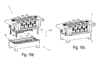
- a contact protection cover 8 is provided into which the test device 2 can be inserted.
- the contact protection cover 8 has first and second recesses 80, 81 for protecting the Einsteckfborne 38 and the Kodiereinsteckfußes 39 and the pin members 24.
- the Fig. 10b and c show the placement of the test device 2 in the contact protection cover 8 in the insertion direction 801, wherein the Fig. 10c the inserted into the contact protection cover 8 tester 2 shows.
Landscapes
- Connections Arranged To Contact A Plurality Of Conductors (AREA)
- Connector Housings Or Holding Contact Members (AREA)
- Multi-Conductor Connections (AREA)
Abstract
Description
- Die Erfindung betrifft eine Anordnung aus einer Adapterplatte und einer an die Adapterplatte montierten Anschlussvorrichtung nach den Merkmalen des Patentanspruchs 1.
- In der Steuerungstechnik werden häufig Anschlussvorrichtungen aus einer Vielzahl aneinander reihbarer Anschlusseinheiten verwendet, die zum Anschluss elektrischer Leiter vorgesehen sind. Solche Anschlussvorrichtungen ermöglichen einem Monteur, beispielsweise bei einem Produktwechsel in einer Fertigungsstraße, ein schnelles Umkonfigurieren. Zumeist werden die Anschlussvorrichtungen auf Tragschienen angeordnet, von denen sie durch wenige Handgriffe abnehmbar sind. Häufig ist auch eine Montage in Wandausschnitte möglich.
- Die Aufgabe der vorliegenden Erfindung ist es, eine Anordnung bereitzustellen, die eine Montage einer solchen Anschlussvorrichtung an eine geschlossene Wand ermöglicht.
- Diese Aufgabe wird durch eine Anordnung mit den Merkmalen des Anspruchs 1 gelöst.
- Die erfindungsgemäße Anordnung umfasst bevorzugt eine Adapterplatte und eine an die Adapterplatte montierte Anschlussvorrichtung zum Anschluss elektrischer Leiter, wobei die Anschlussvorrichtung mehrere aneinander gereihte Anschlusseinheiten aufweist, und wobei die Anschlussvorrichtung eine Unterseite aufweist, mit der sie zumindest teilweise auf der Adapterplatte (9) aufliegt.
- Die Adapterplatte ermöglicht eine Befestigung der Anschlussvorrichtung auf einem Untergrund. Bevorzugt ist sie an ihrer der Anschlussvorrichtung abgewandten Seite eben ausgebildet, so dass sie zur Montage der Anschlussvorrichtung auf einem ebenen Untergrund vorgesehen ist. Prinzipiell ist aber auch eine Oberflächenkontur der der Anschlussvorrichtung abgewandten Seite der Adapterplatte bevorzugt, die an eine Oberflächenkontur des Untergrundes angepasst und uneben vorgesehen ist.
- In einer bevorzugten Ausführungsform weist die Adapterplatte einen Ausschnitt zur Aufnahme von Elementen der Anschlussvorrichtung auf. Dadurch werden Elemente der Anschlussvorrichtung, die gegenüber einer fiktiven Befestigungsebene erhaben sind, in den Ausschnitt aufgenommen.
- Durch den zur Aufnahme der Elemente vorgesehenen Ausschnitt in der Adapterplatte ist die Anschlussvorrichtung auf einen Untergrund, vorzugsweise an eine Wand, montierbar, ohne die Elemente zu beschädigen. Dafür ist die Höhe der in den Ausschnitt aufgenommenen Elemente bevorzugt kleiner als die Dicke der Adapterplatte. Besonders bevorzugt ist die Anordnung auf eine geschlossene Wand montiert.
- Es ist bevorzugt, dass die Adapterplatte an ihrer der Anschlussvorrichtung zugewandten Seite eine Oberflächenkontur aufweist, die zumindest teilweise zu einer Oberflächenkontur der Unterseite der Anschlussvorrichtung korrespondierend ausgebildet ist. Ganz besonders bevorzugt liegt die Anschlussvorrichtung zumindest teilweise, vorzugsweise mit einem Randbereich, vollflächig auf der Adapterplatte auf. In dieser Ausführungsform folgt die Oberflächenkontur der Adapterplatte in dem Randbereich der Oberflächenkontur der Anschlussvorrichtung. Es ist bevorzugt, dass der Randbereich geschlossen ausgebildet ist, so dass er den Ausschnitt vollumfänglich umgibt. Das Eindringen von Staub und Feuchtigkeit in den Ausschnitt wird dadurch behindert.
- In einer bevorzugten Ausführungsform weist die Anschlussvorrichtung als in den Ausschnitt aufgenommene Elemente zumindest zwei Halter auf, die zum Befestigen der Anschlussvorrichtung an eine Tragschiene und/oder in einen Wandausschnitt vorgesehen sind. Die Anschlussvorrichtung dieser Ausführungsform ist daher alternativ entweder an die Tragschiene, in den Wandausschnitt oder auf die geschlossenen Wand montierbar.
- In einer bevorzugten Ausführungsform weisen die Halter Tragschienenhalteabschnitte für eine Tragschienenmontage der Anschlussvorrichtung und Wandhalteabschnitte für eine Wandmontage der Anschlussvorrichtung in den Wandausschnitt auf, so dass sowohl die Tragschienenmontage als auch die Wandmontage in den Wandausschnitt sehr leicht durchführbar ist.
- Zudem ist die Anschlussvorrichtung bevorzugt auf die Adapterplatte aufschraubbar oder aufrastbar, und daher ebenfalls sehr leicht an die geschlossene Wand montierbar.
- Für die Montage der Anschlussvorrichtung weist diese vorzugsweise eine an die Anschlusseinheiten anreihbare Halteeinheit auf, in der ebenfalls bevorzugt ein Halteelement mit je zwei Halterpaaren angeordnet ist. Weiterhin ist es bevorzugt, dass die Anschlussvorrichtung zwei solche Halteeinheiten aufweist, die besonders bevorzugt an gegenüberliegenden Enden der Anschlussvorrichtung angeordnet sind, so dass sie voneinander beabstandet sind.
- Es ist bevorzugt, dass die Halteeinheit eine Aufnahme für ein Verschiebemittel, insbesondere eine Schraube, umfasst. Bevorzugt wird die Anschlussvorrichtung mit dem Verschiebemittel an der Adapterplatte befestigt.
- In einer Ausführungsform, in der die Anschlussvorrichtung die Halter für die Tragschienenmontage und die Wandmontage umfasst, ist es bevorzugt, dass das Verschiebemittel zum Verstellen des Halteelementes gegen die Montagerichtung genutzt wird, so dass es auch zum Befestigen der Anschlussvorrichtung an der Tragschiene oder dem Wandausschnitt dient.
- In einer bevorzugten Ausführungsform weist die Anschlussvorrichtung zwei sich elektrisch kontaktierende Kontaktfahnen auf. Die Kontaktfahnen sind bevorzugt zum Einstecken einer Prüfvorrichtung vorgesehen, wobei die Kontaktfahnen beim Einstecken der Prüfvorrichtung getrennt werden.
- Bei in die Anschlussvorrichtung eingesteckter Prüfvorrichtung liegt daher bevorzugt die an den Kontaktfahnen anliegende Spannung an den Kontaktplatten der Verbindungseinheiten an.
- In einer Ausführung ist vorgesehen, dass die Prüfvorrichtung von einer Oberseite der Anschlussvorrichtung und von einer Unterseite der Anschlussvorrichtung in die Anschlussvorrichtung einsteckbar ist. Dadurch ist es möglich, die Anordnung vielseitiger einzusetzen.
- Eine noch weitere Ausführung sieht vor, dass die Anschlussvorrichtung zum beidseitigen Einstecken einer Prüfvorrichtung von einer Oberseite der Anschlussvorrichtung und einer Unterseite der Anschlussvorrichtung mit ersten und zweiten Kontaktfahnen ausgebildet ist. Wenn die zweiten Kontaktfahnen mit den ersten sich elektrisch kontaktierenden Kontaktfahnen übereinander angeordnet sind, ergibt sich eine größere Anbringungsmöglichkeit der Prüfvorrichtung, wobei zusätzliche oder umständliche Konstruktionen nicht mehr notwendig sind.
- In einer weiteren Ausführung sind die zweiten Kontaktfahnen und die ersten sich elektrisch kontaktierenden Kontaktfahnen elektrisch parallel geschaltet. Dies ist in einfacher Weise innerhalb der Anschlussvorrichtung möglich, wodurch diese in ihrem Volumen nicht vergrößert wird.
- Dabei ist es zweckmäßig, wenn die zweiten Kontaktfahnen oder die ersten sich elektrisch kontaktierenden Kontaktfahnen mit einem wieder entfernbaren Steckelement elektrisch getrennt sind. Dieses wieder entfernbare Steckelement ermöglicht es, die Anschlussvorrichtung ihrem Einsatzzweck entsprechend einfach durch Umstecken anzupassen, ohne dass eine andere Konstruktion erforderlich ist.
- In einer noch weiteren Ausführung weist die Anschlussvorrichtung mindestens ein Schutzelement auf, welches aus einer ersten Stellung, in welcher es Betätigungsabschnitte für darunter angeordnete Klemmeinheiten der Anschlussvorrichtung verschließt, in eine zweite Stellung verstellbar ist, in welcher die Betätigungsabschnitte zugänglich sind. Damit ist ein einfacher und schneller Manipulationsschutz ermöglicht.
- In einer weiteren Ausführung ist das mindestens eine Schutzelement in einer Führung eines Gehäuses der Anschlussvorrichtung in Längsrichtung der Anschlussvorrichtung verschiebbar gehalten. Eine solche Ausgestaltung ist einfach und dabei kann das Schutzelement leicht und schnell verstellt werden.
- Es ist dabei vorgesehen, dass das mindestens eine Schutzelement jeweils ein Abdeckfeld mit einer Abdecköffnung pro Klemmeinheit aufweist. Auf diese Weise kann ein Schutzelement für eine bestimmte Anzahl von Klemmeinheiten durch einfaches Ablängen angepasst werden.
- Anhand einer beispielhaften Ausführung wird die Erfindung mit Bezug auf die beigefügten Zeichnungen näher erläutert. Hierbei zeigen:
- Figur 1
- eine schematische Schnittansicht eines ersten Ausführungsbeispiels einer Prüf- und Anschlussvorrichtungsanordnung mit an einer Tragschiene angeordneter Anschlussvorrichtung;
- Figur 2
- eine schematische Schnittansicht eines zweiten Ausführungsbeispiels der Prüf- und Anschlussvorrichtungsanordnung mit an einem Wandelement angeordneter Anschlussvorrichtung;
- Figur 3
- eine schematische Schnittansicht eines weiteren Ausführungsbeispiels einer Prüf- und Anschlussvorrichtungsanordnung mit analog der
Figur 2 an einem Wandelement angeordneter Anschlussvorrichtung, in der Kontaktfahnen sichtbar sind; - Figur 4
- in a eine schematische Perspektivansicht eines Ausführungsbeispiels einer Anschlussvorrichtung mit einem Manipulationsschutz in einer ersten Stellung, in b eine schematische Perspektivansicht eines weiteren Ausführungsbeispiels einer erfindungsgemäßen Anschlussvorrichtung während eines Montagezustandes, in c - d und in e - f jeweils das Abdecken der Kontaktfahnen der Anschlussvorrichtung durch eine Staubschutzabdeckung;
- Figur 5
- das Ausführungsbeispiel nach
Figur 4 mit dem Manipulations-schutz in einer zweiten Stellung; - Figur 6
- eine schematische Perspektivansicht eines Ausführungsbeispiels der Anschlussvorrichtung bei Tragschienenmontage von unten;
- Figur 7
- eine schematische Perspektivansicht eines Ausführungsbeispiels der Anschlussvorrichtung bei Wandmontage von unten;
- Figur 8
- verschiedene Ansichten eines Ausführungsbeispiels einer Anschlussvorrichtung;
- Figur 9
- in a - c das Aufsetzen der Anschlussvorrichtung auf eine Adapterplatte; und
- Figur 10
- in a die Prüfvorrichtung in einer perspektivischen Ansicht und in b und c das Aufsetzen der Prüfvorrichtung auf eine Kontaktschutz-abdeckung.
-
Figur 1 zeigt eine schematische Schnittansicht eines ersten Ausführungsbeispiels einer Prüf- und Anschlussvorrichtungsanordnung 1. - Die Anordnung 1 ist eine Prüf- und Anschlussvorrichtungsanordnung und umfasst eine Prüfvorrichtung 2 und eine Anschlussvorrichtung 3.
- Die Prüfvorrichtung 2 ist zum Einstecken in die Anschlussvorrichtung 3 vorgesehen und dient zur Prüfung und Messung elektrischer Werte von an der Anschlussvorrichtung 3 angeschlossenen elektrischen Geräten, die nicht näher beschrieben werden sollen.
- Die Prüfvorrichtung 2 weist ein Prüfvorrichtungsgehäuse 23 auf und ist nicht näher dargestellt. In dem Gehäuse sind nicht weiter beschriebene Steck- und Schalteinrichtungen für Prüf- und/oder Messzwecke angeordnet. An der Unterseite der Prüfvorrichtung 2 sind Stiftelemente 24 angebracht, von denen hier beispielhaft stellvertretend für alle anderen nur eines gezeigt ist. Mit diesen Stiftelementen 24 und gegebenenfalls weiteren Steckern, auf die nicht weiter eingegangen werden soll, wird die Prüfvorrichtung 2 in die Anschlussvorrichtung 3 eingesteckt.
- In diesem ersten Ausführungsbeispiel ist die Anschlussvorrichtung 3 für die Montage auf einer Tragschiene 25 vorgesehen und mit ihrer Unterseite auf dieser in Längsrichtung 333 der Anschlussvorrichtung 3 befestigt, z.B. wie hier gezeigt mittels Halter 4b. Die Halter 4b werden weiter unten noch weiter beschrieben. Die Prüfvorrichtung 2 ist von der Oberseite der Anschlussvorrichtung 3 her in die Anschlussvorrichtung 3 eingesteckt gezeigt.
- Die Anschlussvorrichtung 3 weist in diesem Ausführungsbeispiel (siehe
Figur 4 und5 ) sieben nebeneinander angeordnete Klemm- bzw. Anschlusseinheiten 300 auf, von denen inFigur 1 und2 eine mit ihrem Gehäuse 4 stellvertretend für die anderen im Schnitt gezeigt ist. Die Anschlusseinheiten 300 dienen jeweils zum Anschluss elektrischer Leitungen, die im Wesentlichen rechtwinklig zur Längsachse der Anschlussvorrichtung 3 (welche inFigur 1 und2 senkrecht auf der Zeichnungsebene steht) beidseitig in die Anschlusseinheiten 300 einführbar und in Klemmeinheiten 5 und 7 befestigbar sind. Die Klemmeinheiten 5 und 7 sind in diesem Ausführungsbeispiel als ein Paar gezeigt, selbstverständlich sind auch größere Paarzahlen möglich. Die Klemmeinheiten 5 und 7 sind hier mit Schrauben versehen, welche durch einen jeweiligen Betätigungsabschnitt 9, 10 von der Oberseite der Anschlussvorrichtung 3 her erreichbar sind. Die Klemmeinheit 5 ist mit einer Stromschiene 6 verbunden, wobei die gegenüberliegende Klemmeinheit 7 spiegelbildlich mit einer Stromschiene 8 verbunden ist. Die Stromschienen 6 und 8 liegen in einer Ebene und sind elektrisch voneinander isoliert in einem Trennelement 22 aufgenommen. - Oberhalb der Stromschiene 6 ist in dem Gehäuse 4 eine erste Kammer 11 zur Aufnahme einer ersten Druckfeder 15 angeordnet. Auf der linken Seite ist auf gleicher Höhe eine weitere erste Kammer 12 zur Aufnahme einer weiteren ersten Druckfeder 16 eingeformt. Jede erste Druckfeder 15, 16 wirkt mit einer ersten Kontaktfahne 15a, 16a zusammen (siehe
Figur 3 ), welche zwischen den ersten Druckfeder 15, 16 angeordnet sind. In derFigur 1 befindet sich zwischen den ersten Kontaktfahnen 15a, 16a (die hier nicht zu sehen sind, sieheFigur 3 ) und den Druckfedern das eingesteckte Stiftelement 24 der Prüfvorrichtung 2, auf welches unten noch näher eingegangen wird. Ohne eingestecktes Stiftelement 24, d.h. ohne eingesteckte Prüfvorrichtung 2, drücken die beiden ersten Druckfedern 15 und 16 die ersten Kontaktfahnen 15a, 16a gegeneinander (Figur 3 ) und stellen zwischen diesen einen elektrisch leitenden Kontakt her, der bei eingesteckter Prüfvorrichtung 2 (wie inFigur 1 gezeigt) durch das Stiftelement 24 unterbrochen ist. - Das Stiftelement 24 ist mit einer Verbindung 24a an der Unterseite des Prüfvorrichtungsgehäuses 23 angebracht oder mit diesem einstückig ausgebildet. Es steht stellvertretend für weitere. An die Verbindung 24a schließt sich ein Stiftkörper 24b mit einer Stiftspitze 24c an. Das Stiftelement 24 der Prüfvorrichtung 2 ist durch eine erste Öffnung 19a eines ersten Öffnungsabschnitts 19 des Gehäuses 4 der Anschlussvorrichtung 3 hindurch zwischen die ersten Druckfedern 15 und 16 gesteckt. Der erste Öffnungsabschnitt 19 befindet sich an der Oberseite des Gehäuses 4 der Anschlussvorrichtung 3. Die Stiftspitze 24c dient beim Einstecken zum Einfädeln und Auseinanderdrücken der ersten Kontaktfahnen 15a und 16a der ersten Druckfedern 15 und 16 und ist im eingesteckten Zustand in dem Trennelement 22 aufgenommen, welches dazu eine Aufnahme aufweist, die mit der Stiftspitze 24c korrespondiert. Im eingesteckten Zustand ruhen die ersten Kontaktfahnen 15a und 16a gedrückt durch die ersten Druckfedern 15 und 16 mit ihren durch das Stiftelement 24 getrennten Kontaktabschnitten an dem Stiftkörper 24b, welcher elektrisch isolierend ausgebildet ist. Beim Einstecken des Stiftkörper 24b zwischen die Kontaktfahnen 15a, 16a trennt der Stiftkörper 24b daher die elektrische Verbindung zwischen den Kontaktfahnen 15a, 16a. Besonders bevorzugt sind am Stiftkörper 24b aber jeweils an der den Kontaktfahnen 15a, 16a zugewandten Seite elektrisch leitende Kontaktplatten 24d(s.
Fig. 9b ) angeordnet, die eine jeweils an den Kontaktfahnen 15a, 16a anliegende Spannung abgreifen, so dass ein über die Kontaktfahnen 15a, 16a fließender Stromkreis zwar unterbrochen wird. In der oder über die Prüfvorrichtung 2 sind die Kontaktplatten 24d jedoch mit verschiedenen Messmetern 33 (s.Fig. 9b ) verbindbar, so dass beispielsweise die an den Kontaktfahnen 15a, 16a anliegende Spannung, der über die Kontaktfahnen 15a, 16a fließende Strom, eine Frequenz, eine Leistung, ein Widerstand oder ähnlich messbar sind. - Die ersten Druckfedern 15 und 16 sind in den ersten Kammern 11 und 12 unter Vorspannung eingesetzt, sodass ein bestimmter Kontaktdruck der ersten Kontaktfahnen 15a und 16a bei ihrer Kontaktierung vorhanden ist.
- In gleicher Weise ist unterhalb der Stromschiene 6 in dem Gehäuse 4 eine zweite Kammer 13 mit einer zweiten Druckfeder 17 angeordnet. Auf der linken Seite ist auf gleicher Höhe eine weitere zweite Kammer 14 zur Aufnahme einer weiteren zweiten Druckfeder 18 eingeformt. Den zweiten Druckfedern 17 und 18 sind wie den ersten Druckfedern 15 und 16 zweite Kontaktfahnen 17a und 18a zugeordnet (siehe
Figur 3 und7 ). Die zweiten Druckfedern 17 und 18 sind elektrisch mit den ersten Druckfedern 15, 16 parallel geschaltet. Damit bei eingesteckter Prüfvorrichtung 2 auch ein elektrischer Kontakt der zweiten Kontaktfahnen 17a und 18a der zweiten Druckfedern 17, 18 untereinander unterbrochen wird, ist zwischen den Kontaktabschnitten der zweiten Kontaktfahnen 17a und 18a der zweiten Druckfedern 17, 18 ein Steckelement 21 eingesetzt. - Auch die zweiten Druckfedern 17 und 18 sind in den zweiten Kammern 13 und 14 unter Vorspannung eingesetzt, um einen bestimmten Kontaktdruck bei der Kontaktierung der zweiten Kontaktfahnen 17a und 18a zu erzeugen.
- Das Steckelement 21 ist nagelartig ausgebildet, weist einen Kopf 21 a und einen sich daran anschließenden Schaft 21 b mit einer Spitze 21 c auf. Es ist stellvertretend für weitere gezeigt und durch eine zweite Öffnung 20a eines zweiten Öffnungsabschnitts 20 des Gehäuses 4 an dessen Unterseite hindurch zwischen die zweiten Druckfedern 17 und 18 gesteckt. Die Spitze 21 c dient beim Einstecken zum Einfädeln und Auseinanderdrücken der zweiten Kontaktfahnen 17a und 18a der zweiten Druckfedern 17 und 18 und ist im eingesteckten Zustand in dem Trennelement 22 aufgenommen, welches dazu analog zur Stiftspitze 24c des Stiftelementes 24 eine Aufnahme aufweist, die mit der Spitze 21 c korrespondiert. Im eingesteckten Zustand ruhen die zweiten Druckfedern 17 und 18 mit ihren durch das Steckelement 21 getrennten Kontaktabschnitten an dem Schaft 21 b, welcher elektrisch isolierend ausgebildet ist.
- Durch die ersten und zweiten Kammern 11, 12 und 13, 14 ist die Anschlussvorrichtung 3 nicht nur für die Verwendung zur Montage auf Tragschienen 25 geeignet, sondern auch für andere Montagearten, wie in
Figur 2 in einer schematische Schnittansicht eines zweiten Ausführungsbeispiels der Prüf- und Anschlussvorrichtungsanordnung 1 dargestellt ist. - Die Anschlussvorrichtung 3 ist hierbei mit ihrer Unterseite auf einer Seite an einem Wandelement 26 mit Wandöffnungen 26a und Wandausschnitten 26b angebracht. Die Auflagen 4a des Gehäuses 4 treten durch die Wandöffnungen 26a hindurch, wobei der zweite Öffnungsabschnitt 20 des Gehäuses 4 an dessen Unterseite durch den Wandausschnitt 26b hervortritt.
- Die Prüfvorrichtung 2 ist auf der anderen Seite des Wandelementes 26 angeordnet, wobei ihr Stiftelement 24 durch die zweite Öffnung 20a des zweiten Öffnungsabschnitts 20 zwischen die zweiten Kontaktfahnen 17a und 18a der zweiten Druckfedern 17 und 18 der zweiten Kammern 13 und 14 eingesteckt ist. Die Prüfvorrichtung 2 ist somit auf der Unterseite der Anschlussvorrichtung 3 in diese eingesteckt. Dabei ruhen die Auflagen 4a der Anschlussvorrichtung 3 auf der Unterseite der Prüfvorrichtung 2, so dass die Prüfvorrichtung 2 und die Anschlussvorrichtung 3 definiert voneinander beabstandet sind.
- Das Steckelement 21 ist in diesem zweiten Ausführungsbeispiel von der Oberseite der Anschlussvorrichtung 3 durch den ersten Öffnungsabschnitt 19 zwischen die ersten Kontaktfahnen 15a und 16a der ersten Druckfedern 15 und 16 zur Trennung derselben eingesteckt.
- Die weiteren Funktionselemente und -gruppen sind bereits im Zusammenhang mit
Figur 1 beschrieben. - Somit kann die Anschlussvorrichtung 3 beidseitig mit der Prüfvorrichtung 2 zusammengesteckt werden.
- Ist die Anschlussvorrichtung 3 für Tragschienenmontage vorgesehen, wird sie mit den Steckelementen 21 von der Unterseite her bestückt. Bei z.B. einer Wandmontage, bei welcher die Anschlussvorrichtung 3 am besten von der Unterseite her zugänglich ist, werden die Steckelemente 21 von der Oberseite der Anschlussvorrichtung 3 eingesetzt.
-
Figur 3 zeigt eine schematische Schnittansicht des zweiten Ausführungsbeispiels nachFigur 2 mit ersten und zweiten Kontaktfahnen 15a, 16a, 17a, 18a. - Die ersten und zweiten Kontaktfahnen 15a, 16a und 17a, 18a stehen sich jeweils als Paare zwischen den ersten Druckfedern 15 und 16 und den zweiten Druckfedern 17, 18 gegenüber. Die zweiten Kontaktfahnen 15a und 16a kontaktieren sich, da noch kein Steckelement 21 eingesteckt ist. Die ersten und zweiten Kontaktfahnen 15a, 16a und 17a, 18a weisen Federabschnitte 15b, 16b, 17b, 18b auf, mit welchen sie jeweils auf den Stromschienen 6 und 8 elektrisch leitend befestigt sind. Daher sind jeweils die spiegelbildlich der Stromschienen 6, 8 einander gegenüber liegenden Kontaktfahnen 15a, 17a und 16a, 18a durch die Stromschienen 6, 8 elektrisch kontaktierend miteinander verbunden. Mit anderen Worten sind die Kontaktfahnen 15a und 17a mit der Stromschiene 6 verbunden, und die Kontaktfahnen 16a und 18a sind an die Stromschiene 8 angeschlossen.
- In der
Figur 3 sind die oberen, ersten Kontaktfahnen 15a und 16a ohne Steckelement 21 dargestellt, wobei die unteren, zweiten Kontaktfahnen 17a und 18a durch das Stiftelement 24 auseinandergedrückt sind. -
Figur 4 zeigt in a eine schematische Perspektivansicht eines Ausführungsbeispiels einer Anschlussvorrichtung 3 mit einem Manipulationsschutz in einer ersten Stellung, in b das Anordnen des Manipulationsschutzes undFigur 5 zeigt diesen Manipulationsschutz in einer zweiten Stellung. - Wie bereits oben beschrieben weist die Anschlussvorrichtung 3 in diesem Ausführungsbeispiel sieben nebeneinander angeordnete Klemm- bzw. Anschlusseinheiten 300 auf. In den
Figuren 4a - b und5 sind die ersten Öffnungsabschnitte 19 mit den ersten Öffnungen 19a zu erkennen. In dieser Ausführung sind die ersten Druckfedern 15, 16 mit Kontaktfahnen 15a, 16a zusammenwirkend angeordnet, von denen nur die mit den ersten Druckfedern 16 zusammenwirkenden Kontaktfahnen 16a zu sehen sind. - In dem Gehäuse 4 der Anschlussvorrichtung 3 sind auf beiden Längsseiten über den Klemmeinheiten 5, 7 (die nicht sichtbar sind), längliche Schutzelemente 27 angeordnet, die in Führungen 4c des Gehäuses 4 in Längsrichtung der Anschlussvorrichtung 3 längsverschiebbar gehalten sind. Die Schutzelemente 27 sind gegenläufig angeordnet. Die Schutzelemente 27 befinden sich in der ersten, geschlossenen Stellung, d.h. die Betätigungsabschnitte 9 und 10 der Klemmeinheiten 5, 7 befinden sich unterhalb der Schutzelemente 27 und sind nicht zugänglich.
- In der geschlossenen Stellung liegen die Betätigungsteile 27a der Schutzelemente 27 mit einer Kante an einem Anschlag 4d des Gehäuses 4 an.
- Die Schutzelemente 27 weisen pro Klemmeinheit 5, 7 jeweils ein Abdeckfeld 27c mit einer Abdecköffnung 27d auf. Damit die Betätigungsabschnitte 9 und 10 der Klemmeinheiten zugänglich gemacht werden können, sind die Schutzelemente 27 in den Pfeilrichtungen gegenläufig mittels eines Werkzeugs 28 über ihre Betätigungsteile 27a in die zweite Stellung verschiebbar.
- Die Klemmeinheiten 5, 7 sind hier als Zugbügelanschlüsse ausgebildet (s.
Fig. 1 ). Die Erfindung ist aber nicht auf diese Ausbildung beschränkt. Sondern die Klemmeinheiten 5, 7 können auch mit einer anderen Anschlusstechnik ausgeführt sein, beispielsweise als Zugfederanschlüsse. - Optional bietet die erfindungsgemäße Anschlussvorrichtung 3 die Möglichkeit, mehrere Klemmeinheiten 5, 7 über Querverbinder 70 miteinander elektrisch zu verbinden. Die Querverbinder 70 werden, wie die
Fig. 4(b) zeigt, während des Montageprozesses unterhalb der Schutzelemente 27 in die Betätigungsabschnitte 9, 10 in eine Einsteckrichtung 700 eingesteckt, so dass jeweils ein Steckkontakt 71 des Querverbinders 70 in einen Betätigungsabschnitt 9, 10 eingreift und der Querverbinder 70 die Betätigungsabschnitte 9, 10, in die die Steckkontakte 71 eingesteckt sind, elektrisch miteinander verbindet. Das Schutzelement 27 wird nach dem Einstecken des Querverbinders 70 in die Führungen 4c eingeschoben, so dass der Querverbinder 70 im Auslieferungszustand der Anschlussvorrichtung 3 unzugänglich ist. - In der in
Figur 5 gezeigten zweiten Stellung sind die Schutzelemente 27 so verschoben, dass die Abdecköffnungen 27d der Abdeckfelder 27c über den Betätigungsabschnitten 9 und 10 der Klemmeinheiten 5, 7 angeordnet sind und ein Zugriff auf die Klemmeinheiten 5, 7 z.B. mit dem Werkzeug (Schraubendreher) möglich ist. Dabei sind die Betätigungsteile 27a der Schutzelemente 27 in einem Abstand von den Anschlägen 4d des Gehäuses 4 angeordnet. - Die
Fig. 4c - d unde - f zeigen jeweils das Anordnen einer Abdeckung 27e an den ersten Öffnungsabschnitt 19, um die ersten Öffnungen 19a, durch die die ersten Kontaktfahnen 16a zugänglich sind, gegen das Eindringen von Staub zu schützen. Die Abdeckung 27e derFig. 4c und d weist Rastausnehmungen 27f auf, so dass sie verrastbar ist. Die Abdeckung 27e der Fig. e und f wird mittels zweiter Plomben 27g an der Anschlussvorrichtung 3 festgelegt. -
Figur 6 zeigt eine schematische Perspektivansicht eines Ausführungsbeispiels der Anschlussvorrichtung 3 bei Tragschienenmontage von unten. - In diesem Ausführungsbeispiel sind in vier Eckbereichen an der Unterseite des Gehäuses 4 der Anschlussvorrichtung 3 jeweils doppelte Halter 4b in das Gehäuse 4 eingesteckt bzw. eingerastet. Jeder Halter 4b weist ein nach innen zur Tragschiene 25 weisendes Ende mit einem Tragschienenhalteabschnitt 4e in Form einer Nase auf. An den anderen Enden, welche jeweils nach außen weisen, sind die Halter 4b mit armförmigen Wandhalteabschnitten 4f ausgebildet. Die Halter 4b sind mit separaten Abdeckungen (nicht gezeigt) optional abdeckbar.
- Bei der in
Figur 6 gezeigten Montage der Anschlussvorrichtung 3 auf der Tragschiene 25 wird die Anschlussvorrichtung 3 mittels der Tragschienenhalteabschnitt 4e der Halter 4b an der Tragschiene 25 gehalten, indem die Tragschienenhalteabschnitt 4e einen Abschnitt der Tragschiene 25 übergreifen. Dazu können die Halter 4b z.B. nach aufgebrachter Anschlussvorrichtung 3 in diese in entsprechende Ausnehmungen des Gehäuses 4 in die gezeigte Position eingesteckt bzw. eingerastet werden oder in Richtung Tragschiene 25 aufeinander zu geschoben werden, um das Übergreifen der Tragschienenhalteabschnitt 4e zu schaffen. Die Anschlussvorrichtung 3 kann aber auch in Längsrichtung der Tragschiene 25 auf diese aufgeschoben werden. Andere Möglichkeiten sind natürlich denkbar. - Die Halter 4b weisen mittels der Wandhalteabschnitten 4f eine weitere Haltefunktion auf, die in
Figur 7 dargestellt ist. -
Figur 7 zeigt eine schematische Perspektivansicht eines Ausführungsbeispiels der Anschlussvorrichtung 3 bei Wandmontage von unten. - In diesem Ausführungsbeispiel ist die Anschlussvorrichtung 3 mit ihrer Unterseite in einen Wandausschnitt 26b des Wandelementes 26 (siehe auch
Figur 2 ) eingesetzt. Die nach außen weisenden Wandhalteabschnitte 4f der Halter 4b übergreifen hier einen Rand des Wandausschnitts 26b des Wandelementes 26 und halten und befestigen so die Anschlussvorrichtung 3 an dem Wandelement 26. Zur Montage können die Halter 4b beispielsweise in entsprechende Öffnungen an der Unterseite des Gehäuses 4 eingesteckt und verrastet werden. - In
Figur 7 ist die Unterseite der Anschlussvorrichtung 3 mit dem zweiten Öffnungsabschnitt 20 und den zweiten Öffnungen 20a zum Einstecken der Prüfvorrichtung 2 (sieheFigur 2 ) deutlich zu erkennen. Außerdem sind die Enden der zweiten Kontaktfahnen 17a und 18a zu sehen. - Die Halter 4b ermöglichen somit eine Montage der Anschlussvorrichtung 3 sowohl auf einer Tragschiene 25 als auch an einem Wandausschnitt 26b eines Wandelementes 26.
- Durch das beschriebene Ausführungsbeispiel wird die Erfindung nicht eingeschränkt. Sie ist im Rahmen der angefügten Ansprüche natürlich modifizierbar.
- Es ist denkbar, dass die Druckfedern 15, 16 und 17, 18 an ihren Kontaktstellen mit Kontaktabschnitten aus speziellem Kontaktmaterial versehen sind oder mit den Kontaktfahnen 15a, 16a, 17a, 18a zusammenwirken.
-
Fig. 8 zeigt inFig. 8a eine weitere Ausführungsform einer Anschlussvorrichtung 3. Die Anschlussvorrichtung 3 weist die sieben Anschlusseinheiten 300 auf. Beidseitig der Anschlusseinheiten 300 sind Halteeinheiten 302 angeordnet, in denen jeweils ein Halteelement 400 zum Befestigen der Anschlussvorrichtung 3 an einer Tragschiene 25 oder einer Wandhalterung 26 vorgesehen ist. Die Halteeinheiten 302 sind stirnseitig jeweils mittels einer Verschlusseinheit 301 verschlossen. Die Stirnseiten sind hier durch Pfeile 303 dargestellt. Prinzipiell sind zwischen den Verschlusseinheiten 301 und den Halteeinheiten 302 jeweils auch noch weitere Anschlusseinheiten 300 positionierbar. Zudem sind auch noch weitere Halteeinheiten 302 zwischen die Anschlusseinheiten 300 positionierbar. - Jedes der Halteelemente 400 weist jeweils zwei Halter- Paare 4b auf, an denen jeweils ein nasenförmiger Tragschienenhalteabschnitt 4e, sowie jeweils ein länglicher Wandhalteabschnitt 4f vorgesehen sind. Die Halteelemente 400 sind einstückig als Stanzbiegeteile hergestellt und in einen Aufnahmeraum 401 der Halteeinheiten 400 anordbar.
- Die
Fig. 8b zeigt beispielhaft eine Halteeinheit 302 ohne das Halteelement 400. Stattdessen ist ein Anschlusselement 440 für das Halteelement 400 gezeigt. Das Anschlusselement 440 ist als Formteil ausgebildet und beispielsweise aus einem Kunststoff, einem Leichtmetall oder einer Leichtmetalllegierung hergestellt. Es ist an einem Verschiebemittel 304, welches hier als Schraube ausgebildet ist, befestigt. Das Verschiebemittel 304 ist um eine Achse drehbar im Gehäuse 4 der Halteeinheit 302 angeordnet. Im Anschlusselement 440 ist weiterhin eine Mutter 305 in einer definierten Lage angeordnet, die auf das Verschiebemittel 304 aufgeschraubt ist. Daher ist das Anschlusselement 440 durch Drehen des Verschiebemittels 304 in und gegen eine Verschieberichtung 31, die sich in Richtung der Achse erstreckt, relativ zum Gehäuse 4 der Halteeinheit 302 verschiebbar. - Die
Fig. 8c und8d zeigen die Halteeinheit 302 mit am Anschlusselement 440 angeordnetem Halteelement 400, wobei dieFig. 8c eine perspektivische Ansicht und dieFig. 8d eine Frontansicht zeigen. Das Halteelement 400 ist am Anschlusselement 440 befestigt, beispielsweise verrastet. Dadurch ist es mit dem Anschlusselement 440 in und gegen die Verschieberichtung 31 verschiebbar. Der Anschauung halber ist in derFig. 8c ein Ausschnitt 401 im Halteelement 400 freigelassen, durch den die am Verschiebemittel 304 angeordnete Mutter 305 sichtbar ist. - In der
Fig. 8d ist die Halteeinheit 302 beziehungsweise das Halteelement 400 an einem Wandelement 26 befestigt. DieFig. 8e zeigt die am Wandelement 26 befestigte Halteeinheit 302 mit stirnseitig angeordneter Verschlusseinheit 301. Bei derFig. 8f ist die stirnseitig mittels der Verschlusseinheit 301 verschlossene Halteeinheit 302 anstelle an einem Wandelement 26 an einer hutförmigen Tragschiene 25 angeordnet. - Die
Fig. 8g - i zeigen das Anordnen der Halteeinheit 302 an einem Wandelement 26 beispielhaft. - Zunächst werden die auf einer Seite I der Halteeinheit 302 beziehungsweise der Anschlussvorrichtung 3 angeordneten Halter 4b durch eine Wandöffnung 26a des Wandelementes 26 hindurch geführt, so dass die Wandhalteabschnitte 4f das Wandelement 26 hintergreifen. Anschließend werden die Halter 4b der anderen Seite II durch Drehung in eine Drehrichtung 4g durch die Wandöffnung 26a geführt. Danach wird die Halteeinheit 302 beziehungsweise die Anschlussvorrichtung 3 so verschoben, dass auch die Wandhalteabschnitte 4f der anderen Seite das Wandelement hintergreifen. Anschließend wird das Halteelement 302 beziehungsweise die Anschlussvorrichtung 3 durch Drehen des Verschiebemittels 304 relativ zum Gehäuse 4 verschoben, bis das Halteelement 302 beziehungsweise die Anschlussvorrichtung 3 am Wandelement 26 festgelegt ist.
- In
Fig. 9 ist die Montage der Anschlussvorrichtung 3 auf eine Adapterplatte 9 dargestellt. Die Anschlussvorrichtung 3 weist mehrere Anschlusseinheiten 300 zum Anschluss elektrischer Leiter auf, die aneinander gereiht angeordnet sind. Zudem weist die Anschlussvorrichtung 3 eine Unterseite 306 auf (s.Fig. 7 ). - Um die Anschlussvorrichtung 3 an eine geschlossene Wand 900 zu montieren, ist eine Adapterplatte 9 vorgesehen, die einen Ausschnitt 90 zur Aufnahme von Elementen 4a, 4b, 307 der Anschlussvorrichtung 3 aufweist. Solche Elemente sind beispielsweise Auflagen 4a, Halter 4b zum Befestigen der Anschlussvorrichtung 3 an eine Tragschiene 25 und/oder in einen Wandausschnitt 26b, oder Kontaktbereiche 307 (s.
Fig. 7 ), in denen beispielsweise elektrische Kontakte 17a, 18a vorgesehen sind. Die Höhe 4h (s.Fig. 8c ) dieser Elemente 4a, 4b, 307 ist kleiner, als die Dicke 91 der Adapterplatte 9 (s.Fig. 9c ), so dass die Adapterplatte 9 die Elemente 4a, 4b, 307 bei an die Adapterplatte 9 montierter Anschlussvorrichtung 3 vollständig aufnimmt. - Die hier gezeigte Anschlussvorrichtung 3 weist die Halter 4b zum Befestigen der Anschlussvorrichtung 3 an die Tragschiene 25 oder in den Wandausschnitt 26b auf. Es ist aber auch eine Ausführungsform bevorzugt, die keine solchen Halter 4b umfasst.
- Um die Anschlussvorrichtung 3 an der Adapterplatte 9 zu befestigen, weist die Anschlussvorrichtung 3 Schrauben 304' auf, mit denen sie an die Adapterplatte 9 anschraubbar ist. Dafür sind an der Adapterplatte 9 Vorsprünge 92 vorgesehen, die unterhalb der Schrauben 304' positioniert sind und in den Ausschnitt 91 hineinragen.
- Prinzipiell ist aber auch ein Verrasten der Anschlussvorrichtung 3 an die Adapterplatte 9, oder eine andere Befestigung, möglich.
- In der hier gezeigten Anordnung aus Anschlussvorrichtung 3 und Adapterplatte 9 weist die Anschlussvorrichtung 3 analog der Darstellung der
Fig. 8a zwei Halteeinheiten 302 auf, in denen jeweils ein Halteelement 400 mit zwei Halterpaaren 4b angeordnet ist (s.Fig. 8c ). Die Erfindung ist auch für Anschlussvorrichtungen 3 verwendbar, die zwar Halter 4b zum Befestigen der Anschlussvorrichtung 3 an eine Tragschiene 25 und/oder in einen Wandausschnitt 26b aufweisen, aber keine solchen Halteelemente 400. - Bei dieser Ausführungsform der Anschlussvorrichtung 3 weisen die Halteelemente 400 jeweils eine Aufnahme 3021 für ein Verschiebemittel 304 auf. Hier wird die Aufnahme 3021 daher nicht nur zum Befestigen der Anschlussvorrichtung 3 an die Tragschiene 25 und/oder den Wandausschnitt 26b genutzt, sondern zudem zum Befestigen der Anschlussvorrichtung 3 an der Adapterplatte 9.
-
Fig. 9c zeigt die Anordnung aus geschlossener Wand 900, Adapterplatte 9 und Anschlussvorrichtung 3. Die Adapterplatte 9 wird zunächst an der geschlossenen Wand 900 befestigt. Anschließend wird die Anschlussvorrichtung 3 auf die Adapterplatte 9 aufgesetzt und mit dieser verschraubt. - Sichtbar ist, dass die Oberflächenkontur der Unterseite 306 der Anschlussvorrichtung 3 korrespondierend zu einer Oberflächenkontur der Adapterplatte 9 an ihrer der Anschlussvorrichtung 3 zugewandten Seite 93 ausgebildet ist. Der Ausschnitt 90 ist vollumfänglich durch einen Randbereich umgeben, den die Adapterplatte 9 hier bildet. Dadurch liegt die Anschlussvorrichtung 3 in der hier gezeigten Ausführungsform vollflächig auf der Adapterplatte 9 auf, so dass ein Eindringen von Staub und Feuchtigkeit in den Ausschnitt 90 erschwert ist.
- Es ist aber auch denkbar, dass die Anschlussvorrichtung 3 nur in linienförmigen oder punktuellen Bereichen (nicht gezeigt) auf der Adapterplatte 9 aufliegt, oder dass die Adapterplatte 9 Vertiefungen (nicht gezeigt) aufweist, in denen die Anschlussvorrichtung 3 nicht auf ihr aufliegt.
- Die
Fig. 10a zeigt eine perspektivische Ansicht der Prüfvorrichtung 2. In den ersten Messanschlüssen 29 der Prüfvorrichtung 2 sind hier Tastköpfe 37 angeordnet. Die ersten Messanschlüsse 29 sind winkelig zueinander angeordnet. Dies ermöglicht ein unproblematisches Anordnen verhältnismäßig großer Tastköpfe 37. Um das Einstecken und Positionieren der Prüfvorrichtung 2 zu vereinfachen, sind Einsteckfüße 38, 39 vorgesehen, von denen sich einer in seinem Querschnitt unterscheidet. Durch diesen Kodiereinsteckfuß 39 wird ein falsches Anordnen der Prüfvorrichtung 2 in die Anschlussvorrichtung 3 vermieden. - Für die ungenutzte Prüfvorrichtung 2 ist eine Kontaktschutzabdeckung 8 vorgesehen, in die die Prüfvorrichtung 2 einsteckbar ist. Die Kontaktschutzabdeckung 8 weist erste und zweite Ausnehmungen 80, 81 zum Schutz der Einsteckfüße 38 und des Kodiereinsteckfußes 39 sowie der Stiftelemente 24 auf.
- Die
Fig. 10b und c zeigen das Anordnen der Prüfvorrichtung 2 in die Kontaktschutzabdeckung 8 in Einsteckrichtung 801, wobei dieFig. 10c die in die Kontaktschutzabdeckung 8 eingesteckte Prüfvorrichtung 2 zeigt. -
- 1
- Anordnung
- 2
- Prüfvorrichtung
- 3
- Anschlussvorrichtung
- 333
- Längserstreckung der Anschlussvorrichtung
- 31
- Verschieberichtung
- 300
- Anschlusseinheit
- 301
- Verschlusseinheit
- 302
- Halteeinheit
- 3021
- Aufnahme für ein Verschiebemittel
- 303
- Stirnseite der Anschlussvorrichtung
- 304, 304'
- Verschiebemittel
- 305
- Mutter
- 306
- Unterseite der Anschlussvorrichtung
- 307
- Kontaktbereich
- 4
- Gehäuse
- 400
- Haltelement
- 401
- Ausschnitt
- 440
- Anschlusselement
- 4a
- Auflage
- 4b
- Halter
- 4c
- Führung
- 4d
- Anschlag
- 4e
- Tragschienenhalteabschnitt
- 4f
- Wandhalteabschnitt
- 4g
- Drehrichtung
- 4h
- Höhe eines Halters
- 5, 7
- Klemmeinheit
- 6, 8
- Stromschiene
- 9, 10
- Betätigungsabschnitt
- 11, 12
- Erste Kammern
- 13, 14
- Zweite Kammer
- 15, 16
- Erste Druckfeder
- 15a, 16a
- Erste Kontaktfahne
- 15b, 16b
- Federabschnitt
- 17, 18
- Zweite Druckfeder
- 17a, 18a
- Zweite Kontaktfahne
- 17b, 18b
- Federabschnitt
- 19
- Erster Öffnungsabschnitt
- 19a
- Erste Öffnung
- 20
- Zweiter Öffnungsabschnitt
- 20a
- Zweite Öffnung
- 21
- Steckelement
- 21a
- Kopf
- 21b
- Schaft
- 21c
- Spitze
- 22
- Trennelement
- 23
- Prüfvorrichtungsgehäuse
- 24
- Stiftelement
- 24a
- Verbindung
- 24b
- Stiftkörper
- 24c
- Stiftspitze
- 25
- Tragschiene
- 26
- Wandelement
- 26a
- Wandöffnung
- 26b
- Wandausschnitt
- 27
- Schutzelement
- 27a
- Betätigungsteil
- 27b
- Ausnehmung
- 27c
- Abdeckfeld
- 27d
- Abdecköffnung
- 27e
- Abdeckung
- 27f
- Rastausnehmung
- 27g
- Plombe
- 28
- Werkzeug
- 29, 30
- erste und zweite Messanschlüsse
- 37
- Tastkopf
- 38
- Einsteckfuß
- 39
- Kodiereinsteckfuß
- 70
- Querverbinder
- 71
- Steckkontakt
- 700
- Einsteckrichtung
- 8
- Kontaktschutzabdeckung
- 80
- erste Ausnehmung
- 81
- zweite Ausnehmung
- 801
- Einsteckrichtung
- 9
- Adapterplatte
- 90
- Ausschnitt
- 91
- Dicke der Adapterplatte
- 92
- Vorsprung
- 93
- der Anschlussvorrichtung zugewandte Seite der Adapterplatte
- 900
- geschlossene Wand
- 901
- Montagerichtung
Claims (12)
- Anordnung aus einer Adapterplatte (9) und einer an die Adapterplatte (9) montierten Anschlussvorrichtung (3) zum Anschluss elektrischer Leiter, wobei die Anschlussvorrichtung (3) mehrere aneinander gereihte Anschlusseinheiten (300) aufweist, wobei die Anschlussvorrichtung (3) eine Unterseite (306) aufweist, mit der sie zumindest teilweise auf der Adapterplatte (9) aufliegt.
- Anordnung nach Anspruch 1, dadurch gekennzeichnet, dass die Adapterplatte (9) einen Ausschnitt (90) zur Aufnahme von Elementen (4a, 4b, 307) der Anschlussvorrichtung (3) aufweist.
- Anordnung nach einem der vorherigen Ansprüche, dadurch gekennzeichnet, dass die Anschlussvorrichtung (3) auf die Adapterplatte (9) aufschraubbar oder aufrastbar ist.
- Anordnung nach einem der vorherigen Ansprüche, dadurch gekennzeichnet, dass eine Höhe (4h) der in den Ausschnitt (90) aufgenommenen Elemente (4a, 4b, 307) kleiner als eine Dicke (91) der Adapterplatte (9) ist.
- Anordnung nach einem der vorherigen Ansprüche, dadurch gekennzeichnet, dass die Adapterplatte (9) an eine geschlossene Wand (900) montiert ist.
- Anordnung nach einem der vorherigen Ansprüche, dadurch gekennzeichnet, dass die Adapterplatte (9) an ihrer der Anschlussvorrichtung (3) zugewandten Seite (93) eine Oberflächenkontur aufweist, die zumindest teilweise zu einer Oberflächenkontur der Unterseite (306) korrespondierend ausgebildet ist.
- Anordnung nach einem der vorherigen Ansprüche, dadurch gekennzeichnet, dass die Anschlussvorrichtung (3) als in den Ausschnitt (90) aufgenommene Elemente zumindest zwei Halter (4b) aufweist, die zum Befestigen der Anschlussvorrichtung (3) an eine Tragschiene (25) und/oder in einen Wandausschnitt (26b) vorgesehen sind.
- Anordnung nach einem der vorherigen Ansprüche, dadurch gekennzeichnet, dass die Halter (4b) Tragschienenhalteabschnitte (4e) für eine Tragschienenmontage der Anschlussvorrichtung (3) und Wandhalteabschnitte (4f) für eine Wandmontage der Anschlussvorrichtung (3) aufweisen.
- Anordnung nach einem der vorherigen Ansprüche, dadurch gekennzeichnet, dass die Anschlussvorrichtung (3) eine an die Anschlusseinheiten (300) anreihbare Halteeinheit (302) aufweist, in der ein Halteelement (400) mit je zwei Halterpaaren (4b) angeordnet ist.
- Anordnung nach einem der vorherigen Ansprüche, dadurch gekennzeichnet, dass die Halteeinheit (302) eine Aufnahme (3021) für ein Verschiebemittel (304'), insbesondere eine Schraube, aufweist.
- Anordnung nach Anspruch 9, dadurch gekennzeichnet, dass die Anschlussvorrichtung (3) mit dem Verschiebemittel (304') an der Adapterplatte (9) befestigt ist.
- Anordnung nach einem der vorherigen Ansprüche, dadurch gekennzeichnet, dass die Anschlussvorrichtung (3) zwei sich elektrisch kontaktierende Kontaktfahnen (15a, 16a) aufweist.
Applications Claiming Priority (1)
| Application Number | Priority Date | Filing Date | Title |
|---|---|---|---|
| DE202012104617.2U DE202012104617U1 (de) | 2012-11-28 | 2012-11-28 | Montage einer Anschlussvorrichtung |
Publications (2)
| Publication Number | Publication Date |
|---|---|
| EP2738884A1 true EP2738884A1 (de) | 2014-06-04 |
| EP2738884B1 EP2738884B1 (de) | 2017-08-23 |
Family
ID=49546356
Family Applications (1)
| Application Number | Title | Priority Date | Filing Date |
|---|---|---|---|
| EP13192155.3A Active EP2738884B1 (de) | 2012-11-28 | 2013-11-08 | Montage einer Anschlussvorrichtung |
Country Status (7)
| Country | Link |
|---|---|
| US (1) | US9039460B2 (de) |
| EP (1) | EP2738884B1 (de) |
| KR (1) | KR20140068784A (de) |
| CN (1) | CN103855477A (de) |
| BR (1) | BR102013030421A2 (de) |
| DE (1) | DE202012104617U1 (de) |
| RU (1) | RU2013151869A (de) |
Families Citing this family (8)
| Publication number | Priority date | Publication date | Assignee | Title |
|---|---|---|---|---|
| DE102012107264A1 (de) * | 2012-08-08 | 2014-02-13 | Phoenix Contact Gmbh & Co. Kg | Anschlussmodul |
| DE102013112115A1 (de) * | 2013-11-04 | 2015-05-07 | Phoenix Contact Gmbh & Co. Kg | Brückenmodul für ein Komponentenaufbausystem |
| DE102014106277B4 (de) * | 2014-05-06 | 2016-07-21 | Phoenix Contact Gmbh & Co. Kg | Ein Elektronikgehäuse mit einer Anschlussleiste für ein Elektronikgerät |
| US9257788B1 (en) * | 2015-01-23 | 2016-02-09 | Oracle International Corporation | Connector retention and alignment assembly for use in computer and data storage mounting racks |
| CN108987959B (zh) * | 2017-06-05 | 2020-04-24 | 四零四科技股份有限公司 | 工业用输入输出装置的夹持机构 |
| US10367295B2 (en) * | 2017-07-11 | 2019-07-30 | Moxa Inc. | Clamping mechanism for industrial input/output device |
| BE1026735B1 (de) * | 2018-10-30 | 2020-06-02 | Phoenix Contact Gmbh & Co | Elektrische Reihenklemme |
| DE102020101321B4 (de) * | 2020-01-21 | 2021-10-07 | Phoenix Contact Gmbh & Co. Kg | Baugruppe eines Elektronikgeräts mit einem Elektronikgehäuse und einer Grundleiste |
Citations (2)
| Publication number | Priority date | Publication date | Assignee | Title |
|---|---|---|---|---|
| DE2232971A1 (de) * | 1971-07-05 | 1973-01-18 | Alsthom Cgee | Elektrische klemmenplatte |
| DE202012101849U1 (de) * | 2011-06-03 | 2012-09-04 | Weidmüller Interface GmbH & Co. KG | Prüf- und Anschlussvorrichtungsanordnung und Prüfvorrichtung |
Family Cites Families (15)
| Publication number | Priority date | Publication date | Assignee | Title |
|---|---|---|---|---|
| US2884613A (en) * | 1955-03-25 | 1959-04-28 | Western Electric Co | Electrical terminal block |
| US3253251A (en) * | 1963-04-08 | 1966-05-24 | Alexander R Norden | Electrical terminal blocks with mounting rail |
| US3317886A (en) * | 1964-06-30 | 1967-05-02 | Alexander R Norden | Stacked interlocking terminal blocks |
| CH647105A5 (en) * | 1979-06-29 | 1984-12-28 | Bbc Brown Boveri & Cie | Connecting device for electrical leads, which are passed through a recess in a housing wall |
| DE4402001B4 (de) * | 1994-01-18 | 2007-02-22 | Wago Verwaltungsgesellschaft Mbh | E/A-Modul für einen Datenbus |
| DE4438806C1 (de) * | 1994-10-31 | 1996-03-21 | Weidmueller Interface | Modulare Steuerungsanlage mit Busleiter |
| DE4438802C1 (de) * | 1994-10-31 | 1996-03-21 | Weidmueller Interface | Verteilerleisten mit Querverteilung der elektrischen Leistung (II) |
| DE19714868C2 (de) * | 1997-04-10 | 2001-09-20 | Moeller Gmbh | Busfähige elektrische Koppeleinheit |
| US5987203A (en) * | 1997-10-09 | 1999-11-16 | Lucent Technologies Inc. | Distribution module for optical couplings |
| DE10140243C1 (de) * | 2001-08-22 | 2003-01-30 | Yazaki Europe Ltd | Kuppelvorrichtung zum Verbinden zweier Steckelemente |
| DE20114612U1 (de) * | 2001-09-05 | 2003-01-16 | Weidmüller Interface GmbH & Co., 32760 Detmold | Reihenklemme mit Schneidkontakten und Anschlußvorrichtung |
| US7402075B1 (en) * | 2006-11-28 | 2008-07-22 | Tii Network Technologies, Inc. | Terminal block with two modes of terminating a wire |
| WO2009052949A1 (de) * | 2007-10-23 | 2009-04-30 | Abb Ag | Reihenklemme mit einem verbinder |
| US7762852B2 (en) * | 2008-02-28 | 2010-07-27 | Btx Technologies, Inc. | D-subminiature connector assemblies and a housing therefore |
| US8715017B1 (en) * | 2012-02-08 | 2014-05-06 | Phoenix Contact Development and Manufacturing, Inc. | Terminal block having an extender body fitted to a contact body |
-
2012
- 2012-11-28 DE DE202012104617.2U patent/DE202012104617U1/de not_active Expired - Lifetime
-
2013
- 2013-11-08 EP EP13192155.3A patent/EP2738884B1/de active Active
- 2013-11-22 RU RU2013151869/07A patent/RU2013151869A/ru not_active Application Discontinuation
- 2013-11-22 US US14/087,115 patent/US9039460B2/en not_active Expired - Fee Related
- 2013-11-27 BR BR102013030421-2A patent/BR102013030421A2/pt not_active IP Right Cessation
- 2013-11-28 CN CN201310625527.9A patent/CN103855477A/zh active Pending
- 2013-11-28 KR KR1020130146243A patent/KR20140068784A/ko not_active Withdrawn
Patent Citations (2)
| Publication number | Priority date | Publication date | Assignee | Title |
|---|---|---|---|---|
| DE2232971A1 (de) * | 1971-07-05 | 1973-01-18 | Alsthom Cgee | Elektrische klemmenplatte |
| DE202012101849U1 (de) * | 2011-06-03 | 2012-09-04 | Weidmüller Interface GmbH & Co. KG | Prüf- und Anschlussvorrichtungsanordnung und Prüfvorrichtung |
Also Published As
| Publication number | Publication date |
|---|---|
| BR102013030421A2 (pt) | 2014-10-07 |
| KR20140068784A (ko) | 2014-06-09 |
| US9039460B2 (en) | 2015-05-26 |
| CN103855477A (zh) | 2014-06-11 |
| EP2738884B1 (de) | 2017-08-23 |
| RU2013151869A (ru) | 2015-05-27 |
| DE202012104617U1 (de) | 2014-03-03 |
| US20140148035A1 (en) | 2014-05-29 |
Similar Documents
| Publication | Publication Date | Title |
|---|---|---|
| EP2738884B1 (de) | Montage einer Anschlussvorrichtung | |
| EP2715871B1 (de) | Prüf- und anschlussvorrichtungsanordnung | |
| DE102013101830B4 (de) | Elektrische Anschlussklemme und Verfahren zu dessen Montage | |
| EP2018646B1 (de) | Schaltgerät, insbesondere sicherungslasttrennschalter | |
| DE102013113975C5 (de) | Halterahmen für einen Steckverbinder | |
| EP1811604B1 (de) | Elektrischer Reihenklemmenblock | |
| DE102012011676B4 (de) | Befestigungsklemme und Baueinheit mit zwei Befestigungsklemmen und mehreren nebeneinander angeordneten Reihenklemmen | |
| EP3843221B1 (de) | Halterahmen für einen steckverbinder | |
| EP2086077A2 (de) | Montagesystem für elektrische und/oder mechanische Komponenten | |
| EP2107648A1 (de) | Steckverbinder mit einer Schirmauflage | |
| EP2385540A2 (de) | Sicherungsaufnahmevorrichtung, insbesondere für Anschlusskästen von Photovoltaikanlagen | |
| EP2600470B1 (de) | Anschlussvorrichtung für ein Flachbandkabel und elektrisches Gerät mit angeschlossenem Flachbandkabel | |
| EP2583357B1 (de) | Reihenklemme | |
| DE102015013012B4 (de) | Energiezähler-Anschlussklemmenblock mit Überbrückungsvorrichtung | |
| DE69512344T2 (de) | Drahteinführungsabdeckung für Schneidklemmverbinder | |
| DE102010033112B4 (de) | Elektroinstallationsgerät | |
| DE102012203554B4 (de) | Sammelschienenabgreifklemme | |
| DE102014205299B4 (de) | Anschluss- oder Verbindungsklemme für elektrische Leiter, sowie Leuchte | |
| DE102015110171B4 (de) | Elektrische sicherung für ein fahrzeug und damit ausgestatteter elektrischer stromverteiler | |
| DE202005007221U1 (de) | Befestigungseinsatz für einen Steckverbinder | |
| EP3625854B1 (de) | Anordnung mit zwei anschlusseinrichtungen und einer bolzenklemme | |
| AT504268B1 (de) | Sicherungssockel | |
| DE102014007863A1 (de) | Halteeinrichtung für einen Querträger in einem elektrischen Schaltschrank und Schaltschrank mit einer solchen Einrichtung | |
| DE102018103999B4 (de) | Stromverteilergehäuse und Montageverfahren eines Sicherungsgehäuses in das Stromverteilergehäuse | |
| DE102011087615B4 (de) | Kontakteinrichtungs-Schutzkappe sowie elektrische und/oder optische Einrichtung |
Legal Events
| Date | Code | Title | Description |
|---|---|---|---|
| PUAI | Public reference made under article 153(3) epc to a published international application that has entered the european phase |
Free format text: ORIGINAL CODE: 0009012 |
|
| 17P | Request for examination filed |
Effective date: 20131108 |
|
| AK | Designated contracting states |
Kind code of ref document: A1 Designated state(s): AL AT BE BG CH CY CZ DE DK EE ES FI FR GB GR HR HU IE IS IT LI LT LU LV MC MK MT NL NO PL PT RO RS SE SI SK SM TR |
|
| AX | Request for extension of the european patent |
Extension state: BA ME |
|
| R17P | Request for examination filed (corrected) |
Effective date: 20140707 |
|
| RBV | Designated contracting states (corrected) |
Designated state(s): AL AT BE BG CH CY CZ DE DK EE ES FI FR GB GR HR HU IE IS IT LI LT LU LV MC MK MT NL NO PL PT RO RS SE SI SK SM TR |
|
| 17Q | First examination report despatched |
Effective date: 20150506 |
|
| GRAP | Despatch of communication of intention to grant a patent |
Free format text: ORIGINAL CODE: EPIDOSNIGR1 |
|
| INTG | Intention to grant announced |
Effective date: 20161201 |
|
| GRAJ | Information related to disapproval of communication of intention to grant by the applicant or resumption of examination proceedings by the epo deleted |
Free format text: ORIGINAL CODE: EPIDOSDIGR1 |
|
| GRAP | Despatch of communication of intention to grant a patent |
Free format text: ORIGINAL CODE: EPIDOSNIGR1 |
|
| INTC | Intention to grant announced (deleted) | ||
| INTG | Intention to grant announced |
Effective date: 20170510 |
|
| GRAS | Grant fee paid |
Free format text: ORIGINAL CODE: EPIDOSNIGR3 |
|
| GRAA | (expected) grant |
Free format text: ORIGINAL CODE: 0009210 |
|
| AK | Designated contracting states |
Kind code of ref document: B1 Designated state(s): AL AT BE BG CH CY CZ DE DK EE ES FI FR GB GR HR HU IE IS IT LI LT LU LV MC MK MT NL NO PL PT RO RS SE SI SK SM TR |
|
| REG | Reference to a national code |
Ref country code: GB Ref legal event code: FG4D Free format text: NOT ENGLISH |
|
| REG | Reference to a national code |
Ref country code: CH Ref legal event code: EP |
|
| REG | Reference to a national code |
Ref country code: AT Ref legal event code: REF Ref document number: 922260 Country of ref document: AT Kind code of ref document: T Effective date: 20170915 |
|
| REG | Reference to a national code |
Ref country code: IE Ref legal event code: FG4D Free format text: LANGUAGE OF EP DOCUMENT: GERMAN |
|
| REG | Reference to a national code |
Ref country code: DE Ref legal event code: R096 Ref document number: 502013008127 Country of ref document: DE |
|
| REG | Reference to a national code |
Ref country code: NL Ref legal event code: MP Effective date: 20170823 |
|
| REG | Reference to a national code |
Ref country code: LT Ref legal event code: MG4D |
|
| PG25 | Lapsed in a contracting state [announced via postgrant information from national office to epo] |
Ref country code: HR Free format text: LAPSE BECAUSE OF FAILURE TO SUBMIT A TRANSLATION OF THE DESCRIPTION OR TO PAY THE FEE WITHIN THE PRESCRIBED TIME-LIMIT Effective date: 20170823 Ref country code: NO Free format text: LAPSE BECAUSE OF FAILURE TO SUBMIT A TRANSLATION OF THE DESCRIPTION OR TO PAY THE FEE WITHIN THE PRESCRIBED TIME-LIMIT Effective date: 20171123 Ref country code: LT Free format text: LAPSE BECAUSE OF FAILURE TO SUBMIT A TRANSLATION OF THE DESCRIPTION OR TO PAY THE FEE WITHIN THE PRESCRIBED TIME-LIMIT Effective date: 20170823 Ref country code: SE Free format text: LAPSE BECAUSE OF FAILURE TO SUBMIT A TRANSLATION OF THE DESCRIPTION OR TO PAY THE FEE WITHIN THE PRESCRIBED TIME-LIMIT Effective date: 20170823 Ref country code: FI Free format text: LAPSE BECAUSE OF FAILURE TO SUBMIT A TRANSLATION OF THE DESCRIPTION OR TO PAY THE FEE WITHIN THE PRESCRIBED TIME-LIMIT Effective date: 20170823 Ref country code: NL Free format text: LAPSE BECAUSE OF FAILURE TO SUBMIT A TRANSLATION OF THE DESCRIPTION OR TO PAY THE FEE WITHIN THE PRESCRIBED TIME-LIMIT Effective date: 20170823 |
|
| PG25 | Lapsed in a contracting state [announced via postgrant information from national office to epo] |
Ref country code: ES Free format text: LAPSE BECAUSE OF FAILURE TO SUBMIT A TRANSLATION OF THE DESCRIPTION OR TO PAY THE FEE WITHIN THE PRESCRIBED TIME-LIMIT Effective date: 20170823 Ref country code: IS Free format text: LAPSE BECAUSE OF FAILURE TO SUBMIT A TRANSLATION OF THE DESCRIPTION OR TO PAY THE FEE WITHIN THE PRESCRIBED TIME-LIMIT Effective date: 20171223 Ref country code: PL Free format text: LAPSE BECAUSE OF FAILURE TO SUBMIT A TRANSLATION OF THE DESCRIPTION OR TO PAY THE FEE WITHIN THE PRESCRIBED TIME-LIMIT Effective date: 20170823 Ref country code: RS Free format text: LAPSE BECAUSE OF FAILURE TO SUBMIT A TRANSLATION OF THE DESCRIPTION OR TO PAY THE FEE WITHIN THE PRESCRIBED TIME-LIMIT Effective date: 20170823 Ref country code: GR Free format text: LAPSE BECAUSE OF FAILURE TO SUBMIT A TRANSLATION OF THE DESCRIPTION OR TO PAY THE FEE WITHIN THE PRESCRIBED TIME-LIMIT Effective date: 20171124 Ref country code: LV Free format text: LAPSE BECAUSE OF FAILURE TO SUBMIT A TRANSLATION OF THE DESCRIPTION OR TO PAY THE FEE WITHIN THE PRESCRIBED TIME-LIMIT Effective date: 20170823 Ref country code: BG Free format text: LAPSE BECAUSE OF FAILURE TO SUBMIT A TRANSLATION OF THE DESCRIPTION OR TO PAY THE FEE WITHIN THE PRESCRIBED TIME-LIMIT Effective date: 20171123 |
|
| PG25 | Lapsed in a contracting state [announced via postgrant information from national office to epo] |
Ref country code: DK Free format text: LAPSE BECAUSE OF FAILURE TO SUBMIT A TRANSLATION OF THE DESCRIPTION OR TO PAY THE FEE WITHIN THE PRESCRIBED TIME-LIMIT Effective date: 20170823 Ref country code: RO Free format text: LAPSE BECAUSE OF FAILURE TO SUBMIT A TRANSLATION OF THE DESCRIPTION OR TO PAY THE FEE WITHIN THE PRESCRIBED TIME-LIMIT Effective date: 20170823 Ref country code: CZ Free format text: LAPSE BECAUSE OF FAILURE TO SUBMIT A TRANSLATION OF THE DESCRIPTION OR TO PAY THE FEE WITHIN THE PRESCRIBED TIME-LIMIT Effective date: 20170823 |
|
| REG | Reference to a national code |
Ref country code: DE Ref legal event code: R097 Ref document number: 502013008127 Country of ref document: DE |
|
| PG25 | Lapsed in a contracting state [announced via postgrant information from national office to epo] |
Ref country code: EE Free format text: LAPSE BECAUSE OF FAILURE TO SUBMIT A TRANSLATION OF THE DESCRIPTION OR TO PAY THE FEE WITHIN THE PRESCRIBED TIME-LIMIT Effective date: 20170823 Ref country code: SM Free format text: LAPSE BECAUSE OF FAILURE TO SUBMIT A TRANSLATION OF THE DESCRIPTION OR TO PAY THE FEE WITHIN THE PRESCRIBED TIME-LIMIT Effective date: 20170823 Ref country code: IT Free format text: LAPSE BECAUSE OF FAILURE TO SUBMIT A TRANSLATION OF THE DESCRIPTION OR TO PAY THE FEE WITHIN THE PRESCRIBED TIME-LIMIT Effective date: 20170823 Ref country code: SK Free format text: LAPSE BECAUSE OF FAILURE TO SUBMIT A TRANSLATION OF THE DESCRIPTION OR TO PAY THE FEE WITHIN THE PRESCRIBED TIME-LIMIT Effective date: 20170823 |
|
| PG25 | Lapsed in a contracting state [announced via postgrant information from national office to epo] |
Ref country code: MC Free format text: LAPSE BECAUSE OF FAILURE TO SUBMIT A TRANSLATION OF THE DESCRIPTION OR TO PAY THE FEE WITHIN THE PRESCRIBED TIME-LIMIT Effective date: 20170823 |
|
| PLBE | No opposition filed within time limit |
Free format text: ORIGINAL CODE: 0009261 |
|
| STAA | Information on the status of an ep patent application or granted ep patent |
Free format text: STATUS: NO OPPOSITION FILED WITHIN TIME LIMIT |
|
| GBPC | Gb: european patent ceased through non-payment of renewal fee |
Effective date: 20171123 |
|
| PG25 | Lapsed in a contracting state [announced via postgrant information from national office to epo] |
Ref country code: CH Free format text: LAPSE BECAUSE OF NON-PAYMENT OF DUE FEES Effective date: 20171130 Ref country code: LI Free format text: LAPSE BECAUSE OF NON-PAYMENT OF DUE FEES Effective date: 20171130 |
|
| 26N | No opposition filed |
Effective date: 20180524 |
|
| PG25 | Lapsed in a contracting state [announced via postgrant information from national office to epo] |
Ref country code: LU Free format text: LAPSE BECAUSE OF NON-PAYMENT OF DUE FEES Effective date: 20171108 Ref country code: SI Free format text: LAPSE BECAUSE OF FAILURE TO SUBMIT A TRANSLATION OF THE DESCRIPTION OR TO PAY THE FEE WITHIN THE PRESCRIBED TIME-LIMIT Effective date: 20170823 |
|
| REG | Reference to a national code |
Ref country code: FR Ref legal event code: ST Effective date: 20180731 Ref country code: BE Ref legal event code: MM Effective date: 20171130 |
|
| REG | Reference to a national code |
Ref country code: IE Ref legal event code: MM4A |
|
| PG25 | Lapsed in a contracting state [announced via postgrant information from national office to epo] |
Ref country code: MT Free format text: LAPSE BECAUSE OF FAILURE TO SUBMIT A TRANSLATION OF THE DESCRIPTION OR TO PAY THE FEE WITHIN THE PRESCRIBED TIME-LIMIT Effective date: 20170823 |
|
| PG25 | Lapsed in a contracting state [announced via postgrant information from national office to epo] |
Ref country code: IE Free format text: LAPSE BECAUSE OF NON-PAYMENT OF DUE FEES Effective date: 20171108 Ref country code: FR Free format text: LAPSE BECAUSE OF NON-PAYMENT OF DUE FEES Effective date: 20171130 |
|
| PG25 | Lapsed in a contracting state [announced via postgrant information from national office to epo] |
Ref country code: GB Free format text: LAPSE BECAUSE OF NON-PAYMENT OF DUE FEES Effective date: 20171123 Ref country code: BE Free format text: LAPSE BECAUSE OF NON-PAYMENT OF DUE FEES Effective date: 20171130 |
|
| PG25 | Lapsed in a contracting state [announced via postgrant information from national office to epo] |
Ref country code: HU Free format text: LAPSE BECAUSE OF FAILURE TO SUBMIT A TRANSLATION OF THE DESCRIPTION OR TO PAY THE FEE WITHIN THE PRESCRIBED TIME-LIMIT; INVALID AB INITIO Effective date: 20131108 |
|
| PG25 | Lapsed in a contracting state [announced via postgrant information from national office to epo] |
Ref country code: CY Free format text: LAPSE BECAUSE OF NON-PAYMENT OF DUE FEES Effective date: 20170823 |
|
| PG25 | Lapsed in a contracting state [announced via postgrant information from national office to epo] |
Ref country code: MK Free format text: LAPSE BECAUSE OF FAILURE TO SUBMIT A TRANSLATION OF THE DESCRIPTION OR TO PAY THE FEE WITHIN THE PRESCRIBED TIME-LIMIT Effective date: 20170823 |
|
| REG | Reference to a national code |
Ref country code: AT Ref legal event code: MM01 Ref document number: 922260 Country of ref document: AT Kind code of ref document: T Effective date: 20181108 |
|
| PG25 | Lapsed in a contracting state [announced via postgrant information from national office to epo] |
Ref country code: AT Free format text: LAPSE BECAUSE OF NON-PAYMENT OF DUE FEES Effective date: 20181108 |
|
| PG25 | Lapsed in a contracting state [announced via postgrant information from national office to epo] |
Ref country code: TR Free format text: LAPSE BECAUSE OF FAILURE TO SUBMIT A TRANSLATION OF THE DESCRIPTION OR TO PAY THE FEE WITHIN THE PRESCRIBED TIME-LIMIT Effective date: 20170823 |
|
| PG25 | Lapsed in a contracting state [announced via postgrant information from national office to epo] |
Ref country code: PT Free format text: LAPSE BECAUSE OF FAILURE TO SUBMIT A TRANSLATION OF THE DESCRIPTION OR TO PAY THE FEE WITHIN THE PRESCRIBED TIME-LIMIT Effective date: 20170823 |
|
| PG25 | Lapsed in a contracting state [announced via postgrant information from national office to epo] |
Ref country code: AL Free format text: LAPSE BECAUSE OF FAILURE TO SUBMIT A TRANSLATION OF THE DESCRIPTION OR TO PAY THE FEE WITHIN THE PRESCRIBED TIME-LIMIT Effective date: 20170823 |
|
| P01 | Opt-out of the competence of the unified patent court (upc) registered |
Effective date: 20230521 |
|
| PGFP | Annual fee paid to national office [announced via postgrant information from national office to epo] |
Ref country code: DE Payment date: 20251119 Year of fee payment: 13 |