EP2715871B1 - Prüf- und anschlussvorrichtungsanordnung - Google Patents
Prüf- und anschlussvorrichtungsanordnung Download PDFInfo
- Publication number
- EP2715871B1 EP2715871B1 EP12723855.8A EP12723855A EP2715871B1 EP 2715871 B1 EP2715871 B1 EP 2715871B1 EP 12723855 A EP12723855 A EP 12723855A EP 2715871 B1 EP2715871 B1 EP 2715871B1
- Authority
- EP
- European Patent Office
- Prior art keywords
- connection device
- arrangement
- connection
- mounting
- contact
- Prior art date
- Legal status (The legal status is an assumption and is not a legal conclusion. Google has not performed a legal analysis and makes no representation as to the accuracy of the status listed.)
- Active
Links
- 238000012360 testing method Methods 0.000 title claims description 54
- 230000001681 protective effect Effects 0.000 claims description 19
- 239000004020 conductor Substances 0.000 claims description 7
- 230000006835 compression Effects 0.000 description 32
- 238000007906 compression Methods 0.000 description 32
- 238000003780 insertion Methods 0.000 description 9
- 230000037431 insertion Effects 0.000 description 9
- 238000000034 method Methods 0.000 description 2
- 240000006829 Ficus sundaica Species 0.000 description 1
- 125000000524 functional group Chemical group 0.000 description 1
- 239000000463 material Substances 0.000 description 1
- 238000013208 measuring procedure Methods 0.000 description 1
- 238000000926 separation method Methods 0.000 description 1
- 238000010998 test method Methods 0.000 description 1
- 238000012549 training Methods 0.000 description 1
Images


Classifications
-
- G—PHYSICS
- G01—MEASURING; TESTING
- G01R—MEASURING ELECTRIC VARIABLES; MEASURING MAGNETIC VARIABLES
- G01R1/00—Details of instruments or arrangements of the types included in groups G01R5/00 - G01R13/00 and G01R31/00
- G01R1/02—General constructional details
- G01R1/04—Housings; Supporting members; Arrangements of terminals
- G01R1/0408—Test fixtures or contact fields; Connectors or connecting adaptors; Test clips; Test sockets
- G01R1/0416—Connectors, terminals
-
- H—ELECTRICITY
- H01—ELECTRIC ELEMENTS
- H01R—ELECTRICALLY-CONDUCTIVE CONNECTIONS; STRUCTURAL ASSOCIATIONS OF A PLURALITY OF MUTUALLY-INSULATED ELECTRICAL CONNECTING ELEMENTS; COUPLING DEVICES; CURRENT COLLECTORS
- H01R9/00—Structural associations of a plurality of mutually-insulated electrical connecting elements, e.g. terminal strips or terminal blocks; Terminals or binding posts mounted upon a base or in a case; Bases therefor
- H01R9/22—Bases, e.g. strip, block, panel
- H01R9/24—Terminal blocks
- H01R9/26—Clip-on terminal blocks for side-by-side rail- or strip-mounting
-
- G—PHYSICS
- G01—MEASURING; TESTING
- G01R—MEASURING ELECTRIC VARIABLES; MEASURING MAGNETIC VARIABLES
- G01R1/00—Details of instruments or arrangements of the types included in groups G01R5/00 - G01R13/00 and G01R31/00
- G01R1/02—General constructional details
- G01R1/06—Measuring leads; Measuring probes
- G01R1/067—Measuring probes
- G01R1/073—Multiple probes
- G01R1/07307—Multiple probes with individual probe elements, e.g. needles, cantilever beams or bump contacts, fixed in relation to each other, e.g. bed of nails fixture or probe card
-
- H—ELECTRICITY
- H01—ELECTRIC ELEMENTS
- H01R—ELECTRICALLY-CONDUCTIVE CONNECTIONS; STRUCTURAL ASSOCIATIONS OF A PLURALITY OF MUTUALLY-INSULATED ELECTRICAL CONNECTING ELEMENTS; COUPLING DEVICES; CURRENT COLLECTORS
- H01R9/00—Structural associations of a plurality of mutually-insulated electrical connecting elements, e.g. terminal strips or terminal blocks; Terminals or binding posts mounted upon a base or in a case; Bases therefor
- H01R9/22—Bases, e.g. strip, block, panel
- H01R9/24—Terminal blocks
- H01R9/26—Clip-on terminal blocks for side-by-side rail- or strip-mounting
- H01R9/2625—Clip-on terminal blocks for side-by-side rail- or strip-mounting with built-in electrical component
- H01R9/2666—Clip-on terminal blocks for side-by-side rail- or strip-mounting with built-in electrical component with built-in test-points
-
- G—PHYSICS
- G01—MEASURING; TESTING
- G01R—MEASURING ELECTRIC VARIABLES; MEASURING MAGNETIC VARIABLES
- G01R1/00—Details of instruments or arrangements of the types included in groups G01R5/00 - G01R13/00 and G01R31/00
- G01R1/02—General constructional details
- G01R1/04—Housings; Supporting members; Arrangements of terminals
Definitions
- the invention relates to a test and connection device arrangement according to the preamble of claim 1.
- Such an arrangement includes a connector for connecting electrical conductors and a tester connectable to the connector for testing and measuring electrical quantities associated with the connected electrical conductors and associated electrical equipment. In the process, measuring and test procedures are carried out without changing the existing circuits.
- the prior art is on the DE 10 2006 052 894 A1 refer, which shows a generic arrangement.
- the object of the invention is therefore to provide an improved arrangement.
- connection device is integrated while increasing connection possibilities of the tester.
- test and connection device arrangement with a test device, and with a connection device for connecting electrical conductors, in which the test device can be inserted into the connection device and thereby separates an electrical connection between two electrically contacting contact lugs, the test device is from an upper side the connection device and from an underside of the connection device in the connection device can be inserted. Namely, it is provided according to the invention that the test device is inserted into this either from an upper side of the connection device or from an underside of the connection device.
- the connecting device has two contact lugs which make electrical contact both on its upper side and on its lower side.
- connection device is preferably provided symmetrically with respect to the contact lugs. This allows the insertion of the test device both from the top of the connection device and from its bottom, without having to make an additional or cumbersome structural adjustment of the connection device.
- the two arranged on the top and the two arranged on the bottom contact lugs are electrically connected in parallel. Also in electrical terms, therefore, for the insertion and connection of the test device either from the top or the bottom of each constructive adjustments of the connection device are required. In addition, this is possible in a simple manner within the connection device, whereby it is not increased in volume.
- an electrically insulating plug-in element is also provided in the arrangement. It is provided that the plug-in element electrically disconnects the contact lugs arranged on the underside of the connection device when the test device is inserted from the top side of the connection device, wherein the plug-in element at the test device inserted into the underside of the connection device at the top side of the connection device arranged electrically contacting tabs electrically separated.
- This removable plug element makes it possible to adapt the connection device depending on the position of the tester at the top or on the bottom of the connection device by repositioning, without requiring further structural adjustments.
- the plug element is arranged undetachably in the connection device.
- an embodiment is conceivable in which the plug-in element is detachably plugged into the connection device.
- the plug-in element preferably has a latching means, with which it can be latched in the connection device.
- the connection device preferably has a counter locking means, which in a particularly preferred embodiment is the housing of the connection device.
- connection device has at least one protective element, which is adjustable from a first position, in which it closes actuating sections for clamping units of the connecting device arranged underneath, into a second position, in which the actuating sections are accessible. This allows a simple and quick manipulation protection.
- the at least one protective element is held displaceably in a guide of a housing of the connecting device in the longitudinal direction of the connecting device.
- the at least one protective element in each case has a cover panel with a covering opening per clamping unit. In this way, a protective element for a certain number of clamping units can be adjusted by simply cutting to length.
- connection device is provided for DIN rail mounting and / or wall mounting. This creates a versatile field of application.
- connection device of the test and connection device arrangement has at least two mountable holders, which each have mounting rail holding sections for mounting rail mounting of the connection device and wall holding sections for wall mounting of the connection device.
- the attachable holders may e.g. be inserted into the bottom of the housing of the connection device in the receptacles or recesses provided for this purpose and latched to fix the connection device both on a mounting rail and on a wall element. This creates a versatile mounting option with the same holders.
- the connecting device which is designed to connect electrical conductors, can comprise at least two attachable holders which each have mounting rail holding sections for mounting rail mounting of the connecting device and wall mounting sections for wall mounting of the connecting device.
- connection device for inserting a test device on both sides from an upper side of the connection device and an underside of the connection device is formed with first and second contact lugs.
- a connecting device which is designed to connect electrical conductors, is designed for insertion of a test device from both sides of an upper side of the connection device and an underside of the connection device with first and second compression springs.
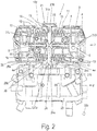
- FIG. 1 shows a schematic sectional view of a first embodiment of an inventive arrangement.
- the arrangement 1 is a test and connection device arrangement and comprises a test device 2 and a connection device 3.
- the test device 2 is provided for insertion into the connection device 3 and serves for testing and measuring electrical values of electrical devices connected to the connection device 3, which will not be described in detail.
- the test apparatus 2 has a scholarvoriquessgephase 23 and is not shown in detail. In the housing not described further plug-in and switching devices for testing and / or measuring purposes are arranged. At the bottom of the test device 2 pin elements 24 are mounted, of which only one example is shown here by way of example for all others. With these pin elements 24 and possibly other plugs, which will not be discussed further, the test device 2 is inserted into the connection device 3.
- the connecting device 3 is provided for mounting on a mounting rail 25 and fixed with its underside on this in the longitudinal direction 333 of the connecting device 3, for example, as shown here by means of holders 4b.
- the holders 4b will be described further below.
- the test device 2 is shown inserted from the top of the connection device 3 forth in the connection device 3.
- the connecting device 3 has in this embodiment (see FIG. 4 and 5 ) seven juxtaposed terminal or connection units 300, of which in FIG. 1 and 2 one with its housing 4 is representative of the other shown in section.
- the connection units 300 are each used to connect electrical lines that are substantially perpendicular to the longitudinal axis of the connection device 3 (which in FIG. 1 and 2 perpendicular to the plane of the drawing) can be inserted on both sides into the connection units 300 and can be fastened in clamping units 5 and 7.
- the clamping units 5 and 7 are shown in this embodiment as a pair, of course, larger pairs are possible.
- the clamping units 5 and 7 are provided here with screws, which can be reached by a respective operating portion 9, 10 from the top of the connecting device 3 ago.
- the clamping unit 5 is connected to a bus bar 6, wherein the opposite clamping unit 7 is mirror-inverted connected to a busbar 8.
- the busbars 6 and 8 lie in one plane and are electrically isolated from each other in a separating element 22 received.
- a first chamber 11 for receiving a first compression spring 15 is arranged in the housing 4.
- a further first chamber 12 for receiving a further first compression spring 16 is formed at the same height.
- Each first compression spring 15, 16 cooperates with a first contact lug 15a, 16a (see FIG. 3 ), which are arranged between the first compression spring 15, 16.
- the inserted pin member 24 of the test apparatus 2 which will be discussed in more detail below. Without inserted pin element 24, ie without inserted test device 2, the two first compression springs 15 and 16 press the first contact lugs 15a, 16a against each other ( FIG. 3 ) and establish between them an electrically conductive contact, which is inserted with the test device 2 (as in FIG. 1 shown) is interrupted by the pin member 24.
- the pin member 24 is attached to or integrally formed with a connection 24a on the underside of the tester housing 23. It is representative of more.
- the connection 24a is followed by a pin body 24b with a pin tip 24c.
- the pin member 24 of the test apparatus 2 is defined by a first opening 19a of a first opening portion 19 of the housing 4 of the terminal device 3 inserted through between the first compression springs 15 and 16.
- the first opening portion 19 is located at the top of the housing 4 of the connecting device 3.
- the pen tip 24c is used during insertion for threading and pressing apart the first contact lugs 15a and 16a of the first compression springs 15 and 16 and is received in the inserted state in the separating element 22, which for this purpose has a receptacle which corresponds to the pen tip 24c.
- the first contact lugs 15a and 16a are pressed by the first compression springs 15 and 16 with their contact sections separated by the pin element 24 against the pin body 24b, which in a preferred embodiment is designed to be electrically insulating.
- the pin body 24b When inserting the pin body 24b between the contact lugs 15a, 16a, the pin body 24b therefore separates the electrical connection between the contact lugs 15a, 16a.
- electrically conductive contact plates are arranged on the pin body 24b and each on the side facing the contact lugs 15a, 16a, which tap a respective voltage applied to the contact lugs 15a, 16a, so that a circuit flowing over the contact lugs 15a, 16a although it is interrupted.
- the contact plates can be connected to different measuring meters (not shown), so that, for example, the voltage applied to the contact lugs 15a, 16a, the current flowing via the contact lugs 15a, 16a, a frequency, a power, a Resistance or similar are measurable.
- the first compression springs 15 and 16 are inserted in the first chambers 11 and 12 under bias, so that a certain contact pressure of the first contact lugs 15a and 16a is present during their contacting.
- a second chamber 13 is arranged with a second compression spring 17 below the busbar 6 in the housing 4.
- a further second chamber 14 for receiving a further second compression spring 18 is formed at the same height.
- the second compression springs 17 and 18 are associated with the first compression springs 15 and 16 second contact lugs 17 a and 18 a (see FIG. 3 and 7 ).
- the second compression springs 17 and 18 are electrically connected in parallel with the first compression springs 15, 16. So that when plugged test device 2 and an electrical contact of the second contact lugs 17a and 18a of the second compression springs 17, 18 is interrupted, between the contact portions of the second contact lugs 17a and 18a of the second compression springs 17, 18, a plug element 21 is inserted.
- the second compression springs 17 and 18 are used in the second chambers 13 and 14 under bias to produce a certain contact pressure in the contacting of the second contact lugs 17 a and 18 a.
- the plug-in element 21 is formed like a nail, has a head 21a and an adjoining shaft 21b with a tip 21c. It is shown as representative of others and inserted through a second opening 20a of a second opening portion 20 of the housing 4 on the underside thereof between the second compression springs 17 and 18.
- the tip 21c is used during insertion for threading and pushing apart of the second contact lugs 17a and 18a of the second compression springs 17 and 18 and is included in the inserted state in the separator 22, which analogous to the pen tip 24c of the pin member 24 has a receptacle that with the top 21c corresponds.
- the second compression springs 17 and 18 rest with their contact sections separated by the plug-in element 21 on the shaft 21b, which is designed to be electrically insulating.
- the plug-in element 21 In order to lock the plug-in element 21 inextricably or only with difficulty releasably in the connection device 3, it has a latching means 21d which is latched with a counter latching means, which here is the housing 4 of the connection device 3.
- the latching element is designed here as a snap tab, which is integrally formed on the plug-in element 21.
- the plug-in element 21 is covered with mounted connection device 3 of the support rail 25 and therefore arranged inaccessible.
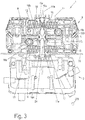
- the connecting device 3 is not only suitable for use on mounting rails 25, but also for other types of mounting, as in FIG. 2 in a schematic sectional view of a second embodiment of the inventive arrangement 1 is shown.
- connection device 3 is in this case attached with its underside on one side to a wall element 26 with wall openings 26a and wall cutouts 26b.
- the supports 4a of the housing 4 pass through the wall openings 26a, wherein the second opening portion 20 of the housing 4 on its underside protrudes through the wall cutout 26b.
- the test device 2 is arranged on the other side of the wall element 26, wherein its pin element 24 through the second opening 20 a of the second opening portion 20 between the second contact lugs 17a and 18a of the second compression springs 17 and 18 of the second chambers 13 and 14 is inserted.
- the test device 2 is thus inserted on the underside of the connection device 3 in this.
- the supports 4a of the connection device 3 rest on the underside of the test device 2, so that the test device 2 and the connection device 3 are defined spaced from each other.
- the plug-in element 21 is inserted in this second embodiment from the top of the connection device 3 through the first opening portion 19 between the first contact lugs 15a and 16a of the first compression springs 15 and 16 for the separation thereof.
- connection device 3 can be plugged together on both sides with the test device 2.
- connection device 3 is provided for mounting rail mounting, it is equipped with the plug-in elements 21 from the bottom.
- the plug-in elements 21 are inserted from the top of the connection device 3.
- FIG. 3 shows a schematic sectional view of the second embodiment according to FIG. 2 with first and second contact lugs 15a, 16a, 17a, 18a.
- the first and second contact lugs 15a, 16a and 17a, 18a face each other as pairs between the first compression springs 15 and 16 and the second compression springs 17, 18.
- the second contact lugs 15a and 16a contact, since no plug-in element 21 is inserted yet.
- the first and second contact lugs 15a, 16a and 17a, 18a have spring portions 15b, 16b, 17b, 18b, with which they are each electrically fixed to the busbars 6 and 8. Therefore, in each case the mirror image of the busbars 6, 8 opposite each other contact lugs 15a, 17a and 16a, 18a by the busbars 6, 8 connected electrically contacting each other.
- the contact lugs 15a and 17a are connected to the bus bar 6, and the contact lugs 16a and 18a are connected to the bus bar 8.
- FIG. 3 the upper, first contact lugs 15a and 16a are shown without plug-in element 21, wherein the lower, second contact lugs 17a and 18a are pushed apart by the pin element 24.
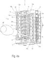
- FIG. 4 shows a schematic perspective view of an embodiment of a connecting device 3 according to the invention with a tamper-evident in a first position and FIG. 5 shows this manipulation protection in a second position.
- connection device 3 in this exemplary embodiment has seven clamping or connection units 300 arranged next to one another.
- first opening sections 19 with the first openings 19a can be seen.
- the first compression springs 15, 16 are arranged cooperatively with contact lugs 15a, 16a, of which only the contact lugs 16a cooperating with the first compression springs 16 can be seen.
- elongated protective elements 27 are arranged on both longitudinal sides on the clamping units 5, 7 (which are not visible), which are held longitudinally displaceable in guides 4c of the housing 4 in the longitudinal direction of the connecting device 3.
- the protective elements 27 are arranged in opposite directions.
- the protective elements 27 are in the first, closed position, i. the operating portions 9 and 10 of the clamping units 5, 7 are located below the protective elements 27 and are not accessible.
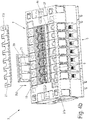
- the protective elements 27 have per clamping unit 5, 7 in each case a cover panel 27c with a cover opening 27d. So that the operating sections 9 and 10 of the clamping units can be made accessible, the protective elements 27 are displaceable in the direction of the arrows in opposite directions by means of a tool 28 via their actuating parts 27a in the second position.
- the clamping units 5, 7 are formed here as drawbar connections (s. Fig. 1 ).
- the invention is not limited to this training.
- the clamping units 5, 7 can also be designed with a different connection technology, for example as Switzerlandfederan forget.
- the connecting device 3 offers the possibility of electrically connecting a plurality of clamping units 5, 7 via transverse connectors 70.
- the cross connectors 70 like the Fig. 4 (b) shows, inserted during the assembly process below the protective elements 27 in the operating sections 9, 10 in a plug-in direction 700, so that in each case a plug contact 71 of the cross connector 70 engages in an operating section 9, 10 and the cross connector 70, the operating sections 9, 10, in which the Plug contacts 71 are inserted, electrically connected to each other.
- the protective element 27 is inserted after insertion of the cross connector 70 in the guides 4c, so that the cross connector 70 is inaccessible in the delivery state of the connecting device 3.
- the protective elements 27 are shifted so that the cover openings 27d of the cover panels 27c on the operating sections 9 and 10 of the clamping units 5, 7 are arranged and access to the clamping units 5, 7, for example with the tool (screwdriver) is possible.
- the actuating parts 27a of the protective elements 27 are arranged at a distance from the stops 4d of the housing 4.
- FIG. 6 shows a schematic perspective view of an embodiment of the connecting device 3 according to the invention in mounting rail mounting from below.
- double holders 4b are respectively inserted or latched into the housing 4 in four corner regions on the underside of the housing 4 of the connection device 3.
- Each holder 4b has an inwardly to the support rail 25 facing end with a support rail holding portion 4e in the form of a nose.
- the holders 4b are formed with arm-shaped wall holding portions 4f.
- connection device 3 is held by means of the support rail holding portion 4e of the holder 4b on the support rail 25 by the support rail holding portion 4e engage over a portion of the support rail 25.
- the holders 4b can be inserted or latched into the corresponding recesses of the housing 4 in the position shown, for example after the connecting device 3 has been applied, or pushed towards one another in the direction of the mounting rail 25 in order to create the overlapping of the mounting rail holding section 4e.
- the connection device 3 can also be pushed onto the support rail 25 in the longitudinal direction of the latter. Other options are of course conceivable.
- the holders 4b have a further holding function by means of the wall holding sections 4f, which in FIG. 7 is shown.
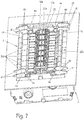
- FIG. 7 shows a schematic perspective view of an embodiment of the connecting device 3 according to the invention in wall mounting from below.
- the connecting device 3 with its underside in a wall section 26b of the wall element 26 (see also FIG. 2 ) used.
- the outwardly facing wall holding portions 4f of the holder 4b engage over an edge of the wall section 26b of the wall element 26 and hold and fasten the connecting device 3 to the wall element 26.
- the holder 4b can be inserted, for example, in corresponding openings on the bottom of the housing 4 and be locked.
- FIG. 7 is the bottom of the connecting device 3 with the second opening portion 20 and the second openings 20a for insertion of the test apparatus 2 (see FIG. 2 ) clearly visible.
- the ends of the second contact lugs 17a and 18a can be seen.
- connection device 3 is mounted both on a mounting rail 25 and on a wall cutout 26b of a wall element 26.
- the compression springs 15, 16 and 17, 18 are provided at their contact points with contact portions of special contact material or with the contact lugs 15 a, 16 a, 17 a, 18 a cooperate.
Landscapes
- Physics & Mathematics (AREA)
- General Physics & Mathematics (AREA)
- Connections Arranged To Contact A Plurality Of Conductors (AREA)
- Measuring Leads Or Probes (AREA)
- Details Of Connecting Devices For Male And Female Coupling (AREA)
- Testing Electric Properties And Detecting Electric Faults (AREA)
- Tests Of Electronic Circuits (AREA)
- Coupling Device And Connection With Printed Circuit (AREA)
- Connector Housings Or Holding Contact Members (AREA)
Description
- Die Erfindung betrifft eine Prüf- und Anschlussvorrichtungsanordnung nach dem Oberbegriff des Anspruchs 1.
- Eine derartige Anordnung beinhaltet eine Anschlussvorrichtung zum Anschluss von elektrischen Leitern und eine Prüfvorrichtung, welche mit der Anschlussvorrichtung verbindbar ist, um elektrische Größen, die mit den angeschlossenen elektrischen Leitern und damit verbundenen elektrischen Geräten in Zusammenhang stehen, zu prüfen und zu messen. Dabei werden Mess- und Prüfvorgänge ohne Veränderung der bestehenden Stromkreise vorgenommen. Zum Stand der Technik wird auf die
DE 10 2006 052 894 A1 verweisen, die eine gattungsgemäße Anordnung zeigt. - Ein kontinuierlich steigender Bedarf für derartige Anordnungen, z.B. in Automatisierungsbereichen, ergibt die Forderung nach verbesserten Funktionsgruppen sowie vergrößertem Einsatzbereich.
- Die Aufgabe der Erfindung ist es daher, eine verbesserte Anordnung bereitzustellen.
- Diese Aufgabe wird durch eine Prüf- und Anschlussvorrichtungsanordnung mit den Merkmalen des Anspruchs 1 gelöst.
- Die Anordnung ermöglicht die Vorteile von Mess- und Prüfvorgängen außerhalb des Produkts, in welches die Anschlussvorrichtung eingebunden ist bei gleichzeitiger Erhöhung von Anschlussmöglichkeiten der Prüfvorrichtung.
- Bei einer erfindungsgemäßen Prüf- und Anschlussvorrichtungsanordnung, mit einer Prüfvorrichtung, und mit einer Anschlussvorrichtung zum Anschluss von elektrischen Leitern, bei der die Prüfvorrichtung in die Anschlussvorrichtung einsteckbar ist und dabei eine elektrische Verbindung zwischen zwei sich elektrisch kontaktierenden Kontaktfahnen trennt, ist die Prüfvorrichtung von einer Oberseite der Anschlussvorrichtung und von einer Unterseite der Anschlussvorrichtung in die Anschlussvorrichtung einsteckbar. Und zwar ist erfindungsgemäß vorgesehen, dass die Prüfvorrichtung entweder von einer Oberseite der Anschlussvorrichtung oder von einer Unterseite der Anschlussvorrichtung in diese eingesteckt ist.
- Dadurch ist es möglich, die Anordnung vielseitiger einzusetzen.
- Erfindungsgemäß weist die Anschlussvorrichtung sowohl an ihrer Oberseite als auch an ihrer Unterseite zwei sich elektrisch kontaktierende Kontaktfahnen auf.
- Die zwei an der Oberseite angeordneten und die zwei an der Unterseite angeordneten Kontaktfahnen sind dabei bevorzugt übereinander angeordnet. Und zwar ist die Anschlussvorrichtung in Bezug auf die Kontaktfahnen vorzugsweise symmetrisch vorgesehen. Dies ermöglicht das Einstecken der Prüfvorrichtung sowohl von der Oberseite der Anschlussvorrichtung als auch von ihrer Unterseite, ohne dafür eine zusätzliche oder umständliche konstruktive Anpassung der Anschlussvorrichtung vornehmen zu müssen.
- Besonders bevorzugt sind die zwei an der Oberseite angeordneten und die zwei an der Unterseite angeordneten Kontaktfahnen elektrisch parallel geschaltet. Auch in elektrischer Hinsicht sind daher zum Einstecken und Anschließen der Prüfvorrichtung entweder von der Oberseite oder der Unterseite jeweils keine konstruktiven Anpassungen der Anschlussvorrichtung erforderlich. Zudem ist dies in einfacher Weise innerhalb der Anschlussvorrichtung möglich, wodurch diese in ihrem Volumen nicht vergrößert wird.
- Um ein fehlerhaftes Anschließen der Prüfvorrichtung, insbesondere ein Überbrücken der Prüfvorrichtung, zu vermeiden, ist ferner nach Anspruch 1 auch ein elektrisch isolierendes Steckelement bei der Anordnung vorgesehen. Es ist vorgesehen, dass das Steckelement bei von der Oberseite der Anschlussvorrichtung in diese eingesteckter Prüfvorrichtung die an der Unterseite der Anschlussvorrichtung angeordneten sich elektrisch kontaktierenden Kontaktfahnen elektrisch trennt, wobei das Steckelement bei von der Unterseite der Anschlussvorrichtung in diese eingesteckter Prüfvorrichtung die an der Oberseite der Anschlussvorrichtung angeordneten sich elektrisch kontaktierenden Kontaktfahnen elektrisch trennt. Dieses wieder entfernbare Steckelement ermöglicht es, die Anschlussvorrichtung je nach Position der Prüfvorrichtung an der Oberseite oder an der Unterseite der Anschlussvorrichtung durch Umstecken anzupassen, ohne weitere konstruktive Anpassungen zu erfordern.
- Es ist besonders bevorzugt, dass das Steckelement unlösbar in der Anschlussvorrichtung angeordnet ist. Prinzipiell ist aber auch eine Ausführungsform denkbar, bei der das Steckelement lösbar in die Anschlussvorrichtung eingesteckt ist. In dieser letztgenannten Ausführungsform ist es jedoch bevorzugt, dass es bei montierter Anschlussvorrichtung schwer zugänglich oder nur aufwendig aus der Anschlussvorrichtung lösbar ist.
- Zu diesem Zweck weist das Steckelement bevorzugt ein Verrastmittel auf, mit dem es im der Anschlussvorrichtung verrastbar ist. Die Anschlussvorrichtung weist dafür bevorzugt ein Gegenverrastmittel auf, welches in einer besonders bevorzugten Ausführungsform das Gehäuse der Anschlussvorrichtung ist. Beim Einstecken verrastet das Verrastmittel mit dem Gegenverrastmittel, so dass es entweder unlösbar oder nur schwer lösbar, beispielsweise durch Teildemontage der Anschlussvorrichtung oder zumindest mit zusätzlichem Werkzeug, in der Anschlussvorrichtung verrastet ist.
- In einer noch weiteren Ausführung weist die Anschlussvorrichtung mindestens ein Schutzelement auf, welches aus einer ersten Stellung, in welcher es Betätigungsabschnitte für darunter angeordnete Klemmeinheiten der Anschlussvorrichtung verschließt, in eine zweite Stellung verstellbar ist, in welcher die Betätigungsabschnitte zugänglich sind, bringbar ist. Damit ist ein einfacher und schneller Manipulationsschutz ermöglicht.
- In einer weiteren Ausführung ist das mindestens eine Schutzelement in einer Führung eines Gehäuses der Anschlussvorrichtung in Längsrichtung der Anschlussvorrichtung verschiebbar gehalten. Eine solche Ausgestaltung ist einfach und dabei kann das Schutzelement leicht und schnell verstellt werden.
- Es ist dabei vorgesehen, dass das mindestens eine Schutzelement jeweils ein Abdeckfeld mit einer Abdecköffnung pro Klemmeinheit aufweist. Auf diese Weise kann ein Schutzelement für eine bestimmte Anzahl von Klemmeinheiten durch einfaches Ablängen angepasst werden.
- In einer noch weiteren Ausführung ist die Anschlussvorrichtung für eine Tragschienenmontage und/oder eine Wandmontage vorgesehen. Dadurch wird ein vielseitiger Einsatzbereich geschaffen.
- In einer weiteren Ausführung weist die Anschlussvorrichtung der Prüf- und Anschlussvorrichtungsanordnung mindestens zwei anbringbare Halter auf, welche jeweils Tragschienenhalteabschnitte für eine Tragschienenmontage der Anschlussvorrichtung und Wandhalteabschnitte für eine Wandmontage der Anschlussvorrichtung aufweisen.
- Die anbringbaren Halter können z.B. in die Unterseite des Gehäuses der Anschlussvorrichtung in dafür vorgesehene Aufnahmen oder Ausnehmungen eingesteckt und verrastet werden, um die Anschlussvorrichtung sowohl an einer Tragschiene als auch an einem Wandelement festzulegen. Dadurch ist eine vielseitige Montagemöglichkeit mit gleichen Haltern geschaffen.
- In einer alternativen nicht erfindungsgemäßen Ausführung kann die Anschlussvorrichtung, welche zum Anschluss von elektrischen Leitern ausgebildet ist mindestens zwei anbringbare Halter umfassen, welche jeweils Tragschienenhalteabschnitte für eine Tragschienenmontage der Anschlussvorrichtung und Wandhalteabschnitte für eine Wandmontage der Anschlussvorrichtung aufweisen.
- Eine noch weitere nicht erfindungsgemäße Ausführung sieht vor, dass die Anschlussvorrichtung zum beidseitigen Einstecken einer Prüfvorrichtung von einer Oberseite der Anschlussvorrichtung und einer Unterseite der Anschlussvorrichtung mit ersten und zweiten Kontaktfahnen ausgebildet ist.
- Eine Anschlussvorrichtung, welche zum Anschluss von elektrischen Leitern ausgebildet ist, ist zum beidseitigen Einstecken einer Prüfvorrichtung von einer Oberseite der Anschlussvorrichtung und einer Unterseite der Anschlussvorrichtung mit ersten und zweiten Druckfedern ausgebildet.
- Anhand einer beispielhaften Ausführung wird die Erfindung mit Bezug auf die beigefügten Zeichnungen näher erläutert. Hierbei zeigen:
- Figur 1
- eine schematische Schnittansicht eines ersten Ausführungsbeispiels einer erfindungsgemäßen Anordnung mit an einer Tragschiene angeordneter Anschlussvorrichtung;
- Figur 2
- eine schematische Schnittansicht eines zweiten Ausführungsbeispiels der erfindungsgemäßen Anordnung mit an einem Wandelement angeordneter Anschlussvorrichtung;
- Figur 3
- eine schematische Schnittansicht eines weiteren Ausführungsbeispiels einer erfindungsgemäßen Anordnung mit analog der
Figur 2 an einem Wandelement angeordneter Anschlussvorrichtung, in der Kontaktfahnen sichtbar sind; - Figur 4
- in (a) eine schematische Perspektivansicht eines Ausführungsbeispiels einer erfindungsgemäßen Anschlussvorrichtung mit einem Manipulationsschutz in einer ersten Stellung, und in (b) eine schematische Perspektivansicht eines weiteren Ausführungsbeispiels einer erfindungsgemäßen Anschlussvorrichtung während eines Montagezustandes;
- Figur 5
- das Ausführungsbeispiel nach
Figur 4 mit dem Manipulationsschutz in einer zweiten Stellung; - Figur 6
- eine schematische Perspektivansicht eines Ausführungsbeispiels der erfindungsgemäßen Anschlussvorrichtung bei Tragschienenmontage von unten; und
- Figur 7
- eine schematische Perspektivansicht eines Ausführungsbeispiels der erfindungsgemäßen Anschlussvorrichtung bei Wandmontage von unten.
-
Figur 1 zeigt eine schematische Schnittansicht eines ersten Ausführungsbeispiels einer erfindungsgemäßen Anordnung 1. - Die Anordnung 1 ist eine Prüf- und Anschlussvorrichtungsanordnung und umfasst eine Prüfvorrichtung 2 und eine Anschlussvorrichtung 3.
- Die Prüfvorrichtung 2 ist zum Einstecken in die Anschlussvorrichtung 3 vorgesehen und dient zur Prüfung und Messung elektrischer Werte von an der Anschlussvorrichtung 3 angeschlossenen elektrischen Geräten, die nicht näher beschrieben werden sollen.
- Die Prüfvorrichtung 2 weist ein Prüfvorrichtungsgehäuse 23 auf und ist nicht näher dargestellt. In dem Gehäuse sind nicht weiter beschriebene Steck- und Schalteinrichtungen für Prüf- und/oder Messzwecke angeordnet. An der Unterseite der Prüfvorrichtung 2 sind Stiftelemente 24 angebracht, von denen hier beispielhaft stellvertretend für alle anderen nur eines gezeigt ist. Mit diesen Stiftelementen 24 und gegebenenfalls weiteren Steckern, auf die nicht weiter eingegangen werden soll, wird die Prüfvorrichtung 2 in die Anschlussvorrichtung 3 eingesteckt.
- In diesem ersten Ausführungsbeispiel ist die Anschlussvorrichtung 3 für die Montage auf einer Tragschiene 25 vorgesehen und mit ihrer Unterseite auf dieser in Längsrichtung 333 der Anschlussvorrichtung 3 befestigt, z.B. wie hier gezeigt mittels Halter 4b. Die Halter 4b werden weiter unten noch weiter beschrieben. Die Prüfvorrichtung 2 ist von der Oberseite der Anschlussvorrichtung 3 her in die Anschlussvorrichtung 3 eingesteckt gezeigt.
- Die Anschlussvorrichtung 3 weist in diesem Ausführungsbeispiel (siehe
Figur 4 und5 ) sieben nebeneinander angeordnete Klemm- bzw. Anschlusseinheiten 300 auf, von denen inFigur 1 und2 eine mit ihrem Gehäuse 4 stellvertretend für die anderen im Schnitt gezeigt ist. Die Anschlusseinheiten 300 dienen jeweils zum Anschluss elektrischer Leitungen, die im Wesentlichen rechtwinklig zur Längsachse der Anschlussvorrichtung 3 (welche inFigur 1 und2 senkrecht auf der Zeichnungsebene steht) beidseitig in die Anschlusseinheiten 300 einführbar und in Klemmeinheiten 5 und 7 befestigbar sind. Die Klemmeinheiten 5 und 7 sind in diesem Ausführungsbeispiel als ein Paar gezeigt, selbstverständlich sind auch größere Paarzahlen möglich. Die Klemmeinheiten 5 und 7 sind hier mit Schrauben versehen, welche durch einen jeweiligen Betätigungsabschnitt 9, 10 von der Oberseite der Anschlussvorrichtung 3 her erreichbar sind. Die Klemmeinheit 5 ist mit einer Stromschiene 6 verbunden, wobei die gegenüberliegende Klemmeinheit 7 spiegelbildlich mit einer Stromschiene 8 verbunden ist. Die Stromschienen 6 und 8 liegen in einer Ebene und sind elektrisch voneinander isoliert in einem Trennelement 22 aufgenommen. - Oberhalb der Stromschiene 6 ist in dem Gehäuse 4 eine erste Kammer 11 zur Aufnahme einer ersten Druckfeder 15 angeordnet. Auf der linken Seite ist auf gleicher Höhe eine weitere erste Kammer 12 zur Aufnahme einer weiteren ersten Druckfeder 16 eingeformt. Jede erste Druckfeder 15, 16 wirkt mit einer ersten Kontaktfahne 15a, 16a zusammen (siehe
Figur 3 ), welche zwischen den ersten Druckfeder 15, 16 angeordnet sind. In derFigur 1 befindet sich zwischen den ersten Kontaktfahnen 15a, 16a (die hier nicht zu sehen sind, sieheFigur 3 ) und den Druckfedern das eingesteckte Stiftelement 24 der Prüfvorrichtung 2, auf welches unten noch näher eingegangen wird. Ohne eingestecktes Stiftelement 24, d.h. ohne eingesteckte Prüfvorrichtung 2, drücken die beiden ersten Druckfedern 15 und 16 die ersten Kontaktfahnen 15a, 16a gegeneinander (Figur 3 ) und stellen zwischen diesen einen elektrisch leitenden Kontakt her, der bei eingesteckter Prüfvorrichtung 2 (wie inFigur 1 gezeigt) durch das Stiftelement 24 unterbrochen ist. - Das Stiftelement 24 ist mit einer Verbindung 24a an der Unterseite des Prüfvorrichtungsgehäuses 23 angebracht oder mit diesem einstückig ausgebildet. Es steht stellvertretend für weitere. An die Verbindung 24a schließt sich ein Stiftkörper 24b mit einer Stiftspitze 24c an. Das Stiftelement 24 der Prüfvorrichtung 2 ist durch eine erste Öffnung 19a eines ersten Öffnungsabschnitts 19 des Gehäuses 4 der Anschlussvorrichtung 3 hindurch zwischen die ersten Druckfedern 15 und 16 gesteckt. Der erste Öffnungsabschnitt 19 befindet sich an der Oberseite des Gehäuses 4 der Anschlussvorrichtung 3. Die Stiftspitze 24c dient beim Einstecken zum Einfädeln und Auseinanderdrücken der ersten Kontaktfahnen 15a und 16a der ersten Druckfedern 15 und 16 und ist im eingesteckten Zustand in dem Trennelement 22 aufgenommen, welches dazu eine Aufnahme aufweist, die mit der Stiftspitze 24c korrespondiert. Im eingesteckten Zustand ruhen die ersten Kontaktfahnen 15a und 16a gedrückt durch die ersten Druckfedern 15 und 16 mit ihren durch das Stiftelement 24 getrennten Kontaktabschnitten an dem Stiftkörper 24b, welcher in einer bevorzugten Ausführungsform elektrisch isolierend ausgebildet ist. Beim Einstecken des Stiftkörper 24b zwischen die Kontaktfahnen 15a, 16a trennt der Stiftkörper 24b daher die elektrische Verbindung zwischen den Kontaktfahnen 15a, 16a. Besonders bevorzugt sind am Stiftkörper 24b aber jeweils an der den Kontaktfahnen 15a, 16a zugewandten Seite elektrisch leitende Kontaktplatten (nicht gezeigt) angeordnet, die eine jeweils an den Kontaktfahnen 15a, 16a anliegende Spannung abgreifen, so dass ein über die Kontaktfahnen 15a, 16a fließender Stromkreis zwar unterbrochen wird. In der oder über die Prüfvorrichtung 2 sind die Kontaktplatten jedoch mit verschiedenen Messmetern (nicht gezeigt) verbindbar, so dass beispielsweise die an den Kontaktfahnen 15a, 16a anliegende Spannung, der über die Kontaktfahnen 15a, 16a fließende Strom, eine Frequenz, eine Leistung, ein Widerstand oder ähnlich messbar sind.
- Die ersten Druckfedern 15 und 16 sind in den ersten Kammern 11 und 12 unter Vorspannung eingesetzt, sodass ein bestimmter Kontaktdruck der ersten Kontaktfahnen 15a und 16a bei ihrer Kontaktierung vorhanden ist.
- In gleicher Weise ist unterhalb der Stromschiene 6 in dem Gehäuse 4 eine zweite Kammer 13 mit einer zweiten Druckfeder 17 angeordnet. Auf der linken Seite ist auf gleicher Höhe eine weitere zweite Kammer 14 zur Aufnahme einer weiteren zweiten Druckfeder 18 eingeformt. Den zweiten Druckfedern 17 und 18 sind wie den ersten Druckfedern 15 und 16 zweite Kontaktfahnen 17a und 18a zugeordnet (siehe
Figur 3 und7 ). Die zweiten Druckfedern 17 und 18 sind elektrisch mit den ersten Druckfedern 15, 16 parallel geschaltet. Damit bei eingesteckter Prüfvorrichtung 2 auch ein elektrischer Kontakt der zweiten Kontaktfahnen 17a und 18a der zweiten Druckfedern 17, 18 untereinander unterbrochen wird, ist zwischen den Kontaktabschnitten der zweiten Kontaktfahnen 17a und 18a der zweiten Druckfedern 17, 18 ein Steckelement 21 eingesetzt. - Auch die zweiten Druckfedern 17 und 18 sind in den zweiten Kammern 13 und 14 unter Vorspannung eingesetzt, um einen bestimmten Kontaktdruck bei der Kontaktierung der zweiten Kontaktfahnen 17a und 18a zu erzeugen.
- Das Steckelement 21 ist nagelartig ausgebildet, weist einen Kopf 21a und einen sich daran anschließenden Schaft 21b mit einer Spitze 21c auf. Es ist stellvertretend für weitere gezeigt und durch eine zweite Öffnung 20a eines zweiten Öffnungsabschnitts 20 des Gehäuses 4 an dessen Unterseite hindurch zwischen die zweiten Druckfedern 17 und 18 gesteckt. Die Spitze 21c dient beim Einstecken zum Einfädeln und Auseinanderdrücken der zweiten Kontaktfahnen 17a und 18a der zweiten Druckfedern 17 und 18 und ist im eingesteckten Zustand in dem Trennelement 22 aufgenommen, welches dazu analog zur Stiftspitze 24c des Stiftelementes 24 eine Aufnahme aufweist, die mit der Spitze 21c korrespondiert. Im eingesteckten Zustand ruhen die zweiten Druckfedern 17 und 18 mit ihren durch das Steckelement 21 getrennten Kontaktabschnitten an dem Schaft 21b, welcher elektrisch isolierend ausgebildet ist.
- Um das Steckelement 21 unlösbar oder nur aufwendig lösbar in der Anschlussvorrichtung 3 zu verrasten, weist es ein Verrastmittel 21d auf, welches mit einem Gegenverrastmittel, welches hier das Gehäuse 4 der Anschlussvorrichtung 3 ist, verrastet. Das Verrastelement ist hier als Schnappzunge ausgebildet, die einstückig am Steckelement 21 angeformt ist. Zudem ist das Steckelement 21 bei montierter Anschlussvorrichtung 3 von der Tragschiene 25 überdeckt und daher unzugänglich angeordnet.
- Durch die ersten und zweiten Kammern 11, 12 und 13, 14 ist die Anschlussvorrichtung 3 nicht nur für die Verwendung zur Montage auf Tragschienen 25 geeignet, sondern auch für andere Montagearten, wie in
Figur 2 in einer schematische Schnittansicht eines zweiten Ausführungsbeispiels der erfindungsgemäßen Anordnung 1 dargestellt ist. - Die Anschlussvorrichtung 3 ist hierbei mit ihrer Unterseite auf einer Seite an einem Wandelement 26 mit Wandöffnungen 26a und Wandausschnitten 26b angebracht. Die Auflagen 4a des Gehäuses 4 treten durch die Wandöffnungen 26a hindurch, wobei der zweite Öffnungsabschnitt 20 des Gehäuses 4 an dessen Unterseite durch den Wandausschnitt 26b hervortritt.
- Die Prüfvorrichtung 2 ist auf der anderen Seite des Wandelementes 26 angeordnet, wobei ihr Stiftelement 24 durch die zweite Öffnung 20a des zweiten Öffnungsabschnitts 20 zwischen die zweiten Kontaktfahnen 17a und 18a der zweiten Druckfedern 17 und 18 der zweiten Kammern 13 und 14 eingesteckt ist. Die Prüfvorrichtung 2 ist somit auf der Unterseite der Anschlussvorrichtung 3 in diese eingesteckt. Dabei ruhen die Auflagen 4a der Anschlussvorrichtung 3 auf der Unterseite der Prüfvorrichtung 2, so dass die Prüfvorrichtung 2 und die Anschlussvorrichtung 3 definiert voneinander beabstandet sind.
- Das Steckelement 21 ist in diesem zweiten Ausführungsbeispiel von der Oberseite der Anschlussvorrichtung 3 durch den ersten Öffnungsabschnitt 19 zwischen die ersten Kontaktfahnen 15a und 16a der ersten Druckfedern 15 und 16 zur Trennung derselben eingesteckt.
- Die weiteren Funktionselemente und -gruppen sind bereits im Zusammenhang mit
Figur 1 beschrieben. - Somit kann die Anschlussvorrichtung 3 beidseitig mit der Prüfvorrichtung 2 zusammengesteckt werden.
- Ist die Anschlussvorrichtung 3 für Tragschienenmontage vorgesehen, wird sie mit den Steckelementen 21 von der Unterseite her bestückt. Bei z.B. einer Wandmontage, bei welcher die Anschlussvorrichtung 3 am besten von der Unterseite her zugänglich ist, werden die Steckelemente 21 von der Oberseite der Anschlussvorrichtung 3 eingesetzt.
-
Figur 3 zeigt eine schematische Schnittansicht des zweiten Ausführungsbeispiels nachFigur 2 mit ersten und zweiten Kontaktfahnen 15a, 16a, 17a, 18a. - Die ersten und zweiten Kontaktfahnen 15a, 16a und 17a, 18a stehen sich jeweils als Paare zwischen den ersten Druckfedern 15 und 16 und den zweiten Druckfedern 17, 18 gegenüber. Die zweiten Kontaktfahnen 15a und 16a kontaktieren sich, da noch kein Steckelement 21 eingesteckt ist. Die ersten und zweiten Kontaktfahnen 15a, 16a und 17a, 18a weisen Federabschnitte 15b, 16b, 17b, 18b auf, mit welchen sie jeweils auf den Stromschienen 6 und 8 elektrisch leitend befestigt sind. Daher sind jeweils die spiegelbildlich der Stromschienen 6, 8 einander gegenüber liegenden Kontaktfahnen 15a, 17a und 16a, 18a durch die Stromschienen 6, 8 elektrisch kontaktierend miteinander verbunden. Mit anderen Worten sind die Kontaktfahnen 15a und 17a mit der Stromschiene 6 verbunden, und die Kontaktfahnen 16a und 18a sind an die Stromschiene 8 angeschlossen.
- In der
Figur 3 sind die oberen, ersten Kontaktfahnen 15a und 16a ohne Steckelement 21 dargestellt, wobei die unteren, zweiten Kontaktfahnen 17a und 18a durch das Stiftelement 24 auseinandergedrückt sind. -
Figur 4 zeigt eine schematische Perspektivansicht eines Ausführungsbeispiels einer erfindungsgemäßen Anschlussvorrichtung 3 mit einem Manipulationsschutz in einer ersten Stellung undFigur 5 zeigt diesen Manipulationsschutz in einer zweiten Stellung. - Wie bereits oben beschrieben weist die Anschlussvorrichtung 3 in diesem Ausführungsbeispiel sieben nebeneinander angeordnete Klemm- bzw. Anschlusseinheiten 300 auf. In den
Figuren 4 und5 sind die ersten Öffnungsabschnitte 19 mit den ersten Öffnungen 19a zu erkennen. In dieser Ausführung sind die ersten Druckfedern 15, 16 mit Kontaktfahnen 15a, 16a zusammenwirkend angeordnet, von denen nur die mit den ersten Druckfedern 16 zusammenwirkenden Kontaktfahnen 16a zu sehen sind. - In dem Gehäuse 4 der Anschlussvorrichtung 3 sind auf beiden Längsseiten über den Klemmeinheiten 5, 7 (die nicht sichtbar sind), längliche Schutzelemente 27 angeordnet, die in Führungen 4c des Gehäuses 4 in Längsrichtung der Anschlussvorrichtung 3 längsverschiebbar gehalten sind. Die Schutzelemente 27 sind gegenläufig angeordnet. Die Schutzelemente 27 befinden sich in der ersten, geschlossenen Stellung, d.h. die Betätigungsabschnitte 9 und 10 der Klemmeinheiten 5, 7 befinden sich unterhalb der Schutzelemente 27 und sind nicht zugänglich.
- In der geschlossenen Stellung liegen die Betätigungsteile 27a der Schutzelemente 27 mit einer Kante an einem Anschlag 4d des Gehäuses 4 an.
- Die Schutzelemente 27 weisen pro Klemmeinheit 5, 7 jeweils ein Abdeckfeld 27c mit einer Abdecköffnung 27d auf. Damit die Betätigungsabschnitte 9 und 10 der Klemmeinheiten zugänglich gemacht werden können, sind die Schutzelemente 27 in den Pfeilrichtungen gegenläufig mittels eines Werkzeugs 28 über ihre Betätigungsteile 27a in die zweite Stellung verschiebbar.
- Die Klemmeinheiten 5, 7 sind hier als Zugbügelanschlüsse ausgebildet (s.
Fig. 1 ). Die Erfindung ist aber nicht auf diese Ausbildung beschränkt. Sondern die Klemmeinheiten 5, 7 können auch mit einer anderen Anschlusstechnik ausgeführt sein, beispielsweise als Zugfederanschlüsse. - Optional bietet die erfindungsgemäße Anschlussvorrichtung 3 die Möglichkeit, mehrere Klemmeinheiten 5, 7 über Querverbinder 70 miteinander elektrisch zu verbinden. Die Querverbinder 70 werden, wie die
Fig. 4(b) zeigt, während des Montageprozesses unterhalb der Schutzelemente 27 in die Betätigungsabschnitte 9, 10 in eine Einsteckrichtung 700 eingesteckt, so dass jeweils ein Steckkontakt 71 des Querverbinders 70 in einen Betätigungsabschnitt 9, 10 eingreift und der Querverbinder 70 die Betätigungsabschnitte 9, 10, in die die Steckkontakte 71 eingesteckt sind, elektrisch miteinander verbindet. Das Schutzelement 27 wird nach dem Einstecken des Querverbinders 70 in die Führungen 4c eingeschoben, so dass der Querverbinder 70 im Auslieferungszustand der Anschlussvorrichtung 3 unzugänglich ist. - In der in
Figur 5 gezeigten zweiten Stellung sind die Schutzelemente 27 so verschoben, dass die Abdecköffnungen 27d der Abdeckfelder 27c über den Betätigungsabschnitten 9 und 10 der Klemmeinheiten 5, 7 angeordnet sind und ein Zugriff auf die Klemmeinheiten 5, 7 z.B. mit dem Werkzeug (Schraubendreher) möglich ist. Dabei sind die Betätigungsteile 27a der Schutzelemente 27 in einem Abstand von den Anschlägen 4d des Gehäuses 4 angeordnet. -
Figur 6 zeigt eine schematische Perspektivansicht eines Ausführungsbeispiels der erfindungsgemäßen Anschlussvorrichtung 3 bei Tragschienenmontage von unten. - In diesem Ausführungsbeispiel sind in vier Eckbereichen an der Unterseite des Gehäuses 4 der Anschlussvorrichtung 3 jeweils doppelte Halter 4b in das Gehäuse 4 eingesteckt bzw. eingerastet. Jeder Halter 4b weist ein nach innen zur Tragschiene 25 weisendes Ende mit einem Tragschienenhalteabschnitt 4e in Form einer Nase auf. An den anderen Enden, welche jeweils nach außen weisen, sind die Halter 4b mit armförmigen Wandhalteabschnitten 4f ausgebildet.
- Bei der in
Figur 6 gezeigten Montage der Anschlussvorrichtung 3 auf der Tragschiene 25 wird die Anschlussvorrichtung 3 mittels der Tragschienenhalteabschnitt 4e der Halter 4b an der Tragschiene 25 gehalten, indem die Tragschienenhalteabschnitt 4e einen Abschnitt der Tragschiene 25 übergreifen. Dazu können die Halter 4b z.B. nach aufgebrachter Anschlussvorrichtung 3 in diese in entsprechende Ausnehmungen des Gehäuses 4 in die gezeigte Position eingesteckt bzw. eingerastet werden oder in Richtung Tragschiene 25 aufeinander zu geschoben werden, um das Übergreifen der Tragschienenhalteabschnitt 4e zu schaffen. Die Anschlussvorrichtung 3 kann aber auch in Längsrichtung der Tragschiene 25 auf diese aufgeschoben werden. Andere Möglichkeiten sind natürlich denkbar. - Die Halter 4b weisen mittels der Wandhalteabschnitten 4f eine weitere Haltefunktion auf, die in
Figur 7 dargestellt ist. -
Figur 7 zeigt eine schematische Perspektivansicht eines Ausführungsbeispiels der erfindungsgemäßen Anschlussvorrichtung 3 bei Wandmontage von unten. - In diesem Ausführungsbeispiel ist die Anschlussvorrichtung 3 mit ihrer Unterseite in einen Wandausschnitt 26b des Wandelementes 26 (siehe auch
Figur 2 ) eingesetzt. Die nach außen weisenden Wandhalteabschnitte 4f der Halter 4b übergreifen hier einen Rand des Wandausschnitts 26b des Wandelementes 26 und halten und befestigen so die Anschlussvorrichtung 3 an dem Wandelement 26. Zur Montage können die Halter 4b beispielsweise in entsprechende Öffnungen an der Unterseite des Gehäuses 4 eingesteckt und verrastet werden. - In
Figur 7 ist die Unterseite der Anschlussvorrichtung 3 mit dem zweiten Öffnungsabschnitt 20 und den zweiten Öffnungen 20a zum Einstecken der Prüfvorrichtung 2 (sieheFigur 2 ) deutlich zu erkennen. Außerdem sind die Enden der zweiten Kontaktfahnen 17a und 18a zu sehen. - Die Halter 4b ermöglichen somit eine Montage der Anschlussvorrichtung 3 sowohl auf einer Tragschiene 25 als auch an einem Wandausschnitt 26b eines Wandelementes 26.
- Durch das beschriebene Ausführungsbeispiel wird die Erfindung nicht eingeschränkt. Sie ist im Rahmen der angefügten Ansprüche natürlich modifizierbar.
- Es ist denkbar, dass die Druckfedern 15, 16 und 17, 18 an ihren Kontaktstellen mit Kontaktabschnitten aus speziellem Kontaktmaterial versehen sind oder mit den Kontaktfahnen 15a, 16a, 17a, 18a zusammenwirken.
-
- 1
- Anordnung
- 2
- Prüfvorrichtung
- 3
- Anschlussvorrichtung
- 333
- Längsrichtung / Längserstreckung der Anschlussvorrichtung
- 300
- Anschlusseinheit
- 4
- Gehäuse
- 4a
- Fuß
- 4b
- Halter
- 4c
- Führung
- 4d
- Anschlag
- 4e
- Tragschienenhalteabschnitt
- 4f
- Wandhalteabschnitt
- 5,7
- Klemmeinheit
- 6,8
- Stromschiene
- 9, 10
- Betätigungsabschnitt
- 11, 12
- Erste Kammern
- 13, 14
- Zweite Kammer
- 15, 16
- Erste Druckfeder
- 15a, 16a
- Erste Kontaktfahne
- 15b, 16b
- Federabschnitt
- 17, 18
- Zweite Druckfeder
- 17a, 18a
- Zweite Kontaktfahne
- 17b, 18b
- Federabschnitt
- 19
- Erster Öffnungsabschnitt
- 19a
- Erste Öffnung
- 20
- Zweiter Öffnungsabschnitt
- 20a
- Zweite Öffnung
- 21
- Steckelement
- 21a
- Kopf
- 21b
- Schaft
- 21c
- Spitze
- 22
- Trennelement
- 23
- Prüfvorrichtungsgehäuse
- 24
- Stiftelement
- 24a
- Verbindung
- 24b
- Stiftkörper
- 24c
- Stiftspitze
- 25
- Tragschiene
- 26
- Wandelement
- 26a
- Wandöffnung
- 26b
- Wandausschnitt
- 27
- Schutzelement
- 27a
- Betätigungsteil
- 27b
- Ausnehmung
- 27c
- Abdeckfeld
- 27d
- Abdecköffnung
- 28
- Werkzeug
- 70
- Querverbinder
- 71
- Steckkontakt
- 700
- Einsteckrichtung
Claims (9)
- Prüf- und Anschlussvorrichtungsanordnung (1), mit
einer Prüfvorrichtung (2); und
einer Anschlussvorrichtung (3) zum Anschluss von elektrischen Leitern,
wobei die Prüfvorrichtung (2) in die Anschlussvorrichtung (3) einsteckbar ist und dabei eine elektrische Verbindung zwischen zwei sich elektrisch kontaktierenden Kontaktfahnen (15a, 16a, 17a, 18a) trennt,
dadurch gekennzeichnet,
dass die Prüfvorrichtung (2) entweder von einer Oberseite der Anschlussvorrichtung (3) oder von einer Unterseite der Anschlussvorrichtung (3) in die Anschlussvorrichtung (3) eingesteckt ist, wobei die Anschlussvorrichtung (3) sowohl an ihrer Oberseite als auch an ihrer Unterseite zwei sich elektrisch kontaktierende Kontaktfahnen (15a, 16a, 17a, 18a) aufweist und dass ein elektrisch isolierendes Steckelement (21) vorgesehen ist, das bei von der Oberseite der Anschlussvorrichtung (3) in diese eingesteckter Prüfvorrichtung (2) die an der Unterseite der Anschlussvorrichtung angeordneten sich elektrisch kontaktierenden Kontaktfahnen (15a, 16a, 17a, 18a) elektrisch trennt, und dass das Steckelement (21) bei von der Unterseite der Anschlussvorrichtung (3) in diese eingesteckter Prüfvorrichtung (2) die an der Oberseite der Anschlussvorrichtung (3) angeordneten sich elektrisch kontaktierenden Kontaktfahnen (15a, 16a, 17a, 18a) elektrisch trennt. - Prüf- und Anschlussvorrichtungsanordnung nach Anspruch 1, dadurch gekennzeichnet, dass die zwei an der Oberseite angeordneten und die zwei an der Unterseite angeordneten Kontaktfahnen (15a, 16a, 17a, 18a) übereinander angeordnet sind.
- Prüf- und Anschlussvorrichtungsanordnung nach Anspruch 2, dadurch gekennzeichnet, dass die zwei an der Oberseite angeordneten und die zwei an der Unterseite angeordneten Kontaktfahnen (15a, 16a, 17a, 18a) elektrisch parallel geschaltet sind.
- Prüf- und Anschlussvorrichtungsanordnung nach einem der vorherigen Ansprüche, dadurch gekennzeichnet, dass das Steckelement (21) unlösbar in die Anschlussvorrichtung (3) eingesteckt ist.
- Prüf- und Anschlussvorrichtungsanordnung nach einem der vorhergehenden Ansprüche, dadurch gekennzeichnet, dass die Anschlussvorrichtung (3) mindestens ein Schutzelement (27) aufweist, welches aus einer ersten Stellung, in welcher es Betätigungsabschnitte (9, 10) für darunter angeordnete Klemmeinheiten (5, 7) der Anschlussvorrichtung (3) verschließt, in eine zweite Stellung verstellbar ist, in welcher die Betätigungsabschnitte (9, 10) zugänglich sind.
- Prüf- und Anschlussvorrichtungsanordnung nach Anspruch 5, dadurch gekennzeichnet, dass das mindestens eine Schutzelement (27) in einer Führung (4a) eines Gehäuses (4) der Anschlussvorrichtung (3) in Längsrichtung der Anschlussvorrichtung (3) verschiebbar gehalten ist.
- Prüf- und Anschlussvorrichtungsanordnung nach Anspruch 5 oder 6, dadurch gekennzeichnet, dass das mindestens eine Schutzelement (27) jeweils ein Abdeckfeld (27c) mit einer Abdecköffnung (27d) pro Klemmeinheit (5, 7) aufweist.
- Prüf- und Anschlussvorrichtungsanordnung nach einem der vorhergehenden Ansprüche, dadurch gekennzeichnet, dass die Anschlussvorrichtung (3) für eine Tragschienenmontage und/oder eine Wandmontage vorgesehen ist.
- Prüf- und Anschlussvorrichtungsanordnung nach Anspruch 8, dadurch gekennzeichnet, dass die Anschlussvorrichtung (3) mindestens zwei anbringbare Halter (4b) aufweist, welche jeweils Tragschienenhalteabschnitte (4e) für die Tragschienenmontage der Anschlussvorrichtung (3) und Wandhalteabschnitte (4f) für die Wandmontage der Anschlussvorrichtung (3) aufweisen.
Applications Claiming Priority (2)
| Application Number | Priority Date | Filing Date | Title |
|---|---|---|---|
| DE202011101414 | 2011-06-03 | ||
| PCT/EP2012/059383 WO2012163713A1 (de) | 2011-06-03 | 2012-05-21 | Prüf- und anschlussvorrichtungsanordnung und anschlussvorrichtung |
Publications (2)
| Publication Number | Publication Date |
|---|---|
| EP2715871A1 EP2715871A1 (de) | 2014-04-09 |
| EP2715871B1 true EP2715871B1 (de) | 2019-10-09 |
Family
ID=46172779
Family Applications (2)
| Application Number | Title | Priority Date | Filing Date |
|---|---|---|---|
| EP12726599.9A Withdrawn EP2715872A1 (de) | 2011-06-03 | 2012-05-21 | Prüf- und anschlussvorrichtungsanordnung und prüfvorrichtung |
| EP12723855.8A Active EP2715871B1 (de) | 2011-06-03 | 2012-05-21 | Prüf- und anschlussvorrichtungsanordnung |
Family Applications Before (1)
| Application Number | Title | Priority Date | Filing Date |
|---|---|---|---|
| EP12726599.9A Withdrawn EP2715872A1 (de) | 2011-06-03 | 2012-05-21 | Prüf- und anschlussvorrichtungsanordnung und prüfvorrichtung |
Country Status (8)
| Country | Link |
|---|---|
| US (2) | US9081033B2 (de) |
| EP (2) | EP2715872A1 (de) |
| KR (2) | KR20140063562A (de) |
| CN (2) | CN103597666B (de) |
| BR (2) | BR112013030451A2 (de) |
| DE (5) | DE102012104350A1 (de) |
| RU (2) | RU2594899C2 (de) |
| WO (2) | WO2012163713A1 (de) |
Families Citing this family (9)
| Publication number | Priority date | Publication date | Assignee | Title |
|---|---|---|---|---|
| DE102012107264A1 (de) * | 2012-08-08 | 2014-02-13 | Phoenix Contact Gmbh & Co. Kg | Anschlussmodul |
| DE202012104617U1 (de) * | 2012-11-28 | 2014-03-03 | Weidmüller Interface GmbH & Co. KG | Montage einer Anschlussvorrichtung |
| DE102014103420A1 (de) | 2014-03-13 | 2015-09-17 | Weidmüller Interface GmbH & Co. KG | Sicherheitsprüfanordnung und Verfahren zu deren Betrieb |
| BE1026491B1 (de) * | 2018-07-27 | 2020-02-24 | Phoenix Contact Gmbh & Co | Prüfsteckerblock und Prüfklemmenblock |
| BE1026735B1 (de) * | 2018-10-30 | 2020-06-02 | Phoenix Contact Gmbh & Co | Elektrische Reihenklemme |
| CN110324002B (zh) * | 2019-07-15 | 2024-06-25 | 正泰新能科技股份有限公司 | 一种iv自动测试流水线 |
| BR202019016911Y1 (pt) * | 2019-08-14 | 2024-03-12 | Gridspertise Latam S.A | Bloco de conexão elétrica |
| DE102020101321B4 (de) * | 2020-01-21 | 2021-10-07 | Phoenix Contact Gmbh & Co. Kg | Baugruppe eines Elektronikgeräts mit einem Elektronikgehäuse und einer Grundleiste |
| CN114280402B (zh) * | 2021-12-23 | 2023-11-03 | 安徽建国电力有限公司 | 一种耐磨抗腐蚀的铜铝稀土接地合金性能检测装置及方法 |
Family Cites Families (8)
| Publication number | Priority date | Publication date | Assignee | Title |
|---|---|---|---|---|
| CH663493A5 (de) | 1984-06-08 | 1987-12-15 | Inventio Ag | Pruefsteckvorrichtung fuer eine klemmenleiste. |
| US4676568A (en) * | 1986-02-21 | 1987-06-30 | Adc Telecommunications, Inc. | Terminal test plug |
| DE19709054C1 (de) | 1997-03-06 | 1998-07-16 | Weidmueller Interface | Prüfstecker mit Betätigungswerkzeug |
| DE29917825U1 (de) * | 1999-10-09 | 2001-02-22 | Weidmüller Interface GmbH & Co, 32760 Detmold | Verbindungselement mit Querverbindung |
| DE102004040859B4 (de) | 2004-08-23 | 2007-03-15 | Phoenix Contact Gmbh & Co. Kg | Elektrische Reihenklemme und Prüfstecker zur Verwendung bei einer elektrischen Klemme |
| DE102006052894B4 (de) * | 2006-11-08 | 2013-05-16 | Phoenix Contact Gmbh & Co. Kg | Reihenklemme, Prüfstecker und Prüfklemmenblock |
| DE202010017964U1 (de) * | 2010-08-19 | 2013-05-02 | Phoenix Contact Gmbh & Co. Kg | Elektrische Anschlussklemme |
| CN201868657U (zh) * | 2010-10-14 | 2011-06-15 | 富士康(昆山)电脑接插件有限公司 | 电连接器 |
-
2012
- 2012-05-21 RU RU2013156841/07A patent/RU2594899C2/ru active
- 2012-05-21 DE DE201210104350 patent/DE102012104350A1/de active Pending
- 2012-05-21 KR KR20147000133A patent/KR20140063562A/ko not_active Application Discontinuation
- 2012-05-21 DE DE201220101849 patent/DE202012101849U1/de not_active Expired - Lifetime
- 2012-05-21 EP EP12726599.9A patent/EP2715872A1/de not_active Withdrawn
- 2012-05-21 BR BR112013030451A patent/BR112013030451A2/pt not_active Application Discontinuation
- 2012-05-21 CN CN201280027221.7A patent/CN103597666B/zh active Active
- 2012-05-21 WO PCT/EP2012/059383 patent/WO2012163713A1/de active Application Filing
- 2012-05-21 WO PCT/EP2012/059392 patent/WO2012163716A1/de active Application Filing
- 2012-05-21 KR KR1020147000134A patent/KR101925385B1/ko active IP Right Grant
- 2012-05-21 BR BR112013030460A patent/BR112013030460A2/pt not_active Application Discontinuation
- 2012-05-21 DE DE201210104351 patent/DE102012104351A1/de active Pending
- 2012-05-21 DE DE201210104339 patent/DE102012104339A1/de active Pending
- 2012-05-21 RU RU2013156846/07A patent/RU2599571C2/ru active
- 2012-05-21 EP EP12723855.8A patent/EP2715871B1/de active Active
- 2012-05-21 US US14/119,968 patent/US9081033B2/en active Active
- 2012-05-21 CN CN201280027223.6A patent/CN103582978B/zh active Active
- 2012-05-21 DE DE201220101845 patent/DE202012101845U1/de not_active Expired - Lifetime
- 2012-05-21 US US14/123,212 patent/US9075084B2/en active Active
Non-Patent Citations (1)
| Title |
|---|
| None * |
Also Published As
| Publication number | Publication date |
|---|---|
| KR20140063562A (ko) | 2014-05-27 |
| DE102012104339A1 (de) | 2012-12-06 |
| EP2715871A1 (de) | 2014-04-09 |
| DE202012101845U1 (de) | 2012-09-04 |
| US20140077832A1 (en) | 2014-03-20 |
| KR101925385B1 (ko) | 2019-02-27 |
| WO2012163716A1 (de) | 2012-12-06 |
| US20140097855A1 (en) | 2014-04-10 |
| DE202012101849U1 (de) | 2012-09-04 |
| BR112013030451A2 (pt) | 2016-09-27 |
| US9081033B2 (en) | 2015-07-14 |
| WO2012163713A1 (de) | 2012-12-06 |
| CN103597666B (zh) | 2016-06-29 |
| DE102012104351A1 (de) | 2012-12-06 |
| CN103597666A (zh) | 2014-02-19 |
| CN103582978A (zh) | 2014-02-12 |
| RU2594899C2 (ru) | 2016-08-20 |
| CN103582978B (zh) | 2016-03-09 |
| US9075084B2 (en) | 2015-07-07 |
| KR20140063563A (ko) | 2014-05-27 |
| RU2013156846A (ru) | 2015-07-20 |
| RU2599571C2 (ru) | 2016-10-10 |
| BR112013030460A2 (pt) | 2016-09-27 |
| RU2013156841A (ru) | 2015-07-20 |
| EP2715872A1 (de) | 2014-04-09 |
| DE102012104350A1 (de) | 2012-12-06 |
Similar Documents
| Publication | Publication Date | Title |
|---|---|---|
| EP2715871B1 (de) | Prüf- und anschlussvorrichtungsanordnung | |
| DE102005045596B3 (de) | Feder-Steckklemme | |
| EP1811604B1 (de) | Elektrischer Reihenklemmenblock | |
| EP2738884B1 (de) | Montage einer Anschlussvorrichtung | |
| DE102007053535B4 (de) | Verbindungsmodul und Einheit aus einem Schaltgerät, einem Verbindungsmodul und einem Adapter | |
| EP2839544B1 (de) | Prüfklemmenblock | |
| EP2255409A1 (de) | Schaltbrücke und baueinheit aus mindestens zwei elektrischen reihenklemmen und einer schaltbrücke | |
| EP2086077A2 (de) | Montagesystem für elektrische und/oder mechanische Komponenten | |
| EP1898436B1 (de) | Steckvorrichtung zum Stecken auf eine elektrische Schaltvorrichtung | |
| EP2622689B1 (de) | Querverbinder mit markierung | |
| AT517769B1 (de) | Energiezähler-Anschlussklemmenblock mit Überbrückungsvorrichtung | |
| EP3136513A1 (de) | Anschlussvorrichtung zum anschluss eines leiters an eine sammelschiene | |
| DE102017105077B4 (de) | Kontakteinsatz für ein Steckverbinderteil | |
| EP2671286B1 (de) | Verteilerblock | |
| EP1912300B1 (de) | Sammelschienenadapter | |
| EP2583357B1 (de) | Reihenklemme | |
| WO2016062448A1 (de) | Prüfkabel sowie buchsenadapter für ein prüfkabel | |
| EP1462808B1 (de) | Anschlussvorrichtung für einen Stromzähler | |
| DE102010033112B4 (de) | Elektroinstallationsgerät | |
| DE102004001453B4 (de) | Stromzähleranordnung | |
| DE69904504T2 (de) | Busschienenverbindungsstruktur | |
| WO2013041078A1 (de) | Steckelement | |
| DE102018103999B4 (de) | Stromverteilergehäuse und Montageverfahren eines Sicherungsgehäuses in das Stromverteilergehäuse | |
| EP3281215A1 (de) | Stromwandlersystem sowie lasttrenner mit einem solchen |
Legal Events
| Date | Code | Title | Description |
|---|---|---|---|
| PUAI | Public reference made under article 153(3) epc to a published international application that has entered the european phase |
Free format text: ORIGINAL CODE: 0009012 |
|
| 17P | Request for examination filed |
Effective date: 20131205 |
|
| AK | Designated contracting states |
Kind code of ref document: A1 Designated state(s): AL AT BE BG CH CY CZ DE DK EE ES FI FR GB GR HR HU IE IS IT LI LT LU LV MC MK MT NL NO PL PT RO RS SE SI SK SM TR |
|
| DAX | Request for extension of the european patent (deleted) | ||
| STAA | Information on the status of an ep patent application or granted ep patent |
Free format text: STATUS: EXAMINATION IS IN PROGRESS |
|
| 17Q | First examination report despatched |
Effective date: 20171109 |
|
| REG | Reference to a national code |
Ref country code: DE Ref legal event code: R079 Ref document number: 502012015374 Country of ref document: DE Free format text: PREVIOUS MAIN CLASS: H01R0009260000 Ipc: G01R0001040000 |
|
| GRAP | Despatch of communication of intention to grant a patent |
Free format text: ORIGINAL CODE: EPIDOSNIGR1 |
|
| STAA | Information on the status of an ep patent application or granted ep patent |
Free format text: STATUS: GRANT OF PATENT IS INTENDED |
|
| RIC1 | Information provided on ipc code assigned before grant |
Ipc: G01R 1/04 20060101AFI20190322BHEP Ipc: G01R 1/073 20060101ALI20190322BHEP Ipc: H01R 9/26 20060101ALI20190322BHEP |
|
| INTG | Intention to grant announced |
Effective date: 20190418 |
|
| GRAJ | Information related to disapproval of communication of intention to grant by the applicant or resumption of examination proceedings by the epo deleted |
Free format text: ORIGINAL CODE: EPIDOSDIGR1 |
|
| STAA | Information on the status of an ep patent application or granted ep patent |
Free format text: STATUS: EXAMINATION IS IN PROGRESS |
|
| RAP1 | Party data changed (applicant data changed or rights of an application transferred) |
Owner name: WEIDMUELLER INTERFACE GMBH & CO. KG |
|
| GRAR | Information related to intention to grant a patent recorded |
Free format text: ORIGINAL CODE: EPIDOSNIGR71 |
|
| GRAS | Grant fee paid |
Free format text: ORIGINAL CODE: EPIDOSNIGR3 |
|
| STAA | Information on the status of an ep patent application or granted ep patent |
Free format text: STATUS: GRANT OF PATENT IS INTENDED |
|
| GRAA | (expected) grant |
Free format text: ORIGINAL CODE: 0009210 |
|
| STAA | Information on the status of an ep patent application or granted ep patent |
Free format text: STATUS: THE PATENT HAS BEEN GRANTED |
|
| INTC | Intention to grant announced (deleted) | ||
| AK | Designated contracting states |
Kind code of ref document: B1 Designated state(s): AL AT BE BG CH CY CZ DE DK EE ES FI FR GB GR HR HU IE IS IT LI LT LU LV MC MK MT NL NO PL PT RO RS SE SI SK SM TR |
|
| INTG | Intention to grant announced |
Effective date: 20190903 |
|
| REG | Reference to a national code |
Ref country code: GB Ref legal event code: FG4D Free format text: NOT ENGLISH |
|
| REG | Reference to a national code |
Ref country code: CH Ref legal event code: EP |
|
| REG | Reference to a national code |
Ref country code: IE Ref legal event code: FG4D Free format text: LANGUAGE OF EP DOCUMENT: GERMAN |
|
| REG | Reference to a national code |
Ref country code: DE Ref legal event code: R096 Ref document number: 502012015374 Country of ref document: DE |
|
| REG | Reference to a national code |
Ref country code: AT Ref legal event code: REF Ref document number: 1189444 Country of ref document: AT Kind code of ref document: T Effective date: 20191115 |
|
| REG | Reference to a national code |
Ref country code: NL Ref legal event code: MP Effective date: 20191009 |
|
| REG | Reference to a national code |
Ref country code: LT Ref legal event code: MG4D |
|
| PG25 | Lapsed in a contracting state [announced via postgrant information from national office to epo] |
Ref country code: BG Free format text: LAPSE BECAUSE OF FAILURE TO SUBMIT A TRANSLATION OF THE DESCRIPTION OR TO PAY THE FEE WITHIN THE PRESCRIBED TIME-LIMIT Effective date: 20200109 Ref country code: FI Free format text: LAPSE BECAUSE OF FAILURE TO SUBMIT A TRANSLATION OF THE DESCRIPTION OR TO PAY THE FEE WITHIN THE PRESCRIBED TIME-LIMIT Effective date: 20191009 Ref country code: NO Free format text: LAPSE BECAUSE OF FAILURE TO SUBMIT A TRANSLATION OF THE DESCRIPTION OR TO PAY THE FEE WITHIN THE PRESCRIBED TIME-LIMIT Effective date: 20200109 Ref country code: PL Free format text: LAPSE BECAUSE OF FAILURE TO SUBMIT A TRANSLATION OF THE DESCRIPTION OR TO PAY THE FEE WITHIN THE PRESCRIBED TIME-LIMIT Effective date: 20191009 Ref country code: LV Free format text: LAPSE BECAUSE OF FAILURE TO SUBMIT A TRANSLATION OF THE DESCRIPTION OR TO PAY THE FEE WITHIN THE PRESCRIBED TIME-LIMIT Effective date: 20191009 Ref country code: SE Free format text: LAPSE BECAUSE OF FAILURE TO SUBMIT A TRANSLATION OF THE DESCRIPTION OR TO PAY THE FEE WITHIN THE PRESCRIBED TIME-LIMIT Effective date: 20191009 Ref country code: PT Free format text: LAPSE BECAUSE OF FAILURE TO SUBMIT A TRANSLATION OF THE DESCRIPTION OR TO PAY THE FEE WITHIN THE PRESCRIBED TIME-LIMIT Effective date: 20200210 Ref country code: NL Free format text: LAPSE BECAUSE OF FAILURE TO SUBMIT A TRANSLATION OF THE DESCRIPTION OR TO PAY THE FEE WITHIN THE PRESCRIBED TIME-LIMIT Effective date: 20191009 Ref country code: ES Free format text: LAPSE BECAUSE OF FAILURE TO SUBMIT A TRANSLATION OF THE DESCRIPTION OR TO PAY THE FEE WITHIN THE PRESCRIBED TIME-LIMIT Effective date: 20191009 Ref country code: GR Free format text: LAPSE BECAUSE OF FAILURE TO SUBMIT A TRANSLATION OF THE DESCRIPTION OR TO PAY THE FEE WITHIN THE PRESCRIBED TIME-LIMIT Effective date: 20200110 Ref country code: LT Free format text: LAPSE BECAUSE OF FAILURE TO SUBMIT A TRANSLATION OF THE DESCRIPTION OR TO PAY THE FEE WITHIN THE PRESCRIBED TIME-LIMIT Effective date: 20191009 |
|
| PG25 | Lapsed in a contracting state [announced via postgrant information from national office to epo] |
Ref country code: IS Free format text: LAPSE BECAUSE OF FAILURE TO SUBMIT A TRANSLATION OF THE DESCRIPTION OR TO PAY THE FEE WITHIN THE PRESCRIBED TIME-LIMIT Effective date: 20200224 Ref country code: HR Free format text: LAPSE BECAUSE OF FAILURE TO SUBMIT A TRANSLATION OF THE DESCRIPTION OR TO PAY THE FEE WITHIN THE PRESCRIBED TIME-LIMIT Effective date: 20191009 Ref country code: RS Free format text: LAPSE BECAUSE OF FAILURE TO SUBMIT A TRANSLATION OF THE DESCRIPTION OR TO PAY THE FEE WITHIN THE PRESCRIBED TIME-LIMIT Effective date: 20191009 |
|
| PG25 | Lapsed in a contracting state [announced via postgrant information from national office to epo] |
Ref country code: AL Free format text: LAPSE BECAUSE OF FAILURE TO SUBMIT A TRANSLATION OF THE DESCRIPTION OR TO PAY THE FEE WITHIN THE PRESCRIBED TIME-LIMIT Effective date: 20191009 |
|
| REG | Reference to a national code |
Ref country code: DE Ref legal event code: R097 Ref document number: 502012015374 Country of ref document: DE |
|
| PG2D | Information on lapse in contracting state deleted |
Ref country code: IS |
|
| PG25 | Lapsed in a contracting state [announced via postgrant information from national office to epo] |
Ref country code: DK Free format text: LAPSE BECAUSE OF FAILURE TO SUBMIT A TRANSLATION OF THE DESCRIPTION OR TO PAY THE FEE WITHIN THE PRESCRIBED TIME-LIMIT Effective date: 20191009 Ref country code: EE Free format text: LAPSE BECAUSE OF FAILURE TO SUBMIT A TRANSLATION OF THE DESCRIPTION OR TO PAY THE FEE WITHIN THE PRESCRIBED TIME-LIMIT Effective date: 20191009 Ref country code: RO Free format text: LAPSE BECAUSE OF FAILURE TO SUBMIT A TRANSLATION OF THE DESCRIPTION OR TO PAY THE FEE WITHIN THE PRESCRIBED TIME-LIMIT Effective date: 20191009 Ref country code: CZ Free format text: LAPSE BECAUSE OF FAILURE TO SUBMIT A TRANSLATION OF THE DESCRIPTION OR TO PAY THE FEE WITHIN THE PRESCRIBED TIME-LIMIT Effective date: 20191009 Ref country code: IS Free format text: LAPSE BECAUSE OF FAILURE TO SUBMIT A TRANSLATION OF THE DESCRIPTION OR TO PAY THE FEE WITHIN THE PRESCRIBED TIME-LIMIT Effective date: 20200209 |
|
| PLBE | No opposition filed within time limit |
Free format text: ORIGINAL CODE: 0009261 |
|
| STAA | Information on the status of an ep patent application or granted ep patent |
Free format text: STATUS: NO OPPOSITION FILED WITHIN TIME LIMIT |
|
| PG25 | Lapsed in a contracting state [announced via postgrant information from national office to epo] |
Ref country code: SM Free format text: LAPSE BECAUSE OF FAILURE TO SUBMIT A TRANSLATION OF THE DESCRIPTION OR TO PAY THE FEE WITHIN THE PRESCRIBED TIME-LIMIT Effective date: 20191009 Ref country code: IT Free format text: LAPSE BECAUSE OF FAILURE TO SUBMIT A TRANSLATION OF THE DESCRIPTION OR TO PAY THE FEE WITHIN THE PRESCRIBED TIME-LIMIT Effective date: 20191009 Ref country code: SK Free format text: LAPSE BECAUSE OF FAILURE TO SUBMIT A TRANSLATION OF THE DESCRIPTION OR TO PAY THE FEE WITHIN THE PRESCRIBED TIME-LIMIT Effective date: 20191009 |
|
| 26N | No opposition filed |
Effective date: 20200710 |
|
| PG25 | Lapsed in a contracting state [announced via postgrant information from national office to epo] |
Ref country code: SI Free format text: LAPSE BECAUSE OF FAILURE TO SUBMIT A TRANSLATION OF THE DESCRIPTION OR TO PAY THE FEE WITHIN THE PRESCRIBED TIME-LIMIT Effective date: 20191009 |
|
| PG25 | Lapsed in a contracting state [announced via postgrant information from national office to epo] |
Ref country code: MC Free format text: LAPSE BECAUSE OF FAILURE TO SUBMIT A TRANSLATION OF THE DESCRIPTION OR TO PAY THE FEE WITHIN THE PRESCRIBED TIME-LIMIT Effective date: 20191009 Ref country code: LI Free format text: LAPSE BECAUSE OF NON-PAYMENT OF DUE FEES Effective date: 20200531 Ref country code: CH Free format text: LAPSE BECAUSE OF NON-PAYMENT OF DUE FEES Effective date: 20200531 |
|
| REG | Reference to a national code |
Ref country code: BE Ref legal event code: MM Effective date: 20200531 |
|
| GBPC | Gb: european patent ceased through non-payment of renewal fee |
Effective date: 20200521 |
|
| PG25 | Lapsed in a contracting state [announced via postgrant information from national office to epo] |
Ref country code: LU Free format text: LAPSE BECAUSE OF NON-PAYMENT OF DUE FEES Effective date: 20200521 |
|
| PG25 | Lapsed in a contracting state [announced via postgrant information from national office to epo] |
Ref country code: GB Free format text: LAPSE BECAUSE OF NON-PAYMENT OF DUE FEES Effective date: 20200521 Ref country code: FR Free format text: LAPSE BECAUSE OF NON-PAYMENT OF DUE FEES Effective date: 20200531 Ref country code: IE Free format text: LAPSE BECAUSE OF NON-PAYMENT OF DUE FEES Effective date: 20200521 |
|
| PG25 | Lapsed in a contracting state [announced via postgrant information from national office to epo] |
Ref country code: BE Free format text: LAPSE BECAUSE OF NON-PAYMENT OF DUE FEES Effective date: 20200531 |
|
| REG | Reference to a national code |
Ref country code: AT Ref legal event code: MM01 Ref document number: 1189444 Country of ref document: AT Kind code of ref document: T Effective date: 20200521 |
|
| PG25 | Lapsed in a contracting state [announced via postgrant information from national office to epo] |
Ref country code: AT Free format text: LAPSE BECAUSE OF NON-PAYMENT OF DUE FEES Effective date: 20200521 |
|
| PG25 | Lapsed in a contracting state [announced via postgrant information from national office to epo] |
Ref country code: TR Free format text: LAPSE BECAUSE OF FAILURE TO SUBMIT A TRANSLATION OF THE DESCRIPTION OR TO PAY THE FEE WITHIN THE PRESCRIBED TIME-LIMIT Effective date: 20191009 Ref country code: MT Free format text: LAPSE BECAUSE OF FAILURE TO SUBMIT A TRANSLATION OF THE DESCRIPTION OR TO PAY THE FEE WITHIN THE PRESCRIBED TIME-LIMIT Effective date: 20191009 Ref country code: CY Free format text: LAPSE BECAUSE OF FAILURE TO SUBMIT A TRANSLATION OF THE DESCRIPTION OR TO PAY THE FEE WITHIN THE PRESCRIBED TIME-LIMIT Effective date: 20191009 |
|
| PG25 | Lapsed in a contracting state [announced via postgrant information from national office to epo] |
Ref country code: MK Free format text: LAPSE BECAUSE OF FAILURE TO SUBMIT A TRANSLATION OF THE DESCRIPTION OR TO PAY THE FEE WITHIN THE PRESCRIBED TIME-LIMIT Effective date: 20191009 |
|
| P01 | Opt-out of the competence of the unified patent court (upc) registered |
Effective date: 20230521 |
|
| PGFP | Annual fee paid to national office [announced via postgrant information from national office to epo] |
Ref country code: DE Payment date: 20240521 Year of fee payment: 13 |