EP2736662B1 - Vorrichtung und verfahren zur herstellung einer wellenform für einen stent aus einem draht - Google Patents
Vorrichtung und verfahren zur herstellung einer wellenform für einen stent aus einem draht Download PDFInfo
- Publication number
- EP2736662B1 EP2736662B1 EP12727536.0A EP12727536A EP2736662B1 EP 2736662 B1 EP2736662 B1 EP 2736662B1 EP 12727536 A EP12727536 A EP 12727536A EP 2736662 B1 EP2736662 B1 EP 2736662B1
- Authority
- EP
- European Patent Office
- Prior art keywords
- wire
- tension
- stent
- wires
- tension wires
- Prior art date
- Legal status (The legal status is an assumption and is not a legal conclusion. Google has not performed a legal analysis and makes no representation as to the accuracy of the status listed.)
- Active
Links
Images










Classifications
-
- B—PERFORMING OPERATIONS; TRANSPORTING
- B21—MECHANICAL METAL-WORKING WITHOUT ESSENTIALLY REMOVING MATERIAL; PUNCHING METAL
- B21F—WORKING OR PROCESSING OF METAL WIRE
- B21F1/00—Bending wire other than coiling; Straightening wire
- B21F1/04—Undulating
-
- A—HUMAN NECESSITIES
- A61—MEDICAL OR VETERINARY SCIENCE; HYGIENE
- A61F—FILTERS IMPLANTABLE INTO BLOOD VESSELS; PROSTHESES; DEVICES PROVIDING PATENCY TO, OR PREVENTING COLLAPSING OF, TUBULAR STRUCTURES OF THE BODY, e.g. STENTS; ORTHOPAEDIC, NURSING OR CONTRACEPTIVE DEVICES; FOMENTATION; TREATMENT OR PROTECTION OF EYES OR EARS; BANDAGES, DRESSINGS OR ABSORBENT PADS; FIRST-AID KITS
- A61F2/00—Filters implantable into blood vessels; Prostheses, i.e. artificial substitutes or replacements for parts of the body; Appliances for connecting them with the body; Devices providing patency to, or preventing collapsing of, tubular structures of the body, e.g. stents
- A61F2/82—Devices providing patency to, or preventing collapsing of, tubular structures of the body, e.g. stents
-
- B—PERFORMING OPERATIONS; TRANSPORTING
- B21—MECHANICAL METAL-WORKING WITHOUT ESSENTIALLY REMOVING MATERIAL; PUNCHING METAL
- B21D—WORKING OR PROCESSING OF SHEET METAL OR METAL TUBES, RODS OR PROFILES WITHOUT ESSENTIALLY REMOVING MATERIAL; PUNCHING METAL
- B21D7/00—Bending rods, profiles, or tubes
- B21D7/02—Bending rods, profiles, or tubes over a stationary forming member; by use of a swinging forming member or abutment
-
- B—PERFORMING OPERATIONS; TRANSPORTING
- B21—MECHANICAL METAL-WORKING WITHOUT ESSENTIALLY REMOVING MATERIAL; PUNCHING METAL
- B21D—WORKING OR PROCESSING OF SHEET METAL OR METAL TUBES, RODS OR PROFILES WITHOUT ESSENTIALLY REMOVING MATERIAL; PUNCHING METAL
- B21D7/00—Bending rods, profiles, or tubes
- B21D7/02—Bending rods, profiles, or tubes over a stationary forming member; by use of a swinging forming member or abutment
- B21D7/024—Bending rods, profiles, or tubes over a stationary forming member; by use of a swinging forming member or abutment by a swinging forming member
-
- B—PERFORMING OPERATIONS; TRANSPORTING
- B21—MECHANICAL METAL-WORKING WITHOUT ESSENTIALLY REMOVING MATERIAL; PUNCHING METAL
- B21F—WORKING OR PROCESSING OF METAL WIRE
- B21F45/00—Wire-working in the manufacture of other particular articles
- B21F45/008—Wire-working in the manufacture of other particular articles of medical instruments, e.g. stents or corneal rings
-
- A—HUMAN NECESSITIES
- A61—MEDICAL OR VETERINARY SCIENCE; HYGIENE
- A61F—FILTERS IMPLANTABLE INTO BLOOD VESSELS; PROSTHESES; DEVICES PROVIDING PATENCY TO, OR PREVENTING COLLAPSING OF, TUBULAR STRUCTURES OF THE BODY, e.g. STENTS; ORTHOPAEDIC, NURSING OR CONTRACEPTIVE DEVICES; FOMENTATION; TREATMENT OR PROTECTION OF EYES OR EARS; BANDAGES, DRESSINGS OR ABSORBENT PADS; FIRST-AID KITS
- A61F2/00—Filters implantable into blood vessels; Prostheses, i.e. artificial substitutes or replacements for parts of the body; Appliances for connecting them with the body; Devices providing patency to, or preventing collapsing of, tubular structures of the body, e.g. stents
- A61F2/82—Devices providing patency to, or preventing collapsing of, tubular structures of the body, e.g. stents
- A61F2/86—Stents in a form characterised by the wire-like elements; Stents in the form characterised by a net-like or mesh-like structure
- A61F2/88—Stents in a form characterised by the wire-like elements; Stents in the form characterised by a net-like or mesh-like structure the wire-like elements formed as helical or spiral coils
-
- A—HUMAN NECESSITIES
- A61—MEDICAL OR VETERINARY SCIENCE; HYGIENE
- A61F—FILTERS IMPLANTABLE INTO BLOOD VESSELS; PROSTHESES; DEVICES PROVIDING PATENCY TO, OR PREVENTING COLLAPSING OF, TUBULAR STRUCTURES OF THE BODY, e.g. STENTS; ORTHOPAEDIC, NURSING OR CONTRACEPTIVE DEVICES; FOMENTATION; TREATMENT OR PROTECTION OF EYES OR EARS; BANDAGES, DRESSINGS OR ABSORBENT PADS; FIRST-AID KITS
- A61F2240/00—Manufacturing or designing of prostheses classified in groups A61F2/00 - A61F2/26 or A61F2/82 or A61F9/00 or A61F11/00 or subgroups thereof
- A61F2240/001—Designing or manufacturing processes
-
- B—PERFORMING OPERATIONS; TRANSPORTING
- B21—MECHANICAL METAL-WORKING WITHOUT ESSENTIALLY REMOVING MATERIAL; PUNCHING METAL
- B21D—WORKING OR PROCESSING OF SHEET METAL OR METAL TUBES, RODS OR PROFILES WITHOUT ESSENTIALLY REMOVING MATERIAL; PUNCHING METAL
- B21D11/00—Bending not restricted to forms of material mentioned in only one of groups B21D5/00, B21D7/00, B21D9/00; Bending not provided for in groups B21D5/00 - B21D9/00; Twisting
- B21D11/06—Bending into helical or spiral form; Forming a succession of return bends, e.g. serpentine form
- B21D11/07—Making serpentine-shaped articles by bending essentially in one plane
Definitions
- the present invention is generally related to an apparatus and method for forming a wave form for a stent. More particularly, the present invention is related to an apparatus and method for forming the wave form from a wire.
- a stent is typically a hollow, generally cylindrical device that is deployed in a body lumen from a radially contracted configuration into a radially expanded configuration, which allows it to contact and support a vessel wall.
- a plastically deformable stent can be implanted during an angioplasty procedure by using a balloon catheter bearing a compressed or "crimped" stent, which has been loaded onto the balloon. The stent radially expands as the balloon is inflated, forcing the stent into contact with the body lumen, thereby forming a support for the vessel wall. Deployment is effected after the stent has been introduced percutaneously, transported transluminally, and positioned at a desired location by means of the balloon catheter.
- Stents may be formed from wire(s), may be cut from a tube, or may be cut from a sheet of material and then rolled into a tube-like structure. While some stents may include a plurality of connected rings that are substantially parallel to each other and are oriented substantially perpendicular to a longitudinal axis of the stent, others may include a helical coil that is wrapped around the longitudinal axis at a non-perpendicular angle.
- a stent that includes a helical coil may be formed from a single wire that includes a wave form that is configured to allow the stent to radially expand.
- it may be difficult to form a stent from a single wire while controlling the wave form so that individual waves may vary in size and shape.
- accurately and uniformly bending the stent wire without adversely deforming the stent wire is difficult. Accordingly, there is a need for apparatus and methods for accurately and uniformly forming a wave form in a stent wire such that each wave of the wave form can be individually controlled for size and shape.
- WO 2007/133039 A1 describes an apparatus for manufacturing spring.
- Embodiments of the present invention describe apparatus and methods for forming a wave form for a stent from a single wire.
- an apparatus and method for forming a wave form for a stent from a wire includes a pair of tension wires disposed substantially parallel to each other with a gap disposed therebetween.
- the tension wires are in tension and are coupled to a device such that the tension wires rotate relative to a rotation axis.
- a portion of a stent wire is disposed in the gap between the tension wires such that the stent wire is substantially perpendicular to the tension wires. Rotation of the tension wires with the stent wire disposed therebetween causes the tension wires to bend the stent wire, thus forming a crown therein.
- the tension wires are rotated back to a neutral position and a length of the stent wire is fed between the tension wires.
- the tension wires are rotated in the opposite direction to bend the stent wire to create a second crown disposed in a direction opposite the first crown.
- the tension wires are rotated back to the neutral position and a length of stent wire is fed between the tension wires. This process is repeated to create a wave form wherein each wave of the wave form can be controlled for amplitude, shape, and wave length by controlling the length of stent wire fed and the amount of rotation of the tension wires.
- an apparatus and method for forming a wave form for a stent from a wire includes a pair of tension wires disposed substantially parallel to each other with a gap disposed therebetween.
- the tension wires are in tension and each tension wire is coupled to a wire holder that can be rotated and translated.
- the translation of the individual wire holders allows the axis of rotation to be aligned with the tension wire around which the stent wire is to be bent.
- the translation of the individual wire holders also allows the gap between the tension wires to be dynamically adjusted such that the tension wires are abutting the stent wire during bending of the stent wire and such that the gap is larger when the wire holders are returned to a neutral position and when the stent wire is fed between the tension wires.
- a portion of a stent wire is disposed in the gap between the tension wires such that the stent wire is substantially perpendicular to the tension wires.
- the wire holders are translated such that the first tension wire around which the stent wire is to be bent is aligned with the axis of rotation and the tension wires abut the stent wire.
- the wire holders are rotated in a first direction to bend the stent wire to form a crown in the stent wire.
- the wire holders are separated, returned to the neural position, and a length of stent wire is fed between the tension wires.
- the wire holders are translated such that the second tension wire around which the stent wire is to be bent is aligned with the axis of rotation and the tension wires abut the stent wire.
- the wire holders are rotated in a second direction opposite the first direction to bend the stent wire to form a second crown in a direction opposite the first crown, thereby completing a wave of the wave form.
- the wire holders are separated, returned to the neutral position, and a length of the stent wire is fed between the tension wires. This process is repeated to create a wave form wherein each wave of the wave form can be controlled for amplitude, shape, and wave length by controlling the length of stent wire fed and the amount of rotation of the tension wires.
- an apparatus and method for forming a wave form for a stent from a wire includes elongated forming members with rounded ends to bend the stent wire.
- the forming members are independently controlled and can be translated and rotated.
- the forming members are mounted to a respective drum or cylinder which is independently translatable and rotatable to thereby translate and rotate the respective forming member attached thereto.
- a stent wire is disposed between the forming members and the forming members are translated and rotated relative to each other to form bends in the stent wire and/or feed additional lengths of the stent wire into the forming area.
- the elongated, rounded, relatively stiff forming members bend the stent wire with minimal or no deformation of the stent wire, particularly in the stent wire cross-section.
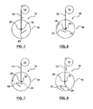
- FIG. 1 schematically illustrates a portion of an apparatus 10 for forming a wave form for a stent from a stent wire 12.
- a supply 14 of the wire 12 is provided to the apparatus 10.
- the supply 14 may include a spool upon which the wire 12 is wound.
- Tension wires 18 and 20 are attached at one end to a plate 16.
- Tension wires 18 and 20 are also fixed at an end opposite plate 16 such that tension wires 18, 20 are in tension and are generally perpendicular/orthogonal to wire 12.
- Tension wires 18, 20 are spaced apart from each other such that wire 12 may be disposed between tension wires 18, 20, as will be described in more detail below.
- supply 14 may be any device or method for providing a supply of wire 12 and feeding or pushing the wire 12 through the space between tension wires 18, 20.
- Wire 12 may have any suitable diameter for the intended stent application.
- wire 12 may have a diameter between about 63 ⁇ m (0.0025 inch) and about 190 ⁇ m (0.0075 inch).
- Wire 12 may be formed of any material suitable for the intended application.
- wire 12 may be formed from stainless steel, nickel-titanium alloys (Nitinol TM ), cobalt-chromium alloys (e.g. L605, MP35N), composite wire ( e.g .
- tension wires 18, 20 may be made of any suitable material and have any suitable diameter to bend wire 12, as described in detail below, and provide adequate durability in the process for bending wire 12.
- tension wires 18, 20 are made from a nickel-titanium alloy (NitinolTM) and have a diameter of in the range of about 76 ⁇ m (.003 inch) to about 254 ⁇ m (.010 inch).
- Plate 16 is shown circular in the drawings. However, plate 16 may be any suitable shape to perform the function of holding tension wires 18, 20 in tension, and rotating such that tension wires 18, 20 bend wire 12, as described in more detail below.
- one end of each of the tension wires 18, 20 is attached to the plate 16 and the opposite end of each of the tension wires 18, 20 is attached to a device to keep the tension wires 18, 26 in tension.
- the tension device may be a weight or a tension motor. An embodiment using a tension motor is described in more detail below.
- Supply 14 pushes wire 12 through the space between tension wires 18, 20, as shown in FIG. 2 .
- Supply 14 may be controlled by a controller such that the length of wire 12 pushed between tension wires 18, 20 is controlled.
- plate 16, with tension wires 18, 20 attached thereto rotates in a direction such that tension wires 18, 20 also rotate, as shown in FIG. 3 .
- plate 16 rotates counter-clockwise, as indicated by the arrow in FIG. 3 .
- tension wires 18, 20 bend the portion of wire 12 that is disposed in the space between tension wires 18, 20.
- the amount of rotation of plate 16 controls the amount of bend on wire 12.
- plate 16 may rotate between 90 and 180 degrees to bend wire 12 to create a first crown 22 in wire 12.
- plate 16 is rotated in a clockwise direction back to the neutral position, as shown in FIG. 4 .
- tension wires 18, 20 are sufficient space between tension wires 18, 20 such that wire 12 is not bent by the return of plate 16 back to the neutral position.
- Supply 14 then pushes wire 12 the desired length of the amplitude of the waveform, as shown in FIG. 5 .
- Plate 16 then rotates in a clockwise direction, as shown in FIG. 6 , such that tension wires 18, 20 rotate with wire 12 disposed therebetween.
- tension wires 18, 20 bend the portion of wire 12 disposed in the space between tension wires 18, 20.
- plate 16 Due to rotation of plate 16 in the opposite direction of the previous rotation, a second crown 24 is formed in wire 12 in the opposite direction of the first crown 22, thereby completing a wave of the waveform.
- plate 16 is returned to the neutral position by rotating plate 16 back in the counter-clockwise direction, as shown in FIG. 7 .
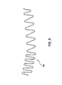
- FIG. 9 illustrates an embodiment of a wave form 40 that may be produced by apparatus 10 utilizing the method described above.
- a controller coupled to supply 14 and the motor (not shown) used to rotate plate 16 may control each feed of wire 12 and each rotation of plate 16.
- each wave that is formed may be different, i.e ., may have a different amplitude, wavelength, shape, etc., as compared to adjacent waves.
- each wave of the wave form may have a unique amplitude and wavelength.
- FIGS. 10-21 illustrate schematically a portion of an apparatus 100 for forming a wave form for a stent from a stent wire 112 in accordance with another embodiment herein.
- wire 112 is provided to the apparatus 100 by a supply 114, which may include a spool upon which the wire 112 is wound.
- apparatus 100 includes a first die or wire holder 116 and a second die or wire holder 117.
- Wire holders 116, 117 are disposed adjacent to each other along parting lines 128, 126 respectively. In the embodiment shown, parting lines 128, 126 are curved.
- stent wire 112 is prevented from sliding between wire holders 116, 117 during the forming process, described in more detail below.
- Stent wire 112 is supported by a portion of wire holder 116 or a portion of wire holder 117 throughout the wave forming process.
- Each wire holder 116, 117 includes a recess or groove 130, 132 sized to retain a corresponding tension wire 118, 120 therein.
- Tension wires 118, 120 may be the same as tension wires 18, 20 described above.
- Tension wires 118, 120 extend generally perpendicular/orthogonal to stent wire 112 such that stent wire 112 is disposed between tension wires 118, 120.
- tension wires 118, 120 may extend generally vertically and stent wire 112 may extend generally horizontally.
- tension wires 118, 120 extend through wire holders 116, 117, as will be described in more detail below.
- Tension wires 118, 120 are held in tension by means known to those skilled in the art.
- corresponding ends of tension wires 118, 120 may be secured and a weight or motor coupled thereto to provide a tensile force.
- An embodiment of a tension motor driver is described in more detail below and can be used with any of the embodiments described herein.
- other apparatus and methods for providing a tensile force to tension wires 118, 120 may be utilized.
- wire holders 116, 117 may translate laterally and rotate. Although the arrows in FIG. 10 show wire holders 116, 117 translating generally perpendicular to the direction of the stent wire, wire holders 116, 117 may translate at any position along its rotation. Thus, for example, and not by way of limitation, if wire holders 116, 117 are rotated approximately 90 degrees, translation of the wire holders 116, 117 would be generally parallel to the stent wire 112.
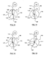
- wire holders 116, 117 are moved apart from each other and supply 114 feeds a length of stent wire 112 between tension wires 118, 120, as shown in FIG. 11 .
- wire holders 116, 117 are moved towards each other such that tension wires 118, 120 are closely adjacent to/abutting stent wire 112.
- wire holders 116, 117 are shifted to the left such that the right tension wire 118 is aligned with the center of rotation of the wire holder 116, 117, as shown in FIG. 12 .
- right tension wire 118 does not translate during rotation, behaving like a rotary pipe bending die around which stent wire 112 is bent, as shown in FIG. 22 .
- the wire holders 116, 117 are rotated in a counter-clockvvise direction, as shown in FIG. 13 .
- This rotation causes the left tension wire 120 to rotate around the right tension wire 118 if the right tension wire is located at the center of rotation.
- Such a rotation causes the stent wire 112 disposed between tension wires 118, 120 to bend, as shown in FIG. 13 , thereby forming a first crown 122 in the stent wire 112.
- the wire holders 116, 117 are then translated to separate from each other such that the gap between the tension wires 118, 120 is increased, as shown in FIG. 14 . This permits the wire holders 116, 117 to return to the neutral position through a clockwise rotation of wire holders 116, 117, as shown in FIG. 15 , without bending stent wire 112. With wire holders 116, 117 still separated, another length of stent wire 112 is fed from supply 114, as shown in FIG. 16 .
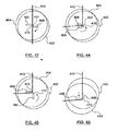
- wire holders 116, 117 are translated towards each other and shifted to the right such that tension wires 118, 120 are closely adjacent to/abutting stent wire 112 and left tension wire 120 is disposed at the center of rotation of the wire holders 116, 117, as illustrated in FIG. 17 .
- Wire holders 116, 117 are then rotated in a clockwise direction, as shown in FIG. 18 .
- This rotation causes the right tension wire 118 to rotate around the left tension wire 120 if the left tension wire 120 is located at the center of rotation.
- Such a rotation causes the stent wire 112 disposed between tension wires 118, 120 to bend as if in a rotary type pipe bender, as shown in FIG. 18 , thereby forming a second crown 124 in the stent wire 112 and completing a wave of the waveform.
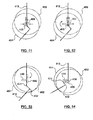
- the wire holders 116, 117 are then translated to separate from each other such that the gap between the tension wires 118, 120 is increased, as shown in FIG. 19 .
- another length of stent wire 112 is fed from supply 114, as shown in FIG. 21 .
- the above-described steps may then be repeated as many times as desired to complete the desired waveform.
- the size and shape of each individual wave may be controlled by controlling the length of stent wire 112 fed from supply 114 and the amount of rotation of wire holders 116, 117.
- a waveform with varying wave lengths, amplitudes, and degree of bend in the crowns may be created from a single stent wire.
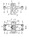
- FIGS. 23-39 show an embodiment of an apparatus 200 for forming a waveform in a stent wire.
- Apparatus 200 utilizes the principles discussed above with respect to apparatus 100 in that a pair of wire holders are used that can translate and rotate and are utilized to hold tension wires that form crowns in the stent wire.
- the description of apparatus 200 includes many details of specific embodiments for operating the wire holders, tension wires, and feeding the stent wire. Those skilled in the art would recognize that the various features described with respect to apparatus 200 can be used, individually or in combination, as appropriate in the other embodiments described herein.
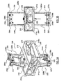
- FIG. 23 is a perspective view of apparatus 200.
- Apparatus 200 includes a base plate 209, and stand base 202, and legs 206 attached at each end to the base plate 209 and stand base 202. Further, brake wheels 204 are attached to the stand base.
- the base plate 209, stand base 202, and legs 206 provide support for the base plate assembly 208 ( FIG. 24 ), which includes many of the elements for forming a waveform in a stent wire.
- Apparatus 200 further includes an electronics panel 224, which houses a power supply, servo drives, and other electronics known to those of ordinary skill in the art that are needed or desired for the parts described herein.
- left and right upper shelf side supports 210a, 210 b are attached to base plate 209.
- Left and right upper shelf side supports 210a, 210b support a front upper shelf 212 and a rear upper shelf 214.
- Front upper shelf 212 includes a guide tray 213 attached thereto.
- Left and right inner upper shelf supports 211 a, 211 b extend from the left and right upper shelf side supports 210 a , 210 b towards the interior of apparatus 200 to further support the upper shelf 212, 214, as illustrated in FIGS. 25 and 26 .
- a feed axis center support 215 Disposed in the rear portion of the base assembly 208 between the rear upper shelf 214 and the base plate 209 are a feed axis center support 215, left and right feed axis side supports 217 a , 217 b , and a feed axis support shelf 219, as illustrated in FIG. 26 . These support a feeder assembly 240, described in more detail below.
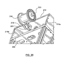
- a spool 216 for holding a supply of the stent wire is attached to the rear upper shelf 214, as shown generally in FIG. 23 .
- a bracket 219 is attached to the lower surface of the rear upper shelf 214.
- a spool arm 218 extends from the bracket 219 to the rear of rear upper shelf 214.
- a spindle 223 extends from spool arm 218.
- Spool 216 includes an opening 216 a and spindle 223 extends through opening 216 a to support spool 216.
- An upper tension drive assembly 220 is attached to rear upper shelf 214 and extends upwardly, as shown in FIGS. 23-28 .
- Upper tension drive assembly 220 includes left and right upper tension drive risers 226 a , 226 b attached to the rear upper shelf 214.
- An upper tension motor plate 230 is attached to the left and right tension upper drive risers 226 a , 226 b and spans the gap therebetween.
- the upper tension motor plate 230 serves as a mounting plate for left and right upper tension motors 234 a , 234 b .
- Left and right upper tension motors 234 a , 234 b are operatively connected to left and right upper pulleys 236 a , 236 b , respectively.
- the left and right upper tension motors 234 a , 234 b are disposed on a rear side of upper tension motor plate 230
- the left and right upper tension pulleys 236 a , 236 b are disposed on a front side of upper tension motor plate 230
- left and right motor shafts extend through respective openings in the upper tension motor plate 230 to operatively connect the left and right upper tension motors 234 a , 234 b to the left and right upper tension pulleys 236 a , 236 b
- Upper tension drive assembly further includes left and right upper guide pulleys 238 a , 238 b , as shown.
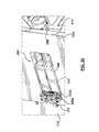
- Lower tension drive assembly 222 is attached to base plate 209 and extends downwardly, as shown in FIGS. 23-28 .
- Lower tension drive assembly 222 includes left and right lower tension drive risers 228 a , 228 b attached to the base pate 209.
- a lower tension motor plate 232 is attached to the left and right lower tension drive risers 228 a , 228 b and spans the gap therebetween.
- the lower tension motor plate 232 serves as a mounting plate for left and right lower tension motors 234 c , 234 d .
- Left and right lower tension motors 234 c , 234 d are operatively connected to left and right lower pulleys 237 a , 237 b , respectively.
- the left and right lower tension motors 234 c , 234 d are disposed on a rear side of lower tension motor plate 232
- the left and right lower tension pulleys 237 a , 237 b are disposed on a front side of lower tension motor plate 232
- left and right motor shafts extend through respective openings in the upper tension motor plate 230 to operatively connect the left and right lower tension motors 234 c , 234 d to the left and right lower tension pulleys 237 a , 237 b
- Lower tension drive assembly further includes left and right lower guide pulleys 239 a , 239 b , as shown.
- Left and right upper tension motors 234 a , 234 b and left and right lower tension motors 234 c , 234 d may be, for example and not by way of limitation, Danaher AKM gear motors, such as the Danaher AKM-21x, or other similar motors.
- left and right tension wires 318, 320 are maintained in tension by the upper and lower tension drive assemblies 220, 222.
- Left and right tension wires 318, 320 may be similar to tension wires 18, 20 and 118, 120 described with respect to the embodiments above.
- left tension wire 318 is wound around upper left pulley 236 a , extends along an inner or right side of left upper guide pulley 238 a , and down through the left wire holder (not shown in FIG. 28 ).
- the left tension wire 318 continues downward along the inner or right side of left lower guide pulley 239 a and is wound around lower left pulley 237 a .
- right tension wire 320 is wound around upper right pulley 236 b , extends along an inner or left side of right upper guide pulley 238 b , and down through the right wire holder (not shown in FIG. 28 ).
- the right tension wire 320 continues downward along the inner or left side of right lower guide pulley 239 b and is wound around lower left pulley 237 b .
- tension motors 234 a , 234 b , 234 c , 234 b provide a force to maintain tension wires 318, 320 in tension.
- left upper tension motor 234 a provides a counter-clockwise force
- left lower tension motor 234 c provides a clockwise force to maintain left tension wire 318 in tension, as indicated by the arrows in FIG. 28 .
- Right upper tension motor 234 b provides a clockwise force
- right lower tension motor 234 d provides a counter-clockwise for to maintain right tension wire 320 in tension, as also indicated by the arrows in FIG. 28 .
- each of the tension motors may also step in the opposite direction in order to move the respective tension wire.
- upper right tension motor 236b may step in the counter-clockwise direction and lower right tension motor 236 d may step the corresponding amount in the clockwise direction such that right tension wire 318 shifts downward.
- These steps may be as small as to move the corresponding tension wire 25 ⁇ m (.001 inch).
- This movement reduces wear on the tension wires 318, 320, which provide longer life for the tension wires and reduces wear marks or variations on the stent wire when the stent wire is bent by the tension wires.
- each of the tension wires 318, 320 may be shifted up or down such that a "afresh" portion of the tension wires is used for the next crown.
- the tension wires may be shifted by the length of the portions of the tension wires that contact the stent wire during the formation of each crown, e.g . 50 ⁇ m (.002 inch), after each crown is formed. In forming 1000 crowns, only 5 cm (2 inches) of the tension wires will be utilized, and each crown is formed using an unworn portion of the tension wires.
- the tension wires 318, 320 may be spooled around the respective pulleys 236 a , 237 a , 236 b , 237 b such that tens of thousands of crowns may be formed without using the same portion of the tension wires 318, 320 more than once.
- the tension wires 318, 320 have moved to their limit in one direction, the tension wires 318, 320 can be shifted incrementally in the opposite direction to form tens of thousands more crowns wherein the portion of the tension wires 318, 320 forming each crown has only been used once. This process can be repeated as many times as desirable and reduces damage to the stent wires caused by wear on forming members that occurs in other methods and apparatus for forming waves in a stent wire.
- FIG. 30 shows a perspective view of rotation assembly 270.
- Rotation assembly 270 includes wire holders 300 a , 300 b coupled to stepper motors 272 a , 272 b to translate wire holders 300 and coupled to a rotary motor 290 (see FIG. 35 , inner top 298 of rotary motor 290 is shown in FIG. 30 ) to rotate wire holders 300.
- FIG. 30 shows wire holders 300 a , 300 b operatively connected to stepper motors 272 a , 272 b and rotary motor 290 (not shown in FIG. 30 ; inner top 298 of rotary motor 290 is shown in FIG. 30 ).
- Wire holders 300 a , 300 b are an embodiment of wire holders 116, 117 described above with respect to FIGS. 10-21 .
- FIG. 31 shows a single wire holder 300.
- Wire holders 300 a , 300 b are mirror images such that description of wire holder 300 referring to FIG. 31 applies to both wire holders 300 a , 300 b . As shown in FIG.
- each wire holder 300 includes a generally semi-cylindrical portion 302 with a curved parting surface 304 and a groove 306.
- the curved parting surface 304 of each wire holder defines where wire holders 300a, 300 b separate from each other and come together towards each other.
- the groove 306 in each wire holder 300 is sized and configured to hold one of tension wires 318, 320 therein.
- Wire holders 300a, 300 b together are generally cylindrical in shape and each has a base 308 to connect the respective wire holder 300 to the respective stepper motor 272.
- Stepper motors 272 a , 272 b are shown in FIGS. 30 and portions thereof are shown in FIGS. 32-34 . As with wire holders 300, a stepper motor 272 and associated connectors to a respective wire holder will be described with respect to FIGS. 32-34 . As is apparent, steppers motors 272 a , 272 b are the same except that they are mounted to carriage plate 298 in opposite directions.
- each wire holder 300 is mounted to wire holder adjuster 307.
- Wire holder adjuster 307 is mounted to wire holder mount 308 by wire holder clamp 309.
- Wire holder mount 308 is attached to a carriage block 310, which moves with the movement of stepper motor 272, thereby moving the wire holder 300.
- Carriage plate 310 is part of stepper motor 272, described in detail below, and is coupled to a screw 281 (see FIG. 34 ) of stepper motor 272 by a screw nut 317 which is coupled to carriage plate 310 by a nut block 305.
- Carriage block 310 moves along cross roller rails 311.
- Home flag 315 and limit flags 314, 316 are coupled to carriage block 310 and coordinate with home sensor 286 and limit sensors 285, 287 (see FIG. 34 ) to provide feedback regarding the location of carriage plate 310, and hence the location of wire holder 300.
- Dowel pins 313 are also coupled to carriage block 310 (only one of two dowel pins is shown in the figures). Dowel pins 313 prevent carriage block 310 from moving beyond a certain point in each direction when a respective dowel pin 313 hits a limit stop 284 (see FIG. 34 ).
- Stepper motor 272 with carriage block 310 removed, is shown in FIG. 34 . It is apparent that stepper motor 272 described herein is exemplary and that other stepper motors or similar devices may be used to move wire holders 300 a , 300 b . Stepper motor 272 described herein may be, for example and not by way of limitation, an AM1-0401-3S motorized staged AM series motor available from Micro Motion Technology, LTD. A modular encoder 274 may be coupled to stepper motor 272. For example, and not by way of limitation, an R35i series modular encoder available from RENCO encoders, Inc. may be utilized. As shown in FIG. 34 , stepper motor 272 further includes a stepping motor 276 mounted to a motor bracket 278, which is mounted to a base plate 280.
- a stepping motor 276 mounted to a motor bracket 278, which is mounted to a base plate 280.
- Base plate 280 includes a support block 282 and end block 283 mounted thereon. Support block 280 and end block 283 support a screw 281 therebetween. Rotation of screw 281 causes carriage block 310 to translate by the connection through screw nut 317.
- Cross roller rails 311 are also mounted to base plate 280, although only one is shown in FIG. 34 .
- a limit stop 284 is also mounted to base plate 280. With carriage block 310 coupled to screw 281; limit stop 284 is disposed between dowels 313 coupled to carriage block 310. Thus, dowels 313 and limit stop 284 limit the movement of carriage block 310 in each direction because limit stop 284 will hit one of the dowels 313, depending on which direction carriage block 310 is moving.
- Home sensor 286 and limit sensors 285, 287 are also coupled to base plate 280 via a sensor block 279. Sensors 285, 286, 287 are disposed such that flags 314, 318, 316 mounted on carriage block 310 trigger sensors 285, 286, 287 to provide feedback to a control unit regarding the location of carriage block 310.
- the stepper motors 272 a , 272 b and thus the wire holders 300a, 300 b coupled thereto, are mounted on a carriage plate 288.
- Carriage plate 288 is attached to an inner top 298 of a rotary motor 290.
- rotary motor includes a body 294, a base 292, an outer ring 296, and inner top 298.
- Rotary motor 290 rotates inner top 292 in a clockwise or counter-clockwise direction, thereby rotating carriage plate 288 and the items mounted thereon, in a clockwise or counter-clockwise direction. Consequently, rotary motor 290 rotates wire holders 300 a , 300 b in a clockwise or counter-clockwise direction.
- Outer ring 296 and inner top 292 may each include a home marker 297 indicating the home or neutral position of inner top 298.
- Rotary motor 290 also includes cables/bushings 299 as known to those skilled in the art.
- Rotary motor 290 may be any rotary motor that can rotate carriage plate 288 as desired.
- rotary motor 290 may be an ACD series coreless torque motor available from Motion Control Products LTD.
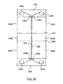
- FIGS. 36-39 illustrate an embodiment of a feed assembly 240 to feed a stent wire into the forming area between tension wires 318, 320.
- feed assembly 240 to feed a stent wire into the forming area between tension wires 318, 320.
- FIGS. 36-39 illustrate an embodiment of a feed assembly 240 to feed a stent wire into the forming area between tension wires 318, 320.
- feed assemblies may be utilized.
- feed assembly 240 includes a feed axis arm 242 including a groove 244.
- Feed assembly 240 further includes a first brake assembly 250 a and a second brake assembly 250 b , described in detail below.
- the stent wire is fed through openings in the brake assemblies 250 a , 250 b and over a lower wear plate 246, shown in FIG. 37A .
- FIG. 37B illustrates the same area of FIG. 37A except that an upper guide plate 248 is shown covering the general area of the lower wear plate 246. In operation, the stent wire is fed between lower wear plate 246 and upper guide plate 248 in order to guide the stent wire to the forming area at wire holders 300 a , 300 b .
- Feed axis arm 242 is operatively coupled to a feed motor 260, as illustrated in FIG. 36 .
- Feed motor 260 in this embodiment is the same as stepping motors 272 except that the carriage block of feed motor 260 is attached to feed axis arm 242 rather than to the wire holder mount 308.
- Feed motor 260 operates to translate feed axis arm back and forth in the longitudinal direction of groove 244.
- feed motor 260 is shown and described as being the same as stepping motors 272, those of ordinary skill in the art will recognize that feed motor can be any device that can move feed axis arm 242 in the longitudinal direction.
- Feed motor 260 may be, for example and not by way of limitation, an AM1-0401-3S motorized staged AM series motor available from Micro Motion Technology, LTD.
- Brake assemblies 250 a , 250 b operate to hold or release the stent wire so as to feed the stent wire into the forming area.
- Front brake assembly 250 a is mounted to the rear upper shelf 214 and is substantially fixed. In an embodiment, front brake assembly may shift slightly laterally such that the stent wire is aligned when the wire holders 300 shift to align the center of rotation with one of the tension wires 318, 320, as described above with respect to FIGS. 10-21 .
- Rear brake assembly 250 b is operatively coupled to feed axis arm 242 such that rear brake assembly 256 b moves with feed axis arm 242.
- Brake assemblies 250 a , 250 b in the present embodiment are identical and thus one brake assembly 250 is illustrated and described in FIGS. 38-39 . Those of ordinary skill in the art will recognize that the description applies to both brake assemblies. Further, those of ordinary skill in the art will recognize that the brake assemblies 250 a , 250 b do not need to be the same and do not need to be as described herein. Other assemblies for feeding the stent wire into the forming area may also be used.
- Brake assembly 250 includes brake flexure base 252 for mounting the brake assembly to the upper rear shelf 214 or the feed axis arm 242. Brake assembly 250 further includes a brake bridge 254 coupled at each end thereof to the brake flexure base 252.
- a brake flexure top side 256 is disposed on a top portion of brake flexure base 252.
- a piezo actuator 258 is mounted between brake bridge 254 and brake flexure top side 256.
- each of brake flexure base 252 and brake flexure top side 256 includes a respective groove 262, 264 in the mating surfaces thereof to form a hole through which the stent wire is fed.
- Piezo actuator 258 may be any device that can apply pressure to brake flexure top side 256 such that a gripping pressure is applied to the sent wire disposed between brake flexure top side 256 and brake fiexure base 252.
- piezo actuator 258 is actuated to compress in the direction of arrows 266 such that the portions of piezo actuator 258 attached to brake bridge 254 and brake flexure top side 256 expand in the directions shown by arrows 268. This expansion provides a force against brake flexure top side 256 that compressed the hole formed by grooves 252, 254, thereby gripping a sent wire disposed in the hole.
- Piezo actuator 258 may be, for example and not by way of limitation, a piezo actuator in the Amplified Piezo Actuator Series available from Cedrat Technologies, such as model APA-60S.
- second brake assembly 250 b is actuated such that a gripping pressure is applied to the stent wire, while first brake assembly 250 a remains un-actuated such that the stent wire may pass therethrough.
- feed motor 260 is actuated to move feed axis arm 242 towards the feed area, thereby also moving second brake assembly 250 b , and the stent wire captured therein, towards the feed area. This movement can also be described as moving the feed axis arm 242 and the second brake assembly 250 b towards the first brake assembly 250 a .
- the first brake assembly 250 a is then actuated to grip the stent wire while the second brake assembly 250 b is un-actuated to release the stent wire and the feed motor 260 moves feed axis arm 242 away from the feed area/first brake assembly 250 a .
- a length of the stent wire is moved into the feed area while the second movement returns the feed axis arm 242 and second brake assembly 250 a to a neutral position while the first brake assembly 250 a holds the stent wire in place such that the stent wire is not retracted from the feed area.
- This process is repeated for each length of the stent wire fed into the forming area to bend the stent wire to form a wave of the waveform.
- a controller 330 communicates with the first and second stepping motors 272 a , 272 b , the rotary motor 290, the feed motor 260, the piezo actuators 258 of the first and second brake assemblies 250 a , 250 b , and the left upper, right upper, left lower, and right upper tension motors 234 a , 234 b , 234 c, 234 d .
- the piezo actuators 258 and feed motor 260 are controlled to feed the stent wire into the wire forming area between the tension wires 318, 320
- the first and second stepping motors 272 a , 272 b are controlled to translate wire holders 300 a , 300 b such as to bring the wire holders together, separate them, or shift them such that the axis of rotation is aligned with one of the tension wires 318, 320
- the rotary motor 290 is controlled to rotate wire holders 300a, 300b and thus rotate wires 318, 320
- the tension motors 234 are controlled to keep tension wires 318, 320 in tension and to shift tension wires 318, 320 longitudinally after each bend of the stent wire in order to minimize wear.
- the controller 330 may signal the motors and actuators described above so the apparatus 200 forms the desired wave form.
- FIGS. 40-55 illustrate schematically an apparatus 400 for forming a waveform in a stent wire 412 and a method for forming a waveform in a stent wire in accordance with another embodiment hereof.
- apparatus 400 uses forming members, as will be described in more detail below.
- Apparatus 400 includes an upper or first drum or cylinder 402 and a lower or second drum or cylinder 404.
- First drum 402 includes a first surface 414 and second drum 404 includes a second surface 416. First surface 414 and second surface 416 face each other.
- First drum 402 further includes a first bending or forming member 406 disposed on first surface 414.
- Second drum 404 includes a second bending or forming member 408 disposed on second surface 416.
- First drum 402 and second drum 404 may move independently of each other and each may rotate in either direction and may translate in four directions, in an x-y plane, as indicated by the arrows in FIG. 40 .
- First and second drums 402, 404 may be rotated, about a local z-axis, and translated by mechanisms known to those skilled in the art. For example, and not by way of limitation, the mechanisms described above for rotation and translation may be utilized. Further, although drums 402, 404 are shown as generally cylindrical drums, those skilled in the art would recognize that they can be different shapes provided that they can perform the functions described below.
- Forming members 400, 408 may be elongated members with rounded ends.
- forming members 406, 408 may be generally rectangular in shape with rounded ends 418, 419 and 420, 421 instead of straight ends, as illustrated in FIG. 41 .
- Each forming member 406, 408 is mounted to the respective surface 414, 416 of the respective drum 402, 404 such that a center of rotation 410, 411 of rounded end 418, 419 of the forming member 406, 408 is aligned with the center of rotation of the respective drum 402, 404.
- the forming members may be different shapes.
- FIG. 42 illustrates schematically an embodiment of a forming member 422.
- Forming member 422 is generally triangular in shape with rounded edges 424, 426, 428 at the apices of the triangle.
- FIG. 42 illustrates a plan view of forming member 422.
- Forming member 422 also includes a depth or thickness, as is apparent from FIG. 40 . If forming members such as forming member 422 are used, forming members 422 would be mounted to drums 402, 404 such that a center of rotation 430 of a rounded apex 424 of forming member 424 is aligned with a center of rotation of the drum 402, 404 to which forming member 422 is mounted.
- Forming members 406, 408, or 422 may be made of any material suitable to withstand the wear of bending the stent wire, as described below, and sufficiently smooth so as not to create unwanted surface marks or deformations in the stent wire.
- the forming members may be made of hardened tool steel (high speed steel), tungsten alloys or tungsten-carbide, cobalt or cobalt-steel alloys.
- the surface of the forming member 406,408,422 may also be coated to reduce wear.
- the forming members may be coated with black oxide, titanium nitride (TiN), titanium aluminum nitiride (TiAlN), titanium carbon nitride (TiCN), aluminium chromium silicon nitride (AlCrSiN), titanium silicon nitride (TiSiN), or diamond.
- TiN titanium nitride
- TiAlN titanium aluminum nitiride
- TiCN titanium carbon nitride
- AlCrSiN aluminium chromium silicon nitride
- TiSiN titanium silicon nitride
- diamond diamond
- FIGS. 43-54 illustrate schematically an embodiment of operation of apparatus 400 in an embodiment of a method of forming a waveform in a stent wire 412.
- FIG. 43 shows a length of stent wire 412 already fed between forming members 406, 408 and between first surface 414 of first drum 402 and second surface 416 of second drum 404.
- Stent wire 412 may be fed by devices and methods described above for feeding a stent wire, other devices and methods known to those skilled in the art, or using the forming members 406, 408 and movement of the drums 402, 404, as will be described below.
- Stent wire 412 is disposed between forming members 406, 408 with forming members disposed generally perpendicular to stent wire 412. Further, forming members 406, 408 are offset from each other along the direction of stent wire 412, as shown schematically in FIG. 43 .
- Forming members 406, 408 are disposed with respective ends 418, 419 with centers of rotation 410, 411 aligned with the centers of rotation of drums 402, 404 adjacent sent wire 412, as shown in FIG. 43 .
- first drum 402 is rotated clockwise approximately 180 degrees, resulting in the first forming member 406 rotating around end 418 such that first forming member is generally parallel to second forming member 408, as shown in FIG. 44 .
- stent wire 412 is bent by first and second forming members 406, 408, as shown schematically in FIG. 44 , to create a first crown 432 in stent wire 412.
- first drum 402 is rotated counter-clockwise approximately 90 degrees as indicated by the arrow in FIG. 44 , resulting in first forming member 406 being generally perpendicular to second forming member 408, as shown in FIG. 45 .
- First drum 402 continues its clockwise rotation another approximately 180 degrees, as indicated by the arrow in FIG. 45 , resulting in the first forming member 406 rotating around end 418, as shown schematically in FIG. 46 .
- second drum 404 is translated in a direction generally parallel to the feed direction of stent wire 412, as indicated by the arrow in FIG. 46 , resulting in stent wire 412 being pushed by first forming member 406, as shown in FIG. 47 .
- This movement results in a length of stent wire 412 disposed between first crown 432 and first forming member 406, as shown in FIG. 47 .
- This movement also results in second drum 404 being offset from first drum 402 such that second forming member 408 is offset from first forming member 406, as also shown in FIG. 47 .
- second drum 404 and corresponding second forming member 408 are translated in a direction opposite the feed direction of stent wire 412 back to the position shown in FIG. 46 , as shown in FIG. 48 .
- This movement results in the first and second forming members 406, 408 being located in positions to form a second crown 434.
- second drum 404 is rotated counter-clockwise such that corresponding second forming member 408 rotates counter-clockwise, as indicated by the arrow in FIG. 48 .
- the rotation of second forming member 408 causes the portion of stent wire 412 disposed between second forming member 408 and first forming member 406 to bend to form a first portion of second crown 434, as shown in FIG. 49 .
- second drum 404 and corresponding second forming member 408 are rotated clockwise, as indicated by the arrows in FIGS. 49 and 50 .
- This rotation results in first and second forming members 406, 408 being parallel to each other and parallel to the feeding direction of stent wire 412, as shown in FIG. 51 .
- first and second drums 402, 404 are translated towards each other such that first and second forming members 406, 404 move towards each other and towards stent wire 412, which is disposed between the first and second forming members 406, 408, as indicated by the arrows in FIG. 51 .
- the first and second forming members 406, 408 apply sufficient pressure on stent wire 412 such that stent wire 412 moves with first and second forming members 406, 408.
- first and second drums 404, 404 are then translated together in the feed direction of stent wire 412, as also indicated by the arrows if FIG. 51 . This movement results in a length of stent wire 412 being fed from the stent wire supply (not shown).
- first and second drums 402, 404 are translated away from each other such that first and second forming members 406, 408 move apart from each other to relieve the pressure applied to stent wire 412, as indicated by the arrows in FIG. 52 .
- First and second drums 402, 404 are also translated in a direction opposite the feed direction of stent wire 412, as also indicated by the arrows in FIG. 52 .
- This movement of first and second drums results in a length of stent wire 412 being disposed between the first portion of second crown 434 and first and second forming members 406, 408, as shown in FIG. 53 .
- Second drum 404 is also rotated in a clockwise direction, as indicated by the rotational arrow in FIG. 53 , resulting in second forming member 408 being generally perpendicular to first forming member 406, as shown in FIG. 53 .
- first drum 402 is translated in the feed direction of stent wire 412, as indicated by the arrow in FIG. 53 , thereby translating first forming member 406 in the feed direction.
- First drum 402 is then rotated clockwise as indicated by the rotational arrow in FIG. 53 , resulting in first forming member 406 rotating to bend stent wire 412 disposed between first forming member 406 and second forming member 408 to form the second portion of second crown 434 to complete a wave of the waveform and to form a third crown 436, which is the first crown of the next wave of the waveform, as illustrated schematically in FIG. 54 .
- each individual wave may be controlled by controlling the length of stent wire 412 fed from between first and second forming members 406, 408 and the amount of rotation of first and second drums 402, 404.
- a waveform with varying wave lengths, amplitudes, and degree of bend in the crowns may be created from a single stent wire.
- the stent wire 412 may be fed by movement of first and second drums 402, 404 and corresponding first and second forming members 406, 408.
- the supply for stent wire 412 may simply be a spool of stent wire 412 or other similar supply.
- an active feed system may be provided for stent wire 412, such as the feed assembly 240 described in other embodiments herein or known to those skilled in the art, and the steps described above for feeding stent wire 412 using first and second forming members 406, 408 may be eliminated.
- FIG. 55 schematically illustrates communication between a controller 440 and other parts of the apparatus 400 that are illustrated in FIGS. 40-54 .
- the controller 440 is configured to communicate with the first drum 402 and second drum 404.
- first and second drums 402, 404 are configured to rotate and translate.
- the devices used to rotate and translate first and second drums 402, 404 such as linear slides/actuators, stepping motors, and rotary motors (not shown), communicate with controller 440.
- the controller 440 may signal the first drum 402 and second drum 404 so the apparatus 400 forms the desired wave form.
Landscapes
- Engineering & Computer Science (AREA)
- Health & Medical Sciences (AREA)
- Mechanical Engineering (AREA)
- General Health & Medical Sciences (AREA)
- Heart & Thoracic Surgery (AREA)
- Vascular Medicine (AREA)
- Biomedical Technology (AREA)
- Cardiology (AREA)
- Oral & Maxillofacial Surgery (AREA)
- Transplantation (AREA)
- Life Sciences & Earth Sciences (AREA)
- Animal Behavior & Ethology (AREA)
- Public Health (AREA)
- Veterinary Medicine (AREA)
- Media Introduction/Drainage Providing Device (AREA)
Claims (15)
- Vorrichtung (10,100, 200) zum Bilden einer Wellenform (40) für einen Stent aus einem Stent-Draht (12,112), wobei die Vorrichtung gekennzeichnet ist durch
einen ersten Spanndraht (18, 118, 318);
einen zweiten Spanndraht (20, 120, 320), der im Wesentlichen parallel zum ersten Spanndraht angeordnet ist und einen Spalt zwischen dem ersten Spanndraht (18,118, 318) und dem zweiten Spanndraht (20, 120, 320) aufweist, der ausreichend groß ist, damit der Stent-Draht (12, 112) im Spalt angeordnet werden kann, wobei der erste und zweite Spanndraht (18, 118, 318, 20, 120, 320) gespannt sind; und
einen Drahthalter (16, 116,117, 300), der an den ersten Spanndraht und den zweiten Spanndraht gekoppelt ist, wobei der Drahthalter (16, 116, 117, 300) dazu konfiguriert ist, den ersten und zweiten Spanndraht im Uhrzeigersinn und gegen den Uhrzeigersinn um eine Drehachse zu drehen, die im Wesentlichen parallel zum ersten und zweiten Spanndraht (18, 118, 318, 20, 120, 320) ist, wobei der Stent-Draht (12, 112) derart in dem Spalt angeordnet ist, dass der erste und zweite Spanndraht eine Biegung in einer ersten Richtung oder einer zweiten Richtung entgegengesetzt zur ersten Richtung im Stent-Draht (12, 112) bilden. - Vorrichtung (10, 100, 200) nach Anspruch 1, wobei der Drahthalter eine Platte (16) ist und ein erstes Ende von jedem von dem ersten und zweiten Spanndraht (18, 118, 318, 20, 120, 320) an der Platte (16) angebracht ist und ein zweites Ende von jedem von dem ersten und zweiten Spanndraht gespannt gehalten wird.
- Vorrichtung (10, 100, 200) nach Anspruch 1, wobei der Drahthalter einen ersten Drahthalter (116, 300a), der an den ersten Spanndraht (18, 118, 318) gekoppelt ist, und einen zweiten Drahthalter (117, 300b) aufweist, der an den zweiten Spanndraht (20, 120, 320) gekoppelt ist, wobei der erste Drahthalter und der zweite Drahthalter in Richtungen verlagerbar sind, die im Wesentlichen orthogonal zur Drehachse sind, derart, dass der erste und der zweite Drahthalter (116,117) und der erste und der zweite Spanndraht (18, 118, 318, 20, 120, 320) zueinander hin und voneinander fort bewegt werden können und derart verschoben werden können, dass der erste Spanndraht (18, 118, 318) oder der zweiten Spanndraht (20, 120, 320) im Wesentlichen an der Drehachse ausgerichtet ist.
- Vorrichtung (10, 100, 200) nach Anspruch 3, wobei der erste Drahthalter (116, 300a) und der zweite Drahthalter (117, 300b) gemeinsam einen allgemein zylindrischen Körper mit einer Trennlinie (128, 126, 304) bilden, die den ersten Drahthalter und den zweiten Drahthalter trennt.
- Vorrichtung (10, 100, 200) nach Anspruch 4, wobei die Trennlinie (128, 126, 304) gekrümmt ist.
- Vorrichtung (10, 100, 200) nach Anspruch 3, wobei der erste Drahthalter (116, 300a) eine erste Nut (130, 306) aufweist, die im Wesentlichen parallel zum ersten Spanndraht (118, 318) ist, wobei die erste Nut dazu konfiguriert ist, den ersten Spanndraht aufzunehmen; wobei wahlweise der zweite Drahthalter (117, 300b) eine zweite Nut (132, 306) aufweist, die im Wesentlichen parallel zum zweiten Spanndraht (120, 320) angeordnet ist, wobei die zweite Nut dazu konfiguriert ist, den zweiten Spanndraht aufzunehmen.
- Vorrichtung (200) nach Anspruch 1, wobei gegenüberliegende Enden des ersten Spanndrahts (318) in Wirkbeziehung an einen jeweiligen ersten Spannmotor (234a, 234c) gekoppelt sind, die dazu konfiguriert sind, eine Spannkraft auf den ersten Spanndraht (318) auszuüben, und gegenüberliegende Enden des zweiten Spanndrahts (320) in Wirkbeziehung an einen jeweiligen zweiten Spannmotor (234b, 234d), gekoppelt sind, die dazu konfiguriert sind, eine Spannkraft auf den zweiten Spanndraht (320) auszuüben; wobei wahlweise wenigstens ein Ende von jedem von dem ersten und zweiten Spanndraht (318, 320) derart gespult ist, dass die ersten und zweiten Spannmotoren (234a, 234c, 234b, 234d) den ersten und den zweiten Spanndraht (318, 320) allgemein in einer Längsrichtung bewegen können.
- Vorrichtung (10, 100, 200) nach Anspruch 1, wobei der Stent-Draht (12, 112) einen Durchmesser von etwa 63 µm (0,0025 Zoll) und etwa 190 µm (0,0075 Zoll) aufweist.
- Vorrichtung (10, 100, 200) nach Anspruch 1, wobei der erste und der zweite Spanndraht (18, 20, 318, 320) einen Durchmesser in einem Bereich von etwa 76 µm (0,003 Zoll) bis etwa 254 µm (0,010 Zoll) aufweist.
- Verfahren zum Bilden einer Wellenform (40) für einen Stent aus einem Stent-Draht (12, 112), wobei das Verfahren Folgendes umfasst:Zuführen des Stent-Drahts (12, 112) derart, dass ein erster Abschnitt des Stent-Drahts zwischen einem ersten Spanndraht (18, 118, 318) und einem zweiten Spanndraht (20,120, 320) angeordnet wird, wobei der Stent-Draht im Wesentlichen orthogonal zum ersten und zweiten Spanndraht (18, 118, 318, 20, 120, 320) ist;Drehen des ersten und zweiten Spanndrahts (18, 118, 318, 20,120, 320) in einer erste Richtung um eine Drehachse, die im Wesentlichen parallel zum ersten und zweiten Spanndraht ist, um den ersten Abschnitt des Stent-Drahts (12, 112) in einer ersten Richtung zu biegen;
Zuführen des Stent-Drahts (12,112) derart, dass der zweite Abschnitt des Stent-Drahts zwischen den Spanndrähten angeordnet wird; undDrehen des ersten und zweiten Spanndrahts (18, 118, 318, 20,120, 320) in einer zweiten Richtung im Wesentlichen entgegengesetzt zur ersten Richtung um die Drehachse, um den zweiten Abschnitt des Stent-Drahts in einer zweiten Richtung im Wesentlichen entgegengesetzt zur ersten Richtung zu drehen. - Verfahren nach Anspruch 10, ferner umfassend:vor dem Drehen des ersten und zweiten Spanndrahts (18, 118, 318, 20, 120, 320) in der ersten Richtung, Verlagern des ersten Spanndrahts (18, 118, 318), derart, dass der erste Spanndraht im Wesentlichen an der Drehachse ausgerichtet wird; wobei wahlweisevor dem Drehen des ersten und zweiten Spanndrahts (18, 118, 318, 20, 120, 320) in der zweiten Richtung der zweite Spanndraht (20, 120, 320) verlagert wird, derart, dass der zweite Spanndraht im Wesentlichen an der Drehachse ausgerichtet wird.
- Verfahren nach Anspruch 10, ferner umfassend: Bewegen des ersten und zweiten Spanndrahts (18, 118, 318, 20,120, 320) in Längsrichtung nach dem Biegen des Stent-Drahts (12, 112), derart, dass ein anderer Abschnitt von jedem von dem ersten und zweiten Spanndrahts benachbart zum Stent-Draht (12,112) angeordnet wird.
- Verfahren nach Anspruch 10, wobei vor dem Drehen des ersten und zweiten Spanndrahts (18, 118, 318, 20, 120, 320) in der erste Richtung der erste und zweite Spanndraht am Stent-Draht (12, 112) anliegen; wobei wahlweise
nach dem Drehen des ersten und zweiten Spanndrahts (18,118, 318, 20,120, 320) in der ersten Richtung der erste und zweite Spanndraht getrennt werden, derart, dass ein Spalt zwischen dem Stent-Draht (12, 112) und jedem von dem ersten und zweiten Spanndraht vorliegt. - Verfahren nach Anspruch 10, ferner umfassend:nach dem Drehen des ersten und zweiten Spanndrahts (18, 118, 318, 20,120, 320) in der erste Richtung und vor dem Drehen des ersten und zweiten Drahts in der zweiten Richtung der erste und zweite Spanndraht in eine neutral Position gedreht werden.
- Verfahren nach Anspruch 10, ferner umfassend:Steuern der Zuführlänge des Stent-Drahts (12, 112) vor jedem Biegeschritt und Steuern der Drehmenge der Stent-Drähte für jeden Biegeschritt.
Applications Claiming Priority (2)
| Application Number | Priority Date | Filing Date | Title |
|---|---|---|---|
| US13/191,134 US9296034B2 (en) | 2011-07-26 | 2011-07-26 | Apparatus and method for forming a wave form for a stent from a wire |
| PCT/US2012/040998 WO2013015886A1 (en) | 2011-07-26 | 2012-06-06 | Apparatus and method for forming a wave form for a stent from a wire |
Publications (2)
| Publication Number | Publication Date |
|---|---|
| EP2736662A1 EP2736662A1 (de) | 2014-06-04 |
| EP2736662B1 true EP2736662B1 (de) | 2015-09-09 |
Family
ID=46276028
Family Applications (1)
| Application Number | Title | Priority Date | Filing Date |
|---|---|---|---|
| EP12727536.0A Active EP2736662B1 (de) | 2011-07-26 | 2012-06-06 | Vorrichtung und verfahren zur herstellung einer wellenform für einen stent aus einem draht |
Country Status (4)
| Country | Link |
|---|---|
| US (2) | US9296034B2 (de) |
| EP (1) | EP2736662B1 (de) |
| CN (1) | CN103717325B (de) |
| WO (1) | WO2013015886A1 (de) |
Families Citing this family (14)
| Publication number | Priority date | Publication date | Assignee | Title |
|---|---|---|---|---|
| JP6103599B2 (ja) * | 2011-12-07 | 2017-03-29 | 大電株式会社 | 複合導体及びそれを使用した電線 |
| US9119736B2 (en) | 2012-01-27 | 2015-09-01 | Medtronic Vascular, Inc. | Hollow drug-filled stent and method of forming hollow drug-filled stent |
| KR20140086407A (ko) * | 2012-12-28 | 2014-07-08 | 삼성전기주식회사 | 워피지 측정 시스템 및 워피지 측정 방법 |
| US20150297803A1 (en) | 2014-04-22 | 2015-10-22 | Medtronic Vascular, Inc. | Bioerodible Stent |
| US9668898B2 (en) | 2014-07-24 | 2017-06-06 | Medtronic Vascular, Inc. | Stent delivery system having dynamic deployment and methods of manufacturing same |
| US10328452B2 (en) | 2016-03-08 | 2019-06-25 | Swimc Llc | Dispensing unit and methods for dispensing |
| WO2018089705A1 (en) | 2016-11-10 | 2018-05-17 | Medtronic Vascular Inc. | Drug-filled stents to prevent vessel micro-injuries and methods of manufacture thereof |
| WO2018089697A1 (en) | 2016-11-10 | 2018-05-17 | Medtronic Vascular Inc. | Stents formed from dissimilar metals for tissue growth control |
| CN109922759A (zh) | 2016-11-10 | 2019-06-21 | 美敦力瓦斯科尔勒公司 | 具有用于增加的内腔表面积的细丝的药物填充支架及其制造方法 |
| US11224910B2 (en) | 2017-03-03 | 2022-01-18 | Cook Medical Technologies Llc | Method of forming a bend of a predetermined bend angle in a shape memory alloy wire and method of making a self-expanding stent |
| US12119113B2 (en) | 2018-06-15 | 2024-10-15 | Julie Buchanan | Apparatus, method, and program product for remote dentistry |
| CN114749535A (zh) * | 2022-06-16 | 2022-07-15 | 太原市跃科科技有限公司 | 一种电气加热元件管路自动多段弯曲成型设备 |
| CN116237442B (zh) * | 2022-12-05 | 2025-08-05 | 天津市钢奇点科技有限公司 | 金属线材多次折弯的自动化装置 |
| CN116197327A (zh) * | 2023-02-10 | 2023-06-02 | 上海亚尔精密零件制造有限公司 | 一种镍钛弯折支架及其制作方法 |
Family Cites Families (94)
| Publication number | Priority date | Publication date | Assignee | Title |
|---|---|---|---|---|
| US1808019A (en) * | 1929-04-15 | 1931-06-02 | Royal Metal Works | Machine for bending corrugations in metal |
| US2153936A (en) | 1938-05-21 | 1939-04-11 | Gulf Research Development Co | Machine for continuously forming curved wire forms |
| US2590628A (en) * | 1945-08-10 | 1952-03-25 | Westinghouse Electric Corp | Control system |
| US2582576A (en) * | 1946-04-22 | 1952-01-15 | Zig Zag Spring Co | Wire-forming machine |
| US2956608A (en) * | 1958-11-07 | 1960-10-18 | Bernard J Vinkemulder | Strip-forming tool |
| GB873646A (en) * | 1959-03-06 | 1961-07-26 | Norman Howell | Machine for bending bars and tubes |
| US3185185A (en) | 1961-01-04 | 1965-05-25 | Sobel Metal Products Inc | Wire shaping apparatus |
| US3538736A (en) * | 1967-08-25 | 1970-11-10 | Robert H Nygren | Hand shaper tool for forming elongated strips |
| US3565129A (en) | 1968-10-18 | 1971-02-23 | Manganese Steel Forge Co | Wire crimper |
| US3691807A (en) * | 1970-04-28 | 1972-09-19 | Lane Jasper | Bending machine |
| US3901064A (en) * | 1974-12-19 | 1975-08-26 | James J Jacobson | Apparatus for bending material in the edgewise plane |
| US4043165A (en) * | 1976-09-15 | 1977-08-23 | The Boeing Company | Three-point, air-bending sheet metal bender |
| US4079611A (en) * | 1976-10-26 | 1978-03-21 | Fedders Corporation | Strip tension control system for the protection of fin tubing |
| US4047544A (en) | 1976-12-27 | 1977-09-13 | The Mead Corporation | Wire forming apparatus |
| DE2917365A1 (de) * | 1979-04-28 | 1980-11-06 | Rentrop Hubbert & Wagner | Vorrichtung zur herstellung eines zahnbandes aus einem ebenen stahlblechstreifen |
| SE433314B (sv) * | 1980-10-21 | 1984-05-21 | Axelsson Int Ab | Bockningsverktyg for bockning av trad, band och liknande emnen till sicksackform |
| JPS5816735A (ja) * | 1981-07-23 | 1983-01-31 | Toshiba Corp | 連続折曲機構 |
| JPS61168909A (ja) * | 1985-01-22 | 1986-07-30 | 株式会社村田製作所 | 蛇行状リ−ド線の成形方法および装置 |
| DE3544056A1 (de) * | 1985-12-13 | 1987-06-25 | Helmut Dischler | Biegemaschine |
| US5133732A (en) | 1987-10-19 | 1992-07-28 | Medtronic, Inc. | Intravascular stent |
| US4886062A (en) | 1987-10-19 | 1989-12-12 | Medtronic, Inc. | Intravascular radially expandable stent and method of implant |
| US5019090A (en) | 1988-09-01 | 1991-05-28 | Corvita Corporation | Radially expandable endoprosthesis and the like |
| US5226913A (en) | 1988-09-01 | 1993-07-13 | Corvita Corporation | Method of making a radially expandable prosthesis |
| US5092877A (en) | 1988-09-01 | 1992-03-03 | Corvita Corporation | Radially expandable endoprosthesis |
| US4910984A (en) * | 1988-09-16 | 1990-03-27 | J. A. Richards Company | Progressive roll bender |
| IT1242690B (it) * | 1990-12-17 | 1994-05-17 | Piegatrici Macch Elettr | Macchina piegatrice sagomatrice per profilati e procedimento di piegatura in coda di profilati. |
| US5304200A (en) | 1991-05-29 | 1994-04-19 | Cordis Corporation | Welded radially expandable endoprosthesis and the like |
| IT1248017B (it) * | 1991-06-07 | 1995-01-05 | Redaelli Tecna Meccanica Spa | Macchina trafilatrice a piu' stadi autoregolati |
| US5527354A (en) | 1991-06-28 | 1996-06-18 | Cook Incorporated | Stent formed of half-round wire |
| US5314472A (en) | 1991-10-01 | 1994-05-24 | Cook Incorporated | Vascular stent |
| US5443498A (en) | 1991-10-01 | 1995-08-22 | Cook Incorporated | Vascular stent and method of making and implanting a vacsular stent |
| ES2116406T3 (es) | 1992-03-25 | 1998-07-16 | Cook Inc | Stent vascular. |
| US5370683A (en) | 1992-03-25 | 1994-12-06 | Cook Incorporated | Vascular stent |
| US5324472A (en) | 1992-10-15 | 1994-06-28 | William Page | Method of preparing metalflake plastic |
| GB2281865B (en) | 1993-09-16 | 1997-07-30 | Cordis Corp | Endoprosthesis having multiple laser welded junctions,method and procedure |
| US5913897A (en) | 1993-09-16 | 1999-06-22 | Cordis Corporation | Endoprosthesis having multiple bridging junctions and procedure |
| IT1262256B (it) * | 1993-12-22 | 1996-06-19 | Piegatrici Macch Elettr | Perno di contrasto di una macchina piegatrice |
| US5549663A (en) | 1994-03-09 | 1996-08-27 | Cordis Corporation | Endoprosthesis having graft member and exposed welded end junctions, method and procedure |
| FI94497C (fi) * | 1994-08-25 | 1995-09-25 | Retermia Oy | Menetelmä lämmönvaihdinputken taivuttamiseksi ja lämmönvaihdinputken taivutuskone |
| US5891108A (en) | 1994-09-12 | 1999-04-06 | Cordis Corporation | Drug delivery stent |
| US5694803A (en) | 1994-11-30 | 1997-12-09 | Solar Turbines Incorporated | Fin folding machine for corrugating sheet material |
| US6818014B2 (en) | 1995-03-01 | 2004-11-16 | Scimed Life Systems, Inc. | Longitudinally flexible expandable stent |
| US6203569B1 (en) | 1996-01-04 | 2001-03-20 | Bandula Wijay | Flexible stent |
| US5895406A (en) | 1996-01-26 | 1999-04-20 | Cordis Corporation | Axially flexible stent |
| FR2747328B1 (fr) * | 1996-04-10 | 1998-06-19 | Robolix Sa | Machine a cintrer ou a cambrer un profile, et tete de cintrage pour une telle machine |
| EP0801934B1 (de) | 1996-04-16 | 2000-06-14 | Medtronic, Inc. | Geschweisster sinuswellenförmiger Stent |
| JP2001504017A (ja) | 1996-11-15 | 2001-03-27 | クック インコーポレーティッド. | 分離可能なスリーブ,ステント配備装置 |
| FR2760351B1 (fr) | 1997-03-04 | 1999-05-28 | Bernard Glatt | Dispositif formant endoprothese helicoidale et son procede de fabrication |
| EP0884029B1 (de) | 1997-06-13 | 2004-12-22 | Gary J. Becker | Expandierbare intraluminale Endoprothese |
| EP0890346A1 (de) | 1997-06-13 | 1999-01-13 | Gary J. Becker | Dehnbare intraluminale Endoprothese |
| US7329277B2 (en) | 1997-06-13 | 2008-02-12 | Orbusneich Medical, Inc. | Stent having helical elements |
| US6190406B1 (en) | 1998-01-09 | 2001-02-20 | Nitinal Development Corporation | Intravascular stent having tapered struts |
| US6342067B1 (en) | 1998-01-09 | 2002-01-29 | Nitinol Development Corporation | Intravascular stent having curved bridges for connecting adjacent hoops |
| EP0945107A3 (de) | 1998-01-23 | 2000-01-19 | Arterial Vascular Engineering, Inc. | Spiralförmige Stent |
| WO1999044535A1 (en) | 1998-03-05 | 1999-09-10 | Boston Scientific Limited | Intraluminal stent |
| JP4621849B2 (ja) | 2000-07-31 | 2011-01-26 | マニー株式会社 | ステントの製造方法 |
| DE19829701C1 (de) | 1998-07-03 | 2000-03-16 | Heraeus Gmbh W C | Radial aufweitbare Stützvorrichtung IV |
| US6042597A (en) | 1998-10-23 | 2000-03-28 | Scimed Life Systems, Inc. | Helical stent design |
| US6355059B1 (en) | 1998-12-03 | 2002-03-12 | Medinol, Ltd. | Serpentine coiled ladder stent |
| US6503270B1 (en) | 1998-12-03 | 2003-01-07 | Medinol Ltd. | Serpentine coiled ladder stent |
| EP1020166A1 (de) | 1999-01-12 | 2000-07-19 | Orbus Medical Technologies, Inc. | Intraluminale aufweitbare Endoprothese |
| FR2793673B1 (fr) | 1999-05-18 | 2001-10-12 | Jean Marie Lefebvre | Endoprothese du type stent tubulaire a faible resistance a l'ecrasement |
| FR2805188B1 (fr) * | 2000-02-21 | 2002-06-07 | Latour Et Fils Sa | Dispositif de cambrage de fil |
| US6423091B1 (en) | 2000-05-16 | 2002-07-23 | Cordis Corporation | Helical stent having flat ends |
| CN1217631C (zh) | 2000-05-22 | 2005-09-07 | 奥勃斯医学技术股份有限公司 | 自膨胀扩展器 |
| KR100354720B1 (ko) * | 2000-05-25 | 2002-09-30 | 박홍순 | 컷팅블레이드용 절곡장치 |
| US8070792B2 (en) | 2000-09-22 | 2011-12-06 | Boston Scientific Scimed, Inc. | Stent |
| US20030045923A1 (en) | 2001-08-31 | 2003-03-06 | Mehran Bashiri | Hybrid balloon expandable/self expanding stent |
| US6969402B2 (en) | 2002-07-26 | 2005-11-29 | Syntheon, Llc | Helical stent having flexible transition zone |
| US6878162B2 (en) | 2002-08-30 | 2005-04-12 | Edwards Lifesciences Ag | Helical stent having improved flexibility and expandability |
| WO2008100783A2 (en) | 2007-02-12 | 2008-08-21 | C.R. Bard Inc. | Highly flexible stent and method of manufacture |
| DE10261822A1 (de) | 2002-12-20 | 2004-07-01 | Biotronik Meß- und Therapiegeräte GmbH & Co. Ingenieurbüro Berlin | Helix-Steg-Verbindung |
| US20050033410A1 (en) | 2002-12-24 | 2005-02-10 | Novostent Corporation | Vascular prothesis having flexible configuration |
| US7739893B2 (en) * | 2004-06-04 | 2010-06-22 | Chun-Jen Chien | 2-way reinforcement bending machine |
| US7914570B2 (en) | 2004-10-07 | 2011-03-29 | Boston Scientific Scimed, Inc. | Non-shortening helical stent |
| US8025694B2 (en) | 2005-02-25 | 2011-09-27 | Abbott Laboratories Vascular Enterprises Limited | Modular vascular prosthesis and methods of use |
| KR100678629B1 (ko) * | 2005-11-07 | 2007-02-06 | 피닉스코리아 주식회사 | 탄성부재의 제조 장치 및 그 제조 장치를 이용한탄성부재의 제조방법 |
| MX2008009013A (es) * | 2006-01-13 | 2008-11-14 | I B S Internat Biomedical Syst | Protesis endovascular y correspondiente procedimiento de elaboracion. |
| US9456911B2 (en) | 2006-02-14 | 2016-10-04 | Angiomed Gmbh & Co. Medizintechnik | Highly flexible stent and method of manufacture |
| KR100688380B1 (ko) | 2006-05-15 | 2007-03-02 | 주식회사 다이아벨 | 스프링제조장치 및 제조방법 |
| WO2008028964A2 (en) | 2006-09-07 | 2008-03-13 | Angiomed Gmbh & Co. Medizintechnik Kg | Helical implant having different ends |
| US20080097582A1 (en) | 2006-10-18 | 2008-04-24 | Conor Medsystems, Inc. | Stent with flexible hinges |
| US8545545B2 (en) | 2006-10-18 | 2013-10-01 | Innovational Holdings Llc | Stent with flexible hinges |
| US20080097580A1 (en) | 2006-10-23 | 2008-04-24 | Vipul Bhupendra Dave | Morphological structures for polymeric drug delivery devices |
| ATE423639T1 (de) * | 2006-12-12 | 2009-03-15 | Peter Reimann | Rohrbiegemaschine zur herstellung von mäandrierenden rohrverläufen und verfahren zum herstellen mäandrierender rohrverläufe |
| EP2111190B1 (de) | 2007-01-19 | 2013-10-09 | Medtronic, Inc. | Gestentete Herzklappenvorrichtungen für atrioventrikulären Klappenersatz |
| US20080289389A1 (en) | 2007-05-25 | 2008-11-27 | Fitch Bradley A | Wire-forming apparatus |
| US20080319534A1 (en) | 2007-06-22 | 2008-12-25 | Medtronic Vascular, Inc. | Stent With Improved Mechanical Properties |
| US20080319535A1 (en) | 2007-06-25 | 2008-12-25 | Medtronic Vascular, Inc. | Vascular Stent and Method of Making Vascular Stent |
| US7988723B2 (en) | 2007-08-02 | 2011-08-02 | Flexible Stenting Solutions, Inc. | Flexible stent |
| WO2009072172A1 (ja) * | 2007-12-03 | 2009-06-11 | Goodman Co., Ltd. | ステント及びその製造方法 |
| US7832250B2 (en) | 2008-04-18 | 2010-11-16 | L&P Property Management Company | Method and apparatus for automating production of sinuous springs |
| US20100269950A1 (en) | 2009-04-23 | 2010-10-28 | Medtronic Vascular, Inc. | Apparatus and Method for Forming a Wave Form for a Stent From a Wire |
| WO2011034793A1 (en) | 2009-09-18 | 2011-03-24 | Medtronic Vascular Inc. | Method and apparatus for creating formed elements used to make wound stents |
-
2011
- 2011-07-26 US US13/191,134 patent/US9296034B2/en active Active
-
2012
- 2012-06-06 WO PCT/US2012/040998 patent/WO2013015886A1/en not_active Ceased
- 2012-06-06 EP EP12727536.0A patent/EP2736662B1/de active Active
- 2012-06-06 CN CN201280036960.2A patent/CN103717325B/zh active Active
-
2016
- 2016-02-23 US US15/050,687 patent/US10518315B2/en active Active
Also Published As
| Publication number | Publication date |
|---|---|
| US9296034B2 (en) | 2016-03-29 |
| EP2736662A1 (de) | 2014-06-04 |
| CN103717325A (zh) | 2014-04-09 |
| US10518315B2 (en) | 2019-12-31 |
| CN103717325B (zh) | 2015-11-25 |
| US20160167105A1 (en) | 2016-06-16 |
| WO2013015886A1 (en) | 2013-01-31 |
| US20130025339A1 (en) | 2013-01-31 |
Similar Documents
| Publication | Publication Date | Title |
|---|---|---|
| US9296034B2 (en) | Apparatus and method for forming a wave form for a stent from a wire | |
| US9676022B2 (en) | Apparatus for creating formed elements used to make wound stents | |
| US10792727B2 (en) | Devices, systems and methods for automated wire bending | |
| EP2822714B1 (de) | Verfahren und system zum biegen von abstandshaltern | |
| US20110067471A1 (en) | Method and Apparatus for Creating Formed Elements Used to Make Wound Stents | |
| CN102104301B (zh) | 线圈的制造装置 | |
| TWI249446B (en) | Wire spring forming apparatus | |
| EP0605004B1 (de) | Vorrichtung zur Krümmung von Nadeln mit automatischer Zuführung | |
| US5297412A (en) | Wire working tool and holder | |
| EP3263243B1 (de) | Vorrichtung zur herstellung einer spulenfeder und verfahren zur herstellung einer spulenfeder | |
| JP2009066752A (ja) | 機械ツールのキャリッジ構造 | |
| WO2000066289A1 (en) | Bending machine for pipes, sections or similar | |
| JP2003181579A (ja) | コイル成形装置 | |
| US8328072B2 (en) | Method for forming a wave form used to make wound stents | |
| KR100841728B1 (ko) | 압연기 및 금속 스트립 제조 방법 | |
| JP2005511307A (ja) | 管のノッチングのための方法と装置および同方法の実施によって得られる管 | |
| US9901973B2 (en) | Method and apparatus for creating formed elements used to make wound stents | |
| JP5663392B2 (ja) | エッジワイズコイルの製造装置および製造方法 | |
| JPH1119743A (ja) | コイルばねの製造方法およびその装置 | |
| JP2025506491A5 (de) | ||
| JP2003045602A (ja) | コルゲート同軸ケーブルのコネクタ取り付け装置、取り付け方法、及び、取り付け用工具 | |
| CN223535169U (zh) | 一种用于铝合金表面的镀膜装置 | |
| WO2013158218A1 (en) | Method and apparatus for creating formed elements used to make wound stents | |
| JP3851013B2 (ja) | 線材加工方法およびその加工装置 | |
| JPH0829359B2 (ja) | 管材等の螺線曲げ加工方法 |
Legal Events
| Date | Code | Title | Description |
|---|---|---|---|
| PUAI | Public reference made under article 153(3) epc to a published international application that has entered the european phase |
Free format text: ORIGINAL CODE: 0009012 |
|
| 17P | Request for examination filed |
Effective date: 20140212 |
|
| AK | Designated contracting states |
Kind code of ref document: A1 Designated state(s): AL AT BE BG CH CY CZ DE DK EE ES FI FR GB GR HR HU IE IS IT LI LT LU LV MC MK MT NL NO PL PT RO RS SE SI SK SM TR |
|
| DAX | Request for extension of the european patent (deleted) | ||
| REG | Reference to a national code |
Ref country code: DE Ref legal event code: R079 Ref document number: 602012010361 Country of ref document: DE Free format text: PREVIOUS MAIN CLASS: B21F0045000000 Ipc: A61F0002880000 |
|
| RIC1 | Information provided on ipc code assigned before grant |
Ipc: B21F 1/04 20060101ALI20150218BHEP Ipc: A61F 2/88 20060101AFI20150218BHEP |
|
| GRAP | Despatch of communication of intention to grant a patent |
Free format text: ORIGINAL CODE: EPIDOSNIGR1 |
|
| INTG | Intention to grant announced |
Effective date: 20150427 |
|
| GRAS | Grant fee paid |
Free format text: ORIGINAL CODE: EPIDOSNIGR3 |
|
| GRAA | (expected) grant |
Free format text: ORIGINAL CODE: 0009210 |
|
| AK | Designated contracting states |
Kind code of ref document: B1 Designated state(s): AL AT BE BG CH CY CZ DE DK EE ES FI FR GB GR HR HU IE IS IT LI LT LU LV MC MK MT NL NO PL PT RO RS SE SI SK SM TR |
|
| REG | Reference to a national code |
Ref country code: GB Ref legal event code: FG4D |
|
| REG | Reference to a national code |
Ref country code: AT Ref legal event code: REF Ref document number: 747486 Country of ref document: AT Kind code of ref document: T Effective date: 20150915 Ref country code: CH Ref legal event code: EP |
|
| REG | Reference to a national code |
Ref country code: IE Ref legal event code: FG4D |
|
| REG | Reference to a national code |
Ref country code: DE Ref legal event code: R096 Ref document number: 602012010361 Country of ref document: DE |
|
| PG25 | Lapsed in a contracting state [announced via postgrant information from national office to epo] |
Ref country code: GR Free format text: LAPSE BECAUSE OF FAILURE TO SUBMIT A TRANSLATION OF THE DESCRIPTION OR TO PAY THE FEE WITHIN THE PRESCRIBED TIME-LIMIT Effective date: 20151210 Ref country code: FI Free format text: LAPSE BECAUSE OF FAILURE TO SUBMIT A TRANSLATION OF THE DESCRIPTION OR TO PAY THE FEE WITHIN THE PRESCRIBED TIME-LIMIT Effective date: 20150909 Ref country code: LT Free format text: LAPSE BECAUSE OF FAILURE TO SUBMIT A TRANSLATION OF THE DESCRIPTION OR TO PAY THE FEE WITHIN THE PRESCRIBED TIME-LIMIT Effective date: 20150909 Ref country code: NO Free format text: LAPSE BECAUSE OF FAILURE TO SUBMIT A TRANSLATION OF THE DESCRIPTION OR TO PAY THE FEE WITHIN THE PRESCRIBED TIME-LIMIT Effective date: 20151209 Ref country code: LV Free format text: LAPSE BECAUSE OF FAILURE TO SUBMIT A TRANSLATION OF THE DESCRIPTION OR TO PAY THE FEE WITHIN THE PRESCRIBED TIME-LIMIT Effective date: 20150909 |
|
| REG | Reference to a national code |
Ref country code: LT Ref legal event code: MG4D Ref country code: NL Ref legal event code: FP |
|
| REG | Reference to a national code |
Ref country code: AT Ref legal event code: MK05 Ref document number: 747486 Country of ref document: AT Kind code of ref document: T Effective date: 20150909 |
|
| PG25 | Lapsed in a contracting state [announced via postgrant information from national office to epo] |
Ref country code: RS Free format text: LAPSE BECAUSE OF FAILURE TO SUBMIT A TRANSLATION OF THE DESCRIPTION OR TO PAY THE FEE WITHIN THE PRESCRIBED TIME-LIMIT Effective date: 20150909 Ref country code: HR Free format text: LAPSE BECAUSE OF FAILURE TO SUBMIT A TRANSLATION OF THE DESCRIPTION OR TO PAY THE FEE WITHIN THE PRESCRIBED TIME-LIMIT Effective date: 20150909 Ref country code: SE Free format text: LAPSE BECAUSE OF FAILURE TO SUBMIT A TRANSLATION OF THE DESCRIPTION OR TO PAY THE FEE WITHIN THE PRESCRIBED TIME-LIMIT Effective date: 20150909 Ref country code: ES Free format text: LAPSE BECAUSE OF FAILURE TO SUBMIT A TRANSLATION OF THE DESCRIPTION OR TO PAY THE FEE WITHIN THE PRESCRIBED TIME-LIMIT Effective date: 20150909 |
|
| PG25 | Lapsed in a contracting state [announced via postgrant information from national office to epo] |
Ref country code: CZ Free format text: LAPSE BECAUSE OF FAILURE TO SUBMIT A TRANSLATION OF THE DESCRIPTION OR TO PAY THE FEE WITHIN THE PRESCRIBED TIME-LIMIT Effective date: 20150909 Ref country code: IS Free format text: LAPSE BECAUSE OF FAILURE TO SUBMIT A TRANSLATION OF THE DESCRIPTION OR TO PAY THE FEE WITHIN THE PRESCRIBED TIME-LIMIT Effective date: 20160109 Ref country code: IT Free format text: LAPSE BECAUSE OF FAILURE TO SUBMIT A TRANSLATION OF THE DESCRIPTION OR TO PAY THE FEE WITHIN THE PRESCRIBED TIME-LIMIT Effective date: 20150909 Ref country code: EE Free format text: LAPSE BECAUSE OF FAILURE TO SUBMIT A TRANSLATION OF THE DESCRIPTION OR TO PAY THE FEE WITHIN THE PRESCRIBED TIME-LIMIT Effective date: 20150909 Ref country code: SK Free format text: LAPSE BECAUSE OF FAILURE TO SUBMIT A TRANSLATION OF THE DESCRIPTION OR TO PAY THE FEE WITHIN THE PRESCRIBED TIME-LIMIT Effective date: 20150909 |
|
| PG25 | Lapsed in a contracting state [announced via postgrant information from national office to epo] |
Ref country code: PT Free format text: LAPSE BECAUSE OF FAILURE TO SUBMIT A TRANSLATION OF THE DESCRIPTION OR TO PAY THE FEE WITHIN THE PRESCRIBED TIME-LIMIT Effective date: 20160111 Ref country code: RO Free format text: LAPSE BECAUSE OF FAILURE TO SUBMIT A TRANSLATION OF THE DESCRIPTION OR TO PAY THE FEE WITHIN THE PRESCRIBED TIME-LIMIT Effective date: 20150909 Ref country code: PL Free format text: LAPSE BECAUSE OF FAILURE TO SUBMIT A TRANSLATION OF THE DESCRIPTION OR TO PAY THE FEE WITHIN THE PRESCRIBED TIME-LIMIT Effective date: 20150909 Ref country code: AT Free format text: LAPSE BECAUSE OF FAILURE TO SUBMIT A TRANSLATION OF THE DESCRIPTION OR TO PAY THE FEE WITHIN THE PRESCRIBED TIME-LIMIT Effective date: 20150909 |
|
| REG | Reference to a national code |
Ref country code: DE Ref legal event code: R097 Ref document number: 602012010361 Country of ref document: DE |
|
| REG | Reference to a national code |
Ref country code: FR Ref legal event code: PLFP Year of fee payment: 5 |
|
| PLBE | No opposition filed within time limit |
Free format text: ORIGINAL CODE: 0009261 |
|
| STAA | Information on the status of an ep patent application or granted ep patent |
Free format text: STATUS: NO OPPOSITION FILED WITHIN TIME LIMIT |
|
| 26N | No opposition filed |
Effective date: 20160610 |
|
| PG25 | Lapsed in a contracting state [announced via postgrant information from national office to epo] |
Ref country code: SI Free format text: LAPSE BECAUSE OF FAILURE TO SUBMIT A TRANSLATION OF THE DESCRIPTION OR TO PAY THE FEE WITHIN THE PRESCRIBED TIME-LIMIT Effective date: 20150909 Ref country code: DK Free format text: LAPSE BECAUSE OF FAILURE TO SUBMIT A TRANSLATION OF THE DESCRIPTION OR TO PAY THE FEE WITHIN THE PRESCRIBED TIME-LIMIT Effective date: 20150909 |
|
| PG25 | Lapsed in a contracting state [announced via postgrant information from national office to epo] |
Ref country code: BE Free format text: LAPSE BECAUSE OF FAILURE TO SUBMIT A TRANSLATION OF THE DESCRIPTION OR TO PAY THE FEE WITHIN THE PRESCRIBED TIME-LIMIT Effective date: 20150909 |
|
| PG25 | Lapsed in a contracting state [announced via postgrant information from national office to epo] |
Ref country code: MC Free format text: LAPSE BECAUSE OF FAILURE TO SUBMIT A TRANSLATION OF THE DESCRIPTION OR TO PAY THE FEE WITHIN THE PRESCRIBED TIME-LIMIT Effective date: 20150909 |
|
| REG | Reference to a national code |
Ref country code: CH Ref legal event code: PL |
|
| GBPC | Gb: european patent ceased through non-payment of renewal fee |
Effective date: 20160606 |
|
| PG25 | Lapsed in a contracting state [announced via postgrant information from national office to epo] |
Ref country code: CH Free format text: LAPSE BECAUSE OF NON-PAYMENT OF DUE FEES Effective date: 20160630 Ref country code: LI Free format text: LAPSE BECAUSE OF NON-PAYMENT OF DUE FEES Effective date: 20160630 |
|
| PG25 | Lapsed in a contracting state [announced via postgrant information from national office to epo] |
Ref country code: GB Free format text: LAPSE BECAUSE OF NON-PAYMENT OF DUE FEES Effective date: 20160606 |
|
| REG | Reference to a national code |
Ref country code: FR Ref legal event code: PLFP Year of fee payment: 6 |
|
| PG25 | Lapsed in a contracting state [announced via postgrant information from national office to epo] |
Ref country code: SM Free format text: LAPSE BECAUSE OF FAILURE TO SUBMIT A TRANSLATION OF THE DESCRIPTION OR TO PAY THE FEE WITHIN THE PRESCRIBED TIME-LIMIT Effective date: 20150909 Ref country code: HU Free format text: LAPSE BECAUSE OF FAILURE TO SUBMIT A TRANSLATION OF THE DESCRIPTION OR TO PAY THE FEE WITHIN THE PRESCRIBED TIME-LIMIT; INVALID AB INITIO Effective date: 20120606 |
|
| REG | Reference to a national code |
Ref country code: FR Ref legal event code: PLFP Year of fee payment: 7 |
|
| PG25 | Lapsed in a contracting state [announced via postgrant information from national office to epo] |
Ref country code: LU Free format text: LAPSE BECAUSE OF NON-PAYMENT OF DUE FEES Effective date: 20160606 Ref country code: CY Free format text: LAPSE BECAUSE OF FAILURE TO SUBMIT A TRANSLATION OF THE DESCRIPTION OR TO PAY THE FEE WITHIN THE PRESCRIBED TIME-LIMIT Effective date: 20150909 Ref country code: MT Free format text: LAPSE BECAUSE OF NON-PAYMENT OF DUE FEES Effective date: 20160630 Ref country code: MK Free format text: LAPSE BECAUSE OF FAILURE TO SUBMIT A TRANSLATION OF THE DESCRIPTION OR TO PAY THE FEE WITHIN THE PRESCRIBED TIME-LIMIT Effective date: 20150909 |
|
| PG25 | Lapsed in a contracting state [announced via postgrant information from national office to epo] |
Ref country code: BG Free format text: LAPSE BECAUSE OF FAILURE TO SUBMIT A TRANSLATION OF THE DESCRIPTION OR TO PAY THE FEE WITHIN THE PRESCRIBED TIME-LIMIT Effective date: 20150909 |
|
| PG25 | Lapsed in a contracting state [announced via postgrant information from national office to epo] |
Ref country code: TR Free format text: LAPSE BECAUSE OF FAILURE TO SUBMIT A TRANSLATION OF THE DESCRIPTION OR TO PAY THE FEE WITHIN THE PRESCRIBED TIME-LIMIT Effective date: 20150909 Ref country code: AL Free format text: LAPSE BECAUSE OF FAILURE TO SUBMIT A TRANSLATION OF THE DESCRIPTION OR TO PAY THE FEE WITHIN THE PRESCRIBED TIME-LIMIT Effective date: 20150909 |
|
| PGFP | Annual fee paid to national office [announced via postgrant information from national office to epo] |
Ref country code: NL Payment date: 20250520 Year of fee payment: 14 |
|
| PGFP | Annual fee paid to national office [announced via postgrant information from national office to epo] |
Ref country code: DE Payment date: 20250520 Year of fee payment: 14 |
|
| PGFP | Annual fee paid to national office [announced via postgrant information from national office to epo] |
Ref country code: FR Payment date: 20250520 Year of fee payment: 14 |
|
| PGFP | Annual fee paid to national office [announced via postgrant information from national office to epo] |
Ref country code: IE Payment date: 20250522 Year of fee payment: 14 |