EP2736165B1 - Power converter - Google Patents
Power converter Download PDFInfo
- Publication number
- EP2736165B1 EP2736165B1 EP12817332.5A EP12817332A EP2736165B1 EP 2736165 B1 EP2736165 B1 EP 2736165B1 EP 12817332 A EP12817332 A EP 12817332A EP 2736165 B1 EP2736165 B1 EP 2736165B1
- Authority
- EP
- European Patent Office
- Prior art keywords
- current
- overexcitation
- unit
- electric
- motor
- Prior art date
- Legal status (The legal status is an assumption and is not a legal conclusion. Google has not performed a legal analysis and makes no representation as to the accuracy of the status listed.)
- Active
Links
- 230000005284 excitation Effects 0.000 claims description 53
- 238000012937 correction Methods 0.000 claims description 4
- 238000000034 method Methods 0.000 description 12
- 230000008569 process Effects 0.000 description 7
- 239000003990 capacitor Substances 0.000 description 6
- 238000009499 grossing Methods 0.000 description 6
- 230000006870 function Effects 0.000 description 5
- XEEYBQQBJWHFJM-UHFFFAOYSA-N Iron Chemical compound [Fe] XEEYBQQBJWHFJM-UHFFFAOYSA-N 0.000 description 4
- 230000004907 flux Effects 0.000 description 3
- 238000010438 heat treatment Methods 0.000 description 3
- 238000006243 chemical reaction Methods 0.000 description 2
- 238000010586 diagram Methods 0.000 description 2
- 229910052742 iron Inorganic materials 0.000 description 2
- 238000013021 overheating Methods 0.000 description 2
- 238000012545 processing Methods 0.000 description 2
- 230000002159 abnormal effect Effects 0.000 description 1
- 230000000694 effects Effects 0.000 description 1
- 230000006698 induction Effects 0.000 description 1
- 230000010354 integration Effects 0.000 description 1
- 238000012986 modification Methods 0.000 description 1
- 230000004048 modification Effects 0.000 description 1
- 239000007787 solid Substances 0.000 description 1
- 230000007704 transition Effects 0.000 description 1
Images

Classifications
-
- H—ELECTRICITY
- H02—GENERATION; CONVERSION OR DISTRIBUTION OF ELECTRIC POWER
- H02P—CONTROL OR REGULATION OF ELECTRIC MOTORS, ELECTRIC GENERATORS OR DYNAMO-ELECTRIC CONVERTERS; CONTROLLING TRANSFORMERS, REACTORS OR CHOKE COILS
- H02P21/00—Arrangements or methods for the control of electric machines by vector control, e.g. by control of field orientation
- H02P21/0085—Arrangements or methods for the control of electric machines by vector control, e.g. by control of field orientation specially adapted for high speeds, e.g. above nominal speed
- H02P21/0089—Arrangements or methods for the control of electric machines by vector control, e.g. by control of field orientation specially adapted for high speeds, e.g. above nominal speed using field weakening
-
- H—ELECTRICITY
- H02—GENERATION; CONVERSION OR DISTRIBUTION OF ELECTRIC POWER
- H02P—CONTROL OR REGULATION OF ELECTRIC MOTORS, ELECTRIC GENERATORS OR DYNAMO-ELECTRIC CONVERTERS; CONTROLLING TRANSFORMERS, REACTORS OR CHOKE COILS
- H02P23/00—Arrangements or methods for the control of AC motors characterised by a control method other than vector control
- H02P23/14—Estimation or adaptation of motor parameters, e.g. rotor time constant, flux, speed, current or voltage
-
- H—ELECTRICITY
- H02—GENERATION; CONVERSION OR DISTRIBUTION OF ELECTRIC POWER
- H02P—CONTROL OR REGULATION OF ELECTRIC MOTORS, ELECTRIC GENERATORS OR DYNAMO-ELECTRIC CONVERTERS; CONTROLLING TRANSFORMERS, REACTORS OR CHOKE COILS
- H02P29/00—Arrangements for regulating or controlling electric motors, appropriate for both AC and DC motors
- H02P29/02—Providing protection against overload without automatic interruption of supply
- H02P29/024—Detecting a fault condition, e.g. short circuit, locked rotor, open circuit or loss of load
- H02P29/027—Detecting a fault condition, e.g. short circuit, locked rotor, open circuit or loss of load the fault being an over-current
-
- H—ELECTRICITY
- H02—GENERATION; CONVERSION OR DISTRIBUTION OF ELECTRIC POWER
- H02P—CONTROL OR REGULATION OF ELECTRIC MOTORS, ELECTRIC GENERATORS OR DYNAMO-ELECTRIC CONVERTERS; CONTROLLING TRANSFORMERS, REACTORS OR CHOKE COILS
- H02P29/00—Arrangements for regulating or controlling electric motors, appropriate for both AC and DC motors
- H02P29/02—Providing protection against overload without automatic interruption of supply
- H02P29/032—Preventing damage to the motor, e.g. setting individual current limits for different drive conditions
Definitions
- the present invention relates to a power converter that protects a motor from heating.
- Patent Document 1 shows a power converter that protects an alternating-current motor from heating in consideration of an iron loss increased in the case where the alternating-current motor is operated in an overexcitation state.
- the power converter includes: an electric current detecting unit that detects an electric current carried through a motor connected as a load; a frequency-and-voltage computing unit that corrects a frequency instruction or an output voltage instruction based on the detected electric current; and an electronic thermal unit that protects the motor from overheating.
- the power converter computes a ratio between the rated voltage/the rated frequency that is the reference of the motor and the output voltage instruction/the frequency instruction after corrected at the frequency-and-voltage computing unit as a magnetic flux ratio, determines whether the motor is overexcited using the magnetic flux ratio, corrects the detected electric current value according to the overexcitation state, and protects the motor from overheating using the electric current corrected according to the overexcitation state.
- Patent Document 1 Japanese Patent Application Laid-Open Publication No. 2008-172949
- US2003/020432 discloses an inverter apparatus for controlling the speed of an induction motor variably.
- WO 2010/020423 discloses an overcurrent limit in the control of three-phase machines fed by an inverter.
- JP H11 18496 discloses a controller and control method for an electric vehicle.
- the present invention is to provide a power converter that accurately detects the overexcitation of an alternating-current motor and controls the alternating-current motor so as to suppress overexcitation when an overexcitation is detected.
- the present invention includes: an electric power converting unit according to claim 1.
- the electric power converting unit is configured of a switching circuit including an upper arm and a lower arm.
- the control unit controls interrupting intervals of the upper arm and the lower arm based on the overexcitation determination information from the overexcitation determining unit, and suppresses an output electric current from the electric power converting unit.
- control unit controls correction of an excitation voltage instruction in a direction in which an output voltage of the electric power converting unit is reduced based on the overexcitation determination information from the overexcitation determining unit, and suppresses an overexcitation state.
- control unit controls the electric power converting unit to stop the alternating-current motor based on the overexcitation determination information from the overexcitation determining unit.
- a display unit configured to display a state of the power converter is further provided.
- An overexcitation state is displayed on the display unit according to the overexcitation determination information from the overexcitation determining unit.
- the present invention it is possible to accurately detect the overexcitation state of the alternating-current motor. Moreover, it is possible to continue operations so as to prevent the alternating-current motor from burning when an overexcitation state is detected.
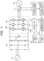
- FIG. 1 is a block diagram of examples of a power converter and an alternating-current motor 105 according to the embodiment.
- the power converter according to the embodiment is configured of a direct current converting unit 102, a smoothing capacitor 103, an electric power converting unit 104, a display unit 106, a control unit 107, a storage unit 108, an overexcitation determining unit 109, an electric current detector 110, an electric current detecting unit 111, and an electric current converting unit 112.
- a three-phase alternating-current power supply to which a three-phase alternating-current voltage is supplied from a power company, or an alternating-current voltage is supplied from a power generator, for example, and the three-phase alternating-current power supply inputs an alternating-current voltage to the direct current converting unit 102.
- the direct current converting unit 102 is configured of a diode circuit and a converter circuit using an IGBT and a flywheel diode, for example.
- the direct current converting unit 102 converts the alternating-current voltage inputted from the three-phase alternating-current power supply 101 into a direct-current voltage, and outputs the direct-current voltage to the smoothing capacitor 103.
- a converter configured of diodes is illustrated.
- the smoothing capacitor 103 smooths the direct-current voltage inputted from the direct current converting unit 102, and outputs the smoothed direct-current voltage to the electric power converting unit 104.
- a direct-current voltage may be directly inputted from the power generator to the smoothing capacitor 103 as the direct current converting unit 102 is omitted.
- the electric power converting unit 104 is configured of a switching circuit including an upper arm 104a and a lower arm 104b using an IGBT and a flywheel diode, for example.
- the electric power converting unit 104 receives the direct-current voltage of the smoothing capacitor 103 and a voltage instruction instructed from the control unit 107, converts the direct-current voltage into an alternating-current voltage, and outputs the alternating-current voltage to the alternating-current motor 105 for driving the alternating-current motor 105.
- the display unit 106 is configured of an I/O device such as an operator, for example.
- the display unit 106 receives overexcitation determination information from the overexcitation determining unit 109, determines the information, and displays a warning to the outside.
- the display unit 106 outputs manipulated setting data, for example, to the storage unit 108, and operation instruction information, for example, to the control unit 107.
- the storage unit 108 is configured of a non-volatile memory, for example, and stores the specified current value set using the I/O device of the display unit 106 and setting information that determines the control operation of the power converter after detecting overexcitation.
- the electric current detector 110 is configured of a hole CT and a shunt resistor, for example.
- the electric current detector 110 detects an electric current carried from the electric power converting unit 104 to the alternating-current motor 105, and outputs the electric current as a detected electric current value to the electric current detecting unit 111.
- the electric current detector 110 may be disposed at any position as long as the electric current detector 110 is disposed at a position at which a three-phase output electric current can be estimated or directly detected. In Fig. 1 , an exemplary position is illustrated at which an electric current carried through the alternating-current motor 105 is directly detected.
- the electric current detecting unit 111 acquires the detected electric current value inputted from the electric current detector 110 as a three-phase alternating-current electric current, for example, and outputs the detected electric current value to the electric current converting unit 112.
- the electric current converting unit 112 converts three-phase alternating-current electric currents i u , i v , and i w from the electric current detecting unit 111 into a two-axes fixed coordinate system (i ⁇ , i ⁇ ) using (Equation 1).
- the electric current converting unit 112 converts the fixed coordinate system into a rotating coordinate system (i d , i q ) using (Equation 2).
- the excitation current i d contributing to the excitation of the motor and the torque current i q contributing to the torque of the motor can be detected.
- the overexcitation determining unit 109 receives the setting information stored on the storage unit 108 and electric current information obtained by conversion at the electric current converting unit 112, determines whether the alternating-current motor 105 is overexcited, and outputs overexcitation determination information to the display unit 106 and the control unit 107.
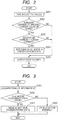
- the specific method will be described for individual Steps (S) with reference to a flowchart in Fig. 2 .
- the overexcitation determining unit 109 takes in the excitation current (i d ), the torque current (i q ), and the primary current (i 1 ) as electric values outputted from the electric current converting unit 112 (Step S201). Subsequently, the overexcitation determining unit 109 compares the specified current value preset on the storage unit 108 with the primary current (i 1 ) (Step S202).
- the specified current value preset on the storage unit 108 is an electric current set value, for example, provided for heat protection, which is 80% of the rated electric current of the motor, for example.
- the overexcitation determining unit 109 compares the excitation current (i d ) with the torque current (i q ) (Step S203). When the excitation current is greater than the torque current, the overexcitation determining unit 109 determines that the motor is in an overexcitation state (Step S204).
- preset parameters may be used, not comparison with the torque current. In this case, for example, it may be fine that an excitation current 1.5 times the excitation current value under the unloaded condition for the motor is set as a set value and overexcitation is determined in the case where the excitation current (i d ) exceeds this set value.
- the overexcitation determining unit 109 outputs the determined overexcitation determination information to the display unit 106 and the control unit 107 (Step S205). It is noted that at this time, the overexcitation determining unit 109 becomes unstable in the operation when returned from the overexcitation state to the normal excitation state in the case where the motor is temporarily turned into the overexcitation state and again returned into the normal state. In order to prevent the unsuitability, time interval characteristics may be provided for the transition of the excitation state.
- overexcitation is determined through two steps in Step S202 and Step S203.
- Step S202 it is determined whether the primary current (i 1 ) including the excitation current and the torque current is greater than the specified value.
- the process goes to Step S203 because the motor is possibly overexcited, whereas in the case where the primary current (i 1 ) is smaller than the specified value, the process goes to Step S205 because it is determined that the motor is normally excited.
- the case where the primary current is smaller than the specified value means the case where the torque current is small because a load is small and the excitation current is mostly occupied, for example.
- the excitation current is compared with the torque current. It is determined that the motor is overexcited in the case where the excitation current is greater than the torque current, whereas it is determined that the motor is normally excited in the opposite case. Namely, even though it is determined that the primary current (i 1 ) is greater than the specified value in Step S202, it is determined that the motor is normally excited in the case where the cause is an increase in the torque current in association with an increase in a load, whereas it is determined that the motor is overexcited only in the case where the excitation current is greater than the torque current. In other words, it is determined that the motor is overexcited only in the case where the excitation current is excessively carried through the motor with no necessity, so that overexcitation can be accurately determined. Moreover, the configuration of determining overexcitation can be easily configured.
- the control unit 107 receives setting information stored on the storage unit 108 in presetting and overexcitation determination information at the overexcitation determining unit 109 as inputs, determines the control operation of the power converter later, and outputs PWM control information to the electric power converting unit 104.
- the control unit 107 acquires setting information that is set on the storage unit 108 to determine the control operation of the power converter when overexcitation is detected and overexcitation information from the overexcitation determining unit 109 (Step S301).
- the control unit 107 determines whether the acquired items of information express the overexcitation state (Step S302). In the case where the information expresses overexcitation, the control unit 107 selects setting information to suppress overexcitation from items of setting information stored on the storage unit 108, and gives a PWM control signal to the electric power converting unit 104.
- the electric power converting unit 104 is controlled by the PWM control signal, and is controlled on the output to be supplied to the alternating-current motor 105 so as to suppress overexcitation (drive in the overexcitation state) (Step S303). In the case where the information does not express the overexcitation state, the motor is continued in normal drive (Step S304). Moreover, the overexcitation state is displayed on the display unit 106 to give a warning as one of the control operations.
- Step S302 in the determination whether the motor is in the overexcitation state, it is determined that the motor is in the overexcitation state in the case where it is determined that the motor is overexcited for three times, for example, as the result of a plurality of determinations.
- Fig. 4 illustrates the manner of one phase of voltage pulse instructions given from the control unit 107 to the electric power converting unit 104.
- the control unit 107 outputs a PWM control signal added with dead time as a control signal for the electric power converting unit 104 in order to prevent an upper arm 104a and a lower arm 104b of the switching circuit from short-circuiting. More specifically, in the case where the overexcitation determining unit 109 determines that the motor is overexcited, the control unit 107 makes dead time set for preventing the upper arm and the lower arm from short-circuiting to be the minimum value, adds a dead time instruction value to dead time, and varies (increases) dead time based on overexcitation determination information from the overexcitation determining unit.
- the pulse duration of the PWM control signal is reduced, and it is made possible to suppress the output voltage outputted from the electric power converting unit 104 to the alternating-current motor 105 and an electric current carried through the alternating-current motor 105.
- dead time is immediately set at 10 ⁇ s or dead time is gradually brought close to 10 ⁇ s when the alternating-current motor 105 is overexcited in the case where the minimum dead time is defined as 3 ⁇ s and the variable range is 10 ⁇ s, for example.
- the similar thing is applied in the process of returning dead time to the minimum value when the alternating-current motor 105 is returned from the overexcitation state.
- dead time is increased as linked to the amount of the primary current or the excitation current exceeding the specified current value in varying dead time.
- the control unit 107 controls the output voltage to the alternating-current motor 105 to continue the operation.
- the excitation voltage instruction is supplied from the control unit 107 to the electric power converting unit 104 in order to control the output voltage of the electric power converting unit 104, the excitation voltage instruction is used for control.
- the control unit 107 controls the correction of the excitation voltage instruction in the direction in which the output voltage of the electric power converting unit 104 is reduced based on overexcitation determination information from the overexcitation determining unit, and continues the operation of the alternating-current motor 105.
- the correction control for example, in the case where the excitation current reaches the specified current value or more for overexcitation, the control unit 107 performs PI control in the direction in which the excitation voltage instruction is reduced (in the negative direction) as the specified current value is a target value.
- control for an example of stopping the operation, in the case where the motor is turned into the overexcitation state, such control is performed in which the alternating-current motor 105 is reduced in speed and stopped by the instruction from the control unit 107 or in which the output of the electric power converting unit 104 is interrupted.
- the motor is overexcited because a parameter for use in control is inappropreately set, for example, in controlling the alternating-current motor 105 by the control unit 107, the alternating-current motor 105 is stopped and a warning for an overexcitation state is issued, because of association with changes in the settings of the parameters.
- This control is necessary in the case where overexcitation occurs when an unexpected motor is connected, not a standard motor.
- an electric current converting unit 112 converts a three-phase alternating-current electric current inputted from an electric current detecting unit 111 into a two-axes fixed coordinate system using (Equation 1) described above, and converts the two-axes fixed coordinate system into a rotating coordinate system using (Equation 2).
- the excitation current contributing to the excitation of a motor and the torque current contributing to the torque of the motor can be detected.
- the primary electric current carried through an alternating-current motor 105 is found from the converted excitation current and the converted torque current using (Equation 3).
- An overexcitation determining unit 109 receives setting information stored on the storage unit 108, electric current information obtained from conversion at the electric current converting unit 112, and an excitation current instruction computed at a control unit 107, determines whether the alternating-current motor 105 is overexcited, and outputs the determination information to a display unit 106 and the control unit 107.
- the specific control will be described with reference to Fig. 5 .
- the overexcitation determining unit 109 takes in the excitation current value (the detected excitation current) outputted from the electric current converting unit 112 and the excitation current instruction (the excitation current comparison value) computed at the control unit 107 (S501). Subsequently, the overexcitation determining unit 109 compares the detected excitation current with the computed excitation current comparison value (S502).
- the excitation current comparison value at this time is a value calculated from the value of a standard excitation current instruction of a motor, which is supposed to be 150% of the value of the excitation current instruction under an unloaded condition, for example.
- the excitation current value outputted from the electric current converting unit 112 is compared with the excitation current instruction (the excitation current comparison value) computed at the control unit 107, and overexcitation is determined.
- the excitation currents are directly compared, so that overexcitation can be determined in a more accurate, simpler configuration.
- the overexcitation determining unit 109 determines that the motor is in the overexcitation state when the excitation current value is greater than the excitation current comparison value (S503).
- the overexcitation determining unit 109 outputs the determined overexcitation information to the display unit 106 and the control unit 107 (S504). At this time, the overexcitation determining unit 109 becomes unstable in the operation when returned from the overexcitation state to the normal excitation state in the case where the motor is temporarily turned into the overexcitation state and again returned into the normal state.
- the PWM control signal from the control unit 107 to the electric power converting unit 104 is controlled to continue the operation while controlling the output pulse from the electric power converting unit 104 to the alternating-current motor 105.
- the pulse duration is controlled as illustrated in Fig. 4 , so that the output voltage outputted from the electric power converting unit 104 to the alternating-current motor 105 and an electric current carried through the alternating-current motor 105 can be suppressed.
- control is performed as similar to the first embodiment for another example in which in the case where the motor is turned into the overexcitation state, the operation of the motor is continued while the control unit 107 controls the output voltage to the alternating-current motor 105. Furthermore, for an example of stopping the operation, the control unit 107 reduces the speed and stops the alternating-current motor 105 or interrupts the output of the electric power converting unit in the case where the motor is turned into the overexcitation state.
- the alternating-current motor 105 is stopped and a warning of the overexcitation state is issued in association with changes in the settings of the parameters.
- the present invention is not limited to the foregoing embodiments, and includes various exemplary modifications.
- the foregoing embodiments are described in detail for easily understanding the present invention, and the present invention is not necessarily limited to ones including all of the described configurations.
- the functions, the processing units, and the processing modules are implemented by hardware as by designing them using an integrated circuit, for example.
- the foregoing configurations and the functions are implemented by software in which a processor interprets programs to implement and execute the functions.
- Information such as programs, tables, and files to implement the functions can be placed on a recording device such as a memory, a hard disk, and an SSD (SOLID STATE DRIVE) or on a recording medium such as an IC card, an SD card, and a DVD.
- control lines and information lines are illustrated, which are considered to be necessary for explanation, and all of the control lines and the information lines of a product are not always illustrated.
Landscapes
- Engineering & Computer Science (AREA)
- Power Engineering (AREA)
- Control Of Ac Motors In General (AREA)
Applications Claiming Priority (2)
| Application Number | Priority Date | Filing Date | Title |
|---|---|---|---|
| JP2011160384A JP5659330B2 (ja) | 2011-07-22 | 2011-07-22 | 電力変換装置 |
| PCT/JP2012/063681 WO2013015010A1 (ja) | 2011-07-22 | 2012-05-28 | 電力変換装置 |
Publications (3)
| Publication Number | Publication Date |
|---|---|
| EP2736165A1 EP2736165A1 (en) | 2014-05-28 |
| EP2736165A4 EP2736165A4 (en) | 2015-10-28 |
| EP2736165B1 true EP2736165B1 (en) | 2020-04-08 |
Family
ID=47600870
Family Applications (1)
| Application Number | Title | Priority Date | Filing Date |
|---|---|---|---|
| EP12817332.5A Active EP2736165B1 (en) | 2011-07-22 | 2012-05-28 | Power converter |
Country Status (4)
| Country | Link |
|---|---|
| EP (1) | EP2736165B1 (ja) |
| JP (1) | JP5659330B2 (ja) |
| CN (1) | CN103650334B (ja) |
| WO (1) | WO2013015010A1 (ja) |
Families Citing this family (2)
| Publication number | Priority date | Publication date | Assignee | Title |
|---|---|---|---|---|
| CN107565515B (zh) * | 2017-08-17 | 2019-05-21 | 国家电网公司 | 一种采用角度补偿电压幅值的变压器过激磁保护方法 |
| WO2019111395A1 (ja) * | 2017-12-07 | 2019-06-13 | 株式会社日立産機システム | 電力変換装置、モータ制御システム、及び、そのパラメータ設定方法 |
Family Cites Families (11)
| Publication number | Priority date | Publication date | Assignee | Title |
|---|---|---|---|---|
| JP3226253B2 (ja) * | 1995-09-11 | 2001-11-05 | 株式会社東芝 | 永久磁石同期電動機の制御装置 |
| JPH1118496A (ja) * | 1997-06-18 | 1999-01-22 | Hitachi Ltd | 電気車の制御装置および制御方法 |
| JP2001218500A (ja) * | 2000-01-31 | 2001-08-10 | Sumitomo Heavy Ind Ltd | 誘導電動機の省エネルギー運転方法 |
| JP2002186293A (ja) * | 2000-12-12 | 2002-06-28 | Kokusan Denki Co Ltd | 内燃機関用回転電機の制御装置 |
| JP3918148B2 (ja) * | 2001-07-24 | 2007-05-23 | 株式会社日立製作所 | インバータ装置 |
| KR100442494B1 (ko) * | 2002-02-26 | 2004-07-30 | 엘지산전 주식회사 | 인버터의 토오크 제어장치 및 방법 |
| JP4223880B2 (ja) * | 2003-07-31 | 2009-02-12 | トヨタ自動車株式会社 | モータ駆動装置 |
| JP4455075B2 (ja) * | 2004-01-28 | 2010-04-21 | 三菱電機株式会社 | モータ制御装置 |
| JP2008172949A (ja) * | 2007-01-12 | 2008-07-24 | Yaskawa Electric Corp | 電力変換装置及びその電動機保護方法 |
| WO2009038047A1 (ja) * | 2007-09-18 | 2009-03-26 | Kabushiki Kaisha Toshiba | 可変磁束ドライブシステム |
| DE102009021823A1 (de) * | 2009-05-18 | 2010-12-09 | Bombardier Transportation Gmbh | Überstrombegrenzung bei der Regelung von stromrichtergespeisten Drehstrommaschinen |
-
2011
- 2011-07-22 JP JP2011160384A patent/JP5659330B2/ja not_active Expired - Fee Related
-
2012
- 2012-05-28 WO PCT/JP2012/063681 patent/WO2013015010A1/ja active Application Filing
- 2012-05-28 EP EP12817332.5A patent/EP2736165B1/en active Active
- 2012-05-28 CN CN201280035185.9A patent/CN103650334B/zh not_active Expired - Fee Related
Non-Patent Citations (1)
| Title |
|---|
| None * |
Also Published As
| Publication number | Publication date |
|---|---|
| JP2013027179A (ja) | 2013-02-04 |
| EP2736165A4 (en) | 2015-10-28 |
| CN103650334A (zh) | 2014-03-19 |
| WO2013015010A1 (ja) | 2013-01-31 |
| CN103650334B (zh) | 2016-06-22 |
| EP2736165A1 (en) | 2014-05-28 |
| JP5659330B2 (ja) | 2015-01-28 |
Similar Documents
| Publication | Publication Date | Title |
|---|---|---|
| CN111245323B (zh) | 电机控制方法、装置和计算机可读存储介质、电器设备 | |
| US8264209B2 (en) | Method of and apparatus for operating a double-fed asynchronous machine in the event of transient mains voltage changes | |
| KR101958120B1 (ko) | 전동기의 제어 장치 및 제어 방법 | |
| US9054617B2 (en) | Control device of permanent magnet synchronous motor for preventing irreversible demagnetization of permanent magnet and control system including the same | |
| EP2827493B1 (en) | Device for controlling electric motor and method for controlling electric motor | |
| JP5274236B2 (ja) | 3相インバータの電源回路保護装置 | |
| US9595908B2 (en) | Power converter | |
| US20150263661A1 (en) | System and method for controlling regenerating energy in an adjustable speed drive | |
| US10396702B2 (en) | Motor drive control device | |
| JP2007318894A (ja) | 同期モーター用磁極位置センサーの位相ズレ検出装置および検出方法 | |
| EP2958223A1 (en) | Power-conversion device and method for controlling same | |
| KR20140141503A (ko) | 모터 제어 장치 및 그것을 구비한 건설 기계 | |
| US20160380576A1 (en) | Control device | |
| EP3767819B1 (en) | Motor control method and motor control device | |
| EP3641125B1 (en) | Control device for power tool | |
| EP2736165B1 (en) | Power converter | |
| EP3719989A1 (en) | Electric machine controlling method and electric machine controlling device | |
| JP2010098868A (ja) | モータ駆動制御装置 | |
| EP2618480A2 (en) | Motor control device and air conditioner | |
| EP3340459B1 (en) | Method for controlling inverter | |
| US12021469B2 (en) | Rotating machine control device | |
| CN116027240A (zh) | 电动机控制装置及用于电动机控制装置中设置的电流检测器的异常检测方法 | |
| JP2014036539A (ja) | インバータ装置及びインバータ装置のスイッチングタイミング補正方法 | |
| US20160352274A1 (en) | System of controlling induction electric motor | |
| US11296625B2 (en) | Control device and control method for synchronous electric motor |
Legal Events
| Date | Code | Title | Description |
|---|---|---|---|
| PUAI | Public reference made under article 153(3) epc to a published international application that has entered the european phase |
Free format text: ORIGINAL CODE: 0009012 |
|
| 17P | Request for examination filed |
Effective date: 20140109 |
|
| AK | Designated contracting states |
Kind code of ref document: A1 Designated state(s): AL AT BE BG CH CY CZ DE DK EE ES FI FR GB GR HR HU IE IS IT LI LT LU LV MC MK MT NL NO PL PT RO RS SE SI SK SM TR |
|
| DAX | Request for extension of the european patent (deleted) | ||
| RA4 | Supplementary search report drawn up and despatched (corrected) |
Effective date: 20150930 |
|
| RIC1 | Information provided on ipc code assigned before grant |
Ipc: H02P 21/00 20060101ALI20150924BHEP Ipc: H02P 29/02 20060101ALI20150924BHEP Ipc: H02P 23/14 20060101ALI20150924BHEP Ipc: H02P 27/04 20060101ALI20150924BHEP Ipc: H02P 27/06 20060101AFI20150924BHEP |
|
| REG | Reference to a national code |
Ref country code: DE Ref legal event code: R079 Ref document number: 602012069172 Country of ref document: DE Free format text: PREVIOUS MAIN CLASS: H02P0027060000 Ipc: H02P0029024000 |
|
| GRAP | Despatch of communication of intention to grant a patent |
Free format text: ORIGINAL CODE: EPIDOSNIGR1 |
|
| STAA | Information on the status of an ep patent application or granted ep patent |
Free format text: STATUS: GRANT OF PATENT IS INTENDED |
|
| RIC1 | Information provided on ipc code assigned before grant |
Ipc: H02P 29/024 20160101AFI20190923BHEP Ipc: H02P 29/032 20160101ALI20190923BHEP Ipc: H02P 21/00 20160101ALI20190923BHEP Ipc: H02P 23/14 20060101ALI20190923BHEP |
|
| INTG | Intention to grant announced |
Effective date: 20191023 |
|
| GRAS | Grant fee paid |
Free format text: ORIGINAL CODE: EPIDOSNIGR3 |
|
| GRAA | (expected) grant |
Free format text: ORIGINAL CODE: 0009210 |
|
| STAA | Information on the status of an ep patent application or granted ep patent |
Free format text: STATUS: THE PATENT HAS BEEN GRANTED |
|
| AK | Designated contracting states |
Kind code of ref document: B1 Designated state(s): AL AT BE BG CH CY CZ DE DK EE ES FI FR GB GR HR HU IE IS IT LI LT LU LV MC MK MT NL NO PL PT RO RS SE SI SK SM TR |
|
| REG | Reference to a national code |
Ref country code: GB Ref legal event code: FG4D |
|
| REG | Reference to a national code |
Ref country code: CH Ref legal event code: EP Ref country code: AT Ref legal event code: REF Ref document number: 1255723 Country of ref document: AT Kind code of ref document: T Effective date: 20200415 |
|
| REG | Reference to a national code |
Ref country code: DE Ref legal event code: R096 Ref document number: 602012069172 Country of ref document: DE |
|
| REG | Reference to a national code |
Ref country code: IE Ref legal event code: FG4D |
|
| REG | Reference to a national code |
Ref country code: NL Ref legal event code: MP Effective date: 20200408 |
|
| REG | Reference to a national code |
Ref country code: LT Ref legal event code: MG4D |
|
| PG25 | Lapsed in a contracting state [announced via postgrant information from national office to epo] |
Ref country code: IS Free format text: LAPSE BECAUSE OF FAILURE TO SUBMIT A TRANSLATION OF THE DESCRIPTION OR TO PAY THE FEE WITHIN THE PRESCRIBED TIME-LIMIT Effective date: 20200808 Ref country code: PT Free format text: LAPSE BECAUSE OF FAILURE TO SUBMIT A TRANSLATION OF THE DESCRIPTION OR TO PAY THE FEE WITHIN THE PRESCRIBED TIME-LIMIT Effective date: 20200817 Ref country code: NO Free format text: LAPSE BECAUSE OF FAILURE TO SUBMIT A TRANSLATION OF THE DESCRIPTION OR TO PAY THE FEE WITHIN THE PRESCRIBED TIME-LIMIT Effective date: 20200708 Ref country code: GR Free format text: LAPSE BECAUSE OF FAILURE TO SUBMIT A TRANSLATION OF THE DESCRIPTION OR TO PAY THE FEE WITHIN THE PRESCRIBED TIME-LIMIT Effective date: 20200709 Ref country code: LT Free format text: LAPSE BECAUSE OF FAILURE TO SUBMIT A TRANSLATION OF THE DESCRIPTION OR TO PAY THE FEE WITHIN THE PRESCRIBED TIME-LIMIT Effective date: 20200408 Ref country code: SE Free format text: LAPSE BECAUSE OF FAILURE TO SUBMIT A TRANSLATION OF THE DESCRIPTION OR TO PAY THE FEE WITHIN THE PRESCRIBED TIME-LIMIT Effective date: 20200408 Ref country code: NL Free format text: LAPSE BECAUSE OF FAILURE TO SUBMIT A TRANSLATION OF THE DESCRIPTION OR TO PAY THE FEE WITHIN THE PRESCRIBED TIME-LIMIT Effective date: 20200408 Ref country code: FI Free format text: LAPSE BECAUSE OF FAILURE TO SUBMIT A TRANSLATION OF THE DESCRIPTION OR TO PAY THE FEE WITHIN THE PRESCRIBED TIME-LIMIT Effective date: 20200408 |
|
| REG | Reference to a national code |
Ref country code: AT Ref legal event code: MK05 Ref document number: 1255723 Country of ref document: AT Kind code of ref document: T Effective date: 20200408 |
|
| PG25 | Lapsed in a contracting state [announced via postgrant information from national office to epo] |
Ref country code: BG Free format text: LAPSE BECAUSE OF FAILURE TO SUBMIT A TRANSLATION OF THE DESCRIPTION OR TO PAY THE FEE WITHIN THE PRESCRIBED TIME-LIMIT Effective date: 20200708 Ref country code: HR Free format text: LAPSE BECAUSE OF FAILURE TO SUBMIT A TRANSLATION OF THE DESCRIPTION OR TO PAY THE FEE WITHIN THE PRESCRIBED TIME-LIMIT Effective date: 20200408 Ref country code: LV Free format text: LAPSE BECAUSE OF FAILURE TO SUBMIT A TRANSLATION OF THE DESCRIPTION OR TO PAY THE FEE WITHIN THE PRESCRIBED TIME-LIMIT Effective date: 20200408 Ref country code: RS Free format text: LAPSE BECAUSE OF FAILURE TO SUBMIT A TRANSLATION OF THE DESCRIPTION OR TO PAY THE FEE WITHIN THE PRESCRIBED TIME-LIMIT Effective date: 20200408 |
|
| PG25 | Lapsed in a contracting state [announced via postgrant information from national office to epo] |
Ref country code: AL Free format text: LAPSE BECAUSE OF FAILURE TO SUBMIT A TRANSLATION OF THE DESCRIPTION OR TO PAY THE FEE WITHIN THE PRESCRIBED TIME-LIMIT Effective date: 20200408 |
|
| REG | Reference to a national code |
Ref country code: DE Ref legal event code: R097 Ref document number: 602012069172 Country of ref document: DE |
|
| PG25 | Lapsed in a contracting state [announced via postgrant information from national office to epo] |
Ref country code: AT Free format text: LAPSE BECAUSE OF FAILURE TO SUBMIT A TRANSLATION OF THE DESCRIPTION OR TO PAY THE FEE WITHIN THE PRESCRIBED TIME-LIMIT Effective date: 20200408 Ref country code: MC Free format text: LAPSE BECAUSE OF FAILURE TO SUBMIT A TRANSLATION OF THE DESCRIPTION OR TO PAY THE FEE WITHIN THE PRESCRIBED TIME-LIMIT Effective date: 20200408 Ref country code: ES Free format text: LAPSE BECAUSE OF FAILURE TO SUBMIT A TRANSLATION OF THE DESCRIPTION OR TO PAY THE FEE WITHIN THE PRESCRIBED TIME-LIMIT Effective date: 20200408 Ref country code: RO Free format text: LAPSE BECAUSE OF FAILURE TO SUBMIT A TRANSLATION OF THE DESCRIPTION OR TO PAY THE FEE WITHIN THE PRESCRIBED TIME-LIMIT Effective date: 20200408 Ref country code: CZ Free format text: LAPSE BECAUSE OF FAILURE TO SUBMIT A TRANSLATION OF THE DESCRIPTION OR TO PAY THE FEE WITHIN THE PRESCRIBED TIME-LIMIT Effective date: 20200408 Ref country code: CH Free format text: LAPSE BECAUSE OF NON-PAYMENT OF DUE FEES Effective date: 20200531 Ref country code: EE Free format text: LAPSE BECAUSE OF FAILURE TO SUBMIT A TRANSLATION OF THE DESCRIPTION OR TO PAY THE FEE WITHIN THE PRESCRIBED TIME-LIMIT Effective date: 20200408 Ref country code: SM Free format text: LAPSE BECAUSE OF FAILURE TO SUBMIT A TRANSLATION OF THE DESCRIPTION OR TO PAY THE FEE WITHIN THE PRESCRIBED TIME-LIMIT Effective date: 20200408 Ref country code: DK Free format text: LAPSE BECAUSE OF FAILURE TO SUBMIT A TRANSLATION OF THE DESCRIPTION OR TO PAY THE FEE WITHIN THE PRESCRIBED TIME-LIMIT Effective date: 20200408 Ref country code: LI Free format text: LAPSE BECAUSE OF NON-PAYMENT OF DUE FEES Effective date: 20200531 |
|
| PLBE | No opposition filed within time limit |
Free format text: ORIGINAL CODE: 0009261 |
|
| STAA | Information on the status of an ep patent application or granted ep patent |
Free format text: STATUS: NO OPPOSITION FILED WITHIN TIME LIMIT |
|
| PG25 | Lapsed in a contracting state [announced via postgrant information from national office to epo] |
Ref country code: SK Free format text: LAPSE BECAUSE OF FAILURE TO SUBMIT A TRANSLATION OF THE DESCRIPTION OR TO PAY THE FEE WITHIN THE PRESCRIBED TIME-LIMIT Effective date: 20200408 Ref country code: PL Free format text: LAPSE BECAUSE OF FAILURE TO SUBMIT A TRANSLATION OF THE DESCRIPTION OR TO PAY THE FEE WITHIN THE PRESCRIBED TIME-LIMIT Effective date: 20200408 |
|
| 26N | No opposition filed |
Effective date: 20210112 |
|
| REG | Reference to a national code |
Ref country code: BE Ref legal event code: MM Effective date: 20200531 |
|
| GBPC | Gb: european patent ceased through non-payment of renewal fee |
Effective date: 20200708 |
|
| PG25 | Lapsed in a contracting state [announced via postgrant information from national office to epo] |
Ref country code: LU Free format text: LAPSE BECAUSE OF NON-PAYMENT OF DUE FEES Effective date: 20200528 |
|
| PG25 | Lapsed in a contracting state [announced via postgrant information from national office to epo] |
Ref country code: IE Free format text: LAPSE BECAUSE OF NON-PAYMENT OF DUE FEES Effective date: 20200528 Ref country code: GB Free format text: LAPSE BECAUSE OF NON-PAYMENT OF DUE FEES Effective date: 20200708 |
|
| PG25 | Lapsed in a contracting state [announced via postgrant information from national office to epo] |
Ref country code: BE Free format text: LAPSE BECAUSE OF NON-PAYMENT OF DUE FEES Effective date: 20200531 Ref country code: SI Free format text: LAPSE BECAUSE OF FAILURE TO SUBMIT A TRANSLATION OF THE DESCRIPTION OR TO PAY THE FEE WITHIN THE PRESCRIBED TIME-LIMIT Effective date: 20200408 |
|
| PG25 | Lapsed in a contracting state [announced via postgrant information from national office to epo] |
Ref country code: TR Free format text: LAPSE BECAUSE OF FAILURE TO SUBMIT A TRANSLATION OF THE DESCRIPTION OR TO PAY THE FEE WITHIN THE PRESCRIBED TIME-LIMIT Effective date: 20200408 Ref country code: MT Free format text: LAPSE BECAUSE OF FAILURE TO SUBMIT A TRANSLATION OF THE DESCRIPTION OR TO PAY THE FEE WITHIN THE PRESCRIBED TIME-LIMIT Effective date: 20200408 Ref country code: CY Free format text: LAPSE BECAUSE OF FAILURE TO SUBMIT A TRANSLATION OF THE DESCRIPTION OR TO PAY THE FEE WITHIN THE PRESCRIBED TIME-LIMIT Effective date: 20200408 |
|
| PG25 | Lapsed in a contracting state [announced via postgrant information from national office to epo] |
Ref country code: MK Free format text: LAPSE BECAUSE OF FAILURE TO SUBMIT A TRANSLATION OF THE DESCRIPTION OR TO PAY THE FEE WITHIN THE PRESCRIBED TIME-LIMIT Effective date: 20200408 |
|
| PGFP | Annual fee paid to national office [announced via postgrant information from national office to epo] |
Ref country code: IT Payment date: 20220412 Year of fee payment: 11 Ref country code: FR Payment date: 20220408 Year of fee payment: 11 Ref country code: DE Payment date: 20220406 Year of fee payment: 11 |
|
| REG | Reference to a national code |
Ref country code: DE Ref legal event code: R119 Ref document number: 602012069172 Country of ref document: DE |
|
| PG25 | Lapsed in a contracting state [announced via postgrant information from national office to epo] |
Ref country code: IT Free format text: LAPSE BECAUSE OF NON-PAYMENT OF DUE FEES Effective date: 20230528 Ref country code: DE Free format text: LAPSE BECAUSE OF NON-PAYMENT OF DUE FEES Effective date: 20231201 |
|
| PG25 | Lapsed in a contracting state [announced via postgrant information from national office to epo] |
Ref country code: FR Free format text: LAPSE BECAUSE OF NON-PAYMENT OF DUE FEES Effective date: 20230531 |