EP2736162A2 - Procédé et appareil permettant de maximiser le rendement énergétique d'un système d'entraînement électrique - Google Patents
Procédé et appareil permettant de maximiser le rendement énergétique d'un système d'entraînement électrique Download PDFInfo
- Publication number
- EP2736162A2 EP2736162A2 EP13193407.7A EP13193407A EP2736162A2 EP 2736162 A2 EP2736162 A2 EP 2736162A2 EP 13193407 A EP13193407 A EP 13193407A EP 2736162 A2 EP2736162 A2 EP 2736162A2
- Authority
- EP
- European Patent Office
- Prior art keywords
- torque
- motor
- basis
- parameter
- rotational speed
- Prior art date
- Legal status (The legal status is an assumption and is not a legal conclusion. Google has not performed a legal analysis and makes no representation as to the accuracy of the status listed.)
- Granted
Links
Images

Classifications
-
- B—PERFORMING OPERATIONS; TRANSPORTING
- B60—VEHICLES IN GENERAL
- B60L—PROPULSION OF ELECTRICALLY-PROPELLED VEHICLES; SUPPLYING ELECTRIC POWER FOR AUXILIARY EQUIPMENT OF ELECTRICALLY-PROPELLED VEHICLES; ELECTRODYNAMIC BRAKE SYSTEMS FOR VEHICLES IN GENERAL; MAGNETIC SUSPENSION OR LEVITATION FOR VEHICLES; MONITORING OPERATING VARIABLES OF ELECTRICALLY-PROPELLED VEHICLES; ELECTRIC SAFETY DEVICES FOR ELECTRICALLY-PROPELLED VEHICLES
- B60L15/00—Methods, circuits, or devices for controlling the traction-motor speed of electrically-propelled vehicles
- B60L15/20—Methods, circuits, or devices for controlling the traction-motor speed of electrically-propelled vehicles for control of the vehicle or its driving motor to achieve a desired performance, e.g. speed, torque, programmed variation of speed
-
- H—ELECTRICITY
- H02—GENERATION; CONVERSION OR DISTRIBUTION OF ELECTRIC POWER
- H02P—CONTROL OR REGULATION OF ELECTRIC MOTORS, ELECTRIC GENERATORS OR DYNAMO-ELECTRIC CONVERTERS; CONTROLLING TRANSFORMERS, REACTORS OR CHOKE COILS
- H02P6/00—Arrangements for controlling synchronous motors or other dynamo-electric motors using electronic commutation dependent on the rotor position; Electronic commutators therefor
-
- H—ELECTRICITY
- H02—GENERATION; CONVERSION OR DISTRIBUTION OF ELECTRIC POWER
- H02P—CONTROL OR REGULATION OF ELECTRIC MOTORS, ELECTRIC GENERATORS OR DYNAMO-ELECTRIC CONVERTERS; CONTROLLING TRANSFORMERS, REACTORS OR CHOKE COILS
- H02P23/00—Arrangements or methods for the control of AC motors characterised by a control method other than vector control
- H02P23/0004—Control strategies in general, e.g. linear type, e.g. P, PI, PID, using robust control
-
- H—ELECTRICITY
- H02—GENERATION; CONVERSION OR DISTRIBUTION OF ELECTRIC POWER
- H02P—CONTROL OR REGULATION OF ELECTRIC MOTORS, ELECTRIC GENERATORS OR DYNAMO-ELECTRIC CONVERTERS; CONTROLLING TRANSFORMERS, REACTORS OR CHOKE COILS
- H02P27/00—Arrangements or methods for the control of AC motors characterised by the kind of supply voltage
- H02P27/04—Arrangements or methods for the control of AC motors characterised by the kind of supply voltage using variable-frequency supply voltage, e.g. inverter or converter supply voltage
-
- Y—GENERAL TAGGING OF NEW TECHNOLOGICAL DEVELOPMENTS; GENERAL TAGGING OF CROSS-SECTIONAL TECHNOLOGIES SPANNING OVER SEVERAL SECTIONS OF THE IPC; TECHNICAL SUBJECTS COVERED BY FORMER USPC CROSS-REFERENCE ART COLLECTIONS [XRACs] AND DIGESTS
- Y02—TECHNOLOGIES OR APPLICATIONS FOR MITIGATION OR ADAPTATION AGAINST CLIMATE CHANGE
- Y02P—CLIMATE CHANGE MITIGATION TECHNOLOGIES IN THE PRODUCTION OR PROCESSING OF GOODS
- Y02P80/00—Climate change mitigation technologies for sector-wide applications
- Y02P80/10—Efficient use of energy, e.g. using compressed air or pressurized fluid as energy carrier
-
- Y—GENERAL TAGGING OF NEW TECHNOLOGICAL DEVELOPMENTS; GENERAL TAGGING OF CROSS-SECTIONAL TECHNOLOGIES SPANNING OVER SEVERAL SECTIONS OF THE IPC; TECHNICAL SUBJECTS COVERED BY FORMER USPC CROSS-REFERENCE ART COLLECTIONS [XRACs] AND DIGESTS
- Y02—TECHNOLOGIES OR APPLICATIONS FOR MITIGATION OR ADAPTATION AGAINST CLIMATE CHANGE
- Y02T—CLIMATE CHANGE MITIGATION TECHNOLOGIES RELATED TO TRANSPORTATION
- Y02T10/00—Road transport of goods or passengers
- Y02T10/60—Other road transportation technologies with climate change mitigation effect
- Y02T10/72—Electric energy management in electromobility
Definitions
- the present invention relates to electric drive systems, particularly to maximising energy efficiency of an electric drive system.
- Manufacturers of present-day frequency converters can utilise various techniques in controlling behaviour of a torque of a motor in respect to a rotational speed of the motor in an electric drive application.
- the applications can, for example, be divided into two groups on the basis of the behaviour of the load: linear torque/speed ratio applications and quadratic torque/speed ratio applications.
- linear (torque/speed ratio) applications the torque applied to the load is directly proportional to the rotational speed.
- quadratic (torque/speed ratio) applications the torque is proportional to the square of the rotational speed.
- one of the above approaches i.e. a more dynamic performance or a more economic performance, may be selected as the default performance approach, and the other may be selected by the user. The user does not, however, always select the more appropriate approach for the application in question.
- An object of the present invention is to provide a method and an apparatus for implementing the method so as to alleviate the above disadvantages.
- the objects of the invention are achieved by a method and an arrangement which are characterized by what is stated in the independent claims.
- the preferred embodiments of the invention are disclosed in the dependent claims.
- the disclosed method allows automatised selection of the operating mode, i.e. a dynamic performance mode where a nominal flux is used or an economic performance mode where the flux is limited in order to achieve energy savings.
- the disclosed method first gathers a set of data points of torques at different rotational speeds. Then, the method calculates with which behaviour of the load, i.e. the linear behaviour or the quadratic behaviour, the data points have better correlation. On the basis of the result of this calculation, one of the two torque/speed behaviours is selected to represent the torque characteristics of the system, and the motor is controlled on the basis of the selected behaviour. As the behaviour is automatically determined, selecting a more appropriate operating mode does not have to rely on user input.
- the present disclosure discloses a method for maximising energy efficiency of an electric drive system comprising an electric motor and a load.
- the disclosed method allows automatic detection of different behaviours of torque of the motor in respect to a rotational speed of the motor, i.e. detection of different torque/speed ratios.
- the torque characteristics of the system may be selected from two types of behaviour: linear behaviour and quadratic behaviour of the torque in respect to the rotational speed.
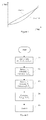
- Figure 1 illustrates the linear and quadratic system behaviour of a torque in respect to a rotational speed.
- the linear behaviour (dotted line) represents a situation where the torque T is directly proportional to the rotational speed f.
- T af + b , where a is a coefficient which represents the relation between the torque and the rotational speed, and b represents a constant torque which is independent from the rotational speed.
- a represents the relation between the torque and the rotational speed
- b represents a constant torque which is independent from the rotational speed.
- the disclosed method automatically determines torque characteristics of the system in question, i.e. which of Equations (1) and (2) better describes the system.
- the motor can then be controlled on the basis of the determined torque characteristics.
- Determining torque characteristics may, for example, comprise first determining the torque of the motor and the rotational speed of the motor.
- the torque and rotational speed may be directly measured, or they may also be estimated, for example, by a frequency converter controlling the motor. If information on how much power is supplied to the motor is available, the torque can be calculated from the power.
- the rotational speed may be determined from the output frequency of the frequency converter.
- the disclosed method may then gather a plurality of data points, where each data point represents the torque of the motor at a rotational speed of the motor.
- a value for a first parameter may be calculated.
- the first parameter represents how much the data points deviate from the quadratic behaviour.
- a value for a second parameter is also calculated on the basis of the data points.
- the second parameter represents how much the data points deviate from the linear behaviour. Then, the first parameter may be compared with the second parameter, and the torque characteristics may be determined on the basis of the comparison.
- the motor may be controlled on the basis of the determined torque characteristics.
- the operating mode i.e. the dynamic performance mode where the flux is not limited or the economic performance mode where the flux is limited in order to improve energy efficiency, can be chosen.
- determining the torque characteristics can also be accomplished by monitoring the rate of change of the torque reference or the difference between the torque reference and the actual torque.
- the magnitude of the rate of change of the torque reference may first be determined. The magnitude may then be compared with a set limit, and if the magnitude exceeds the set limit, the electric drive can be set to the dynamic performance mode.
- the torque of the motor may first be determined.
- the difference between the torque reference and the determined torque may then be determined and compared with a set limit. If the difference exceeds the set limit, the electric drive is set to the dynamic performance mode.
- Figure 2 illustrates a flowchart of an exemplary implementation of the disclosed method.
- the torque and the rotational speed are measured and data points are gathered.
- the value for a first parameter is calculated.
- Two equations are formed on the basis of two data points, for example ( T 1 , f 1 ) and ( T 2 , f 2 ).
- the torque is represented by the square of the rotational speed multiplied by a first coefficient and incremented by a second coefficient.
- a sq T 1 - T 2 f 1 2 - f 2 2
- b sq T 2 ⁇ f 1 2 - T 1 ⁇ f 2 2 f 1 2 - f 2 2 .
- an expected torque T 3 sq for the rotational speed in the third data may be calculated.
- T 3 ⁇ sq a sq ⁇ f 3 2 + b sq .
- the difference between the expected torque T 3 sq and the torque T 3 at the third data point may then be calculated, and the magnitude
- the value for a second parameter is calculated.
- Calculating the value for the second parameter in the third step 23 can be performed in a similar manner to that in the second step 22.
- Two equations are formed on the basis of two data points, for example ( T 1 , f 1 ) and ( T 2 , f 2 ).
- the torque is represented by the rotational speed multiplied by a first coefficient and incremented by a second coefficient.
- T 1 a lin ⁇ f 1 + b lin
- T 2 a lin ⁇ f 2 + b lin .
- the difference between the expected torque T 3 lin and the torque T 3 at the third data point may then be calculated, and the magnitude
- of the difference may be used as the value of the second parameter.
- the first parameter is compared with the second parameter and the torque characteristics of the system are determined on the basis of the comparison.
- the behaviour i.e the linear or quadratic torque/speed ratio, which better fits the data points may be selected as the system torque characteristics.
- Calculation of the first and the second parameter is not, however, limited to the above examples.
- the method of least squares may, for example, be used.
- the data points may be fitted to Equations (1) and (2) by using the method of least squares and the torque characteristics to be used may then be selected on the basis of the best fit.
- the method of least squares is computationally somewhat more complex than the three-point curve fitting as disclosed in Equations (3) to (12).
- FIG 3 illustrates an apparatus 31 for maximising energy efficiency of an electric drive system comprising an electric motor 32 and a load 33.
- the load 33 in Figure 3 is a fan which is rotated by the motor 32.
- the apparatus 31 in Figure 3 is a frequency converter which controls the motor 32 and implements the disclosed method.
- the frequency converter 31 automatically selects appropriate torque characteristics to be used, depending on the application.
- the torque characteristics in the frequency converter 31 may be selected from two types of behaviour: linear and quadratic behaviour of a torque of the motor in respect to a rotational speed of the motor.
- the frequency converter 31 acts as means for determining a torque of the motor and a rotational speed of the motor. In Figure 3 , it has internal estimates of said variables.
- the frequency converter 31 gathers a plurality of data points to its internal memory. Each data point represents the torque of the motor at a rotational speed of the motor.
- the frequency converter 31 in Figure 3 comprises computing means, such as a microprocessor, a DSP, an FPGA, or an ASIC, which are used for calculating the value for a first and a second parameter on the basis of the data points.
- the first parameter represents how much the data points deviate from the quadratic behaviour of the torque
- the second parameter represents how much the data points deviate from the linear behaviour of the torque.
- the calculation of the values for the first parameter and the second parameter can, for example, be performed as disclosed in the exemplary implementation of Figure 2 .
- the computing means of the frequency converter 31 After calculating the first and the second parameter, the computing means of the frequency converter 31 compare the first parameter with the second parameter, and determine the torque characteristics on the basis of the comparison. The frequency converter 31 then controls the motor by using determined torque characteristics.
- the apparatus for maximising the energy efficiency may also be an external device attached to a frequency converter.
- the apparatus may determine the behaviour of the system as disclosed above and may then set the frequency converter to an appropriate operating mode, i.e. the dynamic performance mode or the economic performance mode.
Landscapes
- Engineering & Computer Science (AREA)
- Power Engineering (AREA)
- Transportation (AREA)
- Mechanical Engineering (AREA)
- Control Of Electric Motors In General (AREA)
- Control Of Ac Motors In General (AREA)
Applications Claiming Priority (1)
| Application Number | Priority Date | Filing Date | Title |
|---|---|---|---|
| FI20126222A FI124819B (fi) | 2012-11-21 | 2012-11-21 | Menetelmä ja laite sähkökäyttöjärjestelmän energiatehokkuuden maksimoimiseksi |
Publications (3)
| Publication Number | Publication Date |
|---|---|
| EP2736162A2 true EP2736162A2 (fr) | 2014-05-28 |
| EP2736162A3 EP2736162A3 (fr) | 2017-09-06 |
| EP2736162B1 EP2736162B1 (fr) | 2019-11-13 |
Family
ID=49619822
Family Applications (1)
| Application Number | Title | Priority Date | Filing Date |
|---|---|---|---|
| EP13193407.7A Active EP2736162B1 (fr) | 2012-11-21 | 2013-11-19 | Procédé et appareil permettant de maximiser le rendement énergétique d'un système d'entraînement électrique |
Country Status (5)
| Country | Link |
|---|---|
| US (1) | US9216662B2 (fr) |
| EP (1) | EP2736162B1 (fr) |
| CN (1) | CN103840734B (fr) |
| DK (1) | DK2736162T3 (fr) |
| FI (1) | FI124819B (fr) |
Families Citing this family (2)
| Publication number | Priority date | Publication date | Assignee | Title |
|---|---|---|---|---|
| CN109017450B (zh) * | 2016-12-14 | 2020-07-21 | 大连民族大学 | 四轮独立驱动电动汽车力矩分配方法 |
| CN107826119B (zh) * | 2017-11-15 | 2019-11-22 | 康明斯天远(河北)科技有限公司 | 一种驾驶行为的全方位监控和评价方法 |
Family Cites Families (13)
| Publication number | Priority date | Publication date | Assignee | Title |
|---|---|---|---|---|
| US5239251A (en) | 1989-06-30 | 1993-08-24 | The State Of Oregon Acting By And Through The State Board Of Higher Education On Behalf Of Oregon State University | Brushless doubly-fed motor control system |
| US5272429A (en) | 1990-10-01 | 1993-12-21 | Wisconsin Alumni Research Foundation | Air gap flux measurement using stator third harmonic voltage and uses |
| JP2000217208A (ja) * | 1999-01-21 | 2000-08-04 | Tcm Corp | モ―タ駆動式産業用車両のアクセル制御構造および制御方法 |
| JP3818086B2 (ja) | 2001-06-01 | 2006-09-06 | 株式会社日立製作所 | 同期モータの駆動装置 |
| JP3864950B2 (ja) * | 2003-11-18 | 2007-01-10 | 日産自動車株式会社 | ハイブリッド変速機 |
| US7192374B2 (en) * | 2004-06-14 | 2007-03-20 | Caterpillar Inc | System and method for controlling a continuously variable transmission |
| KR100815307B1 (ko) * | 2006-08-08 | 2008-03-19 | 현대자동차주식회사 | 하이브리드 차량의 동력전달 장치 |
| US8138703B2 (en) | 2007-11-04 | 2012-03-20 | GM Global Technology Operations LLC | Method and apparatus for constraining output torque in a hybrid powertrain system |
| JP5252372B2 (ja) | 2008-10-01 | 2013-07-31 | 株式会社安川電機 | 同期電動機制御装置とその制御方法 |
| JP5407322B2 (ja) * | 2008-12-22 | 2014-02-05 | トヨタ自動車株式会社 | 交流電動機の制御システム |
| US8232760B2 (en) * | 2009-06-11 | 2012-07-31 | Easton Corporation | System and method of dynamic regulation of real power to a load |
| JP5623757B2 (ja) * | 2010-02-23 | 2014-11-12 | 山洋電気株式会社 | モータの制御方法及び装置 |
| US8648555B2 (en) * | 2011-02-28 | 2014-02-11 | Deere & Company | Method and system for controlling an electric motor at or near stall conditions |
-
2012
- 2012-11-21 FI FI20126222A patent/FI124819B/fi active IP Right Grant
-
2013
- 2013-11-19 EP EP13193407.7A patent/EP2736162B1/fr active Active
- 2013-11-19 DK DK13193407.7T patent/DK2736162T3/da active
- 2013-11-21 CN CN201310594336.0A patent/CN103840734B/zh active Active
- 2013-11-21 US US14/086,559 patent/US9216662B2/en active Active
Non-Patent Citations (1)
| Title |
|---|
| None |
Also Published As
| Publication number | Publication date |
|---|---|
| US9216662B2 (en) | 2015-12-22 |
| US20140142794A1 (en) | 2014-05-22 |
| DK2736162T3 (da) | 2020-02-24 |
| CN103840734A (zh) | 2014-06-04 |
| EP2736162B1 (fr) | 2019-11-13 |
| FI124819B (fi) | 2015-02-13 |
| FI20126222L (fi) | 2014-05-22 |
| CN103840734B (zh) | 2016-08-24 |
| EP2736162A3 (fr) | 2017-09-06 |
Similar Documents
| Publication | Publication Date | Title |
|---|---|---|
| CN103931096B (zh) | 用温度补偿控制电动机的方法和系统 | |
| US9709444B2 (en) | Motor controller, electric vehicle, and heat stress estimation method for switching element | |
| CN102201777B (zh) | 感应电动机的控制装置和控制方法 | |
| EP2464002B1 (fr) | Estimation du couple actuel dans une commande de moteur électrique | |
| US8203298B2 (en) | System and method for motor speed estimation of an electric motor | |
| EP2827493B1 (fr) | Dispositif pour commander un moteur électrique et procédé pour commander un moteur électrique | |
| KR101470025B1 (ko) | 비상 운전용 고효율 영구자석 동기모터의 각도위치 센서리스 제어 방법 | |
| EP2827492A1 (fr) | Dispositif de commande de moteur électrique et procédé de commande de moteur électrique | |
| EP2681838B1 (fr) | Systèmes de machines à aimants permanents intérieurs | |
| EP2804310A1 (fr) | Dispositif de commande d'onduleur | |
| CN106026820B (zh) | 自动调谐电机参数方法和系统 | |
| JP7162759B2 (ja) | 電動機駆動装置 | |
| EP2945280A2 (fr) | Appareil pour contrôler une machine à induction | |
| US9509238B2 (en) | Method and system for traction motor torque ripple compensation | |
| JP6241331B2 (ja) | 電動機の制御装置 | |
| US20040090205A1 (en) | Systems and methods for electric motor control | |
| EP2736162A2 (fr) | Procédé et appareil permettant de maximiser le rendement énergétique d'un système d'entraînement électrique | |
| EP2940858B1 (fr) | Dispositif de commande de moteur et procédé de commande de moteur | |
| EP2618480A2 (fr) | Dispositif de commande de moteur et climatiseur | |
| EP4085524A1 (fr) | Procédé d'estimation directe en ligne et de compensation d'erreurs de flux et de couple dans des entraînements électriques | |
| CN102656795A (zh) | 用于起重机驱动器的电动机控制系统 | |
| EP3507898B1 (fr) | Techniques de limitation de courant électrique alimentant un moteur dans un système de direction assistée électrique | |
| US20190190760A1 (en) | Method and Apparatus for Determining Peak Power, Peak-To-Average Power Ratio | |
| EP2922168A1 (fr) | Procédé de génération de générateur et système | |
| JP6693442B2 (ja) | モータ駆動装置 |
Legal Events
| Date | Code | Title | Description |
|---|---|---|---|
| PUAI | Public reference made under article 153(3) epc to a published international application that has entered the european phase |
Free format text: ORIGINAL CODE: 0009012 |
|
| 17P | Request for examination filed |
Effective date: 20131119 |
|
| AK | Designated contracting states |
Kind code of ref document: A2 Designated state(s): AL AT BE BG CH CY CZ DE DK EE ES FI FR GB GR HR HU IE IS IT LI LT LU LV MC MK MT NL NO PL PT RO RS SE SI SK SM TR |
|
| AX | Request for extension of the european patent |
Extension state: BA ME |
|
| PUAL | Search report despatched |
Free format text: ORIGINAL CODE: 0009013 |
|
| AK | Designated contracting states |
Kind code of ref document: A3 Designated state(s): AL AT BE BG CH CY CZ DE DK EE ES FI FR GB GR HR HU IE IS IT LI LT LU LV MC MK MT NL NO PL PT RO RS SE SI SK SM TR |
|
| AX | Request for extension of the european patent |
Extension state: BA ME |
|
| RIC1 | Information provided on ipc code assigned before grant |
Ipc: H02P 6/00 20160101AFI20170803BHEP |
|
| STAA | Information on the status of an ep patent application or granted ep patent |
Free format text: STATUS: REQUEST FOR EXAMINATION WAS MADE |
|
| R17P | Request for examination filed (corrected) |
Effective date: 20180305 |
|
| RBV | Designated contracting states (corrected) |
Designated state(s): AL AT BE BG CH CY CZ DE DK EE ES FI FR GB GR HR HU IE IS IT LI LT LU LV MC MK MT NL NO PL PT RO RS SE SI SK SM TR |
|
| RAP1 | Party data changed (applicant data changed or rights of an application transferred) |
Owner name: ABB SCHWEIZ AG |
|
| GRAP | Despatch of communication of intention to grant a patent |
Free format text: ORIGINAL CODE: EPIDOSNIGR1 |
|
| STAA | Information on the status of an ep patent application or granted ep patent |
Free format text: STATUS: GRANT OF PATENT IS INTENDED |
|
| INTG | Intention to grant announced |
Effective date: 20190606 |
|
| GRAS | Grant fee paid |
Free format text: ORIGINAL CODE: EPIDOSNIGR3 |
|
| GRAA | (expected) grant |
Free format text: ORIGINAL CODE: 0009210 |
|
| STAA | Information on the status of an ep patent application or granted ep patent |
Free format text: STATUS: THE PATENT HAS BEEN GRANTED |
|
| AK | Designated contracting states |
Kind code of ref document: B1 Designated state(s): AL AT BE BG CH CY CZ DE DK EE ES FI FR GB GR HR HU IE IS IT LI LT LU LV MC MK MT NL NO PL PT RO RS SE SI SK SM TR |
|
| REG | Reference to a national code |
Ref country code: CH Ref legal event code: EP Ref country code: AT Ref legal event code: REF Ref document number: 1202722 Country of ref document: AT Kind code of ref document: T Effective date: 20191115 |
|
| REG | Reference to a national code |
Ref country code: DE Ref legal event code: R096 Ref document number: 602013062811 Country of ref document: DE |
|
| REG | Reference to a national code |
Ref country code: IE Ref legal event code: FG4D |
|
| REG | Reference to a national code |
Ref country code: FI Ref legal event code: FGE |
|
| REG | Reference to a national code |
Ref country code: DK Ref legal event code: T3 Effective date: 20200217 |
|
| REG | Reference to a national code |
Ref country code: NL Ref legal event code: MP Effective date: 20191113 |
|
| REG | Reference to a national code |
Ref country code: LT Ref legal event code: MG4D |
|
| PG25 | Lapsed in a contracting state [announced via postgrant information from national office to epo] |
Ref country code: PT Free format text: LAPSE BECAUSE OF FAILURE TO SUBMIT A TRANSLATION OF THE DESCRIPTION OR TO PAY THE FEE WITHIN THE PRESCRIBED TIME-LIMIT Effective date: 20200313 Ref country code: NO Free format text: LAPSE BECAUSE OF FAILURE TO SUBMIT A TRANSLATION OF THE DESCRIPTION OR TO PAY THE FEE WITHIN THE PRESCRIBED TIME-LIMIT Effective date: 20200213 Ref country code: GR Free format text: LAPSE BECAUSE OF FAILURE TO SUBMIT A TRANSLATION OF THE DESCRIPTION OR TO PAY THE FEE WITHIN THE PRESCRIBED TIME-LIMIT Effective date: 20200214 Ref country code: LT Free format text: LAPSE BECAUSE OF FAILURE TO SUBMIT A TRANSLATION OF THE DESCRIPTION OR TO PAY THE FEE WITHIN THE PRESCRIBED TIME-LIMIT Effective date: 20191113 Ref country code: ES Free format text: LAPSE BECAUSE OF FAILURE TO SUBMIT A TRANSLATION OF THE DESCRIPTION OR TO PAY THE FEE WITHIN THE PRESCRIBED TIME-LIMIT Effective date: 20191113 Ref country code: NL Free format text: LAPSE BECAUSE OF FAILURE TO SUBMIT A TRANSLATION OF THE DESCRIPTION OR TO PAY THE FEE WITHIN THE PRESCRIBED TIME-LIMIT Effective date: 20191113 Ref country code: LV Free format text: LAPSE BECAUSE OF FAILURE TO SUBMIT A TRANSLATION OF THE DESCRIPTION OR TO PAY THE FEE WITHIN THE PRESCRIBED TIME-LIMIT Effective date: 20191113 Ref country code: SE Free format text: LAPSE BECAUSE OF FAILURE TO SUBMIT A TRANSLATION OF THE DESCRIPTION OR TO PAY THE FEE WITHIN THE PRESCRIBED TIME-LIMIT Effective date: 20191113 Ref country code: PL Free format text: LAPSE BECAUSE OF FAILURE TO SUBMIT A TRANSLATION OF THE DESCRIPTION OR TO PAY THE FEE WITHIN THE PRESCRIBED TIME-LIMIT Effective date: 20191113 Ref country code: BG Free format text: LAPSE BECAUSE OF FAILURE TO SUBMIT A TRANSLATION OF THE DESCRIPTION OR TO PAY THE FEE WITHIN THE PRESCRIBED TIME-LIMIT Effective date: 20200213 |
|
| PG25 | Lapsed in a contracting state [announced via postgrant information from national office to epo] |
Ref country code: RS Free format text: LAPSE BECAUSE OF FAILURE TO SUBMIT A TRANSLATION OF THE DESCRIPTION OR TO PAY THE FEE WITHIN THE PRESCRIBED TIME-LIMIT Effective date: 20191113 Ref country code: IS Free format text: LAPSE BECAUSE OF FAILURE TO SUBMIT A TRANSLATION OF THE DESCRIPTION OR TO PAY THE FEE WITHIN THE PRESCRIBED TIME-LIMIT Effective date: 20200313 Ref country code: HR Free format text: LAPSE BECAUSE OF FAILURE TO SUBMIT A TRANSLATION OF THE DESCRIPTION OR TO PAY THE FEE WITHIN THE PRESCRIBED TIME-LIMIT Effective date: 20191113 |
|
| PG25 | Lapsed in a contracting state [announced via postgrant information from national office to epo] |
Ref country code: AL Free format text: LAPSE BECAUSE OF FAILURE TO SUBMIT A TRANSLATION OF THE DESCRIPTION OR TO PAY THE FEE WITHIN THE PRESCRIBED TIME-LIMIT Effective date: 20191113 |
|
| REG | Reference to a national code |
Ref country code: CH Ref legal event code: PL |
|
| PG25 | Lapsed in a contracting state [announced via postgrant information from national office to epo] |
Ref country code: LU Free format text: LAPSE BECAUSE OF NON-PAYMENT OF DUE FEES Effective date: 20191119 Ref country code: EE Free format text: LAPSE BECAUSE OF FAILURE TO SUBMIT A TRANSLATION OF THE DESCRIPTION OR TO PAY THE FEE WITHIN THE PRESCRIBED TIME-LIMIT Effective date: 20191113 Ref country code: LI Free format text: LAPSE BECAUSE OF NON-PAYMENT OF DUE FEES Effective date: 20191130 Ref country code: CH Free format text: LAPSE BECAUSE OF NON-PAYMENT OF DUE FEES Effective date: 20191130 Ref country code: CZ Free format text: LAPSE BECAUSE OF FAILURE TO SUBMIT A TRANSLATION OF THE DESCRIPTION OR TO PAY THE FEE WITHIN THE PRESCRIBED TIME-LIMIT Effective date: 20191113 Ref country code: RO Free format text: LAPSE BECAUSE OF FAILURE TO SUBMIT A TRANSLATION OF THE DESCRIPTION OR TO PAY THE FEE WITHIN THE PRESCRIBED TIME-LIMIT Effective date: 20191113 |
|
| REG | Reference to a national code |
Ref country code: DE Ref legal event code: R097 Ref document number: 602013062811 Country of ref document: DE |
|
| REG | Reference to a national code |
Ref country code: AT Ref legal event code: MK05 Ref document number: 1202722 Country of ref document: AT Kind code of ref document: T Effective date: 20191113 |
|
| REG | Reference to a national code |
Ref country code: BE Ref legal event code: MM Effective date: 20191130 |
|
| PG25 | Lapsed in a contracting state [announced via postgrant information from national office to epo] |
Ref country code: MC Free format text: LAPSE BECAUSE OF FAILURE TO SUBMIT A TRANSLATION OF THE DESCRIPTION OR TO PAY THE FEE WITHIN THE PRESCRIBED TIME-LIMIT Effective date: 20191113 Ref country code: SK Free format text: LAPSE BECAUSE OF FAILURE TO SUBMIT A TRANSLATION OF THE DESCRIPTION OR TO PAY THE FEE WITHIN THE PRESCRIBED TIME-LIMIT Effective date: 20191113 Ref country code: SM Free format text: LAPSE BECAUSE OF FAILURE TO SUBMIT A TRANSLATION OF THE DESCRIPTION OR TO PAY THE FEE WITHIN THE PRESCRIBED TIME-LIMIT Effective date: 20191113 |
|
| PLBE | No opposition filed within time limit |
Free format text: ORIGINAL CODE: 0009261 |
|
| STAA | Information on the status of an ep patent application or granted ep patent |
Free format text: STATUS: NO OPPOSITION FILED WITHIN TIME LIMIT |
|
| 26N | No opposition filed |
Effective date: 20200814 |
|
| PG25 | Lapsed in a contracting state [announced via postgrant information from national office to epo] |
Ref country code: IE Free format text: LAPSE BECAUSE OF NON-PAYMENT OF DUE FEES Effective date: 20191119 |
|
| PG25 | Lapsed in a contracting state [announced via postgrant information from national office to epo] |
Ref country code: BE Free format text: LAPSE BECAUSE OF NON-PAYMENT OF DUE FEES Effective date: 20191130 Ref country code: SI Free format text: LAPSE BECAUSE OF FAILURE TO SUBMIT A TRANSLATION OF THE DESCRIPTION OR TO PAY THE FEE WITHIN THE PRESCRIBED TIME-LIMIT Effective date: 20191113 Ref country code: AT Free format text: LAPSE BECAUSE OF FAILURE TO SUBMIT A TRANSLATION OF THE DESCRIPTION OR TO PAY THE FEE WITHIN THE PRESCRIBED TIME-LIMIT Effective date: 20191113 |
|
| PG25 | Lapsed in a contracting state [announced via postgrant information from national office to epo] |
Ref country code: IT Free format text: LAPSE BECAUSE OF FAILURE TO SUBMIT A TRANSLATION OF THE DESCRIPTION OR TO PAY THE FEE WITHIN THE PRESCRIBED TIME-LIMIT Effective date: 20191113 |
|
| PG25 | Lapsed in a contracting state [announced via postgrant information from national office to epo] |
Ref country code: CY Free format text: LAPSE BECAUSE OF FAILURE TO SUBMIT A TRANSLATION OF THE DESCRIPTION OR TO PAY THE FEE WITHIN THE PRESCRIBED TIME-LIMIT Effective date: 20191113 |
|
| PG25 | Lapsed in a contracting state [announced via postgrant information from national office to epo] |
Ref country code: MT Free format text: LAPSE BECAUSE OF FAILURE TO SUBMIT A TRANSLATION OF THE DESCRIPTION OR TO PAY THE FEE WITHIN THE PRESCRIBED TIME-LIMIT Effective date: 20191113 Ref country code: HU Free format text: LAPSE BECAUSE OF FAILURE TO SUBMIT A TRANSLATION OF THE DESCRIPTION OR TO PAY THE FEE WITHIN THE PRESCRIBED TIME-LIMIT; INVALID AB INITIO Effective date: 20131119 |
|
| PG25 | Lapsed in a contracting state [announced via postgrant information from national office to epo] |
Ref country code: TR Free format text: LAPSE BECAUSE OF FAILURE TO SUBMIT A TRANSLATION OF THE DESCRIPTION OR TO PAY THE FEE WITHIN THE PRESCRIBED TIME-LIMIT Effective date: 20191113 |
|
| PG25 | Lapsed in a contracting state [announced via postgrant information from national office to epo] |
Ref country code: MK Free format text: LAPSE BECAUSE OF FAILURE TO SUBMIT A TRANSLATION OF THE DESCRIPTION OR TO PAY THE FEE WITHIN THE PRESCRIBED TIME-LIMIT Effective date: 20191113 |
|
| PGFP | Annual fee paid to national office [announced via postgrant information from national office to epo] |
Ref country code: DE Payment date: 20251119 Year of fee payment: 13 |
|
| PGFP | Annual fee paid to national office [announced via postgrant information from national office to epo] |
Ref country code: GB Payment date: 20251121 Year of fee payment: 13 |
|
| PGFP | Annual fee paid to national office [announced via postgrant information from national office to epo] |
Ref country code: FI Payment date: 20251125 Year of fee payment: 13 Ref country code: DK Payment date: 20251125 Year of fee payment: 13 |
|
| PGFP | Annual fee paid to national office [announced via postgrant information from national office to epo] |
Ref country code: FR Payment date: 20251125 Year of fee payment: 13 |