EP2736133B1 - Faisceau électrique - Google Patents
Faisceau électrique Download PDFInfo
- Publication number
- EP2736133B1 EP2736133B1 EP12814390.6A EP12814390A EP2736133B1 EP 2736133 B1 EP2736133 B1 EP 2736133B1 EP 12814390 A EP12814390 A EP 12814390A EP 2736133 B1 EP2736133 B1 EP 2736133B1
- Authority
- EP
- European Patent Office
- Prior art keywords
- wire harness
- corrugated tube
- central axis
- exterior member
- width
- Prior art date
- Legal status (The legal status is an assumption and is not a legal conclusion. Google has not performed a legal analysis and makes no representation as to the accuracy of the status listed.)
- Active
Links
- 230000002093 peripheral effect Effects 0.000 claims description 12
- 230000000630 rising effect Effects 0.000 claims description 5
- 238000005452 bending Methods 0.000 claims description 4
- 229910052751 metal Inorganic materials 0.000 description 23
- 239000002184 metal Substances 0.000 description 23
- 230000001012 protector Effects 0.000 description 12
- 238000010276 construction Methods 0.000 description 7
- 239000011888 foil Substances 0.000 description 7
- 239000011347 resin Substances 0.000 description 7
- 229920005989 resin Polymers 0.000 description 7
- 239000004020 conductor Substances 0.000 description 6
- 238000013461 design Methods 0.000 description 4
- 238000000034 method Methods 0.000 description 3
- 238000012986 modification Methods 0.000 description 3
- 230000004048 modification Effects 0.000 description 3
- 239000004575 stone Substances 0.000 description 3
- XLYOFNOQVPJJNP-UHFFFAOYSA-N water Substances O XLYOFNOQVPJJNP-UHFFFAOYSA-N 0.000 description 3
- 239000000853 adhesive Substances 0.000 description 2
- 230000001070 adhesive effect Effects 0.000 description 2
- 229910052782 aluminium Inorganic materials 0.000 description 2
- XAGFODPZIPBFFR-UHFFFAOYSA-N aluminium Chemical compound [Al] XAGFODPZIPBFFR-UHFFFAOYSA-N 0.000 description 2
- 239000012212 insulator Substances 0.000 description 2
- 238000012423 maintenance Methods 0.000 description 2
- 239000000463 material Substances 0.000 description 2
- 229910000838 Al alloy Inorganic materials 0.000 description 1
- RYGMFSIKBFXOCR-UHFFFAOYSA-N Copper Chemical compound [Cu] RYGMFSIKBFXOCR-UHFFFAOYSA-N 0.000 description 1
- 229910000881 Cu alloy Inorganic materials 0.000 description 1
- 229910018095 Ni-MH Inorganic materials 0.000 description 1
- 229910018477 Ni—MH Inorganic materials 0.000 description 1
- NIXOWILDQLNWCW-UHFFFAOYSA-N acrylic acid group Chemical group C(C=C)(=O)O NIXOWILDQLNWCW-UHFFFAOYSA-N 0.000 description 1
- 238000013459 approach Methods 0.000 description 1
- 239000003990 capacitor Substances 0.000 description 1
- 229910052802 copper Inorganic materials 0.000 description 1
- 239000010949 copper Substances 0.000 description 1
- 230000003247 decreasing effect Effects 0.000 description 1
- 238000011161 development Methods 0.000 description 1
- 230000005611 electricity Effects 0.000 description 1
- 229910001416 lithium ion Inorganic materials 0.000 description 1
- 238000004519 manufacturing process Methods 0.000 description 1
- 238000007747 plating Methods 0.000 description 1
- 229920000515 polycarbonate Polymers 0.000 description 1
- 239000004417 polycarbonate Substances 0.000 description 1
- 239000010935 stainless steel Substances 0.000 description 1
- 229910001220 stainless steel Inorganic materials 0.000 description 1
- 238000004804 winding Methods 0.000 description 1
Images


Classifications
-
- B—PERFORMING OPERATIONS; TRANSPORTING
- B60—VEHICLES IN GENERAL
- B60R—VEHICLES, VEHICLE FITTINGS, OR VEHICLE PARTS, NOT OTHERWISE PROVIDED FOR
- B60R16/00—Electric or fluid circuits specially adapted for vehicles and not otherwise provided for; Arrangement of elements of electric or fluid circuits specially adapted for vehicles and not otherwise provided for
- B60R16/02—Electric or fluid circuits specially adapted for vehicles and not otherwise provided for; Arrangement of elements of electric or fluid circuits specially adapted for vehicles and not otherwise provided for electric constitutive elements
- B60R16/0207—Wire harnesses
- B60R16/0215—Protecting, fastening and routing means therefor
-
- H—ELECTRICITY
- H01—ELECTRIC ELEMENTS
- H01B—CABLES; CONDUCTORS; INSULATORS; SELECTION OF MATERIALS FOR THEIR CONDUCTIVE, INSULATING OR DIELECTRIC PROPERTIES
- H01B7/00—Insulated conductors or cables characterised by their form
- H01B7/0045—Cable-harnesses
-
- H—ELECTRICITY
- H01—ELECTRIC ELEMENTS
- H01B—CABLES; CONDUCTORS; INSULATORS; SELECTION OF MATERIALS FOR THEIR CONDUCTIVE, INSULATING OR DIELECTRIC PROPERTIES
- H01B7/00—Insulated conductors or cables characterised by their form
- H01B7/04—Flexible cables, conductors, or cords, e.g. trailing cables
-
- H—ELECTRICITY
- H02—GENERATION; CONVERSION OR DISTRIBUTION OF ELECTRIC POWER
- H02G—INSTALLATION OF ELECTRIC CABLES OR LINES, OR OF COMBINED OPTICAL AND ELECTRIC CABLES OR LINES
- H02G3/00—Installations of electric cables or lines or protective tubing therefor in or on buildings, equivalent structures or vehicles
- H02G3/02—Details
- H02G3/04—Protective tubing or conduits, e.g. cable ladders or cable troughs
- H02G3/0406—Details thereof
-
- H—ELECTRICITY
- H02—GENERATION; CONVERSION OR DISTRIBUTION OF ELECTRIC POWER
- H02G—INSTALLATION OF ELECTRIC CABLES OR LINES, OR OF COMBINED OPTICAL AND ELECTRIC CABLES OR LINES
- H02G3/00—Installations of electric cables or lines or protective tubing therefor in or on buildings, equivalent structures or vehicles
- H02G3/02—Details
- H02G3/04—Protective tubing or conduits, e.g. cable ladders or cable troughs
- H02G3/0462—Tubings, i.e. having a closed section
- H02G3/0468—Corrugated
-
- F—MECHANICAL ENGINEERING; LIGHTING; HEATING; WEAPONS; BLASTING
- F16—ENGINEERING ELEMENTS AND UNITS; GENERAL MEASURES FOR PRODUCING AND MAINTAINING EFFECTIVE FUNCTIONING OF MACHINES OR INSTALLATIONS; THERMAL INSULATION IN GENERAL
- F16L—PIPES; JOINTS OR FITTINGS FOR PIPES; SUPPORTS FOR PIPES, CABLES OR PROTECTIVE TUBING; MEANS FOR THERMAL INSULATION IN GENERAL
- F16L11/00—Hoses, i.e. flexible pipes
- F16L11/24—Hoses, i.e. flexible pipes wound from strips or bands
Definitions
- the present invention relates to a wire harness.
- a wire harness disclosed in the following patent document 1 includes three high voltage electric wires, and three metal protecting pipes for accommodating and protecting the three high voltage electric wires respectively.
- the high voltage electric wires connect a motor which is carried in the front of a vehicle and an inverter which is carried in the middle of the vehicle or at the rear side of the vehicle.
- the high voltage electric wires are wired from a battery in the middle of the vehicle or at the rear side of the vehicle to the motor in the front of the vehicle through the bottom of a vehicle body floor which is the outer side of a vehicle frame.
- a stone splash or a water splash may occur to the high voltage electric wires which are wired through the bottom of the vehicle body floor in this way.
- the high voltage electric wires are covered by metal protecting pipes to be protected from a stone splash or a water splash.
- the metal protecting pipe has a function of preventing the high voltage electric wire from a stone splash or a water splash and a function to protect the high voltage electric wire from being bended due to the stiffness of the metal protecting pipe.
- the metal protecting pipe has an electromagnetic shielding function because the metal protecting pipe is made of metal.
- a wire harness is manufactured by inserting the three high voltage electric wires into the metal protecting pipes which are straight, respectively, and bending the metal protecting pipes along the wiring route of the wire harness under the vehicle body floor. After the wire harness is manufactured as above in the factory of a harness manufacturer, the wire harness is conveyed to an assembly factory of a vehicle manufacturer. Then the wire harness is assembled to a predetermined position of a vehicle. Thereby, the wiring of the wire harness is completed.
- Patent document 1 JP-A-2004-224156
- a protector When the flexible pipe bodies are used, to assemble the pipe bodies to a predetermined position of a vehicle, for example, a protector is necessary. Because the protector is a resin molded member which matches with the wiring route, the protector becomes an exclusive member/exclusive design for each vehicle. Thereby, the versatility is decreased and the cost is increased.
- the protector provided under the vehicle floor approaches the ground and troubles may occur.
- the present invention is made in view of the above problems, and the object of the present invention is to provide a wire harness for which an exterior member can be maintained in a desired shape.
- the wire harnesses of the present invention are characterized in the following (1) to (4).
- wire harness according to one embodiment of the present invention is described with reference to the figures as follows.
- Fig. 1 is a schematic view which shows an example when the wire harness according to one embodiment of the present invention is wired in a hybrid vehicle.
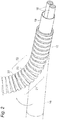
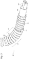
- Fig. 2 is an appearance perspective view which shows a state after the wire harness is bended from a straight state.
- Fig. 3 is an appearance perspective view which shows that a route keeping tape is wound around a bent part of the wire harness.
- Fig. 4A is a longitudinal sectional view of the wire harness before a corrugated tube is bended
- Fig. 4B is a longitudinal sectional view of the wire harness after the corrugated tube is bended.
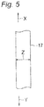
- Fig. 5 is an illustrative view to describe the extensibility of the route keeping tape.
- Fig. 1 is a schematic view which shows an example when the wire harness according to one embodiment of the present invention is wired in a hybrid vehicle.
- Fig. 2 is an appearance perspective view which shows a state after the wire harness is bended from a straight state.
- Fig. 3 is an appearance
- FIG. 6A is a figure which shows an example of the cross-section of the convex parts and the concave parts of the corrugated tube
- Fig. 6B is a figure which shows another example
- Fig. 6C is a figure which shows an example of the cross-section of the convex parts and the concave parts of a traditional corrugated tube.
- a hybrid vehicle 1 is a vehicle which is driven by mixing two powers of an engine 2 and a motor unit 3.
- the electric power from a battery 5 (battery pack) is supplied to the motor unit 3 via an inverter unit 4.
- the engine 2, the motor unit 3 and the inverter unit 4 are carried in an engine room 6 at the position of the front wheels and the like.
- the battery 5 is carried in a vehicle rear part 7 of rear wheels and the like (the battery 5 may be carried in an indoor space behind the engine room 6).
- the motor unit 3 and the inverter unit 4 are connected by a well-known high voltage wire harness 8.
- the battery 5 and the inverter unit 4 are connected by a high voltage wire harness 9 according to the present embodiment.
- the wire harness 9 and the battery 5 are connected through a junction block 12 which the battery 5 is provided with.
- a rear end 13 of the wire harness 9 is connected to the junction block 12 with a connector.
- the side of the wire harness 9 at the rear end 13 is wired above the floor at the indoor side of the vehicle.
- the side of the wire harness 9 at a front end 14 is also wired above the floor.
- the side of the wire harness 9 at a front end 14 is connected to the inverter unit 4 with a connector.
- a middle part 10, which is located between the front end 14 and the rear end 13, of the wire harness 9 is wired below a vehicle body floor 11.
- the motor unit 3 includes a motor (not shown in the figure) and a generator (not shown in the figure) in construction.
- the inverter unit 4 includes an inverter (not shown in the figure) and a converter (not shown in the figure) in construction.
- the motor unit 3 is formed as a motor assembly including a shielding case (not shown in the figure).
- the inverter unit 4 is also formed as an inverter assembly including a shielding case.
- the battery 5 is a Ni-MH battery or Li-ion battery, and is modularized. An electricity accumulating device such as a capacitor may be used.
- the battery 5 is not particularly limited to the construction according to the present embodiment as long as the battery 5 may be used for the hybrid vehicle 1 or an electric vehicle.
- a structure of the wire harness 9 is described below in detail with reference to Figs. 2 to 5 .
- the wire harness 9 includes two electric wires 18, an electromagnetic shielding member 19 which collectively covers the two electric wires 18, and a corrugated tube 16 which is provided at the outer side of the electromagnetic shielding member 19 to cover the electromagnetic shielding member 19 and functions as an exterior member.
- the electric wire 18 is a conductive path which includes a conductor and an insulator, and is formed to have a length that is necessary for electrical connection. Connectors are provided respectively at the two ends of the electric wire 18, one end is connected to the connector of the junction block 12 (refer to Fig. 1 ) and the other end is connected to the connector of the inverter unit 4 (refer to Fig. 1 ), respectively.
- the conductor is manufactured of copper, copper alloy, aluminum or aluminum alloy.
- the conductor may be either a conductor structure in which strands are twisted or a rod-like conductor structure whose cross section is a rectangular shape or a round shape (for example, a conductor structure with a rectangular single core or a round single core, and in this case, the electric wire itself becomes rod-like).
- two electric wires 18 are used as the conductive paths, but the number of the electric wires 18 is not limited, and the conductive path is also not limited to electric wires.
- the electromagnetic shielding member 19 is intended to prevent electrical signals transmitted through the electric wires 18 from being affected by the electromagnetic wave from the outside, and the electromagnetic shielding member 19 is formed of a shielding member containing a conductive metal foil or a metal foil alone into a pipe-like shape.
- the electromagnetic shielding member 19 is formed to have about the same length as the full length of the two electric wires 18.
- the electromagnetic shielding member 19 contains a metal foil in this embodiment, but the present invention is not limited to this. That is, as long as the electromagnetic wave can be dealt with, for example, a web which has a number of extra-fine strands may be used as the electromagnetic shielding member 19. In this case, the web has conductivity and is formed into a pipe-like shape.
- the corrugated tube 16 is a bendable tubular exterior member (tube body) which has flexibility, and is a resin/metal tube (bellow tube) which has convex parts and concave parts (ridges and valleys) which are formed continuously on the outer peripheral surface along the longitudinal direction of the electric wire 18. That is, as shown in Fig. 4A , the corrugated tube 16 is formed with the convex parts and the concave parts, which extend in the peripheral direction, alternately along the longitudinal direction. The top surfaces of the convex parts are formed on a peripheral surface which extends in parallel to the central axis of the corrugated tube 16 in a cross section in parallel to the central axis.
- the corrugated tube 16 of the present embodiment is a resin article which has a circular cross section, but the present invention is not limited to the circular cross section, an oval cross section, quadrangular cross section or the like is also possible.
- bent part 20A to change the direction of the wire harness 9 in the vehicle indoor room to the inverter unit 4
- bent part 20B to change the direction of the wire harness 9 from below the vehicle body floor 11 to the vehicle indoor room
- bent part 20C to change the direction of the wire harness 9 from the vehicle indoor room to below the vehicle body floor 11.
- the bent part 20 is a bent part of the wire harness 9, and is also a bent part of the corrugated tube 16 at the same time.
- a number 21 at the bent part 20 shows an outer side part which has a larger R (curvature).
- a number 22 shows an inner side part which has a smaller R.
- a number 23 shows a side part which is a part that connects the outer side part 21 and the inner side part 22.
- a route keeping tape 17 is wound helically around the bent part 20 in a longitudinal direction of the corrugated tube 16 to maintain the bended shape of the bent part 20.
- the route keeping tape 17 is used to maintain the bended shape of the corrugated tube 16 by being wound around the corrugated tube 16. Therefore, the route keeping tape 17 is processed (for example, oriented) so that the route keeping tape 17 cannot extend or buckle (fold) to a degree of almost having no deformation in the widthwise direction (a Z direction in Fig. 5 ). The route keeping tape 17 is so formed that the route keeping tape 17 is more difficult to extend or buckle in the widthwise direction than the corrugated tube 16. Since the details of the above-described process is well known, the description is omitted herein.
- a metal foil tape, a hard resin tape or the like can be used as the route keeping tape 17.
- an aluminum foil tape, a stainless steel tape or the like is preferred to be used as the metal foil tape, but the material is not limited to these.
- Plating may be performed as needed.
- Adhesive is applied to one side surface of the metal foil tape.
- a polycarbonate sheet (of a tape shape), an acrylic sheet (of a tape shape) or the like can be used as the hard resin tape, but the material is not limited to these.
- Adhesive is applied to one side surface of the hard resin tape.
- an interval between a ridge (convex part) 33 and a ridge 33 adjacent to the ridge 33 at the upper side of the corrugated tube 16 (a pitch A1) is equal to an interval between a ridge (convex part) 31 and a ridge 31 adjacent to the ridge 31 at the lower side of the corrugated tube 16 (a pitch A1).
- an interval between the ridge 33 and the adjacent ridge 33 at the outer side part 21 of the corrugated tube 16 becomes larger than the pitch A1.
- an interval between the ridge 31 and the adjacent ridge 31 at the inner side part 22 of the corrugated tube 16 becomes smaller than the pitch A1. That is, the corrugated tube 16 expands at the outer side part 21 in the longitudinal direction and contracts at the inner side part 22 in the longitudinal direction.
- a force which makes the corrugated tube 16 return to a state before the corrugated tube 16 is bended (a restoring force) is applied, and the corrugated tube 16 returns to the original state shown in Fig. 4A . That is, the wire harness 9 returns to a straight line shape, and is not maintained in the bended shape.
- the route keeping tape 17 is wound helically around the bent part 20 along the longitudinal direction of the corrugated tube 16 to fix the interval between the ridges 33, 33 arranged to be adjacent to each other (a width A2 in Fig. 4B ) and the interval between the ridges 31, 31 arranged to be adjacent to each other (a width A3 in Fig. 4B ).
- the route keeping tape 17 is so formed that the width of the route keeping tape 17 in the central axis direction of the corrugated tube 16 is longer than the width of the bottom surfaces which define the valleys (concave parts) in the central axis direction.
- the route keeping tape 17 is wound around the corrugated tube 16 in the longitudinal direction to cover the valleys 32, 32 arranged to be adjacent to each other and to cover the valleys 34, 34 arranged to be adjacent to each other (refer to Fig. 3 ).
- the route keeping tape 17 which is more difficult to extend or buckle in the widthwise direction than the corrugated tube 16 is wound around the corrugated tube 16 to fix the interval between the ridges 33, 33 arranged to be adjacent to each other and the interval between the ridges 31, 31 arranged to be adjacent to each other, the width A2 at the outer side part 21 is difficult to return to the width A1. Further, the width A3 at the inner side part 22 is difficult to return to the width A1. Therefore, the interval between the ridges 33, 33 arranged to be adjacent to each other at the outer side part 21 and the interval between the ridges 31, 31 arranged to be adjacent to each other at the inner side part 22 can be maintained constant, respectively. Therefore, the maintenance of the bended state of the bent part 20 of the corrugated tube 16 (route maintenance) can be performed surely.
- the shapes of the ridges and valleys of the corrugated tube are preferable, for example, as those shown in Figs. 6A and 6B .
- letters S show ridges (convex parts) and letters T show valleys (concave parts).
- the shape of a traditional corrugated tube 66 in which ridges 71 and valleys 72 alternate continuously is a shape which has curved top parts, as shown in Fig. 6C . Therefore, when the route keeping tape 17 is wound around the corrugated tube 66 by the above-described method, the areas where the route keeping tape 17 is attached to two ridges 71 adjacent to a valley 72 are limited to the areas close to the tops of the ridges 71.
- this pitch a is the same over the full length of the wire harness.
- the width of the ridge 61 can be increased. That is, the wire harness 9 according to the present embodiment is so formed that for the corrugated tube 56, the width of the top surface of the ridge (the convex part) 61 in the central axis direction is longer than the width of the bottom surface which defines the valley (the concave part) 62 in the central axis direction. Therefore, the areas where the route keeping tape 17 is attached to the ridges 61 become larger than before. Therefore, the route holding force of the wire harness 9 can be improved.
- the route keeping tape 17 can maintain the bended shape of the bent part 20 by being wound around the bent part 20 along the longitudinal direction as described above.
- the wire harness 9 of the present embodiment not only a flexible corrugated tube is simply provided as an exterior member of the conductive path, but the corrugated tube may be maintained in a desired shape.
- a low cost, versatile wire harness for which a protector is not necessary can be provided. That is, for the wire harness 9 according to the present embodiment, since standard components (replaceable components) such as, the corrugated tube and the route keeping tape are used as substitutes for the resin molded protector, there is no need for vehicle exclusive components or metal molds. Therefore, the manufacturing cost of the wire harness can be reduced. Since the route keeping tape is used instead of a protector, the weight can be reduced and design modification can be easy to perform.
- the route keeping tape 17 in the embodiment described above is difficult to extend or buckle in the widthwise direction, but the route keeping tape 17 may slightly extend in the longitudinal direction.
- the wire harness according to the present invention is useful in that a route keeping tape is used for an exterior member instead of a protector and a desired shape of the exterior member is maintained.
Landscapes
- Engineering & Computer Science (AREA)
- Architecture (AREA)
- Civil Engineering (AREA)
- Structural Engineering (AREA)
- Mechanical Engineering (AREA)
- Details Of Indoor Wiring (AREA)
- Insulated Conductors (AREA)
- Installation Of Indoor Wiring (AREA)
Claims (4)
- Un faisceau de fils (9) comprenant:un élément extérieur (16), ayant une flexibilité et une forme tubulaire etrecouvrant au moins une voie conductrice; etune bande de maintien de la voie (17), qui est plus difficile à étendre et à boucler dans une direction de largeur que l'élément extérieur (16),dans lequel la bande de maintien de la voie (17) est enroulée en hélice autour d'une partie coudée (20), qui est formée en courbant l'élément extérieur (16), le long d'une direction longitudinale.
- Le faisceau de fils (9) selon la revendication 1, dans lequel l'élément extérieur (16) est formé avec des parties convexes et des parties concaves qui se prolongent dans une direction périphérique, alternativement selon la direction longitudinale et les surfaces supérieures des parties convexes sont formées sur une surface périphérique qui se prolonge parallèlement à un axe central de l'élément extérieur (16) dans une section transversale parallèle à l'axe central, et une largeur des surfaces supérieures des parties convexes dans la direction de l'axe central est plus longue qu'une largeur des surfaces inférieures qui définissent les parties concaves dans la direction de l'axe central.
- Le faisceau de fils (9) selon la revendication 2, dans lequel une largeur de la bande de maintien de la voie (17) dans la direction de l'axe central est plus longue que la largeur des surfaces de fond qui définissent les parties concaves dans la direction de l'axe central, de sorte que la bande de maintien de la route (17) est enroulée autour de la partie coudée (20) pour couvrir les parties concaves.
- Le faisceau de fils (9) selon la revendication 1, dans lequel l'élément extérieur (16) est formé avec des parties convexes et des parties concaves qui se prolongent dans une direction périphérique, alternativement selon une direction longitudinale,
les surfaces supérieures des parties concaves sont formées en une forme plane, un angle de soulèvement des parties convexes est tranchant et une largeur des surfaces supérieures des parties convexes dans une direction d'axe central de l'élément extérieur (16) est longue.
Applications Claiming Priority (2)
| Application Number | Priority Date | Filing Date | Title |
|---|---|---|---|
| JP2011160134A JP5823757B2 (ja) | 2011-07-21 | 2011-07-21 | ワイヤハーネス |
| PCT/JP2012/068499 WO2013012075A1 (fr) | 2011-07-21 | 2012-07-20 | Faisceau électrique |
Publications (3)
| Publication Number | Publication Date |
|---|---|
| EP2736133A1 EP2736133A1 (fr) | 2014-05-28 |
| EP2736133A4 EP2736133A4 (fr) | 2015-12-09 |
| EP2736133B1 true EP2736133B1 (fr) | 2016-12-07 |
Family
ID=47558250
Family Applications (1)
| Application Number | Title | Priority Date | Filing Date |
|---|---|---|---|
| EP12814390.6A Active EP2736133B1 (fr) | 2011-07-21 | 2012-07-20 | Faisceau électrique |
Country Status (5)
| Country | Link |
|---|---|
| US (1) | US9505358B2 (fr) |
| EP (1) | EP2736133B1 (fr) |
| JP (1) | JP5823757B2 (fr) |
| CN (1) | CN103688431A (fr) |
| WO (1) | WO2013012075A1 (fr) |
Families Citing this family (20)
| Publication number | Priority date | Publication date | Assignee | Title |
|---|---|---|---|---|
| BR112015018101A2 (pt) | 2013-02-07 | 2017-07-18 | Abb Technology Ltd | dispositivo de isolamento elétrico tubular, arranjo de cabo de transmissão de energia elétrica de alta tensão e método para prover um cabo de transmissão flexível isolado de energia elétrica de alta tensão |
| JP6134252B2 (ja) * | 2013-11-06 | 2017-05-24 | タイガースポリマー株式会社 | 管継手およびその製造方法 |
| EP2993749A1 (fr) * | 2014-09-05 | 2016-03-09 | Nexans | Agencement de liaison électrique d'appareils électriques |
| JP2017011799A (ja) * | 2015-06-17 | 2017-01-12 | 住友電装株式会社 | 輻射熱遮蔽コルゲートチューブ形成用シートおよびワイヤハーネス |
| WO2017040470A1 (fr) * | 2015-09-02 | 2017-03-09 | Commscope Technologies Llc | Câble coaxial à conducteur extérieur à moindre contrainte |
| WO2017068630A1 (fr) * | 2015-10-19 | 2017-04-27 | 日立金属株式会社 | Faisceau de câbles et élément d'atténuation d'ondes électromagnétiques |
| JP6276743B2 (ja) | 2015-12-14 | 2018-02-07 | 矢崎総業株式会社 | 外装部材及びワイヤハーネス |
| JP6702140B2 (ja) | 2016-03-29 | 2020-05-27 | トヨタ車体株式会社 | 樹脂部品、及びその樹脂部品の製造方法 |
| WO2017169190A1 (fr) * | 2016-03-29 | 2017-10-05 | トヨタ車体株式会社 | Constituant de résine et procédé de production d'un constituant de résine |
| WO2017222074A1 (fr) | 2016-06-24 | 2017-12-28 | 矢崎総業株式会社 | Structure de circuit de véhicule |
| JP6752278B2 (ja) * | 2016-06-24 | 2020-09-09 | 矢崎総業株式会社 | 車両用回路体 |
| WO2017222073A1 (fr) | 2016-06-24 | 2017-12-28 | 矢崎総業株式会社 | Structure de circuit de véhicule |
| CN116142103A (zh) | 2016-06-24 | 2023-05-23 | 矢崎总业株式会社 | 车辆电路体 |
| CN109415026B (zh) * | 2016-06-24 | 2022-02-25 | 矢崎总业株式会社 | 车辆电路体 |
| JP7087254B2 (ja) * | 2016-10-24 | 2022-06-21 | 富士通株式会社 | 電子機器 |
| JP7056544B2 (ja) * | 2018-12-26 | 2022-04-19 | 株式会社オートネットワーク技術研究所 | ワイヤハーネス配索部材 |
| JP2020149781A (ja) * | 2019-03-11 | 2020-09-17 | 株式会社オートネットワーク技術研究所 | ワイヤハーネス |
| JP7238817B2 (ja) * | 2020-02-03 | 2023-03-14 | トヨタ自動車株式会社 | 配策材およびその製造方法 |
| JP7098668B2 (ja) * | 2020-02-19 | 2022-07-11 | 矢崎総業株式会社 | スパイラルチューブの製造方法 |
| JP2022108843A (ja) * | 2021-01-14 | 2022-07-27 | 住友電装株式会社 | ワイヤハーネス |
Family Cites Families (12)
| Publication number | Priority date | Publication date | Assignee | Title |
|---|---|---|---|---|
| WO1995028299A1 (fr) * | 1994-04-15 | 1995-10-26 | United Technologies Automotive, Inc. | Support pour dispositif de retenue d'un ensemble harnais de câbles et detecteur associe |
| US5971033A (en) * | 1996-04-12 | 1999-10-26 | Lanz; Werner | Profiled tube, corrugated hose or the like elongate portion with mutually parallel peripheral grooves |
| JP3468013B2 (ja) | 1997-03-06 | 2003-11-17 | 住友電装株式会社 | コルゲートチューブで外装したワイヤハーネスの構造 |
| JP2004224156A (ja) | 2003-01-22 | 2004-08-12 | Honda Motor Co Ltd | 車両用電力ケーブル保持構造 |
| US6960722B2 (en) | 2003-03-04 | 2005-11-01 | Federal-Mogul World Wide, Inc. | Multi-branch junction overwrap |
| US7435899B2 (en) * | 2004-03-03 | 2008-10-14 | Yazaki Corporation | Corrugated tube, apparatus for perforating corrugated tube and method of perforating corrugated tube |
| US7484535B2 (en) | 2005-03-14 | 2009-02-03 | Advanced Drainage Systems, Inc. | Corrugated pipe with outer layer |
| JP2007024228A (ja) | 2005-07-19 | 2007-02-01 | Kanaflex Corporation | コルゲート複合管 |
| US7156128B1 (en) | 2005-06-21 | 2007-01-02 | Kanaflex Corporation | Synthetic resin pipe |
| EP1972256B1 (fr) * | 2006-01-13 | 2016-04-13 | Olympus Corporation | Endoscope et endoscope rotatif auto-moteur |
| US8653372B2 (en) * | 2008-08-07 | 2014-02-18 | Sumitomo Wiring Systems, Ltd. | Wire harness |
| JP2010049947A (ja) | 2008-08-22 | 2010-03-04 | Yazaki Corp | ワイヤハーネス |
-
2011
- 2011-07-21 JP JP2011160134A patent/JP5823757B2/ja active Active
-
2012
- 2012-07-20 US US14/233,451 patent/US9505358B2/en active Active
- 2012-07-20 CN CN201280036162.XA patent/CN103688431A/zh active Pending
- 2012-07-20 EP EP12814390.6A patent/EP2736133B1/fr active Active
- 2012-07-20 WO PCT/JP2012/068499 patent/WO2013012075A1/fr active Application Filing
Non-Patent Citations (1)
| Title |
|---|
| None * |
Also Published As
| Publication number | Publication date |
|---|---|
| CN103688431A (zh) | 2014-03-26 |
| JP5823757B2 (ja) | 2015-11-25 |
| JP2013027168A (ja) | 2013-02-04 |
| EP2736133A1 (fr) | 2014-05-28 |
| WO2013012075A1 (fr) | 2013-01-24 |
| US9505358B2 (en) | 2016-11-29 |
| EP2736133A4 (fr) | 2015-12-09 |
| US20140174784A1 (en) | 2014-06-26 |
Similar Documents
| Publication | Publication Date | Title |
|---|---|---|
| EP2736133B1 (fr) | Faisceau électrique | |
| JP5311921B2 (ja) | ワイヤハーネス | |
| JP5823758B2 (ja) | ワイヤハーネス | |
| JP5231104B2 (ja) | ワイヤハーネス | |
| JP5269519B2 (ja) | ワイヤハーネス製造方法 | |
| EP2317619B1 (fr) | Element de protection et faisceau de cables | |
| CN105655824B (zh) | 线束 | |
| EP2648941B1 (fr) | Faisceau électrique et son procédé de réalisation | |
| EP2666169B1 (fr) | Chemin conducteur à haute tension et faisceau de câbles | |
| WO2016031814A1 (fr) | Élément de couverture externe pour faisceau de câbles et faisceau de câbles | |
| WO2015178306A1 (fr) | Faisceau de fils | |
| JP6434221B2 (ja) | ワイヤハーネス | |
| JP5835893B2 (ja) | ワイヤハーネス | |
| JP5938785B2 (ja) | ワイヤハーネス | |
| JP2013026015A (ja) | ワイヤハーネス | |
| JP5948658B2 (ja) | ワイヤハーネス | |
| JP5629799B2 (ja) | 車体床下ワイヤハーネスの保護部材 | |
| JP5629800B2 (ja) | ワイヤハーネス | |
| JP6145437B2 (ja) | ワイヤハーネス用の外装部材、及びワイヤハーネス |
Legal Events
| Date | Code | Title | Description |
|---|---|---|---|
| PUAI | Public reference made under article 153(3) epc to a published international application that has entered the european phase |
Free format text: ORIGINAL CODE: 0009012 |
|
| 17P | Request for examination filed |
Effective date: 20140121 |
|
| AK | Designated contracting states |
Kind code of ref document: A1 Designated state(s): AL AT BE BG CH CY CZ DE DK EE ES FI FR GB GR HR HU IE IS IT LI LT LU LV MC MK MT NL NO PL PT RO RS SE SI SK SM TR |
|
| DAX | Request for extension of the european patent (deleted) | ||
| RA4 | Supplementary search report drawn up and despatched (corrected) |
Effective date: 20151111 |
|
| RIC1 | Information provided on ipc code assigned before grant |
Ipc: H01B 7/00 20060101ALI20151105BHEP Ipc: H02G 3/04 20060101AFI20151105BHEP Ipc: H01B 7/17 20060101ALI20151105BHEP Ipc: B60R 16/02 20060101ALI20151105BHEP |
|
| GRAP | Despatch of communication of intention to grant a patent |
Free format text: ORIGINAL CODE: EPIDOSNIGR1 |
|
| INTG | Intention to grant announced |
Effective date: 20160812 |
|
| GRAS | Grant fee paid |
Free format text: ORIGINAL CODE: EPIDOSNIGR3 |
|
| GRAA | (expected) grant |
Free format text: ORIGINAL CODE: 0009210 |
|
| AK | Designated contracting states |
Kind code of ref document: B1 Designated state(s): AL AT BE BG CH CY CZ DE DK EE ES FI FR GB GR HR HU IE IS IT LI LT LU LV MC MK MT NL NO PL PT RO RS SE SI SK SM TR |
|
| REG | Reference to a national code |
Ref country code: GB Ref legal event code: FG4D |
|
| REG | Reference to a national code |
Ref country code: CH Ref legal event code: EP Ref country code: AT Ref legal event code: REF Ref document number: 852465 Country of ref document: AT Kind code of ref document: T Effective date: 20161215 |
|
| REG | Reference to a national code |
Ref country code: IE Ref legal event code: FG4D |
|
| REG | Reference to a national code |
Ref country code: DE Ref legal event code: R096 Ref document number: 602012026393 Country of ref document: DE |
|
| PG25 | Lapsed in a contracting state [announced via postgrant information from national office to epo] |
Ref country code: LV Free format text: LAPSE BECAUSE OF FAILURE TO SUBMIT A TRANSLATION OF THE DESCRIPTION OR TO PAY THE FEE WITHIN THE PRESCRIBED TIME-LIMIT Effective date: 20161207 |
|
| REG | Reference to a national code |
Ref country code: LT Ref legal event code: MG4D |
|
| REG | Reference to a national code |
Ref country code: NL Ref legal event code: MP Effective date: 20161207 |
|
| PG25 | Lapsed in a contracting state [announced via postgrant information from national office to epo] |
Ref country code: GR Free format text: LAPSE BECAUSE OF FAILURE TO SUBMIT A TRANSLATION OF THE DESCRIPTION OR TO PAY THE FEE WITHIN THE PRESCRIBED TIME-LIMIT Effective date: 20170308 Ref country code: NO Free format text: LAPSE BECAUSE OF FAILURE TO SUBMIT A TRANSLATION OF THE DESCRIPTION OR TO PAY THE FEE WITHIN THE PRESCRIBED TIME-LIMIT Effective date: 20170307 Ref country code: SE Free format text: LAPSE BECAUSE OF FAILURE TO SUBMIT A TRANSLATION OF THE DESCRIPTION OR TO PAY THE FEE WITHIN THE PRESCRIBED TIME-LIMIT Effective date: 20161207 Ref country code: LT Free format text: LAPSE BECAUSE OF FAILURE TO SUBMIT A TRANSLATION OF THE DESCRIPTION OR TO PAY THE FEE WITHIN THE PRESCRIBED TIME-LIMIT Effective date: 20161207 |
|
| REG | Reference to a national code |
Ref country code: AT Ref legal event code: MK05 Ref document number: 852465 Country of ref document: AT Kind code of ref document: T Effective date: 20161207 |
|
| PG25 | Lapsed in a contracting state [announced via postgrant information from national office to epo] |
Ref country code: FI Free format text: LAPSE BECAUSE OF FAILURE TO SUBMIT A TRANSLATION OF THE DESCRIPTION OR TO PAY THE FEE WITHIN THE PRESCRIBED TIME-LIMIT Effective date: 20161207 Ref country code: HR Free format text: LAPSE BECAUSE OF FAILURE TO SUBMIT A TRANSLATION OF THE DESCRIPTION OR TO PAY THE FEE WITHIN THE PRESCRIBED TIME-LIMIT Effective date: 20161207 Ref country code: ES Free format text: LAPSE BECAUSE OF FAILURE TO SUBMIT A TRANSLATION OF THE DESCRIPTION OR TO PAY THE FEE WITHIN THE PRESCRIBED TIME-LIMIT Effective date: 20161207 Ref country code: RS Free format text: LAPSE BECAUSE OF FAILURE TO SUBMIT A TRANSLATION OF THE DESCRIPTION OR TO PAY THE FEE WITHIN THE PRESCRIBED TIME-LIMIT Effective date: 20161207 |
|
| PG25 | Lapsed in a contracting state [announced via postgrant information from national office to epo] |
Ref country code: NL Free format text: LAPSE BECAUSE OF FAILURE TO SUBMIT A TRANSLATION OF THE DESCRIPTION OR TO PAY THE FEE WITHIN THE PRESCRIBED TIME-LIMIT Effective date: 20161207 |
|
| PG25 | Lapsed in a contracting state [announced via postgrant information from national office to epo] |
Ref country code: IS Free format text: LAPSE BECAUSE OF FAILURE TO SUBMIT A TRANSLATION OF THE DESCRIPTION OR TO PAY THE FEE WITHIN THE PRESCRIBED TIME-LIMIT Effective date: 20170407 Ref country code: SK Free format text: LAPSE BECAUSE OF FAILURE TO SUBMIT A TRANSLATION OF THE DESCRIPTION OR TO PAY THE FEE WITHIN THE PRESCRIBED TIME-LIMIT Effective date: 20161207 Ref country code: EE Free format text: LAPSE BECAUSE OF FAILURE TO SUBMIT A TRANSLATION OF THE DESCRIPTION OR TO PAY THE FEE WITHIN THE PRESCRIBED TIME-LIMIT Effective date: 20161207 Ref country code: RO Free format text: LAPSE BECAUSE OF FAILURE TO SUBMIT A TRANSLATION OF THE DESCRIPTION OR TO PAY THE FEE WITHIN THE PRESCRIBED TIME-LIMIT Effective date: 20161207 Ref country code: CZ Free format text: LAPSE BECAUSE OF FAILURE TO SUBMIT A TRANSLATION OF THE DESCRIPTION OR TO PAY THE FEE WITHIN THE PRESCRIBED TIME-LIMIT Effective date: 20161207 |
|
| PG25 | Lapsed in a contracting state [announced via postgrant information from national office to epo] |
Ref country code: SM Free format text: LAPSE BECAUSE OF FAILURE TO SUBMIT A TRANSLATION OF THE DESCRIPTION OR TO PAY THE FEE WITHIN THE PRESCRIBED TIME-LIMIT Effective date: 20161207 Ref country code: IT Free format text: LAPSE BECAUSE OF FAILURE TO SUBMIT A TRANSLATION OF THE DESCRIPTION OR TO PAY THE FEE WITHIN THE PRESCRIBED TIME-LIMIT Effective date: 20161207 Ref country code: BE Free format text: LAPSE BECAUSE OF FAILURE TO SUBMIT A TRANSLATION OF THE DESCRIPTION OR TO PAY THE FEE WITHIN THE PRESCRIBED TIME-LIMIT Effective date: 20161207 Ref country code: BG Free format text: LAPSE BECAUSE OF FAILURE TO SUBMIT A TRANSLATION OF THE DESCRIPTION OR TO PAY THE FEE WITHIN THE PRESCRIBED TIME-LIMIT Effective date: 20170307 Ref country code: PL Free format text: LAPSE BECAUSE OF FAILURE TO SUBMIT A TRANSLATION OF THE DESCRIPTION OR TO PAY THE FEE WITHIN THE PRESCRIBED TIME-LIMIT Effective date: 20161207 Ref country code: PT Free format text: LAPSE BECAUSE OF FAILURE TO SUBMIT A TRANSLATION OF THE DESCRIPTION OR TO PAY THE FEE WITHIN THE PRESCRIBED TIME-LIMIT Effective date: 20170407 Ref country code: AT Free format text: LAPSE BECAUSE OF FAILURE TO SUBMIT A TRANSLATION OF THE DESCRIPTION OR TO PAY THE FEE WITHIN THE PRESCRIBED TIME-LIMIT Effective date: 20161207 |
|
| REG | Reference to a national code |
Ref country code: DE Ref legal event code: R097 Ref document number: 602012026393 Country of ref document: DE |
|
| PLBE | No opposition filed within time limit |
Free format text: ORIGINAL CODE: 0009261 |
|
| STAA | Information on the status of an ep patent application or granted ep patent |
Free format text: STATUS: NO OPPOSITION FILED WITHIN TIME LIMIT |
|
| 26N | No opposition filed |
Effective date: 20170908 |
|
| PG25 | Lapsed in a contracting state [announced via postgrant information from national office to epo] |
Ref country code: DK Free format text: LAPSE BECAUSE OF FAILURE TO SUBMIT A TRANSLATION OF THE DESCRIPTION OR TO PAY THE FEE WITHIN THE PRESCRIBED TIME-LIMIT Effective date: 20161207 Ref country code: SI Free format text: LAPSE BECAUSE OF FAILURE TO SUBMIT A TRANSLATION OF THE DESCRIPTION OR TO PAY THE FEE WITHIN THE PRESCRIBED TIME-LIMIT Effective date: 20161207 |
|
| REG | Reference to a national code |
Ref country code: CH Ref legal event code: PL |
|
| GBPC | Gb: european patent ceased through non-payment of renewal fee |
Effective date: 20170720 |
|
| REG | Reference to a national code |
Ref country code: IE Ref legal event code: MM4A |
|
| REG | Reference to a national code |
Ref country code: FR Ref legal event code: ST Effective date: 20180330 |
|
| PG25 | Lapsed in a contracting state [announced via postgrant information from national office to epo] |
Ref country code: LI Free format text: LAPSE BECAUSE OF NON-PAYMENT OF DUE FEES Effective date: 20170731 Ref country code: IE Free format text: LAPSE BECAUSE OF NON-PAYMENT OF DUE FEES Effective date: 20170720 Ref country code: GB Free format text: LAPSE BECAUSE OF NON-PAYMENT OF DUE FEES Effective date: 20170720 Ref country code: CH Free format text: LAPSE BECAUSE OF NON-PAYMENT OF DUE FEES Effective date: 20170731 |
|
| PG25 | Lapsed in a contracting state [announced via postgrant information from national office to epo] |
Ref country code: FR Free format text: LAPSE BECAUSE OF NON-PAYMENT OF DUE FEES Effective date: 20170731 |
|
| PG25 | Lapsed in a contracting state [announced via postgrant information from national office to epo] |
Ref country code: LU Free format text: LAPSE BECAUSE OF NON-PAYMENT OF DUE FEES Effective date: 20170720 |
|
| PG25 | Lapsed in a contracting state [announced via postgrant information from national office to epo] |
Ref country code: MT Free format text: LAPSE BECAUSE OF NON-PAYMENT OF DUE FEES Effective date: 20170720 |
|
| PG25 | Lapsed in a contracting state [announced via postgrant information from national office to epo] |
Ref country code: MC Free format text: LAPSE BECAUSE OF FAILURE TO SUBMIT A TRANSLATION OF THE DESCRIPTION OR TO PAY THE FEE WITHIN THE PRESCRIBED TIME-LIMIT Effective date: 20161207 Ref country code: HU Free format text: LAPSE BECAUSE OF FAILURE TO SUBMIT A TRANSLATION OF THE DESCRIPTION OR TO PAY THE FEE WITHIN THE PRESCRIBED TIME-LIMIT; INVALID AB INITIO Effective date: 20120720 |
|
| PG25 | Lapsed in a contracting state [announced via postgrant information from national office to epo] |
Ref country code: CY Free format text: LAPSE BECAUSE OF NON-PAYMENT OF DUE FEES Effective date: 20161207 |
|
| PG25 | Lapsed in a contracting state [announced via postgrant information from national office to epo] |
Ref country code: MK Free format text: LAPSE BECAUSE OF FAILURE TO SUBMIT A TRANSLATION OF THE DESCRIPTION OR TO PAY THE FEE WITHIN THE PRESCRIBED TIME-LIMIT Effective date: 20161207 |
|
| PG25 | Lapsed in a contracting state [announced via postgrant information from national office to epo] |
Ref country code: TR Free format text: LAPSE BECAUSE OF FAILURE TO SUBMIT A TRANSLATION OF THE DESCRIPTION OR TO PAY THE FEE WITHIN THE PRESCRIBED TIME-LIMIT Effective date: 20161207 |
|
| PG25 | Lapsed in a contracting state [announced via postgrant information from national office to epo] |
Ref country code: AL Free format text: LAPSE BECAUSE OF FAILURE TO SUBMIT A TRANSLATION OF THE DESCRIPTION OR TO PAY THE FEE WITHIN THE PRESCRIBED TIME-LIMIT Effective date: 20161207 |
|
| PGFP | Annual fee paid to national office [announced via postgrant information from national office to epo] |
Ref country code: DE Payment date: 20230531 Year of fee payment: 12 |