EP2736116A2 - Radarantenne und Radarantennenherstellungsverfahren - Google Patents
Radarantenne und Radarantennenherstellungsverfahren Download PDFInfo
- Publication number
- EP2736116A2 EP2736116A2 EP13193512.4A EP13193512A EP2736116A2 EP 2736116 A2 EP2736116 A2 EP 2736116A2 EP 13193512 A EP13193512 A EP 13193512A EP 2736116 A2 EP2736116 A2 EP 2736116A2
- Authority
- EP
- European Patent Office
- Prior art keywords
- antenna
- unit
- supporting
- radar
- antenna unit
- Prior art date
- Legal status (The legal status is an assumption and is not a legal conclusion. Google has not performed a legal analysis and makes no representation as to the accuracy of the status listed.)
- Granted
Links
Images


Classifications
-
- H—ELECTRICITY
- H01—ELECTRIC ELEMENTS
- H01Q—ANTENNAS, i.e. RADIO AERIALS
- H01Q13/00—Waveguide horns or mouths; Slot antennas; Leaky-waveguide antennas; Equivalent structures causing radiation along the transmission path of a guided wave
- H01Q13/20—Non-resonant leaky-waveguide or transmission-line antennas; Equivalent structures causing radiation along the transmission path of a guided wave
- H01Q13/28—Non-resonant leaky-waveguide or transmission-line antennas; Equivalent structures causing radiation along the transmission path of a guided wave comprising elements constituting electric discontinuities and spaced in direction of wave propagation, e.g. dielectric elements or conductive elements forming artificial dielectric
-
- H—ELECTRICITY
- H01—ELECTRIC ELEMENTS
- H01Q—ANTENNAS, i.e. RADIO AERIALS
- H01Q1/00—Details of, or arrangements associated with, antennas
- H01Q1/12—Supports; Mounting means
- H01Q1/1207—Supports; Mounting means for fastening a rigid aerial element
-
- H—ELECTRICITY
- H01—ELECTRIC ELEMENTS
- H01Q—ANTENNAS, i.e. RADIO AERIALS
- H01Q3/00—Arrangements for changing or varying the orientation or the shape of the directional pattern of the waves radiated from an antenna or antenna system
- H01Q3/02—Arrangements for changing or varying the orientation or the shape of the directional pattern of the waves radiated from an antenna or antenna system using mechanical movement of antenna or antenna system as a whole
- H01Q3/04—Arrangements for changing or varying the orientation or the shape of the directional pattern of the waves radiated from an antenna or antenna system using mechanical movement of antenna or antenna system as a whole for varying one co-ordinate of the orientation
-
- Y—GENERAL TAGGING OF NEW TECHNOLOGICAL DEVELOPMENTS; GENERAL TAGGING OF CROSS-SECTIONAL TECHNOLOGIES SPANNING OVER SEVERAL SECTIONS OF THE IPC; TECHNICAL SUBJECTS COVERED BY FORMER USPC CROSS-REFERENCE ART COLLECTIONS [XRACs] AND DIGESTS
- Y10—TECHNICAL SUBJECTS COVERED BY FORMER USPC
- Y10T—TECHNICAL SUBJECTS COVERED BY FORMER US CLASSIFICATION
- Y10T29/00—Metal working
- Y10T29/49—Method of mechanical manufacture
- Y10T29/49002—Electrical device making
- Y10T29/49016—Antenna or wave energy "plumbing" making
Definitions
- the present invention relates to a radar antenna including an antenna unit having dielectric bodies.
- radar antennas each including an antenna unit and a housing unit has been known.
- the antenna unit radiates outside radio waves.
- the housing unit is built therein with a motor for rotating the antenna unit, a coaxial cable for supplying radio waves to the antenna unit, etc.
- antenna units have conventionally been known, such as, an antenna unit having a shape in which the cross-section of an opening part thereof gradually spreads toward outside (horn shape, trumpet shape).
- horn shape a shape in which the cross-section of an opening part thereof gradually spreads toward outside
- the antenna unit is generally substantially directly attached to the housing unit (with an attaching plate interposing therebetween).
- JP1991-042723A discloses an antenna unit having dielectric bodies.
- the antenna unit includes a dielectric body waveguide mechanism comprised of two dielectric body flat plates opposing to each other.
- the antenna unit having the dielectric bodies as disclosed in JP1991-042723A when a metal is disposed near the antenna unit, a beam cannot be formed appropriately. Therefore, the antenna unit having the dielectric bodies is preferred not to be disposed near the housing body, different from the conventional horn-shaped antenna unit.
- JP1991-042723A only discloses the configuration having the shape of the antenna unit with the dielectric bodies, and the details in supporting the antenna unit are not disclosed. For this reason, an appropriate configuration for supporting an antenna unit having dielectric bodies has been desired.
- JP1991-042723A the dielectric body flat plates are disclosed to be made of FRP.
- the configuration of using FRP to the dielectric body waveguide mechanism of the antenna unit is disclosed and the use of FRP to other members is not disclosed.
- the present invention is made in view of the above situations, and mainly aims to provide a radar antenna including an antenna unit having dielectric bodies and for supporting the antenna unit such that a beam formation is not negatively influenced.
- the radar antenna includes an antenna unit, a housing unit, and an antenna supporting unit.
- the antenna unit is provided with dielectric bodies in a front part thereof in a radio wave radiating direction.
- the housing unit supplies a radio wave to the antenna unit.
- the antenna supporting unit is attached between the antenna unit and the housing unit to separate the antenna unit from the housing unit.
- the antenna unit can be separated from the housing unit, a beam can be formed appropriately.
- the antenna supporting unit may include a pedestal attached to the housing unit, an attaching base attached to the antenna unit, and a plurality of supporting bars connecting the pedestal with the attaching base.
- the antenna unit can be separated from the housing unit with the simple configuration. Although influence of wind is easily received due to the separation of the antenna unit from the housing unit, wind can pass through between the plurality of supporting bars with the configuration described above. Therefore, the radar antenna can be supported stably.
- the antenna supporting unit can be made of FRP (fiber-reinforced plastic).
- the antenna supporting unit with FRP excelling in an electrical property, the influence on the beam formation can be reduced more. Further, by using FRP, the antenna supporting unit having a light weight, thermal resistance, and corrosion resistance can be realized.
- the antenna supporting unit may be built by connecting members made of FRP with each other in an overlapped manner.
- the strength of the antenna supporting unit can be improved compared to the configuration of creating the components individually and fixing therebetween with fastening tools (e.g., screws).
- At least a part of one of the supporting bars, at least a part of another one of the supporting bars adjacent thereto, and a part of the pedestal between the two supporting bars may be formed by a single FRP sheet.
- the parts where a stress easily concentrates can be built integrally instead of separately. Therefore, the strength of the antenna supporting unit can be improved.
- At least a part of an outermost supporting bar and an end part of the pedestal may be formed by a single FRP sheet.
- the parts where a stress easily concentrates can be built integrally instead of separately. Therefore, the strength of the antenna supporting unit can be improved.
- the plurality of supporting bars may include two supporting bars.
- a gap between the supporting bars on the pedestal side may be less than that on the attaching base side.
- the antenna unit can be supported stably even if the number of supporting bars is two.
- the contour of the supporting bar may be a solid cylindrical shape.
- the radar antenna can pass wind rearward. Therefore, the antenna unit can be supported more stably.
- the antenna supporting unit may incline toward a rear part of the antenna unit in the radio wave radiating direction.
- the antenna supporting unit supports the antenna unit having the dielectric bodies, it supports the rear part of the antenna unit in the radio wave radiating direction so as to suppress the influence of the radio wave characteristic. Therefore, by inclining the antenna supporting unit as described above, the center of gravity of the antenna unit can be drawn close to the axis of rotation of the antenna unit. Thus, the antenna unit can be supported stably.
- At least one of the supporting bars may incline in a longitudinal direction of the antenna unit.
- the antenna unit can be supported more stably compared to the configuration of supporting the center part of the antenna unit.
- the supporting bars may be hollow therein.
- the hollow member is more convenient to form compared to the solid member, the manufacturing cost of the antenna supporting units can be reduced. Moreover, the antenna supporting unit can be reduced in weight.
- Another aspect of the present invention provides a method of manufacturing radar antennas.
- the method includes connecting components formed by FRP with each other in an overlapped manner, and building an antenna supporting unit for separating an antenna unit from a housing unit.
- the method also includes attaching the antenna supporting unit to the housing unit for supplying a radio wave to be radiated from the antenna unit.
- the method also includes attaching the antenna unit to the antenna supporting unit, the antenna unit being provided with dielectric bodies in a front part thereof in a radio wave radiating direction.
- the antenna unit can be separated from the housing unit. Therefore, radar antennas that can appropriately form beams can be manufactured.
- Fig. 1 is a schematic front view of a radar antenna according to one embodiment of the present invention
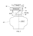
- Fig. 2 is a schematic side view of the radar antenna
- Fig. 3 is a front view of an antenna supporting part
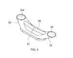
- Fig. 4 is a cross-sectional perspective view of the antenna supporting part.
- Fig. 1 is a schematic front view of a radar antenna according to this embodiment of the present invention.
- Fig. 2 is a schematic side view of the radar antenna.
- a radar antenna 10 radiates pulse-shaped radio waves and receives reflection waves of the radiated radio waves.
- the radar antenna 10 repeats transception of the radio waves while rotating in the horizontal plane.
- Each reflection wave received by the radar antenna 10 is analyzed by a transceiver, an indicator and the like (not illustrated). Thus, a position, a speed and the like of a target object existing around the radar antenna 10 can be obtained.
- the radar antenna 10 includes a housing unit 20, an antenna supporting unit 30, and an antenna unit 40 having dielectric bodies.
- the housing unit 20 is a box-like member accommodating various components.
- the housing unit 20 includes a motor for driving a rotational shaft 21 for rotating the antenna unit 40, and a circuit and a magnetron for generating the radio wave to be radiated from the antenna unit 40.
- the housing unit 20 is connected with the antenna unit 40 via a coaxial cable (or a waveguide, etc.), and the antenna unit 40 can radiate outside the radio wave supplied from the housing unit 20.
- the antenna unit 40 having the dielectric bodies cannot appropriately form a beam if a metal exists on a front side or obliquely front side thereof in a radio wave radiating direction.
- the antenna supporting unit 30 made of FRP (Fiber Reinforced Plastic) is provided.
- a forward direction of the radio wave radiating direction corresponds to a forward direction of the antenna unit 40
- a backward direction of the radio wave radiating direction corresponds to a rearward direction of the antenna unit 40.
- the antenna supporting unit 30 separates the antenna unit 40 from the housing unit 20.
- the influence that the housing unit 20 gives the beam formation can be reduced.
- the separating distance is preferred to correspond to one wavelength or more of the radio wave to be radiated (about 10cm when the transmission frequency is 3 GHz).
- FPR has a characteristic that it does not easily influence radio waves, the beam formation is rarely influenced.
- GFRP Glass Fiber Reinforced Plastic
- FRP FRP
- GFRP GFRP
- FRP excels in its light weight, thermal resistance, and corrosion resistance, as well as having a small influence on radio waves.
- this embodiment is applied to a ship radar apparatus, FRP is suitable considering the possibility of receiving strong wind and seawater.
- the antenna supporting unit 30 includes a pedestal 31, supporting bars 32 and 33, an attaching base 34, and a cover 35. Moreover, the supporting bar 32 is formed with a hollow section 32a and a fixed portion 32b, and the supporting bar 33 is formed with a hollow section 33a and a fixed portion 33b.
- the pedestal 31 is a plate-like member attached to the housing unit 20.
- the pedestal 31 is connected with the two supporting bars 32 and 33.
- the supporting bars 32 and 33 are cylindrical members (members with cylindrical contours) and are formed to connect the pedestal 31 with the attaching base 34. Moreover, the supporting bars 32 and 33 are arranged such that a gap between the supporting bars 32 and 33 is wider on the attaching base 34 side (antenna unit 40 side) than the pedestal 31 side (arranged in a substantially V-shape). In other words, the supporting bars 32 and 33 incline toward different end parts of the attaching base 34 (antenna unit 40) from each other in a longitudinal direction of the attaching base 34 (see Fig. 1 ) (incline in the longitudinal direction of the antenna unit 40).
- the supporting bars 32 and 33 extend to the attaching base 34 (antenna unit 40) while inclining toward a rear part of the antenna unit 40 (backward in the radio wave radiating direction) for the following reasons.
- the antenna supporting unit 30 supports the rear part of the antenna unit 40.
- the center of gravity of the antenna unit 40 will be largely offset from an axis of rotation of the antenna unit 40. In this case, it becomes difficult to stably support the antenna unit 40 that is rotating.
- the center of gravity of the antenna unit 40 can be drawn close to the axis of rotation of the antenna unit 40. Therefore, the antenna 40 that is rotating can be stably supported.
- the hollow sections 32a and 33a are hollow areas of the cylindrical supporting bars 32 and 33.
- a plurality of layers of FRP are required to be formed so as to thicken the respective members of the antenna supporting unit 30. Therefore, the manufacturing cost is cheaper to create a hollow member than to create a solid member.
- the fixed portions 32b and 33b are plate-like portions formed at contacting positions with the attaching base 34.
- a through hole is formed in each of the fixed portions 32b and 33b, and by inserting a fixing tool (e.g., a bolt) into the through hole to be attached thereto, the supporting bars 32 and 33 can be fixed to the attaching base 34.
- a fixing tool e.g., a bolt
- the attaching base 34 is disposed between the supporting bars 32 and 33, and the antenna unit 40.
- the attaching base 34 is a long-and-thin member having an L-shaped cross-section and is attached to the antenna unit 40 by contacting a lower surface (surface on the housing unit 20 side) and a rear surface (surface on the backward side in the radio wave radiating direction) of the antenna unit 40. Note that, by forming the attaching base 34 to have the L-shaped cross-section, the antenna unit 40 can surely be fixed and the strength of the attaching base 34 can be improved.
- the cover 35 covers a section between the supporting bar 32 and the supporting bar 33.
- the antenna unit 40 is an end-feed-type slot array antenna and can radiate the radio wave in the direction indicated by the arrow (forward arrow) in Fig. 2 .
- the antenna unit 40 includes an antenna case 41, a radiating part 42, and a plurality of dielectric body parts 43.
- the antenna case 41 is a case for covering the respective members configuring the antenna unit 40. Note that, to facilitate the view inside the radar antenna 10, the antenna case 41 is only illustrated about its contour in Fig. 2 .
- the radiating part 42 radiates outside the radio wave supplied from, for example, the coaxial cable.
- the radiating part 42 is comprised of a radiation waveguide formed in the longitudinal direction of the antenna unit 40.
- the radiation waveguide is a tubular member made of metal, where slits are formed at a predetermined interval.
- the radiation waveguide radiates, from the slits to outside (in the radio wave radiating direction), the radio wave supplied from, for example, the coaxial cable.
- the dielectric body parts 43 made of foamed dielectric bodies are disposed in the front part of the antenna unit 40 in the radio wave radiating direction. Specifically, two plates of the dielectric bodies are arranged parallel to each other via a predetermined interval therebetween, and two more plates of the dielectric bodies are disposed outward thereof, respectively.
- a directivity angle (a beam width in a perpendicular direction to the dielectric body parts 43) of the radio wave radiated from the radiation part 42 is controlled according to the interval of the dielectric body parts 43. Note that, the directivity angle can also be adjusted by changing a permittivity of the dielectric body parts 43, in addition to the interval of the dielectric body parts 43.
- the radar antenna 10 can radiate outside the radio wave generated by using the magnetron and the like at a predetermined directivity angle.
- the antenna supporting unit 30 made of FRP separates the antenna unit 40 from the housing unit 20 so as to form the beam appropriately.
- a stress concentrates on the end portions of the supporting bars and it is concerned that one or both of the end portions of the supporting bars may break.
- the breakage is prevented by building the supporting bars 32 and 33 and the pedestal 31 in the following method.
- the portions indicated by a single thick line with arrows at its both ends in Fig. 3 is formed by a single sheet of FRP.
- a portion of the supporting bar 32 and a portion of the supporting bar 33 are formed integrally by a single FRP sheet.
- the manufacturing method of FRP generally includes overlapping layers from an outer-most layer by using an outer mold. Therefore, the part indicated by (1) can be built only by forming FRP, using a relevant mold.
- the portions indicated by (2) and (3) of Fig. 3 in other words, a portion of the supporting bar 32 (the portion at least including the surface thereof on the housing unit 20 side) and a surface of the pedestal 31 (the portion at least including a side surface thereof) are formed integrally by a single FRP sheet, and a portion of the supporting bar 33 (the portion at least including the surface thereof on the housing unit 20 side) and a surface of the pedestal 31 (the portion at least including a side surface thereof) are formed integrally by a single FRP sheet.
- the portions indicated by (2) and (3) of Fig. 3 only require to form FRP by using respective relevant molds, similarly to the portions indicated by (1). Note that, in view of the strength and the like of the antenna supporting unit 30, the directions indicated by the arrows in Fig. 3 are preferred to be matched with the direction of glass fiber.
- the antenna supporting unit 30 can be built in which the portions where the stress concentrates are integrally built.
- the breakage at the connecting positions of the supporting bars 32 and 33 and the pedestal 31 can be prevented.
- the radar antenna 10 of this embodiment includes the antenna unit 40, the housing unit 20, and the antenna unit 30.
- the antenna unit 40 is provided with the dielectric body parts 43 in the front part thereof in the radio wave radiating direction.
- the housing unit 20 supplies the radio wave to the antenna unit 40.
- the antenna supporting unit 30 is the member made of FRP that is attached between the antenna unit 40 and the housing unit 20 to separate the antenna unit 40 from the housing unit 20.
- the antenna unit 40 can be separated from the housing unit 20, the beam can be formed appropriately. Moreover, by building the antenna supporting unit 30 with FRP excelling in an electrical property, the influence on the beam formation can be reduced more. Further, by using FRP, the antenna supporting unit 30 having a light weight, thermal resistance, and corrosion resistance can be realized.
- the number of the supporting bars 32 and 33 is not limited to two, but may be one, three or more.
- the antenna supporting unit 30 may be adjusted in its height by using a different member (e.g., box-shaped member) instead of the supporting bars.
- the installing angles of the supporting bars 32 and 33 are arbitrary and do not need to incline backward in the radio wave radiating direction while inclining in the longitudinal direction.
- the shapes of the supporting bars 32 and 33 are not limited to the cylindrical-shapes, but may be solid cylindrical shapes, cross-sectionally rectangular-shapes, etc.
- the portions formed by a single sheet FRP are arbitrary and may suitably be changed according the configuration, the shape and the like of the antenna supporting unit 30.
- the present invention is not limited to the radar antenna for ships but may also be applied to radar antennas provided to other movable bodies (navigation bodies, such as automobiles, airplanes, etc.). Moreover, the present invention may also be applied to radar antennas of radar apparatuses which perform observations at fixed positions.
Landscapes
- Variable-Direction Aerials And Aerial Arrays (AREA)
- Radar Systems Or Details Thereof (AREA)
- Details Of Aerials (AREA)
- Support Of Aerials (AREA)
- Waveguide Aerials (AREA)
Applications Claiming Priority (1)
| Application Number | Priority Date | Filing Date | Title |
|---|---|---|---|
| JP2012258700A JP6014473B2 (ja) | 2012-11-27 | 2012-11-27 | レーダアンテナ及びレーダアンテナの製造方法 |
Publications (3)
| Publication Number | Publication Date |
|---|---|
| EP2736116A2 true EP2736116A2 (de) | 2014-05-28 |
| EP2736116A3 EP2736116A3 (de) | 2015-01-07 |
| EP2736116B1 EP2736116B1 (de) | 2019-07-03 |
Family
ID=49596167
Family Applications (1)
| Application Number | Title | Priority Date | Filing Date |
|---|---|---|---|
| EP13193512.4A Active EP2736116B1 (de) | 2012-11-27 | 2013-11-19 | Radarantenne und Radarantennenherstellungsverfahren |
Country Status (4)
| Country | Link |
|---|---|
| US (1) | US9640872B2 (de) |
| EP (1) | EP2736116B1 (de) |
| JP (1) | JP6014473B2 (de) |
| CN (2) | CN203813013U (de) |
Families Citing this family (4)
| Publication number | Priority date | Publication date | Assignee | Title |
|---|---|---|---|---|
| WO2013123089A1 (en) * | 2012-02-17 | 2013-08-22 | Cohen Nathaniel L | Apparatus for using microwave energy for insect and pest control and methods thereof |
| JP6014473B2 (ja) * | 2012-11-27 | 2016-10-25 | 古野電気株式会社 | レーダアンテナ及びレーダアンテナの製造方法 |
| US10742315B1 (en) * | 2019-05-21 | 2020-08-11 | Waymo Llc | Automotive communication system with dielectric waveguide cable and wireless contactless rotary joint |
| CN114447563B (zh) * | 2021-12-15 | 2025-07-25 | 哈尔滨龙易电气有限公司 | 一种天线设备的制造方法及天线设备 |
Citations (1)
| Publication number | Priority date | Publication date | Assignee | Title |
|---|---|---|---|---|
| JPH0342723A (ja) | 1989-07-11 | 1991-02-22 | Nec Corp | データ処理装置 |
Family Cites Families (14)
| Publication number | Priority date | Publication date | Assignee | Title |
|---|---|---|---|---|
| US3234558A (en) * | 1962-09-26 | 1966-02-08 | Selenia Ind Elettroniche | Radar antenna consisting of a linear source with its directivity in a plane at rightangles to the line, obtained by a dielectric structure |
| GB1084065A (de) * | 1965-03-02 | |||
| JPS60216605A (ja) | 1984-03-10 | 1985-10-30 | Tokyo Keiki Co Ltd | スロツト・アレイ・アンテナ装置 |
| GB2158650B (en) * | 1984-03-14 | 1987-12-23 | Tokyo Keiki Kk | Slotted waveguide antenna assembly |
| JPS63227204A (ja) * | 1987-03-17 | 1988-09-21 | Tokyo Keiki Co Ltd | スロツト・アレイ・アンテナ |
| DE3731931A1 (de) * | 1987-09-23 | 1989-04-06 | Pfleiderer Fa G A | Mast fuer mess- oder beleuchtungszwecke, insbesondere fuer flugbefeuerung |
| GB2291948B (en) * | 1988-02-03 | 1996-06-26 | Vickers Shipbuilding & Eng | Improvements in or relating to structures subject to loading |
| US5389940A (en) * | 1992-09-14 | 1995-02-14 | Cal Corporation | Antenna pointing mechanism |
| JP3225339B2 (ja) * | 1995-06-16 | 2001-11-05 | 泰榮商工株式会社 | アンテナ用ラドーム並びにその製造方法 |
| JP3933111B2 (ja) * | 2003-08-25 | 2007-06-20 | 三菱電機株式会社 | 望遠鏡装置 |
| JP4733582B2 (ja) * | 2006-07-24 | 2011-07-27 | 古野電気株式会社 | アンテナ装置 |
| US8144073B2 (en) * | 2008-06-23 | 2012-03-27 | Raytheon Company | Portal structure providing electromagnetic interference shielding features |
| US8159411B2 (en) * | 2008-06-23 | 2012-04-17 | Raytheon Company | Rotary connector providing electromagnetic interference shielding features |
| JP6014473B2 (ja) * | 2012-11-27 | 2016-10-25 | 古野電気株式会社 | レーダアンテナ及びレーダアンテナの製造方法 |
-
2012
- 2012-11-27 JP JP2012258700A patent/JP6014473B2/ja active Active
-
2013
- 2013-11-19 EP EP13193512.4A patent/EP2736116B1/de active Active
- 2013-11-22 US US14/088,316 patent/US9640872B2/en active Active
- 2013-11-27 CN CN201320772197.1U patent/CN203813013U/zh not_active Expired - Lifetime
- 2013-11-27 CN CN201310617023.2A patent/CN103840248B/zh active Active
Patent Citations (1)
| Publication number | Priority date | Publication date | Assignee | Title |
|---|---|---|---|---|
| JPH0342723A (ja) | 1989-07-11 | 1991-02-22 | Nec Corp | データ処理装置 |
Also Published As
| Publication number | Publication date |
|---|---|
| US20140145908A1 (en) | 2014-05-29 |
| US9640872B2 (en) | 2017-05-02 |
| CN103840248B (zh) | 2018-07-17 |
| EP2736116B1 (de) | 2019-07-03 |
| CN103840248A (zh) | 2014-06-04 |
| EP2736116A3 (de) | 2015-01-07 |
| CN203813013U (zh) | 2014-09-03 |
| JP6014473B2 (ja) | 2016-10-25 |
| JP2014107679A (ja) | 2014-06-09 |
Similar Documents
| Publication | Publication Date | Title |
|---|---|---|
| US8149177B1 (en) | Slotted waveguide antenna stiffened structure | |
| JP7399239B2 (ja) | 車載用アンテナ装置 | |
| US9640872B2 (en) | Radar antenna and radar antenna manufacturing method | |
| US4509053A (en) | Blade antenna with shaped dielectric | |
| JP2848601B2 (ja) | アレイアンテナ装置 | |
| EP3183771B1 (de) | Fahrzeugantenne | |
| US20140159949A1 (en) | Aircraft comprising an onboard weather radar antenna provided with inclined panels | |
| KR101975332B1 (ko) | 단벽 도파관 방사를 위한 폴드형 방사 슬롯들 | |
| EP2260537B1 (de) | Antennenspeisungsanordnung | |
| CN106611898B (zh) | 使用串联馈送模式的水平极化波天线 | |
| US6559807B2 (en) | Compact, lightweight, steerable, high-power microwave antenna | |
| EP2375492B1 (de) | Antennenvorrichtung und Radargerät | |
| JP7610574B2 (ja) | 乗物用アンテナ装置ならびにその使用方法および製造方法 | |
| JP6738778B2 (ja) | レーダ装置 | |
| JP5639015B2 (ja) | アンテナ装置、レーダ装置、及び誘電体部材の配置方法 | |
| US9570802B2 (en) | Radar antenna and radar antenna manufacturing method | |
| JP2009198192A (ja) | エンブレム、補正具及びレーダ波のビーム方向補正方法 | |
| JP4328814B2 (ja) | 同軸給電スロットアレイアンテナおよび車両用レーダ装置 | |
| JP2002198727A (ja) | アンテナ装置 | |
| WO2000069021A1 (en) | Concealed radio antenna system | |
| CN210778964U (zh) | 天线单元及相控阵天线 | |
| EP2104177A1 (de) | Antennenspeisungsanordnung | |
| EP4199261B1 (de) | Antenne mit einem strahlungsformungselement und flugzeug mit einer solchen antenne | |
| EP4685997A1 (de) | Antennenvorrichtung und installationsverfahren für eine antennenvorrichtung | |
| JP2015171070A (ja) | アンテナ装置 |
Legal Events
| Date | Code | Title | Description |
|---|---|---|---|
| PUAI | Public reference made under article 153(3) epc to a published international application that has entered the european phase |
Free format text: ORIGINAL CODE: 0009012 |
|
| 17P | Request for examination filed |
Effective date: 20131119 |
|
| AK | Designated contracting states |
Kind code of ref document: A2 Designated state(s): AL AT BE BG CH CY CZ DE DK EE ES FI FR GB GR HR HU IE IS IT LI LT LU LV MC MK MT NL NO PL PT RO RS SE SI SK SM TR |
|
| AX | Request for extension of the european patent |
Extension state: BA ME |
|
| PUAL | Search report despatched |
Free format text: ORIGINAL CODE: 0009013 |
|
| AK | Designated contracting states |
Kind code of ref document: A3 Designated state(s): AL AT BE BG CH CY CZ DE DK EE ES FI FR GB GR HR HU IE IS IT LI LT LU LV MC MK MT NL NO PL PT RO RS SE SI SK SM TR |
|
| AX | Request for extension of the european patent |
Extension state: BA ME |
|
| RIC1 | Information provided on ipc code assigned before grant |
Ipc: H01Q 3/04 20060101ALI20141128BHEP Ipc: H01Q 1/12 20060101AFI20141128BHEP Ipc: H01Q 13/28 20060101ALI20141128BHEP |
|
| R17P | Request for examination filed (corrected) |
Effective date: 20150629 |
|
| RBV | Designated contracting states (corrected) |
Designated state(s): AL AT BE BG CH CY CZ DE DK EE ES FI FR GB GR HR HU IE IS IT LI LT LU LV MC MK MT NL NO PL PT RO RS SE SI SK SM TR |
|
| STAA | Information on the status of an ep patent application or granted ep patent |
Free format text: STATUS: EXAMINATION IS IN PROGRESS |
|
| 17Q | First examination report despatched |
Effective date: 20170731 |
|
| GRAP | Despatch of communication of intention to grant a patent |
Free format text: ORIGINAL CODE: EPIDOSNIGR1 |
|
| STAA | Information on the status of an ep patent application or granted ep patent |
Free format text: STATUS: GRANT OF PATENT IS INTENDED |
|
| INTG | Intention to grant announced |
Effective date: 20190221 |
|
| RAP1 | Party data changed (applicant data changed or rights of an application transferred) |
Owner name: FURUNO ELECTRIC COMPANY LIMITED |
|
| GRAS | Grant fee paid |
Free format text: ORIGINAL CODE: EPIDOSNIGR3 |
|
| GRAA | (expected) grant |
Free format text: ORIGINAL CODE: 0009210 |
|
| STAA | Information on the status of an ep patent application or granted ep patent |
Free format text: STATUS: THE PATENT HAS BEEN GRANTED |
|
| AK | Designated contracting states |
Kind code of ref document: B1 Designated state(s): AL AT BE BG CH CY CZ DE DK EE ES FI FR GB GR HR HU IE IS IT LI LT LU LV MC MK MT NL NO PL PT RO RS SE SI SK SM TR |
|
| REG | Reference to a national code |
Ref country code: GB Ref legal event code: FG4D |
|
| REG | Reference to a national code |
Ref country code: CH Ref legal event code: EP Ref country code: AT Ref legal event code: REF Ref document number: 1152091 Country of ref document: AT Kind code of ref document: T Effective date: 20190715 |
|
| REG | Reference to a national code |
Ref country code: DE Ref legal event code: R096 Ref document number: 602013057335 Country of ref document: DE |
|
| REG | Reference to a national code |
Ref country code: IE Ref legal event code: FG4D |
|
| REG | Reference to a national code |
Ref country code: NL Ref legal event code: MP Effective date: 20190703 |
|
| REG | Reference to a national code |
Ref country code: LT Ref legal event code: MG4D |
|
| REG | Reference to a national code |
Ref country code: AT Ref legal event code: MK05 Ref document number: 1152091 Country of ref document: AT Kind code of ref document: T Effective date: 20190703 |
|
| PG25 | Lapsed in a contracting state [announced via postgrant information from national office to epo] |
Ref country code: LT Free format text: LAPSE BECAUSE OF FAILURE TO SUBMIT A TRANSLATION OF THE DESCRIPTION OR TO PAY THE FEE WITHIN THE PRESCRIBED TIME-LIMIT Effective date: 20190703 Ref country code: HR Free format text: LAPSE BECAUSE OF FAILURE TO SUBMIT A TRANSLATION OF THE DESCRIPTION OR TO PAY THE FEE WITHIN THE PRESCRIBED TIME-LIMIT Effective date: 20190703 Ref country code: PT Free format text: LAPSE BECAUSE OF FAILURE TO SUBMIT A TRANSLATION OF THE DESCRIPTION OR TO PAY THE FEE WITHIN THE PRESCRIBED TIME-LIMIT Effective date: 20191104 Ref country code: BG Free format text: LAPSE BECAUSE OF FAILURE TO SUBMIT A TRANSLATION OF THE DESCRIPTION OR TO PAY THE FEE WITHIN THE PRESCRIBED TIME-LIMIT Effective date: 20191003 Ref country code: NL Free format text: LAPSE BECAUSE OF FAILURE TO SUBMIT A TRANSLATION OF THE DESCRIPTION OR TO PAY THE FEE WITHIN THE PRESCRIBED TIME-LIMIT Effective date: 20190703 Ref country code: CZ Free format text: LAPSE BECAUSE OF FAILURE TO SUBMIT A TRANSLATION OF THE DESCRIPTION OR TO PAY THE FEE WITHIN THE PRESCRIBED TIME-LIMIT Effective date: 20190703 Ref country code: NO Free format text: LAPSE BECAUSE OF FAILURE TO SUBMIT A TRANSLATION OF THE DESCRIPTION OR TO PAY THE FEE WITHIN THE PRESCRIBED TIME-LIMIT Effective date: 20191003 Ref country code: SE Free format text: LAPSE BECAUSE OF FAILURE TO SUBMIT A TRANSLATION OF THE DESCRIPTION OR TO PAY THE FEE WITHIN THE PRESCRIBED TIME-LIMIT Effective date: 20190703 Ref country code: AT Free format text: LAPSE BECAUSE OF FAILURE TO SUBMIT A TRANSLATION OF THE DESCRIPTION OR TO PAY THE FEE WITHIN THE PRESCRIBED TIME-LIMIT Effective date: 20190703 Ref country code: FI Free format text: LAPSE BECAUSE OF FAILURE TO SUBMIT A TRANSLATION OF THE DESCRIPTION OR TO PAY THE FEE WITHIN THE PRESCRIBED TIME-LIMIT Effective date: 20190703 |
|
| PG25 | Lapsed in a contracting state [announced via postgrant information from national office to epo] |
Ref country code: RS Free format text: LAPSE BECAUSE OF FAILURE TO SUBMIT A TRANSLATION OF THE DESCRIPTION OR TO PAY THE FEE WITHIN THE PRESCRIBED TIME-LIMIT Effective date: 20190703 Ref country code: IS Free format text: LAPSE BECAUSE OF FAILURE TO SUBMIT A TRANSLATION OF THE DESCRIPTION OR TO PAY THE FEE WITHIN THE PRESCRIBED TIME-LIMIT Effective date: 20191103 Ref country code: ES Free format text: LAPSE BECAUSE OF FAILURE TO SUBMIT A TRANSLATION OF THE DESCRIPTION OR TO PAY THE FEE WITHIN THE PRESCRIBED TIME-LIMIT Effective date: 20190703 Ref country code: GR Free format text: LAPSE BECAUSE OF FAILURE TO SUBMIT A TRANSLATION OF THE DESCRIPTION OR TO PAY THE FEE WITHIN THE PRESCRIBED TIME-LIMIT Effective date: 20191004 Ref country code: AL Free format text: LAPSE BECAUSE OF FAILURE TO SUBMIT A TRANSLATION OF THE DESCRIPTION OR TO PAY THE FEE WITHIN THE PRESCRIBED TIME-LIMIT Effective date: 20190703 Ref country code: LV Free format text: LAPSE BECAUSE OF FAILURE TO SUBMIT A TRANSLATION OF THE DESCRIPTION OR TO PAY THE FEE WITHIN THE PRESCRIBED TIME-LIMIT Effective date: 20190703 |
|
| PG25 | Lapsed in a contracting state [announced via postgrant information from national office to epo] |
Ref country code: TR Free format text: LAPSE BECAUSE OF FAILURE TO SUBMIT A TRANSLATION OF THE DESCRIPTION OR TO PAY THE FEE WITHIN THE PRESCRIBED TIME-LIMIT Effective date: 20190703 |
|
| PG25 | Lapsed in a contracting state [announced via postgrant information from national office to epo] |
Ref country code: DK Free format text: LAPSE BECAUSE OF FAILURE TO SUBMIT A TRANSLATION OF THE DESCRIPTION OR TO PAY THE FEE WITHIN THE PRESCRIBED TIME-LIMIT Effective date: 20190703 Ref country code: EE Free format text: LAPSE BECAUSE OF FAILURE TO SUBMIT A TRANSLATION OF THE DESCRIPTION OR TO PAY THE FEE WITHIN THE PRESCRIBED TIME-LIMIT Effective date: 20190703 Ref country code: RO Free format text: LAPSE BECAUSE OF FAILURE TO SUBMIT A TRANSLATION OF THE DESCRIPTION OR TO PAY THE FEE WITHIN THE PRESCRIBED TIME-LIMIT Effective date: 20190703 Ref country code: IT Free format text: LAPSE BECAUSE OF FAILURE TO SUBMIT A TRANSLATION OF THE DESCRIPTION OR TO PAY THE FEE WITHIN THE PRESCRIBED TIME-LIMIT Effective date: 20190703 Ref country code: PL Free format text: LAPSE BECAUSE OF FAILURE TO SUBMIT A TRANSLATION OF THE DESCRIPTION OR TO PAY THE FEE WITHIN THE PRESCRIBED TIME-LIMIT Effective date: 20190703 |
|
| PG25 | Lapsed in a contracting state [announced via postgrant information from national office to epo] |
Ref country code: SM Free format text: LAPSE BECAUSE OF FAILURE TO SUBMIT A TRANSLATION OF THE DESCRIPTION OR TO PAY THE FEE WITHIN THE PRESCRIBED TIME-LIMIT Effective date: 20190703 Ref country code: SK Free format text: LAPSE BECAUSE OF FAILURE TO SUBMIT A TRANSLATION OF THE DESCRIPTION OR TO PAY THE FEE WITHIN THE PRESCRIBED TIME-LIMIT Effective date: 20190703 Ref country code: IS Free format text: LAPSE BECAUSE OF FAILURE TO SUBMIT A TRANSLATION OF THE DESCRIPTION OR TO PAY THE FEE WITHIN THE PRESCRIBED TIME-LIMIT Effective date: 20200224 |
|
| REG | Reference to a national code |
Ref country code: DE Ref legal event code: R097 Ref document number: 602013057335 Country of ref document: DE |
|
| REG | Reference to a national code |
Ref country code: CH Ref legal event code: PL |
|
| PLBE | No opposition filed within time limit |
Free format text: ORIGINAL CODE: 0009261 |
|
| STAA | Information on the status of an ep patent application or granted ep patent |
Free format text: STATUS: NO OPPOSITION FILED WITHIN TIME LIMIT |
|
| PG2D | Information on lapse in contracting state deleted |
Ref country code: IS |
|
| PG25 | Lapsed in a contracting state [announced via postgrant information from national office to epo] |
Ref country code: LI Free format text: LAPSE BECAUSE OF NON-PAYMENT OF DUE FEES Effective date: 20191130 Ref country code: CH Free format text: LAPSE BECAUSE OF NON-PAYMENT OF DUE FEES Effective date: 20191130 Ref country code: LU Free format text: LAPSE BECAUSE OF NON-PAYMENT OF DUE FEES Effective date: 20191119 Ref country code: MC Free format text: LAPSE BECAUSE OF FAILURE TO SUBMIT A TRANSLATION OF THE DESCRIPTION OR TO PAY THE FEE WITHIN THE PRESCRIBED TIME-LIMIT Effective date: 20190703 |
|
| 26N | No opposition filed |
Effective date: 20200603 |
|
| REG | Reference to a national code |
Ref country code: BE Ref legal event code: MM Effective date: 20191130 |
|
| PG25 | Lapsed in a contracting state [announced via postgrant information from national office to epo] |
Ref country code: SI Free format text: LAPSE BECAUSE OF FAILURE TO SUBMIT A TRANSLATION OF THE DESCRIPTION OR TO PAY THE FEE WITHIN THE PRESCRIBED TIME-LIMIT Effective date: 20190703 |
|
| PG25 | Lapsed in a contracting state [announced via postgrant information from national office to epo] |
Ref country code: FR Free format text: LAPSE BECAUSE OF NON-PAYMENT OF DUE FEES Effective date: 20191130 Ref country code: IE Free format text: LAPSE BECAUSE OF NON-PAYMENT OF DUE FEES Effective date: 20191119 |
|
| PG25 | Lapsed in a contracting state [announced via postgrant information from national office to epo] |
Ref country code: BE Free format text: LAPSE BECAUSE OF NON-PAYMENT OF DUE FEES Effective date: 20191130 |
|
| PG25 | Lapsed in a contracting state [announced via postgrant information from national office to epo] |
Ref country code: CY Free format text: LAPSE BECAUSE OF FAILURE TO SUBMIT A TRANSLATION OF THE DESCRIPTION OR TO PAY THE FEE WITHIN THE PRESCRIBED TIME-LIMIT Effective date: 20190703 |
|
| PG25 | Lapsed in a contracting state [announced via postgrant information from national office to epo] |
Ref country code: HU Free format text: LAPSE BECAUSE OF FAILURE TO SUBMIT A TRANSLATION OF THE DESCRIPTION OR TO PAY THE FEE WITHIN THE PRESCRIBED TIME-LIMIT; INVALID AB INITIO Effective date: 20131119 Ref country code: MT Free format text: LAPSE BECAUSE OF FAILURE TO SUBMIT A TRANSLATION OF THE DESCRIPTION OR TO PAY THE FEE WITHIN THE PRESCRIBED TIME-LIMIT Effective date: 20190703 |
|
| PG25 | Lapsed in a contracting state [announced via postgrant information from national office to epo] |
Ref country code: MK Free format text: LAPSE BECAUSE OF FAILURE TO SUBMIT A TRANSLATION OF THE DESCRIPTION OR TO PAY THE FEE WITHIN THE PRESCRIBED TIME-LIMIT Effective date: 20190703 |
|
| P01 | Opt-out of the competence of the unified patent court (upc) registered |
Effective date: 20230523 |
|
| PGFP | Annual fee paid to national office [announced via postgrant information from national office to epo] |
Ref country code: DE Payment date: 20250930 Year of fee payment: 13 |
|
| PGFP | Annual fee paid to national office [announced via postgrant information from national office to epo] |
Ref country code: GB Payment date: 20251001 Year of fee payment: 13 |