EP2736026A1 - Dispositif de lecture de cartes à puce et/ou à bandes magnétiques avec une caméra pour la détection de modules de skimming intégrés - Google Patents
Dispositif de lecture de cartes à puce et/ou à bandes magnétiques avec une caméra pour la détection de modules de skimming intégrés Download PDFInfo
- Publication number
- EP2736026A1 EP2736026A1 EP12194205.6A EP12194205A EP2736026A1 EP 2736026 A1 EP2736026 A1 EP 2736026A1 EP 12194205 A EP12194205 A EP 12194205A EP 2736026 A1 EP2736026 A1 EP 2736026A1
- Authority
- EP
- European Patent Office
- Prior art keywords
- image
- card reader
- transport path
- unit
- pattern
- Prior art date
- Legal status (The legal status is an assumption and is not a legal conclusion. Google has not performed a legal analysis and makes no representation as to the accuracy of the status listed.)
- Granted
Links
- 238000001514 detection method Methods 0.000 claims description 14
- 238000000034 method Methods 0.000 claims description 5
- 230000001360 synchronised effect Effects 0.000 claims description 4
- 238000003780 insertion Methods 0.000 claims description 2
- 230000037431 insertion Effects 0.000 claims description 2
- 230000008569 process Effects 0.000 claims description 2
- 238000001454 recorded image Methods 0.000 description 5
- 230000003287 optical effect Effects 0.000 description 2
- 241000238634 Libellulidae Species 0.000 description 1
- 230000005540 biological transmission Effects 0.000 description 1
- 230000008859 change Effects 0.000 description 1
- 230000007123 defense Effects 0.000 description 1
- 230000001419 dependent effect Effects 0.000 description 1
- 238000011161 development Methods 0.000 description 1
- 230000018109 developmental process Effects 0.000 description 1
- 230000007246 mechanism Effects 0.000 description 1
- 238000012567 pattern recognition method Methods 0.000 description 1
- 239000012780 transparent material Substances 0.000 description 1
Images


Classifications
-
- G—PHYSICS
- G07—CHECKING-DEVICES
- G07F—COIN-FREED OR LIKE APPARATUS
- G07F19/00—Complete banking systems; Coded card-freed arrangements adapted for dispensing or receiving monies or the like and posting such transactions to existing accounts, e.g. automatic teller machines
- G07F19/20—Automatic teller machines [ATMs]
- G07F19/205—Housing aspects of ATMs
- G07F19/2055—Anti-skimming aspects at ATMs
-
- G—PHYSICS
- G06—COMPUTING; CALCULATING OR COUNTING
- G06K—GRAPHICAL DATA READING; PRESENTATION OF DATA; RECORD CARRIERS; HANDLING RECORD CARRIERS
- G06K7/00—Methods or arrangements for sensing record carriers, e.g. for reading patterns
- G06K7/0004—Hybrid readers
-
- G—PHYSICS
- G06—COMPUTING; CALCULATING OR COUNTING
- G06K—GRAPHICAL DATA READING; PRESENTATION OF DATA; RECORD CARRIERS; HANDLING RECORD CARRIERS
- G06K7/00—Methods or arrangements for sensing record carriers, e.g. for reading patterns
- G06K7/0013—Methods or arrangements for sensing record carriers, e.g. for reading patterns by galvanic contacts, e.g. card connectors for ISO-7816 compliant smart cards or memory cards, e.g. SD card readers
- G06K7/0056—Methods or arrangements for sensing record carriers, e.g. for reading patterns by galvanic contacts, e.g. card connectors for ISO-7816 compliant smart cards or memory cards, e.g. SD card readers housing of the card connector
-
- G—PHYSICS
- G06—COMPUTING; CALCULATING OR COUNTING
- G06K—GRAPHICAL DATA READING; PRESENTATION OF DATA; RECORD CARRIERS; HANDLING RECORD CARRIERS
- G06K7/00—Methods or arrangements for sensing record carriers, e.g. for reading patterns
- G06K7/08—Methods or arrangements for sensing record carriers, e.g. for reading patterns by means detecting the change of an electrostatic or magnetic field, e.g. by detecting change of capacitance between electrodes
- G06K7/082—Methods or arrangements for sensing record carriers, e.g. for reading patterns by means detecting the change of an electrostatic or magnetic field, e.g. by detecting change of capacitance between electrodes using inductive or magnetic sensors
- G06K7/083—Methods or arrangements for sensing record carriers, e.g. for reading patterns by means detecting the change of an electrostatic or magnetic field, e.g. by detecting change of capacitance between electrodes using inductive or magnetic sensors inductive
-
- G—PHYSICS
- G07—CHECKING-DEVICES
- G07F—COIN-FREED OR LIKE APPARATUS
- G07F19/00—Complete banking systems; Coded card-freed arrangements adapted for dispensing or receiving monies or the like and posting such transactions to existing accounts, e.g. automatic teller machines
- G07F19/20—Automatic teller machines [ATMs]
- G07F19/207—Surveillance aspects at ATMs
Definitions
- the invention relates to a device for reading a magnetic stripe and / or chip card, comprising a card reader for reading data from a magnetic stripe and / or chip card having a transport path along which the magnetic stripe and / or chip card when inserted into the Card reader and / or removal is moved from the card reader. Further, the apparatus has an image pickup unit for picking up images of the card reader.
- Such devices for reading magnetic stripe and / or chip cards are used in particular in ATMs, automatic POS systems, automatic cash safes and payment terminals.
- the magnetic stripe and / or chip card is, in particular, a debit card or a credit card, with the aid of which purchased goods are to be paid or money withdrawn.
- a so-called skimming module is provided, with the help of which the data of the magnetic stripe and / or chip card are read out.
- the PIN for example, with a covert camera or a manipulation of the keyboard spied so that the person performing this skimming attack know both the data of the magnetic stripe and / or chip card and the associated PIN and thus unauthorized withdraw money or make purchases.
- the card reader is designed in such a way that it can be detected with the aid of images recorded by the camera whether a skimming module for spying out data of the magnetic stripe and / or chip card is received in the transport path of the card reader.
- the transport path of the card reader in particular the entire path from the slot of the card reader, through which the magnetic stripe and / or chip card can be inserted, to the receiving area in which the card during the reading of the data from the magnetic stripe and / or Chip of the magnetic stripe and / or chip card is received, preferably including this receiving area, understood.
- the detection unit is, in particular, a camera, preferably a digital camera, with the aid of which images with a picture of a detection area of the camera are recorded.
- a control unit which compares an image of the card reader recorded with the aid of the image capture unit with a desired image, and if the control unit detects in dependence on the result of this comparison whether a skimming module has been accommodated in the transport path.
- the target image is in this case stored in particular in the control unit.
- the control unit compares image data of the image acquired via the image capture unit with stored image data of the target image and detects the dependence of this comparison on whether there is a deviation between the images that follow it lets a skimming module be introduced into the transport route.
- control unit works in particular a predetermined image processing program.
- a pattern comparison and / or a so-called matching is performed by the control unit.
- the control unit preferably divides the captured image into at least two segments and compares these segments to corresponding segments of the target image. About this segment comparison can be easily determined whether there is a difference between the captured image and the target image, which can be attributed to a skimming module. Additionally or alternatively, the control unit can determine the contour of at least one object in the recorded image and compare it with corresponding contours in the desired image. Also in this way skimming modules can be detected within the card reader in a simple manner.
- a contour is understood in particular to be the outline of the image of an object in the images.
- At least one object can be detected by the control unit in the recorded image.
- an object detected in a recorded image is measured via image processing mechanisms, the determined dimensions being compared with preset nominal dimensions, and the existence of a skimming module being able to be deduced via possibly determined deviations. Again, this is a simple reliable Detection of skimming modules possible.
- the image acquisition unit is in particular recorded outside of the card reader, so that with its help, an image of at least a portion of the outside of the card reader is receivable.
- the card reader is preferably designed such that at least a portion of the card reader is transparent.
- the image captured by the image acquisition unit comprises an image of at least part of the transparent subarea, so that the camera can image a subregion of the transport path through the transparent subarea.
- it can be easily recognized via an image comparison with the target image whether a skimming module is introduced in this transparent region of the transport path.
- At least one through-hole may be provided in a delimiting element at least partially delimiting the transport path, wherein the image recorded by the image-capturing unit comprises at least the region of this through-hole.
- not only a single through-hole but a plurality of through-holes are provided in the limiting element, which are arranged to a predetermined hole pattern.
- the entire transport path or at least a large area thereof are monitored.
- the image capture unit is arranged on a first side of the transport path and on a first side opposite the second side of the transport path, a light source for transillumination of the card reader is provided.
- the through-holes are transilluminated by the light of the light source, so that they act as backlight.
- an object in particular a skimming module, is arranged in the transport path in the region of at least one of the passage holes, which prevents the light from reaching the camera from the light source.
- the provision of a light source ensures that an introduced skimming module can be better detected by the camera through the transparent material, so that a particularly reliable detection of skimming modules is possible.
- a projection unit for projecting a predetermined pattern onto a side of a limiting element of the card reader limiting the transport path is provided inside the card reader, the image captured by the image acquisition unit being an image of at least one detail of the projected pattern. If a skimming module is arranged in the transport path, this changes the structure of the surface onto which the pattern is projected, so that the image of the pattern changes in the image recorded via the image acquisition unit. Such a change can be easily detected via the image comparison with the target image, so that a skimming module can be reliably detected.
- the pattern is designed in particular in the form of a grid and / or a dot-shaped pattern.
- a grid allows a particularly simple detection of objects.
- the control unit preferably determines the position of pre-set elements of the pattern in the image of the pattern and compares this determined position with a desired position of the respective element in the desired image. In this way, changes between the target image and the actual image in the captured image can be detected and thus skimming modules can be detected.
- a grid pattern in particular the positions of the intersections of the grid lines are determined and compared with desired positions.
- a light source for emitting pulsed light on at least a portion of the transport path can be provided within the card reader.
- the recording of the image via the image acquisition unit is synchronized with the pulsed light
- the one of the Picture captured unit image comprises an image of at least a portion of the illuminated by the pulsed light portion of the transport path.
- the image acquisition unit is arranged in particular within the card reader, so that with its help in a simple way the illuminated with the pulsed light portion and / or the area on which the pattern is projected, can be detected.
- the image capture unit can also be arranged outside the card reader.
- at least one optical deflection unit for example a deflection prism, is provided, by means of which the detection area of the image detection unit is deflected into the transport path of the card reader.
- the device for reading a magnetic stripe and / or chip card, as described above, is accommodated in particular in an ATM, an automatic POS system, an automatic cash deposit and / or a payment terminal.
- the device preferably comprises an information output unit with the aid of which, when a skimming module has been detected, information about this can be output. In this way it is achieved that timely countermeasures can be initiated.
- the device is connected via a data transmission connection to a central processing unit, via which a commissioned service company and / or security forces can be informed.
- the device of a corresponding message to an operator can also be output via an output unit, for example a screen, so that it is warned and does not insert a magnetic stripe and / or chip card into the card reader. Furthermore, the insertion of the magnetic stripe and / or chip card can also be prevented mechanically.
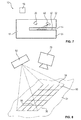
- FIG. 1 a schematic representation of an ATM 100 is shown, comprising a device 10 for reading a magnetic stripe and / or smart card, which can be fed via a slot 12 of the device 10 a card reader 16 of the device 10. Furthermore, the ATM 100 has four cash cassettes 102 and an input and / or output unit 104, over which notes of value can be paid out and / or paid in. For this purpose, the input and / or output unit 104 is connected to the cash cassettes 102 via a transport path 106.
- the device 10 for reading out data of a magnetic stripe and / or chip card can also be used in any other arbitrary device, in particular an automatic cash register system, an automatic cash deposit system and / or a payment terminal.
- the magnetic strip and / or chip card are in particular a debit card, a credit card and / or a cash card.
- a skimming module is introduced via the slot 12 into the transport path 14 of the card reader 16 of the device 10, with the aid of which the data of an imported magnetic stripe and / or chip card can be read out.
- the PIN which belongs to the magnetic card and / or smart card spied out, so that a person performing the skimming attack both the data of the magnetic stripe and / or chip card and the PIN knows and thus unauthorized withdraw money and / or can make purchases.
- skimmingabschenson designed to detect skimming modules mounted in front of the slot 12 are detected.
- Skimmingabschenson designed to detect skimming modules mounted in front of the slot 12 are detected.
- Skimmingabschenson designed to detect skimming modules mounted in front of the slot 12 are detected.
- FIGS. 2 to 10 described methods and devices used for skimming.
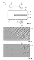
- FIG. 2 a schematic representation of a device 10 for reading a magnetic stripe and / or chip card according to a first embodiment is shown.
- the device 10 comprises, in addition to the card reader 16 with the transport path 14, a control unit 18 and an image acquisition unit embodied as a camera 20.
- images are taken with pictures of the outside 22 of the card reader 16.
- a hole pattern is provided at least in a partial region of the limiting the transport path 14 limiting element 24.
- a light source 26 is arranged, by means of which the hole pattern is transilluminated, so that, unless in the transport path 14 no object is introduced, the corresponding hole pattern are shown as bright points in the captured by the camera 20 image.
- FIG. 3 an image taken with the aid of the camera 20 is shown with the image of the area illuminated by the light source 20.
- the individual through-holes of the hole pattern are here shown as light elements, two of which are designated by the reference numerals 30, 32 by way of example.
- control unit 18 processes an image processing program with the aid of which the actual image recorded via the camera 20 compares with a preset target image of the hole pattern.
- the control unit can easily determine whether a skimming module is introduced in the transport path 14. If a skimming module is introduced, at least one of the holes of the hole pattern is concealed, so that no light from the light source 26 can pass through it and this hole is correspondingly not imaged in the image recorded with the aid of the camera 20.
- the different devices 10 are each used different hole patterns, so that the people performing the skimming attacks can not adapt the shape of their Skimmingmodule to the hole pattern and thus skimming modules can be reliably detected.
- FIG. 4 is a schematic representation of the actual image after FIG. 3 during image processing by the control unit.
- image processing in particular distances between the holes are measured so as to determine the position of the holes.
- other pattern recognition methods and / or matching methods may also be used.
- partial areas of the delimiting elements 24 may be partially transparent, so that an image of the interior of the card reader, in particular of the transport path 14, can be received via the camera 20 through these transparent areas.
- FIG. 5 Such an image taken via the camera 20 is shown, wherein the in FIG. 5 shown image shows the state when no skimming module is included in the transport path 14.
- FIG. 6 In contrast, an image taken via the camera 20 shows when a skimming module is received in the transport path 14.
- FIGS. 5 and 6 How the comparison of FIGS. 5 and 6 is an angular dark object 40 in the image in FIG. 6 recognizable, which in FIG. 5 is not provided.
- This object 40 resulted from the skimming module in that the light from the light source 24 can not illuminate at this point or not so strongly, and thus a dark area is recorded by the camera 20.
- the control unit 10 performs a segment analysis in which the images taken with the aid of the camera 20 are divided into segments and these segments are compared with predetermined segments of stored target images.
- contour determination of recorded objects can also take place and thus a comparison of contours take place.
- the determined objects can also be measured and / or their position can be determined.
- FIG. 7 a schematic representation of a device 10 for reading a magnetic stripe and / or chip card according to a second embodiment is shown.
- the camera 20 is disposed within the card reader 16, so that with their help, an image with an image of at least a portion of the transport path 14 delimiting surface 50 of the limiting element 24 can be recorded.
- a projection unit 52 is provided with the aid of which a predetermined pattern 54 is projected on the surface 50 of the delimiting element 24 at least in a partial area.
- FIG. 8 is a schematic, greatly simplified representation of this principle of operation shown.
- the pattern 54 is at the in FIG. 8 shown as a network with orthogonally intersecting network lines 56 shown. If a skimming module is introduced into the transport path 14, then the surface condition of the Surface on which the pattern 54 is projected. As a result, the position of the crossing points 58 at which the network lines 56 intersect changes. By comparing the positions of the individual intersections and the desired positions according to the predetermined target image determined in the image recorded via the camera 20, it is easy to detect when a skimming module is inserted.
- any other arbitrary pattern can be projected, which makes it possible to detect an object in the region of the pattern 54 by determining changes in the pattern in the images determined by the camera 20.
- FIG. 9 an illustration of a device 10 of a magnetic stripe and / or chip card according to a third embodiment is shown.
- the camera 20 is not arranged inside the card reader 16, but is located outside of the card reader 16.
- an optical deflection element 60 for example a deflection prism, is provided with the aid of which the detection range of the camera 20 indicated via the line 62 is deflected in such a way, an image with an image of the projected pattern 54 can be recorded with the aid of the camera 20.
- FIG. 10 a schematic representation of a device 10 for reading a magnetic stripe and / or chip card is shown with a fourth embodiment.
- a light source 70 is provided, with the aid of which a pulsed light is emitted to at least a portion 72 of the transport path.
- the aid of the camera 20 With the aid of the camera 20, at least one image is recorded with an image of this subregion 72, wherein the image recordings via the camera 20 are synchronized with the pulsed light of the light source 70.
- distances within the subarea 72 in the images taken via the camera 20 can be determined in a simple manner, so that the presence of a skimming module in the transport path 14 can be detected in a simple manner via deviations between determined distances and predetermined, planned distances ,
- the individual embodiments described above can also be combined. By simultaneously applying several of these embodiments, the safety for the detection of skimming modules can be further increased.
- various different embodiments of the previously described embodiment can be used in different subregions of the transport path parallel to each other.
Priority Applications (7)
| Application Number | Priority Date | Filing Date | Title |
|---|---|---|---|
| EP12194205.6A EP2736026B1 (fr) | 2012-11-26 | 2012-11-26 | Dispositif de lecture de cartes à puce et/ou à bandes magnétiques avec une caméra pour la détection de modules de skimming intégrés |
| US14/647,301 US9754462B2 (en) | 2012-11-26 | 2013-11-26 | Device for reading a magnetic stripe and/or chip card having a camera for the detection of inserted skimming modules |
| EA201591034A EA201591034A1 (ru) | 2012-11-26 | 2013-11-26 | Устройство для считывания карты с магнитной полосой и/или чип-карты, содержащее камеру для обнаружения вдвинутых скимминговых модулей |
| CN201380060551.0A CN104798117B (zh) | 2012-11-26 | 2013-11-26 | 具有用于检测置入测录模块的摄像头的磁条卡和/或芯片卡读取设备 |
| BR112015009626-3A BR112015009626B1 (pt) | 2012-11-26 | 2013-11-26 | Dispositivo para leitura de um cartão de tarja magnética e/ou de chip com um leitor de cartão |
| PCT/EP2013/074706 WO2014080031A1 (fr) | 2012-11-26 | 2013-11-26 | Dispositif de lecture d'une carte à piste magnétique et/ou à puce comprenant une caméra de détection de modules de skimming insérés |
| US15/695,695 US10748387B2 (en) | 2012-11-26 | 2017-09-05 | Device for reading a magnetic stripe and/or chip card having a camera for the detection of inserted skimming modules |
Applications Claiming Priority (1)
| Application Number | Priority Date | Filing Date | Title |
|---|---|---|---|
| EP12194205.6A EP2736026B1 (fr) | 2012-11-26 | 2012-11-26 | Dispositif de lecture de cartes à puce et/ou à bandes magnétiques avec une caméra pour la détection de modules de skimming intégrés |
Publications (2)
| Publication Number | Publication Date |
|---|---|
| EP2736026A1 true EP2736026A1 (fr) | 2014-05-28 |
| EP2736026B1 EP2736026B1 (fr) | 2020-03-25 |
Family
ID=47471500
Family Applications (1)
| Application Number | Title | Priority Date | Filing Date |
|---|---|---|---|
| EP12194205.6A Active EP2736026B1 (fr) | 2012-11-26 | 2012-11-26 | Dispositif de lecture de cartes à puce et/ou à bandes magnétiques avec une caméra pour la détection de modules de skimming intégrés |
Country Status (6)
| Country | Link |
|---|---|
| US (2) | US9754462B2 (fr) |
| EP (1) | EP2736026B1 (fr) |
| CN (1) | CN104798117B (fr) |
| BR (1) | BR112015009626B1 (fr) |
| EA (1) | EA201591034A1 (fr) |
| WO (1) | WO2014080031A1 (fr) |
Cited By (1)
| Publication number | Priority date | Publication date | Assignee | Title |
|---|---|---|---|---|
| US11610457B2 (en) | 2020-11-03 | 2023-03-21 | Bank Of America Corporation | Detecting unauthorized activity related to a computer peripheral device by monitoring voltage of the peripheral device |
Families Citing this family (11)
| Publication number | Priority date | Publication date | Assignee | Title |
|---|---|---|---|---|
| US9818049B2 (en) * | 2011-12-08 | 2017-11-14 | Tmd Holding B.V. | Anti skimming and anti shimming card feed unit, kernel element, read out unit, transaction machine and method |
| EP3100227B1 (fr) * | 2014-01-28 | 2020-01-08 | Capital One Financial Corporation | Détection de dispositifs non autorisés sur des gab |
| US10262326B1 (en) | 2017-07-31 | 2019-04-16 | Wells Fargo Bank, N.A. | Anti-skimming card reader computing device |
| CN108898756A (zh) * | 2018-05-04 | 2018-11-27 | 深圳怡化电脑股份有限公司 | 一种业务的安全处理方法、系统及金融终端 |
| US10599964B1 (en) | 2019-01-15 | 2020-03-24 | Capital One Services, Llc | System and method for transmitting financial information via color matrix code |
| US10628638B1 (en) * | 2019-03-22 | 2020-04-21 | Capital One Services, Llc | Techniques to automatically detect fraud devices |
| CN111581144B (zh) * | 2020-03-24 | 2022-02-08 | 惠州市德赛西威智能交通技术研究院有限公司 | 一种车载摄像头热插入自恢复方法、装置及存储介质 |
| US20220114351A1 (en) * | 2020-10-14 | 2022-04-14 | Ncr Corporation | System and method for detecting a smart card |
| US11875652B2 (en) | 2021-10-22 | 2024-01-16 | Kyndryl, Inc. | Card skimming detection |
| JP2024025145A (ja) * | 2022-08-10 | 2024-02-26 | ニデックインスツルメンツ株式会社 | 異物検知装置、カードリーダ、異物検知方法、及び異物検知プログラム |
| US11790189B1 (en) * | 2022-08-31 | 2023-10-17 | Ncr Corporation | System and method for detecting a foreign object |
Citations (9)
| Publication number | Priority date | Publication date | Assignee | Title |
|---|---|---|---|---|
| JPS60220808A (ja) * | 1984-04-17 | 1985-11-05 | Inax Corp | 表面検査方法 |
| JPH08313222A (ja) * | 1995-05-24 | 1996-11-29 | Matsushita Electric Ind Co Ltd | 透明物体の検査方法 |
| US20090201372A1 (en) * | 2006-02-13 | 2009-08-13 | Fraudhalt, Ltd. | Method and apparatus for integrated atm surveillance |
| DE102009018319A1 (de) * | 2009-04-22 | 2010-10-28 | Wincor Nixdorf International Gmbh | Selbstbedienungsterminal mit mindestens einer Kamera zum Erkennen von Manipulationsversuchen |
| DE102009018320A1 (de) | 2009-04-22 | 2010-10-28 | Wincor Nixdorf International Gmbh | Verfahren zum Erkennen von Manipulationsversuchen an einem Selbstbedienungsterminal und Datenverarbeitungseinheit dafür |
| DE102009018322A1 (de) | 2009-04-22 | 2010-10-28 | Wincor Nixdorf International Gmbh | Selbstbedienungsterminal mit Kamera zum Erkennen von Manipulationsversuchen |
| DE102010036961A1 (de) | 2010-08-12 | 2012-02-16 | Wincor Nixdorf International Gmbh | Verfahren und Vorrichtung zum Erkennen und Verifizieren von Manipulationsversuchen an einem Selbstbedienungsterminal |
| DE102011010737A1 (de) | 2011-02-09 | 2012-08-09 | Stephan Maaß | Verfahren zur Verbesserung des Manipulationsschutzes von Geldautomaten, sowie Geldautomat zur Durchführung des Verfahrens |
| DE102011001541A1 (de) | 2011-03-24 | 2012-09-27 | Wincor Nixdorf International Gmbh | Selbstbedienungs-Terminal und Verfahren zur Überwachung eines Benutzer-Aufenthaltsbereichs |
Family Cites Families (19)
| Publication number | Priority date | Publication date | Assignee | Title |
|---|---|---|---|---|
| US8640947B1 (en) * | 2002-11-26 | 2014-02-04 | Diebold Self-Service Systems, Division Of Diebold, Incorporated | Automated banking machine operated responsive to data bearing records with improved resistance to fraud |
| WO2005109315A2 (fr) * | 2004-04-30 | 2005-11-17 | Utc Fire & Safety Corp. | Systeme securise d'atm |
| US7458516B2 (en) * | 2005-11-14 | 2008-12-02 | Ncr Corporation | Card reader |
| WO2007062155A2 (fr) * | 2005-11-21 | 2007-05-31 | American Bank Note Holographics, Inc. | Bande magnetique a motif holographique masque et procede de formation et lecteur correspondants |
| US20070200928A1 (en) * | 2006-02-13 | 2007-08-30 | O'doherty Phelim A | Method and apparatus for automated video surveillance |
| KR100863744B1 (ko) * | 2006-06-15 | 2008-10-16 | 노틸러스효성 주식회사 | 고객정보 유출 방지 핀패드 및 이를 부착한 금융자동화기기 |
| JP2008027259A (ja) * | 2006-07-24 | 2008-02-07 | Hitachi Omron Terminal Solutions Corp | 不審物又は形状変化検知システム |
| US7354003B1 (en) * | 2006-09-15 | 2008-04-08 | Ncr Corporation | Card reader |
| CN101276499B (zh) * | 2008-04-18 | 2010-09-01 | 浙江工业大学 | 基于全方位计算机视觉的atm设备的智能监控装置 |
| US9147324B2 (en) * | 2009-02-23 | 2015-09-29 | Honeywell International Inc. | System and method to detect tampering at ATM machines |
| DE102009018318A1 (de) * | 2009-04-22 | 2010-10-28 | Wincor Nixdorf International Gmbh | Selbstbedienungsterminal mit mindestens einer Bilddaten erzeugenden Kamera zum Erkennen von Manipulationsversuchen |
| US8736199B2 (en) * | 2010-04-13 | 2014-05-27 | John M. J. Madey | Temperature stabilized microwave electron gun |
| CN201965699U (zh) * | 2011-01-14 | 2011-09-07 | 由田新技股份有限公司 | Atm监控装置 |
| US8633969B2 (en) * | 2011-02-09 | 2014-01-21 | Omnivision Technologies, Inc. | Apparatus and method for three-dimensional image capture with extended depth of field |
| DE102011011541A1 (de) | 2011-02-17 | 2012-08-23 | Fraunhofer-Gesellschaft zur Förderung der angewandten Forschung e.V. | Ultraschallwandleranordnung mit einem Ultraschallwellen fokussierenden Mittel sowie Verfahren zum fokussierten Abstrahlen sowie Empfangen von fokussierten Ultraschallwellen |
| GB2488538B (en) * | 2011-02-22 | 2017-02-22 | Atm Parts Company Ltd | Apparatus and method for monitoring a card slot |
| US8523072B2 (en) * | 2011-12-13 | 2013-09-03 | Parabit Systems, Inc. | Card reader protection system |
| US9767422B2 (en) * | 2013-03-12 | 2017-09-19 | Diebold Self-Service Systems, Division Of Diebold, Incorporated | Detecting unauthorized card skimmers |
| KR101797118B1 (ko) * | 2016-05-09 | 2017-11-14 | 한국과학기술연구원 | 단일 펄스 레이저 장치 |
-
2012
- 2012-11-26 EP EP12194205.6A patent/EP2736026B1/fr active Active
-
2013
- 2013-11-26 EA EA201591034A patent/EA201591034A1/ru unknown
- 2013-11-26 US US14/647,301 patent/US9754462B2/en active Active
- 2013-11-26 CN CN201380060551.0A patent/CN104798117B/zh active Active
- 2013-11-26 BR BR112015009626-3A patent/BR112015009626B1/pt active IP Right Grant
- 2013-11-26 WO PCT/EP2013/074706 patent/WO2014080031A1/fr active Application Filing
-
2017
- 2017-09-05 US US15/695,695 patent/US10748387B2/en active Active
Patent Citations (9)
| Publication number | Priority date | Publication date | Assignee | Title |
|---|---|---|---|---|
| JPS60220808A (ja) * | 1984-04-17 | 1985-11-05 | Inax Corp | 表面検査方法 |
| JPH08313222A (ja) * | 1995-05-24 | 1996-11-29 | Matsushita Electric Ind Co Ltd | 透明物体の検査方法 |
| US20090201372A1 (en) * | 2006-02-13 | 2009-08-13 | Fraudhalt, Ltd. | Method and apparatus for integrated atm surveillance |
| DE102009018319A1 (de) * | 2009-04-22 | 2010-10-28 | Wincor Nixdorf International Gmbh | Selbstbedienungsterminal mit mindestens einer Kamera zum Erkennen von Manipulationsversuchen |
| DE102009018320A1 (de) | 2009-04-22 | 2010-10-28 | Wincor Nixdorf International Gmbh | Verfahren zum Erkennen von Manipulationsversuchen an einem Selbstbedienungsterminal und Datenverarbeitungseinheit dafür |
| DE102009018322A1 (de) | 2009-04-22 | 2010-10-28 | Wincor Nixdorf International Gmbh | Selbstbedienungsterminal mit Kamera zum Erkennen von Manipulationsversuchen |
| DE102010036961A1 (de) | 2010-08-12 | 2012-02-16 | Wincor Nixdorf International Gmbh | Verfahren und Vorrichtung zum Erkennen und Verifizieren von Manipulationsversuchen an einem Selbstbedienungsterminal |
| DE102011010737A1 (de) | 2011-02-09 | 2012-08-09 | Stephan Maaß | Verfahren zur Verbesserung des Manipulationsschutzes von Geldautomaten, sowie Geldautomat zur Durchführung des Verfahrens |
| DE102011001541A1 (de) | 2011-03-24 | 2012-09-27 | Wincor Nixdorf International Gmbh | Selbstbedienungs-Terminal und Verfahren zur Überwachung eines Benutzer-Aufenthaltsbereichs |
Cited By (1)
| Publication number | Priority date | Publication date | Assignee | Title |
|---|---|---|---|---|
| US11610457B2 (en) | 2020-11-03 | 2023-03-21 | Bank Of America Corporation | Detecting unauthorized activity related to a computer peripheral device by monitoring voltage of the peripheral device |
Also Published As
| Publication number | Publication date |
|---|---|
| BR112015009626A2 (pt) | 2017-07-04 |
| BR112015009626B1 (pt) | 2021-11-16 |
| CN104798117A (zh) | 2015-07-22 |
| EP2736026B1 (fr) | 2020-03-25 |
| WO2014080031A1 (fr) | 2014-05-30 |
| US20180040206A1 (en) | 2018-02-08 |
| EA201591034A1 (ru) | 2015-09-30 |
| US20150302707A1 (en) | 2015-10-22 |
| CN104798117B (zh) | 2017-08-29 |
| US9754462B2 (en) | 2017-09-05 |
| US10748387B2 (en) | 2020-08-18 |
Similar Documents
| Publication | Publication Date | Title |
|---|---|---|
| EP2736026B1 (fr) | Dispositif de lecture de cartes à puce et/ou à bandes magnétiques avec une caméra pour la détection de modules de skimming intégrés | |
| EP1307855B1 (fr) | Dispositif de lecture de cartes d'autorisation a code barres | |
| DE60309299T2 (de) | System und Verfahren zur Ablaufverfolgung von Banknoten | |
| EP2897112B1 (fr) | Procédé et dispositif de prévention des fausses alertes dans les systèmes de surveillance | |
| AT4894U1 (de) | Einrichtung zum schutz von sb-automaten gegen manipulationen | |
| EP2656328A1 (fr) | Procédé et dispositif de détermination d'un ensemble de données de référence de classe, pour la classification de documents de valeur | |
| EP2797057B1 (fr) | Dispositif de lecture de cartes à bande magnétique et/ou à puce et procédé permettant d'éviter les tentatives de clonage | |
| EP2722788B1 (fr) | Dispositif de lecture d'une carte à puce et procédé de détection d'un module de skimming | |
| WO2010043358A1 (fr) | Procédé et dispositif de traitement de documents de valeur | |
| EP3357043B1 (fr) | Document et procédé pour verifier l'autenticité d'un document | |
| DE102005052671A1 (de) | Verfahren und System zum Überprüfen von geldwerten Dokumenten | |
| DE10132589B4 (de) | Verfahren zur qualitativen Beurteilung von Material | |
| EP0337921A2 (fr) | Système pour reconnaître et sécuriser des objets ainsi que son application | |
| EP2897108B1 (fr) | Unité de contrôle pour la détection de modules de skimming | |
| EP3142039B1 (fr) | Terminal self-service équipé avec dispositif de lecture de carte ainsi que procédé de surveillance | |
| DE102015115172A1 (de) | Verfahren und Vorrichtung zur Bestimmung der Integrität einer Kartenleseeinrichtung und ein damit ausgestattetes Selbstbedienungsterminal | |
| DE202005018964U1 (de) | Vorrichtung zum Prüfen der Echtheit von Dokumenten | |
| DE102005009332A1 (de) | Verfahren und Vorrichtung für die Überprüfung der Vereinzelung von Banknoten | |
| EP2920769B1 (fr) | L'appareil et methode pour evaluer les documents de valeur | |
| EP3563356B1 (fr) | Procédé et dispositif permettant de détecter un fil de sécurité dans un document de valeur | |
| DE202011105565U1 (de) | Prüfkarte | |
| EP3563357B1 (fr) | Procédé et dispositif permettant de détecter un fil de sécurité dans un document de valeur | |
| DE102022124736B3 (de) | Gateanordnung, insbesondere für ein Personentransportsystem | |
| EP2338130B1 (fr) | Procédé pour la reconnaissance optique automatique de caractères, produit-programme informatique, système informatique et numériseur | |
| DE102004026557A1 (de) | Authentifizierungsverfahren und Authentifizierungssystem |
Legal Events
| Date | Code | Title | Description |
|---|---|---|---|
| PUAI | Public reference made under article 153(3) epc to a published international application that has entered the european phase |
Free format text: ORIGINAL CODE: 0009012 |
|
| 17P | Request for examination filed |
Effective date: 20121126 |
|
| AK | Designated contracting states |
Kind code of ref document: A1 Designated state(s): AL AT BE BG CH CY CZ DE DK EE ES FI FR GB GR HR HU IE IS IT LI LT LU LV MC MK MT NL NO PL PT RO RS SE SI SK SM TR |
|
| AX | Request for extension of the european patent |
Extension state: BA ME |
|
| R17P | Request for examination filed (corrected) |
Effective date: 20141113 |
|
| RBV | Designated contracting states (corrected) |
Designated state(s): AL AT BE BG CH CY CZ DE DK EE ES FI FR GB GR HR HU IE IS IT LI LT LU LV MC MK MT NL NO PL PT RO RS SE SI SK SM TR |
|
| STAA | Information on the status of an ep patent application or granted ep patent |
Free format text: STATUS: EXAMINATION IS IN PROGRESS |
|
| 17Q | First examination report despatched |
Effective date: 20181029 |
|
| RIN1 | Information on inventor provided before grant (corrected) |
Inventor name: DRICHEL, ALEXANDER Inventor name: SCHLIEBE, DIETER Inventor name: WIESINGER, TORSTEN Inventor name: PRIESTERJAHN, STEFFEN |
|
| GRAP | Despatch of communication of intention to grant a patent |
Free format text: ORIGINAL CODE: EPIDOSNIGR1 |
|
| STAA | Information on the status of an ep patent application or granted ep patent |
Free format text: STATUS: GRANT OF PATENT IS INTENDED |
|
| INTG | Intention to grant announced |
Effective date: 20191023 |
|
| GRAS | Grant fee paid |
Free format text: ORIGINAL CODE: EPIDOSNIGR3 |
|
| GRAA | (expected) grant |
Free format text: ORIGINAL CODE: 0009210 |
|
| STAA | Information on the status of an ep patent application or granted ep patent |
Free format text: STATUS: THE PATENT HAS BEEN GRANTED |
|
| AK | Designated contracting states |
Kind code of ref document: B1 Designated state(s): AL AT BE BG CH CY CZ DE DK EE ES FI FR GB GR HR HU IE IS IT LI LT LU LV MC MK MT NL NO PL PT RO RS SE SI SK SM TR |
|
| REG | Reference to a national code |
Ref country code: GB Ref legal event code: FG4D Free format text: NOT ENGLISH |
|
| RIN1 | Information on inventor provided before grant (corrected) |
Inventor name: SCHLIEBE, DIETER Inventor name: DRICHEL, ALEXANDER Inventor name: WIESINGER, TORSTEN Inventor name: PRIESTERJAHN, STEFFEN |
|
| REG | Reference to a national code |
Ref country code: DE Ref legal event code: R096 Ref document number: 502012015892 Country of ref document: DE |
|
| REG | Reference to a national code |
Ref country code: AT Ref legal event code: REF Ref document number: 1249459 Country of ref document: AT Kind code of ref document: T Effective date: 20200415 Ref country code: IE Ref legal event code: FG4D Free format text: LANGUAGE OF EP DOCUMENT: GERMAN |
|
| PG25 | Lapsed in a contracting state [announced via postgrant information from national office to epo] |
Ref country code: RS Free format text: LAPSE BECAUSE OF FAILURE TO SUBMIT A TRANSLATION OF THE DESCRIPTION OR TO PAY THE FEE WITHIN THE PRESCRIBED TIME-LIMIT Effective date: 20200325 Ref country code: FI Free format text: LAPSE BECAUSE OF FAILURE TO SUBMIT A TRANSLATION OF THE DESCRIPTION OR TO PAY THE FEE WITHIN THE PRESCRIBED TIME-LIMIT Effective date: 20200325 Ref country code: NO Free format text: LAPSE BECAUSE OF FAILURE TO SUBMIT A TRANSLATION OF THE DESCRIPTION OR TO PAY THE FEE WITHIN THE PRESCRIBED TIME-LIMIT Effective date: 20200625 |
|
| PG25 | Lapsed in a contracting state [announced via postgrant information from national office to epo] |
Ref country code: HR Free format text: LAPSE BECAUSE OF FAILURE TO SUBMIT A TRANSLATION OF THE DESCRIPTION OR TO PAY THE FEE WITHIN THE PRESCRIBED TIME-LIMIT Effective date: 20200325 Ref country code: SE Free format text: LAPSE BECAUSE OF FAILURE TO SUBMIT A TRANSLATION OF THE DESCRIPTION OR TO PAY THE FEE WITHIN THE PRESCRIBED TIME-LIMIT Effective date: 20200325 Ref country code: LV Free format text: LAPSE BECAUSE OF FAILURE TO SUBMIT A TRANSLATION OF THE DESCRIPTION OR TO PAY THE FEE WITHIN THE PRESCRIBED TIME-LIMIT Effective date: 20200325 Ref country code: GR Free format text: LAPSE BECAUSE OF FAILURE TO SUBMIT A TRANSLATION OF THE DESCRIPTION OR TO PAY THE FEE WITHIN THE PRESCRIBED TIME-LIMIT Effective date: 20200626 Ref country code: BG Free format text: LAPSE BECAUSE OF FAILURE TO SUBMIT A TRANSLATION OF THE DESCRIPTION OR TO PAY THE FEE WITHIN THE PRESCRIBED TIME-LIMIT Effective date: 20200625 |
|
| REG | Reference to a national code |
Ref country code: NL Ref legal event code: MP Effective date: 20200325 |
|
| REG | Reference to a national code |
Ref country code: LT Ref legal event code: MG4D |
|
| PG25 | Lapsed in a contracting state [announced via postgrant information from national office to epo] |
Ref country code: NL Free format text: LAPSE BECAUSE OF FAILURE TO SUBMIT A TRANSLATION OF THE DESCRIPTION OR TO PAY THE FEE WITHIN THE PRESCRIBED TIME-LIMIT Effective date: 20200325 |
|
| PG25 | Lapsed in a contracting state [announced via postgrant information from national office to epo] |
Ref country code: IS Free format text: LAPSE BECAUSE OF FAILURE TO SUBMIT A TRANSLATION OF THE DESCRIPTION OR TO PAY THE FEE WITHIN THE PRESCRIBED TIME-LIMIT Effective date: 20200725 Ref country code: RO Free format text: LAPSE BECAUSE OF FAILURE TO SUBMIT A TRANSLATION OF THE DESCRIPTION OR TO PAY THE FEE WITHIN THE PRESCRIBED TIME-LIMIT Effective date: 20200325 Ref country code: CZ Free format text: LAPSE BECAUSE OF FAILURE TO SUBMIT A TRANSLATION OF THE DESCRIPTION OR TO PAY THE FEE WITHIN THE PRESCRIBED TIME-LIMIT Effective date: 20200325 Ref country code: SK Free format text: LAPSE BECAUSE OF FAILURE TO SUBMIT A TRANSLATION OF THE DESCRIPTION OR TO PAY THE FEE WITHIN THE PRESCRIBED TIME-LIMIT Effective date: 20200325 Ref country code: LT Free format text: LAPSE BECAUSE OF FAILURE TO SUBMIT A TRANSLATION OF THE DESCRIPTION OR TO PAY THE FEE WITHIN THE PRESCRIBED TIME-LIMIT Effective date: 20200325 Ref country code: PT Free format text: LAPSE BECAUSE OF FAILURE TO SUBMIT A TRANSLATION OF THE DESCRIPTION OR TO PAY THE FEE WITHIN THE PRESCRIBED TIME-LIMIT Effective date: 20200818 Ref country code: EE Free format text: LAPSE BECAUSE OF FAILURE TO SUBMIT A TRANSLATION OF THE DESCRIPTION OR TO PAY THE FEE WITHIN THE PRESCRIBED TIME-LIMIT Effective date: 20200325 Ref country code: SM Free format text: LAPSE BECAUSE OF FAILURE TO SUBMIT A TRANSLATION OF THE DESCRIPTION OR TO PAY THE FEE WITHIN THE PRESCRIBED TIME-LIMIT Effective date: 20200325 |
|
| REG | Reference to a national code |
Ref country code: DE Ref legal event code: R097 Ref document number: 502012015892 Country of ref document: DE |
|
| PG25 | Lapsed in a contracting state [announced via postgrant information from national office to epo] |
Ref country code: DK Free format text: LAPSE BECAUSE OF FAILURE TO SUBMIT A TRANSLATION OF THE DESCRIPTION OR TO PAY THE FEE WITHIN THE PRESCRIBED TIME-LIMIT Effective date: 20200325 Ref country code: ES Free format text: LAPSE BECAUSE OF FAILURE TO SUBMIT A TRANSLATION OF THE DESCRIPTION OR TO PAY THE FEE WITHIN THE PRESCRIBED TIME-LIMIT Effective date: 20200325 Ref country code: IT Free format text: LAPSE BECAUSE OF FAILURE TO SUBMIT A TRANSLATION OF THE DESCRIPTION OR TO PAY THE FEE WITHIN THE PRESCRIBED TIME-LIMIT Effective date: 20200325 |
|
| PLBE | No opposition filed within time limit |
Free format text: ORIGINAL CODE: 0009261 |
|
| STAA | Information on the status of an ep patent application or granted ep patent |
Free format text: STATUS: NO OPPOSITION FILED WITHIN TIME LIMIT |
|
| PG25 | Lapsed in a contracting state [announced via postgrant information from national office to epo] |
Ref country code: PL Free format text: LAPSE BECAUSE OF FAILURE TO SUBMIT A TRANSLATION OF THE DESCRIPTION OR TO PAY THE FEE WITHIN THE PRESCRIBED TIME-LIMIT Effective date: 20200325 |
|
| 26N | No opposition filed |
Effective date: 20210112 |
|
| PG25 | Lapsed in a contracting state [announced via postgrant information from national office to epo] |
Ref country code: SI Free format text: LAPSE BECAUSE OF FAILURE TO SUBMIT A TRANSLATION OF THE DESCRIPTION OR TO PAY THE FEE WITHIN THE PRESCRIBED TIME-LIMIT Effective date: 20200325 |
|
| PG25 | Lapsed in a contracting state [announced via postgrant information from national office to epo] |
Ref country code: MC Free format text: LAPSE BECAUSE OF FAILURE TO SUBMIT A TRANSLATION OF THE DESCRIPTION OR TO PAY THE FEE WITHIN THE PRESCRIBED TIME-LIMIT Effective date: 20200325 |
|
| REG | Reference to a national code |
Ref country code: CH Ref legal event code: PL |
|
| PG25 | Lapsed in a contracting state [announced via postgrant information from national office to epo] |
Ref country code: LU Free format text: LAPSE BECAUSE OF NON-PAYMENT OF DUE FEES Effective date: 20201126 |
|
| REG | Reference to a national code |
Ref country code: BE Ref legal event code: MM Effective date: 20201130 |
|
| PG25 | Lapsed in a contracting state [announced via postgrant information from national office to epo] |
Ref country code: LI Free format text: LAPSE BECAUSE OF NON-PAYMENT OF DUE FEES Effective date: 20201130 Ref country code: CH Free format text: LAPSE BECAUSE OF NON-PAYMENT OF DUE FEES Effective date: 20201130 |
|
| PG25 | Lapsed in a contracting state [announced via postgrant information from national office to epo] |
Ref country code: IE Free format text: LAPSE BECAUSE OF NON-PAYMENT OF DUE FEES Effective date: 20201126 |
|
| REG | Reference to a national code |
Ref country code: AT Ref legal event code: MM01 Ref document number: 1249459 Country of ref document: AT Kind code of ref document: T Effective date: 20201126 |
|
| PG25 | Lapsed in a contracting state [announced via postgrant information from national office to epo] |
Ref country code: AT Free format text: LAPSE BECAUSE OF NON-PAYMENT OF DUE FEES Effective date: 20201126 |
|
| PG25 | Lapsed in a contracting state [announced via postgrant information from national office to epo] |
Ref country code: TR Free format text: LAPSE BECAUSE OF FAILURE TO SUBMIT A TRANSLATION OF THE DESCRIPTION OR TO PAY THE FEE WITHIN THE PRESCRIBED TIME-LIMIT Effective date: 20200325 Ref country code: MT Free format text: LAPSE BECAUSE OF FAILURE TO SUBMIT A TRANSLATION OF THE DESCRIPTION OR TO PAY THE FEE WITHIN THE PRESCRIBED TIME-LIMIT Effective date: 20200325 Ref country code: CY Free format text: LAPSE BECAUSE OF FAILURE TO SUBMIT A TRANSLATION OF THE DESCRIPTION OR TO PAY THE FEE WITHIN THE PRESCRIBED TIME-LIMIT Effective date: 20200325 |
|
| PG25 | Lapsed in a contracting state [announced via postgrant information from national office to epo] |
Ref country code: MK Free format text: LAPSE BECAUSE OF FAILURE TO SUBMIT A TRANSLATION OF THE DESCRIPTION OR TO PAY THE FEE WITHIN THE PRESCRIBED TIME-LIMIT Effective date: 20200325 Ref country code: AL Free format text: LAPSE BECAUSE OF FAILURE TO SUBMIT A TRANSLATION OF THE DESCRIPTION OR TO PAY THE FEE WITHIN THE PRESCRIBED TIME-LIMIT Effective date: 20200325 |
|
| PG25 | Lapsed in a contracting state [announced via postgrant information from national office to epo] |
Ref country code: BE Free format text: LAPSE BECAUSE OF NON-PAYMENT OF DUE FEES Effective date: 20201130 |
|
| REG | Reference to a national code |
Ref country code: FR Ref legal event code: PLFP Year of fee payment: 11 |
|
| REG | Reference to a national code |
Ref country code: GB Ref legal event code: 732E Free format text: REGISTERED BETWEEN 20230323 AND 20230329 |
|
| REG | Reference to a national code |
Ref country code: GB Ref legal event code: 732E Free format text: REGISTERED BETWEEN 20230525 AND 20230601 |
|
| REG | Reference to a national code |
Ref country code: DE Ref legal event code: R081 Ref document number: 502012015892 Country of ref document: DE Owner name: DIEBOLD NIXDORF SYSTEMS GMBH, DE Free format text: FORMER OWNER: WINCOR NIXDORF INTERNATIONAL GMBH, 33106 PADERBORN, DE |
|
| PGFP | Annual fee paid to national office [announced via postgrant information from national office to epo] |
Ref country code: GB Payment date: 20231019 Year of fee payment: 12 |
|
| PGFP | Annual fee paid to national office [announced via postgrant information from national office to epo] |
Ref country code: FR Payment date: 20231019 Year of fee payment: 12 Ref country code: DE Payment date: 20231019 Year of fee payment: 12 |